1. Introduction
Electric motors with inserted permanent magnets (PMs) offer high-torque-density structures, especially for electric vehicle (EV) applications requiring low-volume motors [
1]. Different PM configurations are applied, leading to two main categories: (1) rotor–PM and (2) stator–PM motors. Rotor–PM motors are increasingly used in various industries and are primarily categorised into interior-PM (IPM) and surface-PM (SPM) motors [
2,
3]. Over the last twenty-five years, thanks to some superiorities of the stator–PM motors compared to rotor–PM motors, there has been an increase in focus on stator–PM motors. These superiorities over the rotor–PM motors include elimination of the centrifugal forces and vibrations on the PMs, which exist in the rotating parts, easier PM heat management, and a robust rotor structure [
4,
5].
Additionally, the stator–PM motors can manoeuvre in low-speed applications with high-efficiency performance thanks to the magnet gearing effect [
6,
7]. Therefore, stator–PM motors benefit from direct-drive capability and reduced losses associated with the gearbox [
8]. The aforementioned merits of stator–PM motors have led to the insertion of PMs into the stator area of Switched Reluctance Motors (SRMs). PM-assisted SRMs (PMaSRMs) significantly improve torque density compared to conventional SRMs, even though they still suffer from the low torque density and high torque ripple inherent to the original SRM structure [
9]. Drawing inspiration from the PMaSRM structure and applying three-phase sinusoidal excitation, the doubly salient PM motors (DSPMs) further enhance torque density [
10]. This improvement comes from doubling the energy conversion quadrants, whereas SRMs operate with only one quadrant of energy conversion. The original DSPMs are still from high torque ripple. The PMs are arranged in conventional DSPMs such that, after every two stator poles, one PM is placed in the stator yoke [
11,
12]. This results in a smaller number of PMs positioned across the entire stator space, with each PM having an opposite magnetisation direction to its adjacent PMs.
Due to varying PM configurations, the no-load and full-load characteristics of stator–PM motors can change significantly. Thus, based on the PM arrangement, in addition to DSPMs, other categories of stator–PM motors are obtained, including flux-switching PM (FSPM) and flux-reversal PM (FRPM) motors. Furthermore, another enhanced DSPM structure, known as a biased-flux PM (BFPM) motor, exhibits effects similar to those of DSPMs and improves torque performance, although it typically increases PM volume compared to conventional DSPMs [
5,
13]. In BFPMs, PMs are tangentially magnetised and positioned between two stator poles, resulting in benefits from the flux-concentrating effect [
14]. Overall, stator–PM motors can be generally classified into four main categories: DSPM, BFPM, FSPM, and FRPM topologies.
FSPMs constitute a major category of stator–PM motors and achieve high torque density owing to their four-quadrant energy conversion [
15]. Conventional FSPMs consist of C-core modules, with PMs positioned between every two C-core modules and magnetised in opposite directions to their adjacent PMs [
16]. This PM arrangement leads to the inherent flux concentration effect of FSPMs and increases torque production [
17]. In FSPM structures, the PMs are positioned between the armature windings, which can increase the risk of demagnetisation as the PMs are located in the primary heat source area. Although the torque density of conventional FSPMs is significantly higher than that of other categories of stator–PM motors, it also requires a larger PM volume. Thus, both the high PM volume and the increased demagnetisation risk indicate that the FSPM structure still requires improvement [
18]. Generally, to prevent the risk of PM demagnetisation in FSPM motors, more precise control over factors such as current density, load, and copper losses is required. Additionally, to reduce PM volume in FSPM structures, an E-type core (E-core) can be utilised, which adds an auxiliary tooth between two adjacent armature coils, increasing the torque by up to 15% [
19]. In addition, the auxiliary teeth in the E-type motor increase the fault tolerance capability [
20].
Similar to the operating principles of FSPMs, FRPMs leverage four-quadrant energy conversion and high-torque-density structures [
21]. The PM array in conventional FRPMs covers the stator surface, leading to a high PM volume in these machines and an increased effective air gap [
21,
22,
23,
24]. Although PMs in FRPMs benefit from improved thermal management, they still face a significant demagnetisation risk because the PM flux is in series with the armature flux [
25]. One of the improved FRPM structures utilises a consequent pole (CP) arrangement [
26,
27]. In CPFRPM structures, approximately half of the PMs are replaced with an iron core [
28]. This substitution leads to notable improvements, including a notable reduction in PM volume despite an increase in torque density, as well as the creation of a new path for the armature flux alongside the PMs [
24]. This results in parallel alignment of these two flux types, thereby reducing PM demagnetisation risks in FRPMs [
29,
30,
31].
This paper proposes an innovative design procedure for stator–PM motors to reduce PM volume while improving the motor performance. The methodology of the design process is described in detail in
Section 2, where the step-by-step procedure is outlined, and the transition from the conventional E-type structure to the new topologies is explained. The analytical reasons behind the architecture of the novel motors are expressed in
Section 3, and finite element analysis (FEA) verifications are also conducted.
Section 4 thoroughly investigates the obtained motors’ genetic algorithm optimisation procedure. Based on the optimisation results, the selected motors are comprehensively examined for their electromagnetic operations in
Section 5. Finally, a conclusion is provided in
Section 6.
2. Methodology
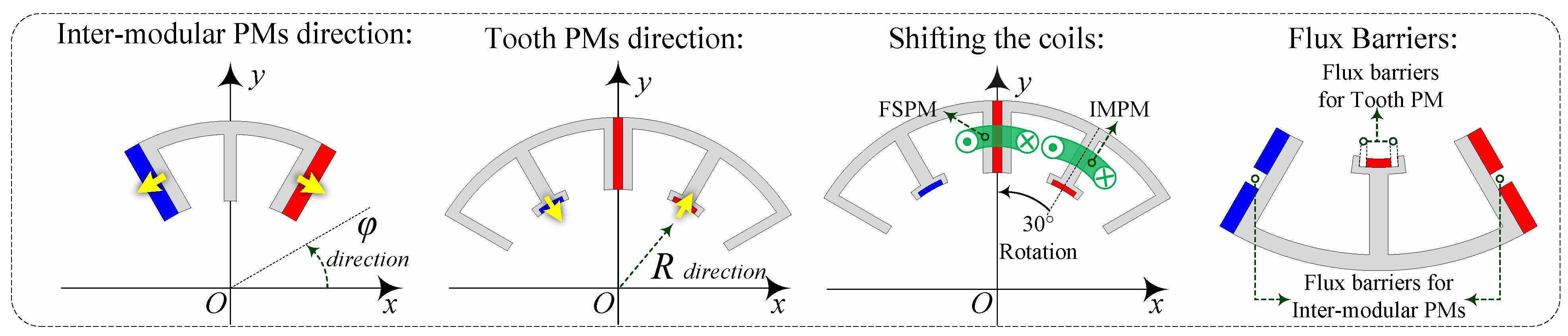
Taking into account the increasing attention given to stator–PM motors that utilise multiple PM arrangements, this paper introduces an innovative design process for synergistic stator–PM motors that leverages the advantages of various PM configurations. Based on the PM placement in stator–PM motors, PM arrays can generally be classified into three categories:
Flux switching (FS): Tangentially magnetised PMs are sandwiched between the armature coils.
Biased flux (BF): Tangentially magnetised PMs are positioned between the stator poles.
Flux reversal (FR): Radially magnetised PMs are mounted on the surface of stator poles.
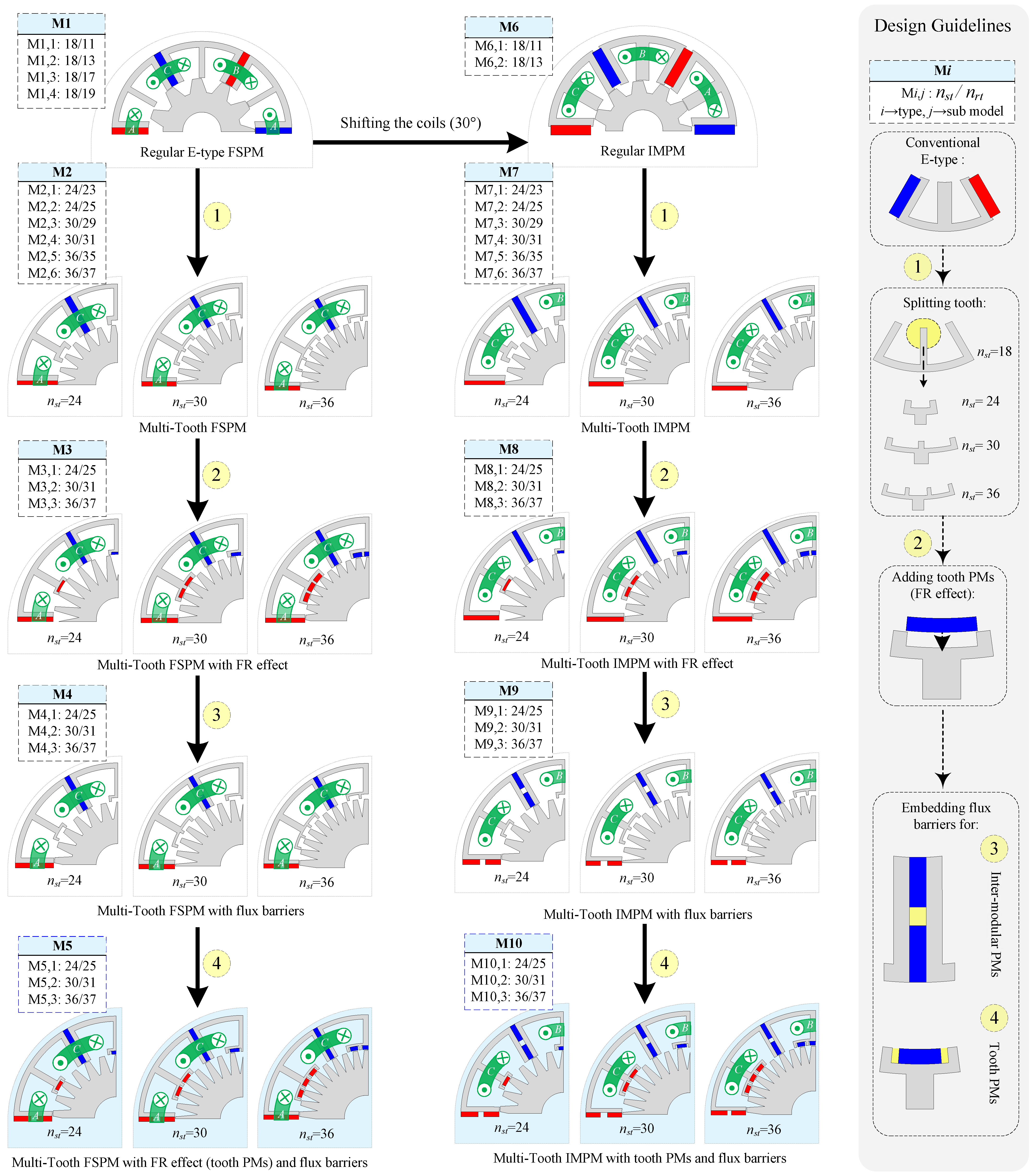
To initiate the design process and develop the final proposed motors, an E-type (E-core) FSPM is selected as the starting point due to its high PM torque density and low ripple [
19,
20]. Additionally, to leverage the flux-concentrating effect of the E-type structure, an inter-modular PM (IMPM) machine is introduced by shifting the FSPM’s armature coils by 30° and employing the BF effect instead of the FS effect [
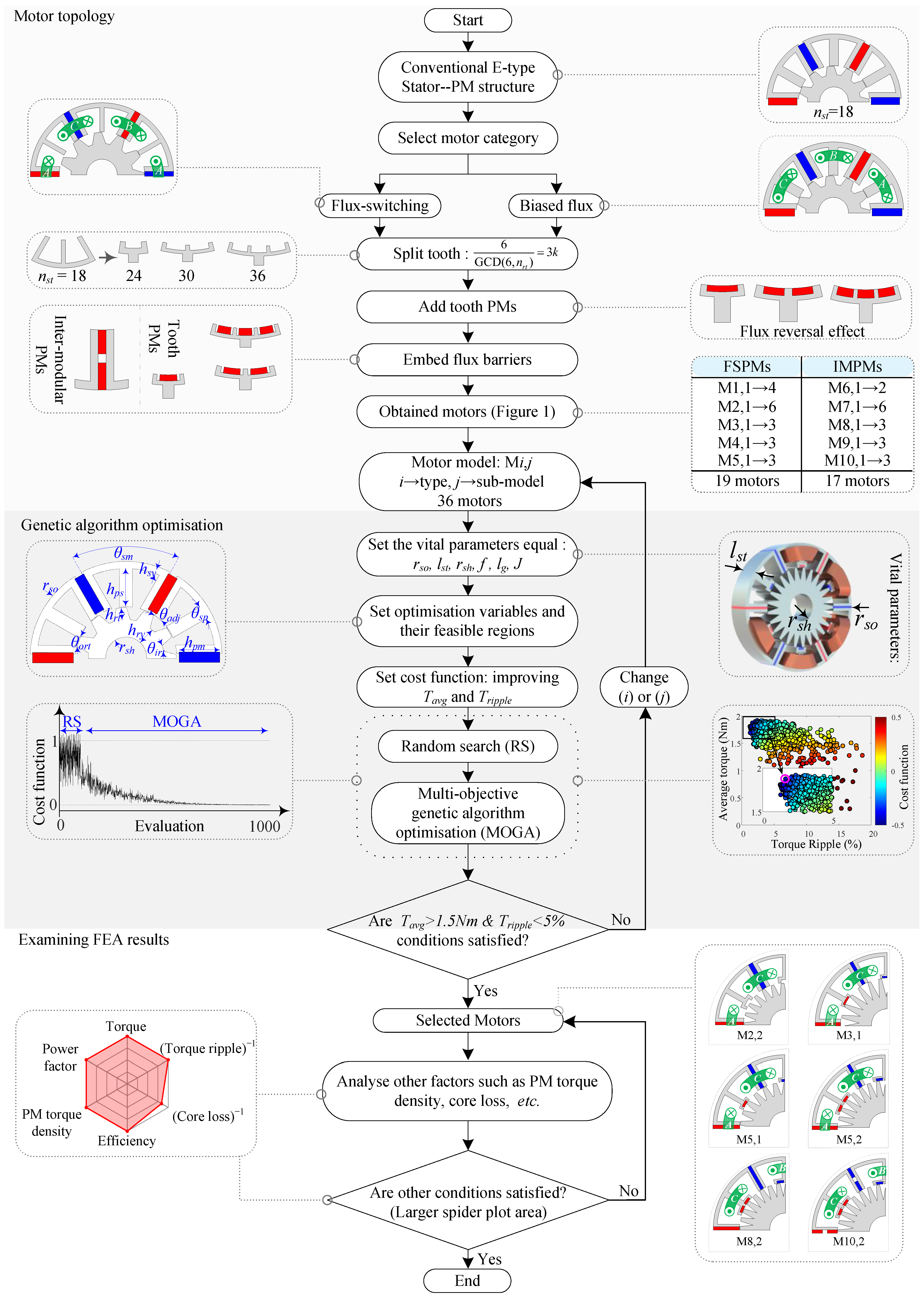
14]. Based on these two benchmark topologies (the E-type FSPM and IMPM), we proceed with the design process, which is fully outlined in
Figure 1. Each design step is applied to both groups (FSPM and IMPM). The first step of the design procedure is to split the teeth and obtain the multi-tooth machines with the feasible stator/rotor pole combinations. The benchmark FSPM and IMPM have 18 stator teeth numbers (
) and can have different rotor teeth numbers (
). The selection process of the optimised multi-tooth structures is investigated in
Section 4. Also, since each model can have different numbers of stator and rotor teeth, they are identified using the notation M
and are illustrated in
Figure 1.
The next step is to add the tooth PMs, introducing the FR effect to the machines. Tooth PMs are placed on top of the middle teeth of the E-core modules. This step integrates the FR effect into the FSPM or IMPM structure, combining the advantages of both PM arrays within the motors. Additionally, the tooth PMs are sandwiched between the iron core, paralleling their flux with that of the armature coils. This parallel flux path reduces the risk of demagnetisation compared to conventional FRPMs [
26]. Adding the FR effect to the motors significantly improves the torque production due to the increase in air gap flux density.
Additionally, another novel design approach is to embed flux barriers for each PM array (for inter-modular or tooth PMs). The main goals of embedding flux barriers for the PMs, which represents the next and final step in the design process, are as follows:
The embedded flux barriers replace part of the PM with air, resulting in a reduction in PM volume.
The flux barriers help lower leakage flux and enhance torque production.
The flux barriers also increase the contact surface of the PMs with the air, improving thermal management.
The impact of embedding flux barriers and their improvements is investigated in
Section 3 through both analytical and FEA results. By applying each step to both groups (FSPM and IMPM), a total of 10 general models (M
i) are obtained. Each model has different sub-models (with varying stator/rotor pole combinations). By considering all the sub-models and feasible M
combinations, a total of 36 motors are obtained. Each process and motor model is explained visually in
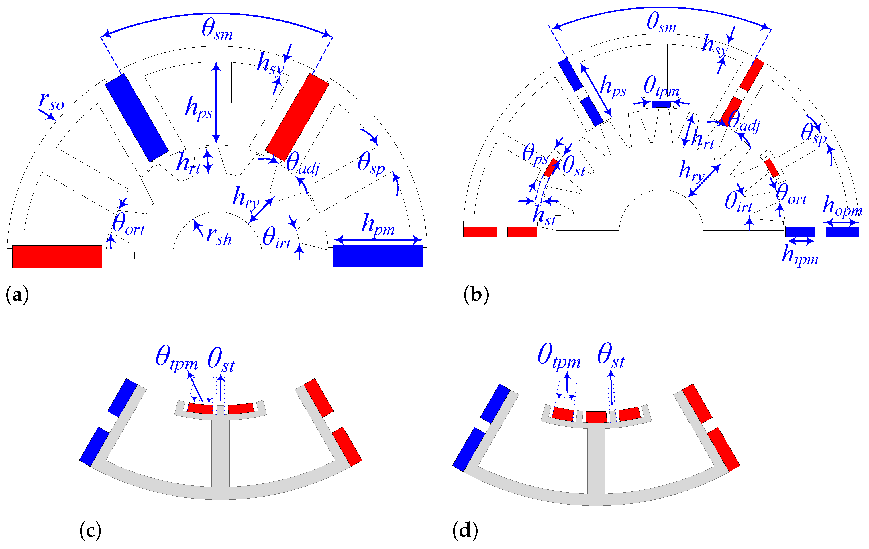
Figure 1. Additionally, the PM magnetisation direction and other design details are shown in
Figure 2. It is worth mentioning that, except for the M1 and M6 (regular FSPMs and IMPMs) models, all other models (and sub-models) are new (30 motors). The promising motors are identified through a decision-making process at the end of the comprehensive FEA.
4. Optimisation
Based on the methodology steps shown in
Figure 1, various topologies (M
) are obtained, and all structures are optimised to have a fair comparison and decision-making process. The methodology process, optimisation, and decision-making based on FEA for all structures are generally illustrated in
Figure 12.
The E-type structure with an inter-modular PM is selected as the starting point thanks to its flux-concentrating effect and highly efficient topology [
20]. In the next step, by choosing the stator–PM category (armature winding configuration), motors with different stator/rotor pole number combinations are obtained for each category. The feasible slot/pole combinations that ensure a balanced m-phase back-EMF can be characterised as follows [
5]:
where
,
, and m demonstrate the stator pole number, rotor teeth number, and number of machine phases. Also, as shown in (
12) and by the key parameters (
and m = 3), the ratio of the
to the greatest common divisor (GCD) of
and
must be a multiple of three (m = 3 and
k is an integer).
Given that, in this relationship,
(the number of stator teeth) does not influence the selection of the number of rotor teeth (
), the numbers of stator teeth are chosen as 24, 30, and 36 based on the motor’s structure, and a higher stator teeth number cannot be selected due to manufacturing considerations. These are paired with various feasible rotor tooth numbers. To achieve better performance (i.e., reduced torque ripple), the numbers of stator and rotor teeth should not differ significantly. The feasible pole number combinations for each motor model are demonstrated in
Figure 1. In the next step of the design process, the tooth PMs and flux barriers are added to the optimal structures obtained in the previous steps (for each stator teeth number structure). This implies that optimisation is performed at each stage initially, and the optimised motors (for each number of stator teeth) advance to the next stage. In other words, at each stage, the design is optimised, and subsequent steps are then applied to the motor. This approach accelerates the optimisation process by eliminating undesirable structures at each stage and enables more precise decision-making. This design and optimisation procedure results in 36 different structure optimisations.
To have a fair optimisation process for all motors, the vital parameters such as stator outer radius (
), stack length (
), shaft radius (
), frequency (
f), air gap length (
), and current density (
J) are set to be the same. Then, optimisation variables with their feasible regions are defined. The optimisation variables for each structure are shown in
Figure 13. Also, the cost function (CF) is expressed in Equation (
13), which is the same for the optimisation of all motors.
The optimisation process is guided by the cost function defined in Equation (
13), with a margin value of 1.1 established as the threshold, which the process seeks to minimise. The coefficients
and
, which denote the weighting factors for the average torque and torque ripple, respectively, are set to 0.85 and 0.15. The target values, denoted as
and
, represent the desired average torque and torque ripple, specified as 1.5 Nm and 5%, respectively. In contrast,
and
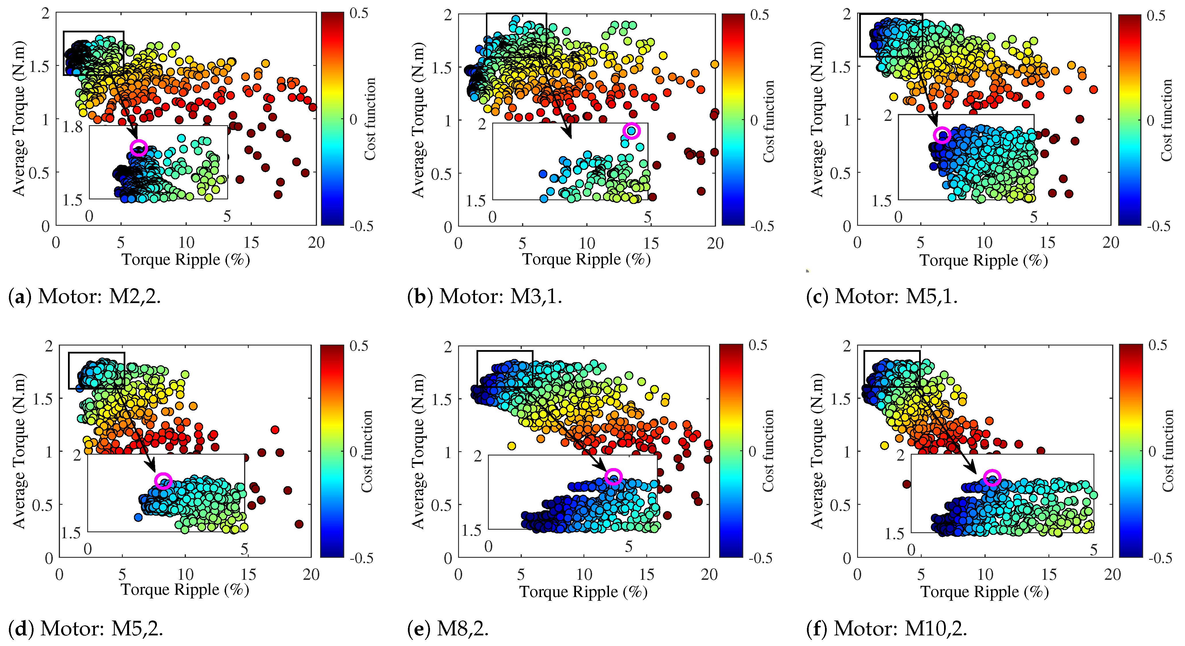
correspond to the computed average torque and torque ripple for each iteration. In the optimisation process for each motor, approximately 1000 samples are generated. The optimisation profile for the six motors with the best performance is presented in
Figure 14. Based on the cost function, each sample is evaluated, and the optimal region (Pareto front) is identified. This process is similarly applied to the other motors. Additionally, in
Figure 14, the optimal sample and structure are illustrated. Additionally, the convergence profile of the cost function for the optimisation setup is illustrated in
Figure 12. The first 100 samples are generated using a random search (RS) genetic algorithm, while subsequent samples are developed through multi-objective genetic algorithm (MOGA) optimisation.
The optimisation results for the different motor models (M
) are listed in
Table 1. Based on the literature and related studies, two conditions,
and
, are established as the necessary conditions required for motors to advance to the FEA examination stage. Six motors, namely (M2,2), (M3,1), (M5,1), (M5,2), (M8,2), and (M10,2), satisfy the specified conditions. Furthermore, two motors, (M5,1) and (M10,2), exhibit the lowest cost function (CF) values in their respective categories. The key design parameters for the six advanced motors are listed in
Table 2. Also, the values of the optimisation variables for the six advanced motors, demonstrated in
Figure 13, are listed in
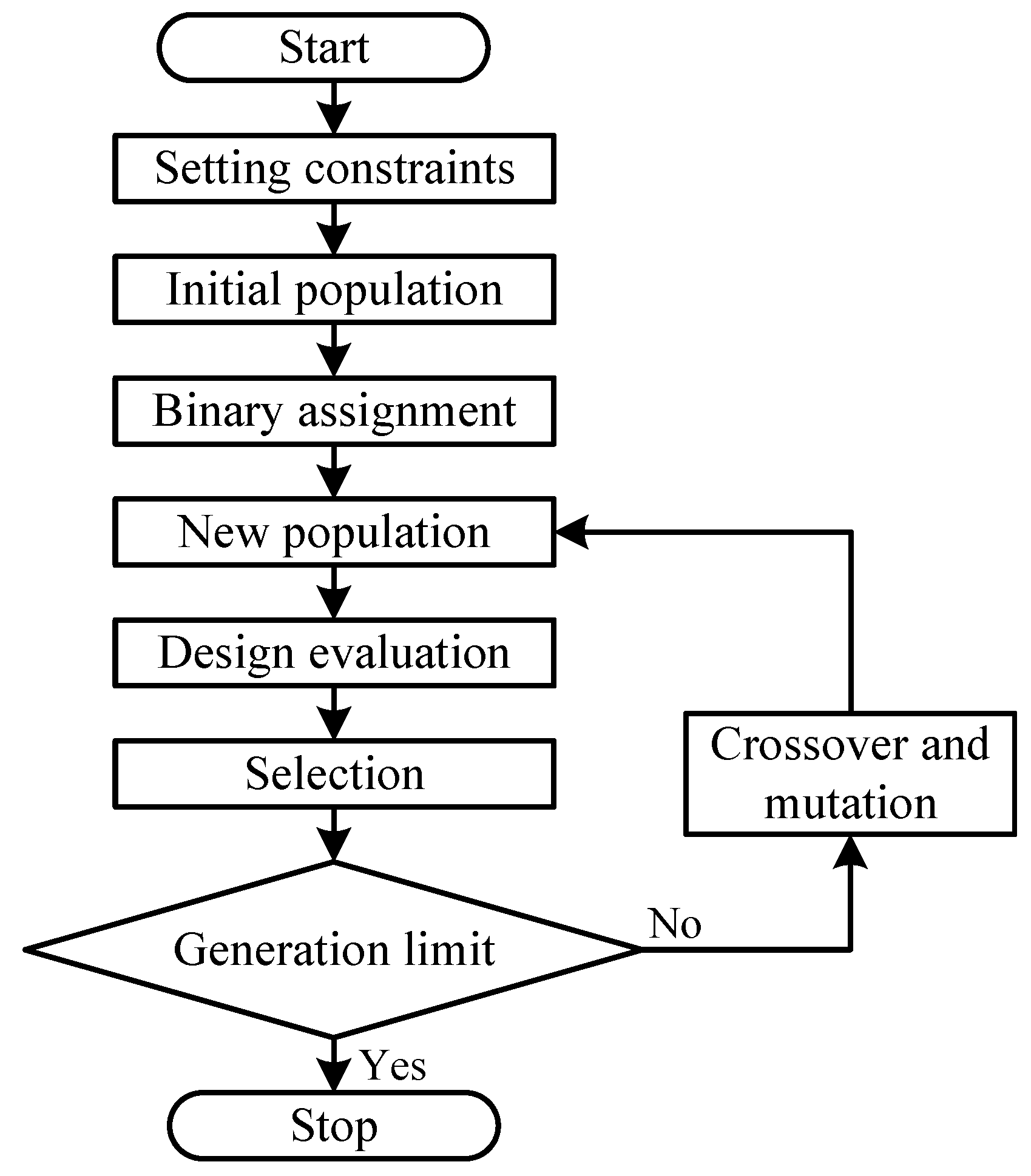
Table 3. The optimisation is carried out using a GA, the framework of which is illustrated in
Figure 15. A detailed overview of the applied constraints within the GA process is presented in
Table 2.
The GA optimisation is inspired by natural selection and operates through three primary mechanisms: mutation, crossover, and selection. Mutation and crossover introduce variation to the population, helping avoid local optima and improving global search capabilities. The selection mechanism identifies the most promising candidates in each generation based on weighted objective functions. In this study, the weight assigned to maximising the average torque is 0.85, while minimising torque ripple is weighted at 0.15, emphasising torque improvement with consideration for ripple. The process starts with 30 initial individuals, evolves through generations of 20 individuals each, and is limited to 20 generations. The GA setup includes 100 initial samples generated via Screening, with 50 new samples per iteration. A high crossover probability of 0.98 and a low mutation rate of 0.01 are used to ensure diversity and avoid local optima. The optimisation runs for a maximum of 30 iterations, with convergence checked using a stability threshold of 0.0001. Up to 70% of individuals can remain on the Pareto front, and the total estimated number of variations is 1600.
A set of parametric simulations is first conducted to determine the feasible regions for all design parameters, as shown in
Table 4. This initial study helps identify the critical ranges with the highest optimisation potential. Sensitivity analysis is then performed by varying the objective weights, confirming that the (0.85, 0.15) combination offers the best trade-off between torque maximisation and ripple reduction. MOGA results also start with the critical regions, showing better convergence and more reliable outcomes.
5. Finite Element Analysis Results
In this section, the next phase of the decision-making procedure is conducted on the motors advancing to this stage (see
Figure 12). Six advanced motors will be compared by using FEA under two conditions: (1) no load and (2) full load. In addition to the average torque and torque ripple comparison which was analysed in the previous section, other factors such as back-EMF, cogging torque, flux density distributions, and overload profiles are also analysed in this section.
5.1. No-Load Analysis
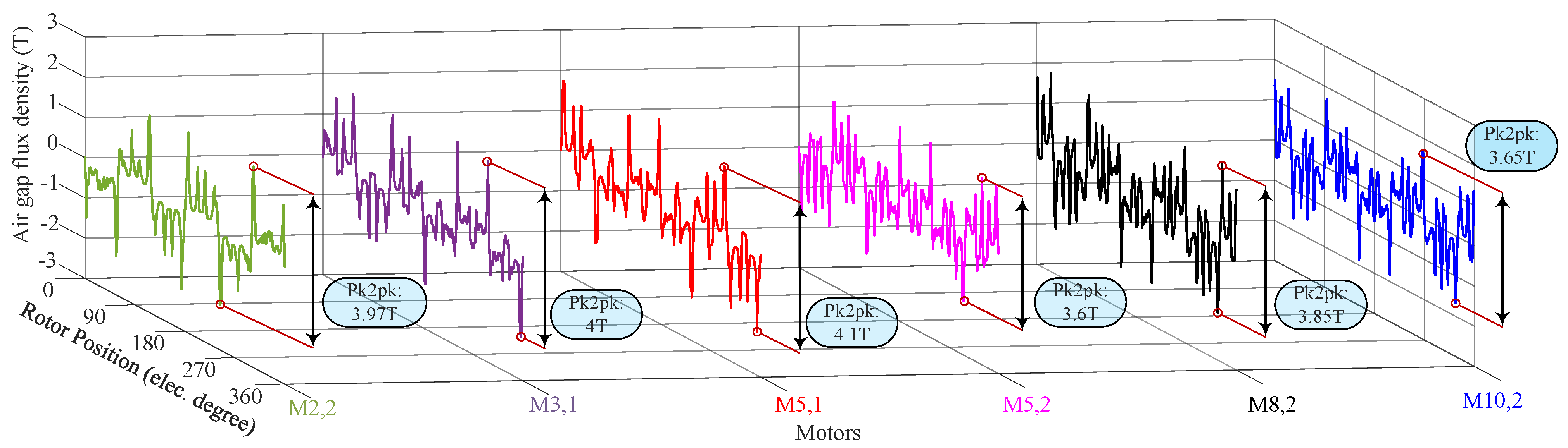
The no-load air gap flux density versus the rotor position curve of the motors comparison is illustrated in
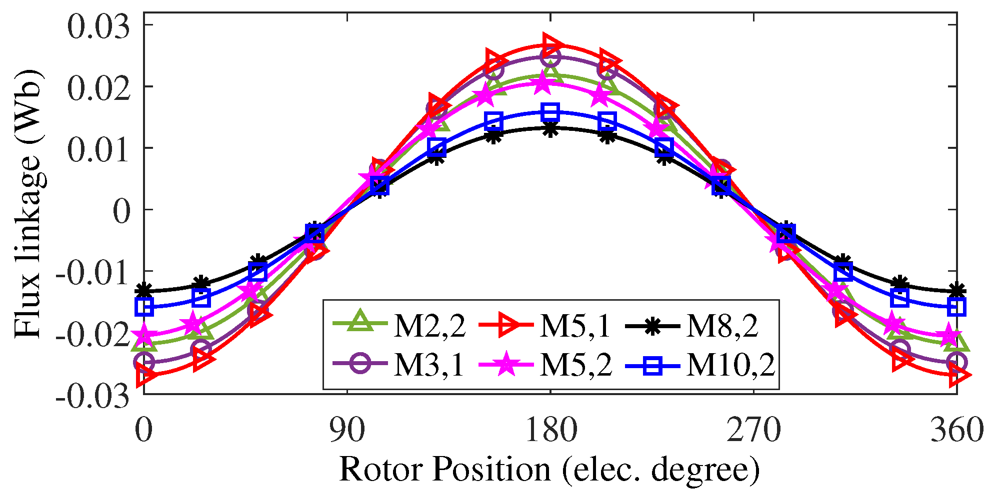
Figure 16. It is demonstrated that the (M5,1) topology, which incorporates embedded flux barriers for both tooth and inter-modular PMs, exhibits the highest peak-to-peak no-load air gap flux density compared to motors with higher PM volumes, underscoring the impact of flux barriers. This increase in air gap flux density results in higher flux linkage for the (M5,1) motor compared to other structures, as shown in
Figure 17.
The highest back-EMF generation among the motors is achieved by (M5,1), with a value of 27.7 V, shown in
Figure 18a. Additionally, (M3,1) exhibits an identical back-EMF profile. However, unlike (M5,1), this structure lacks flux barriers. All back-EMF waveforms have nearly sinusoidal curves with lower than 5% total harmonic distribution (THD), and M5,1 has the lowest THD at 1%. Considering the generated back-EMF and THD, the (M5,1) motor demonstrates the best performance. The harmonic distribution of the back-EMF of the motors is shown in
Figure 18b.
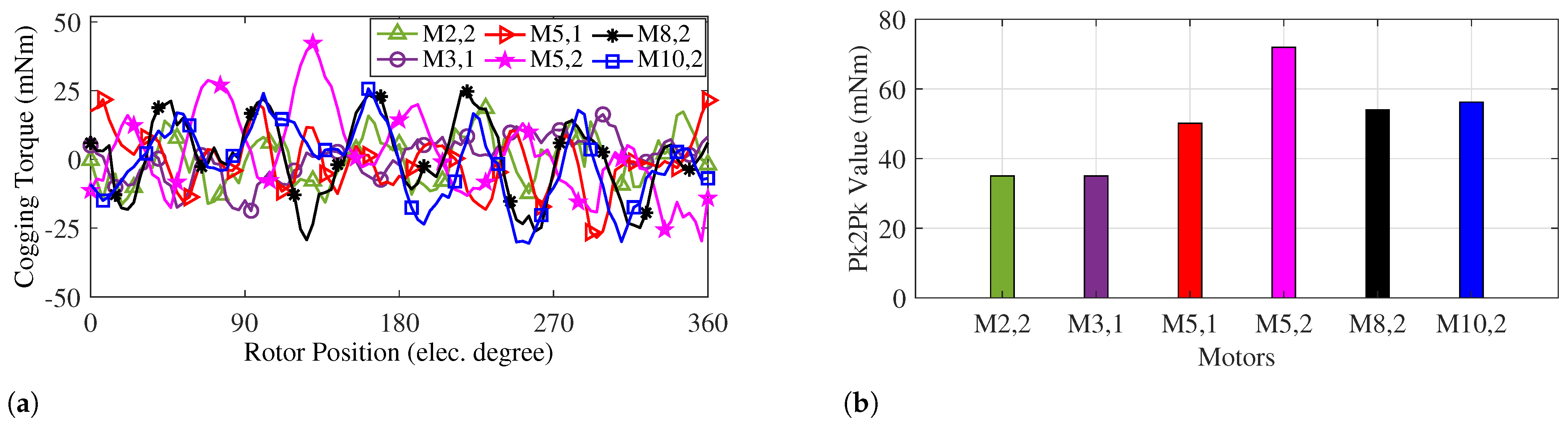
The cogging torque profiles of the motors are presented in
Figure 19a. Although the cogging torque profiles have an average value of approximately 0 Nm, a comparison of their peak-to-peak (pk2pk) values is shown in
Figure 19b. All structures exhibit a peak-to-peak cogging torque below 80 mNm, which is considered an acceptable value.
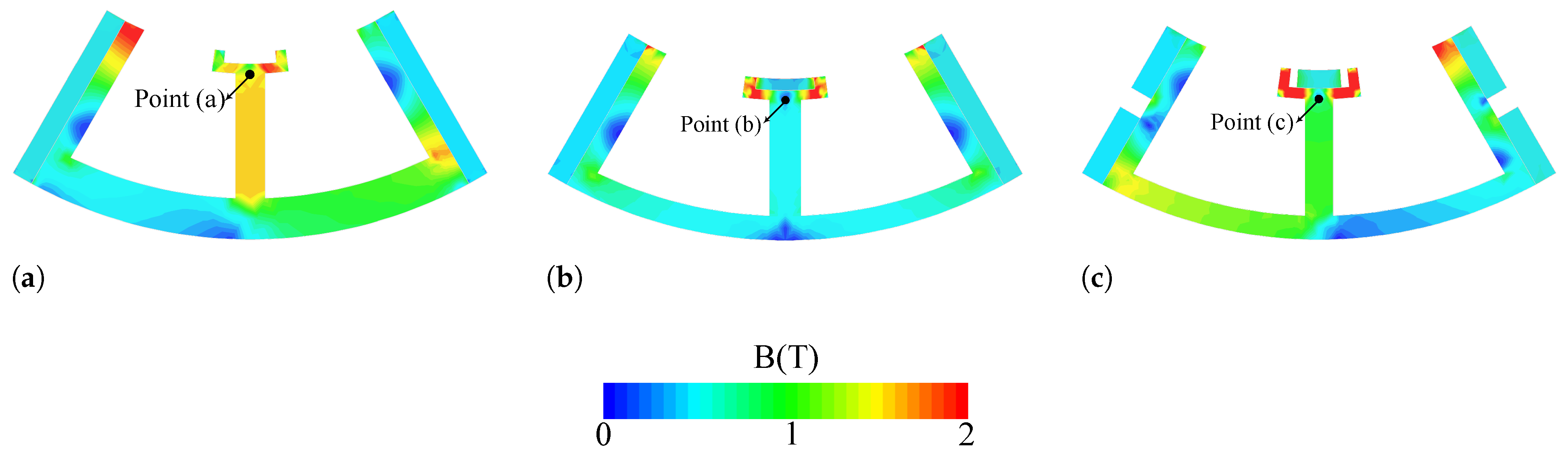
The flux density distribution of three different kinds of structure (with inter-modular PMs only, with tooth and inter-modular PMs, and with embedded flux barriers) under no-load conditions is shown in
Figure 20. By comparing
Figure 20a,b, which illustrate the impact of tooth PMs and the interaction between both PM arrays, it is observed that the stator core flux density decreases. Furthermore, by embedding flux barriers and eliminating flux leakage, the stator core exhibits a further reduction in flux density. This also implies the effects of adding tooth PMs and flux barriers, respectively.
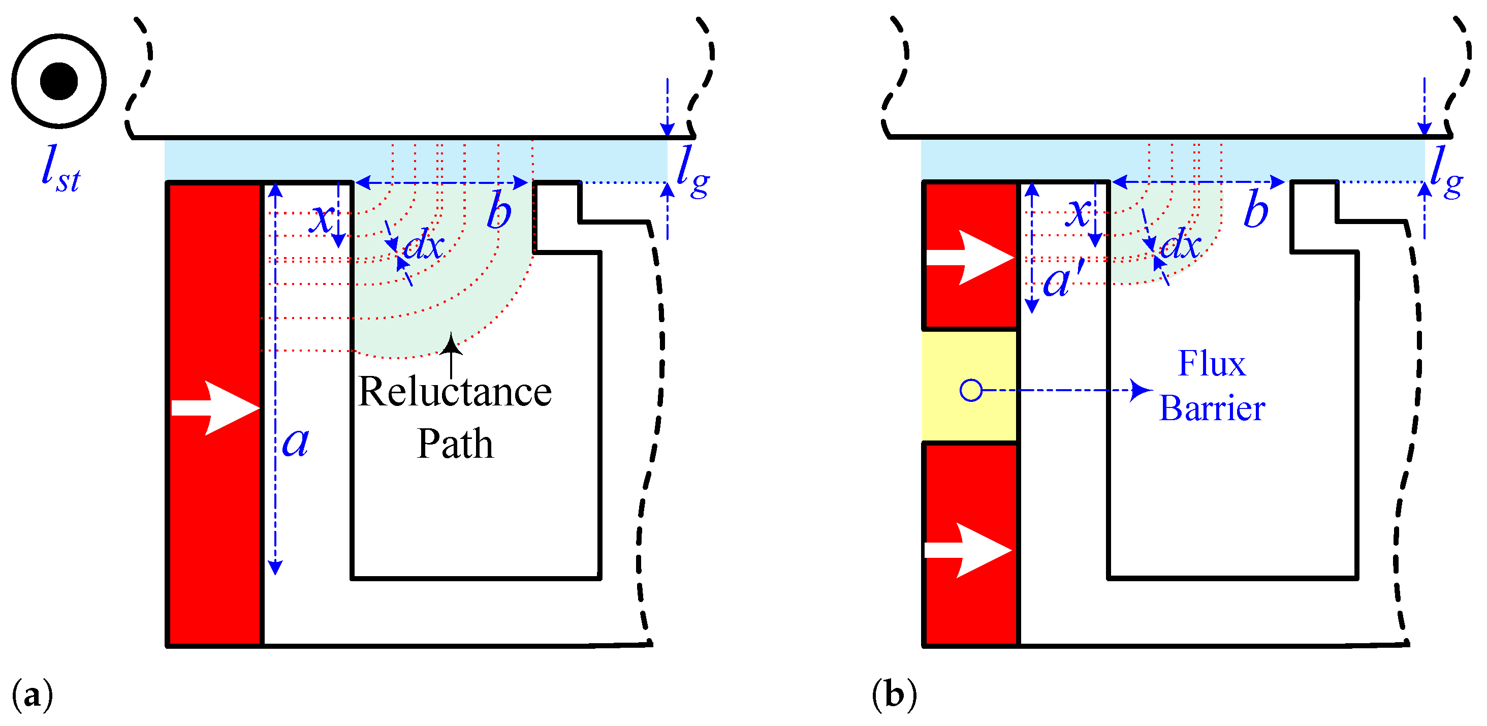
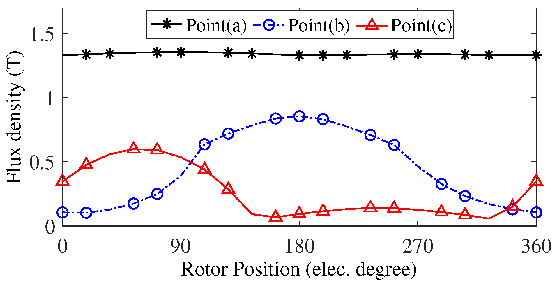
For a more detailed investigation, the flux density of points a, b, and c is selected in an E-type motor with only inter-modular PMs and with both PM arrays and embedded flux barriers, illustrated in
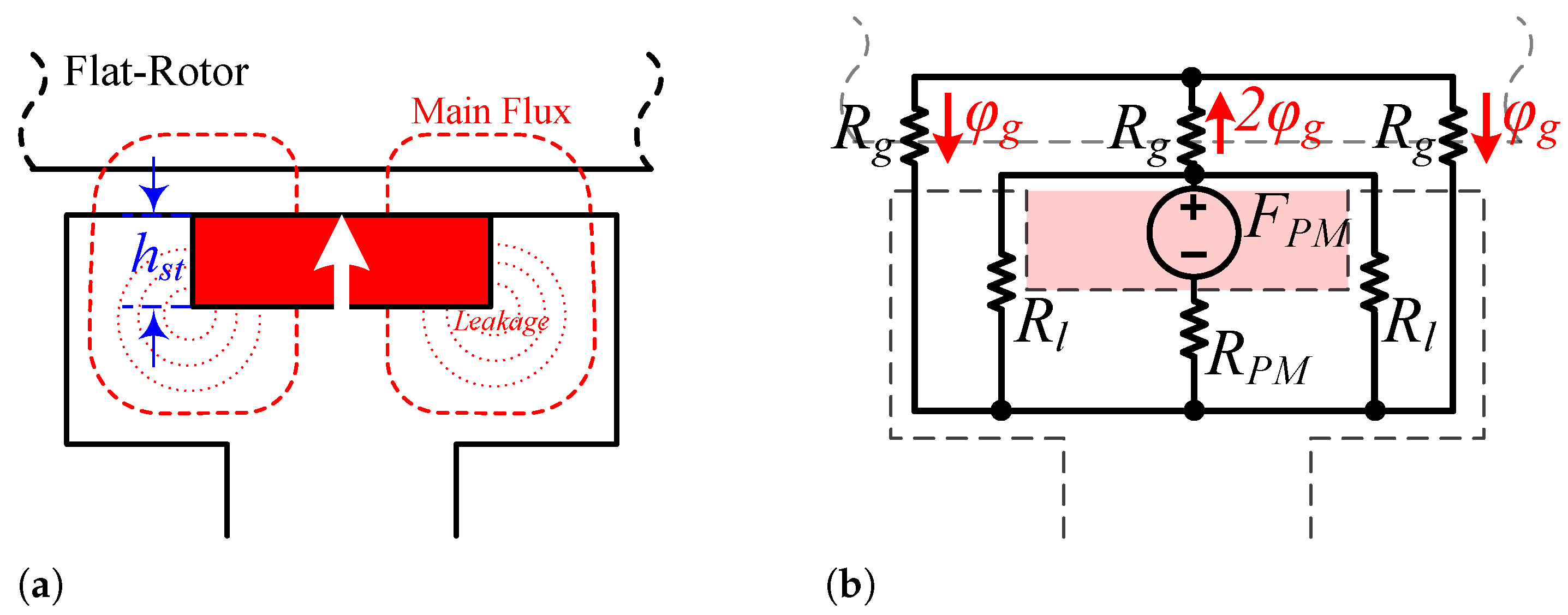
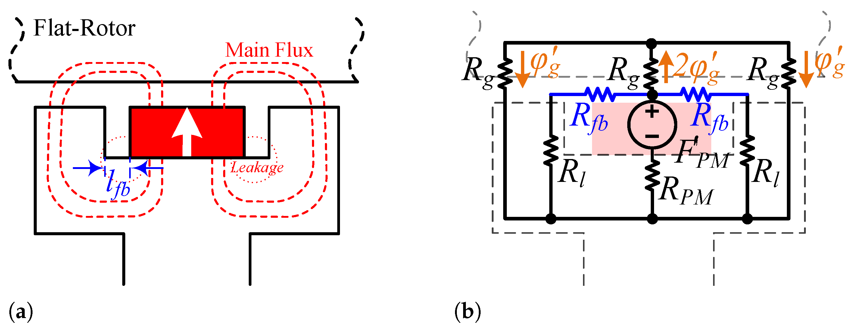
Figure 21, respectively. Points “a”, “b”, and “c” exhibit profiles with 1.3 T, 0.5 T, and 0.3 T average values, respectively. Adding tooth PMs to the conventional E-type structure results in a 62% reduction in stator core flux density, thereby reducing the risk of saturation. Also, embedding the flux barriers decreases by 77% and 40% compared to the topologies without tooth PMs and with tooth PMs.
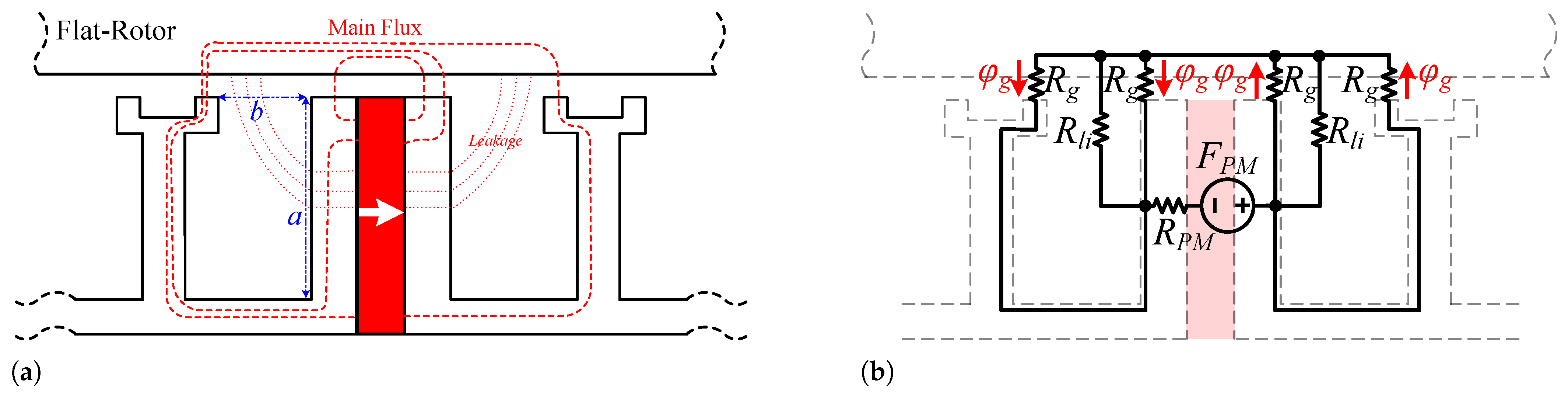
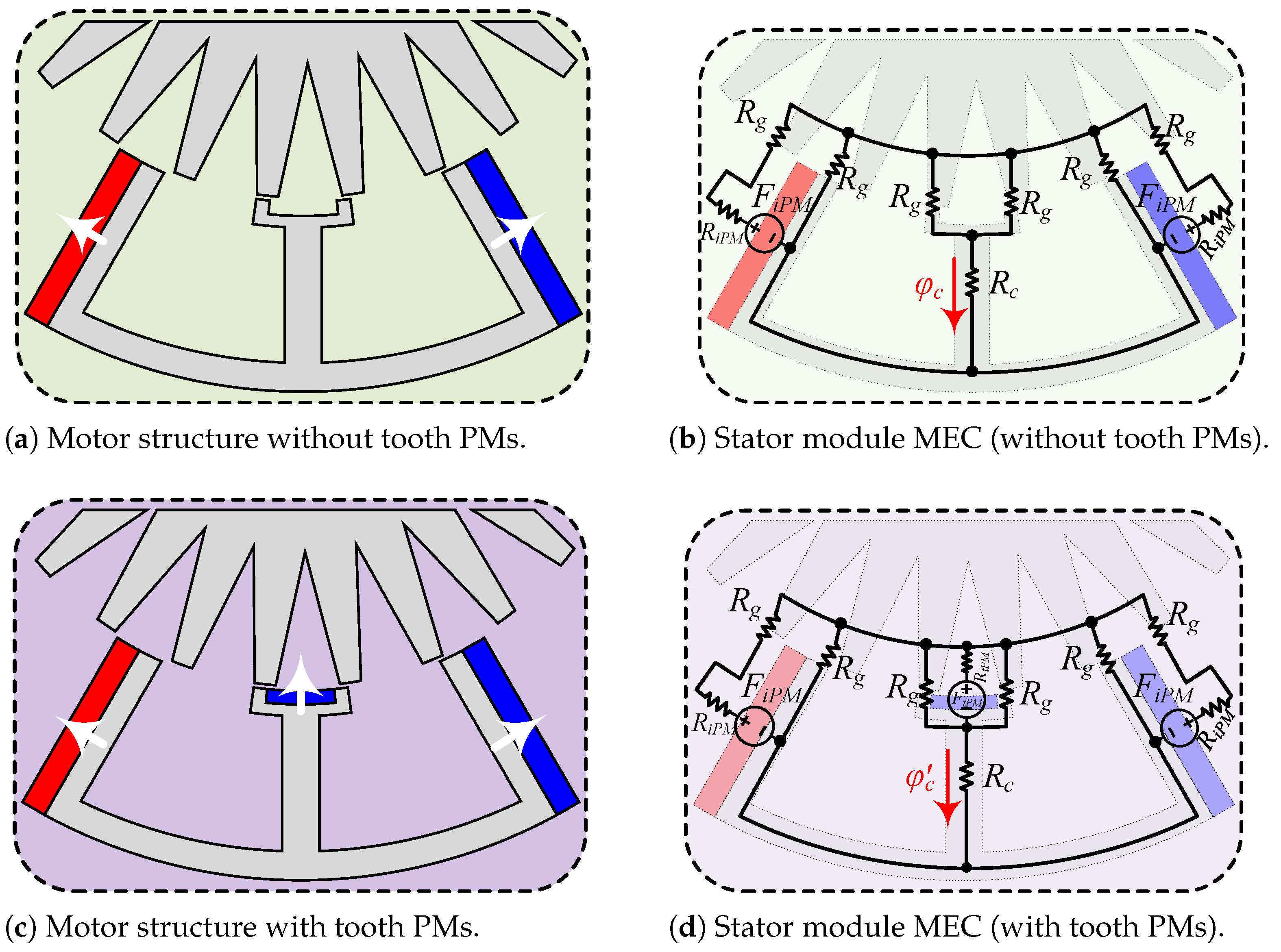
To investigate the analytical reasons behind this improvement, one module of the motor, both without tooth PMs and with tooth PMs, along with their corresponding MECs, is presented in
Figure 22. The stator core flux for the conventional structure (
) is expressed in Equation (
14). Additionally,
represents the flux generated just by the inter-modular PMs.
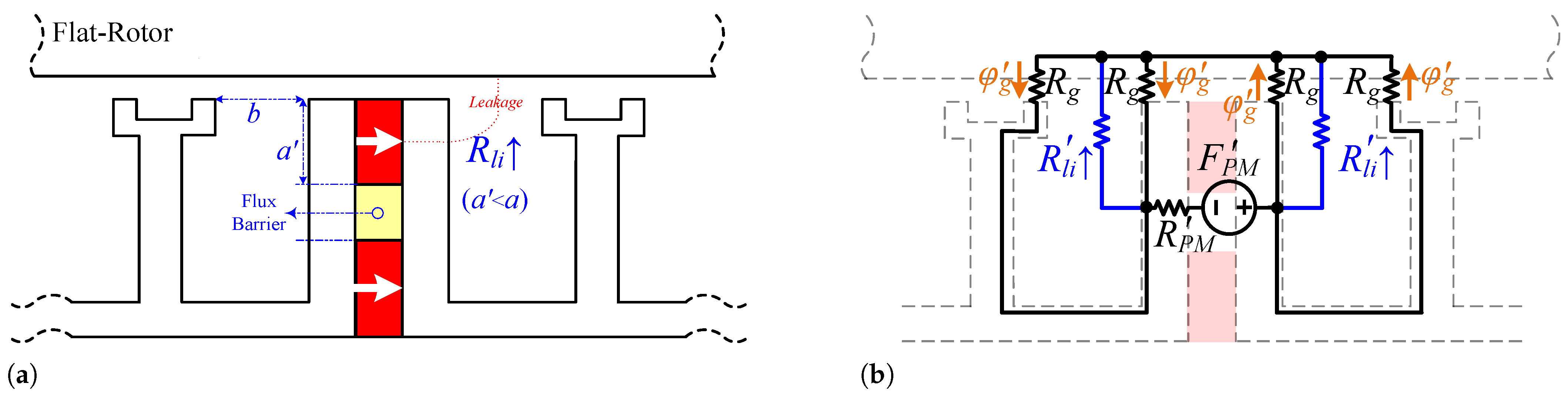
Due to the opposing directions of the flux generated by the inter-modular and tooth PMs within the stator core, the flux (flux density) in the stator core is reduced. Analytically, this decrease can be expressed by Equation (
15):
The stator core flux density with tooth PMs, denoted as (), exhibits a lower value compared to , resulting in a reduced risk of saturation and improved overload performance.
5.2. Full-Load Analysis
The full-load results play a crucial role in the decision-making process. Under full-load conditions, the six advanced motors share identical basic full-load parameters to ensure a fair analysis. The vital parameters are listed in
Table 2. Although the motors operate at the same frequency, variations in rotor teeth (pole combinations) among some motors result in different speeds. The speed of the motor
(rpm) considering the rotor teeth number
and frequency
f (Hz) is calculated as 400 rpm and 323 rpm for 25-tooth and 31-tooth rotors, respectively. Additionally, in this stage, the category of motors (armature winding configuration) has a significant effect on their performance compared to under the no-load condition (where the coils are not energised). In addition, to ensure safe thermal management, the current density of motor excitation is selected to be
A/mm
2.
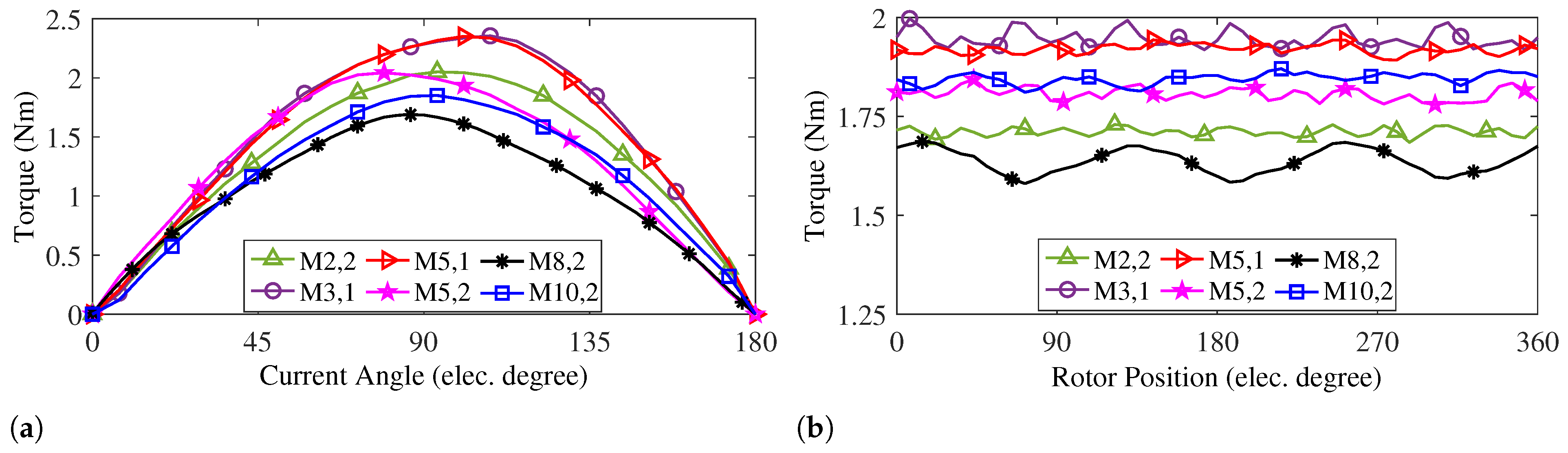
The static and full-load torque profiles of the motors are shown in
Figure 23a and
Figure 23b, respectively. Both (M3,1) and (M5,1) achieve an average torque of 1.9 Nm, but (M5,1) exhibits a 55% lower ripple compared to the other. In third place, (M10,2) has an average torque of 1.85 Nm. The effect of flux barriers for both PM arrays is evident, as structures with embedded flux barriers and tooth PMs demonstrate a torque performance improvement of 46% and 68% compared to the conventional FSPM and IMPM, respectively.
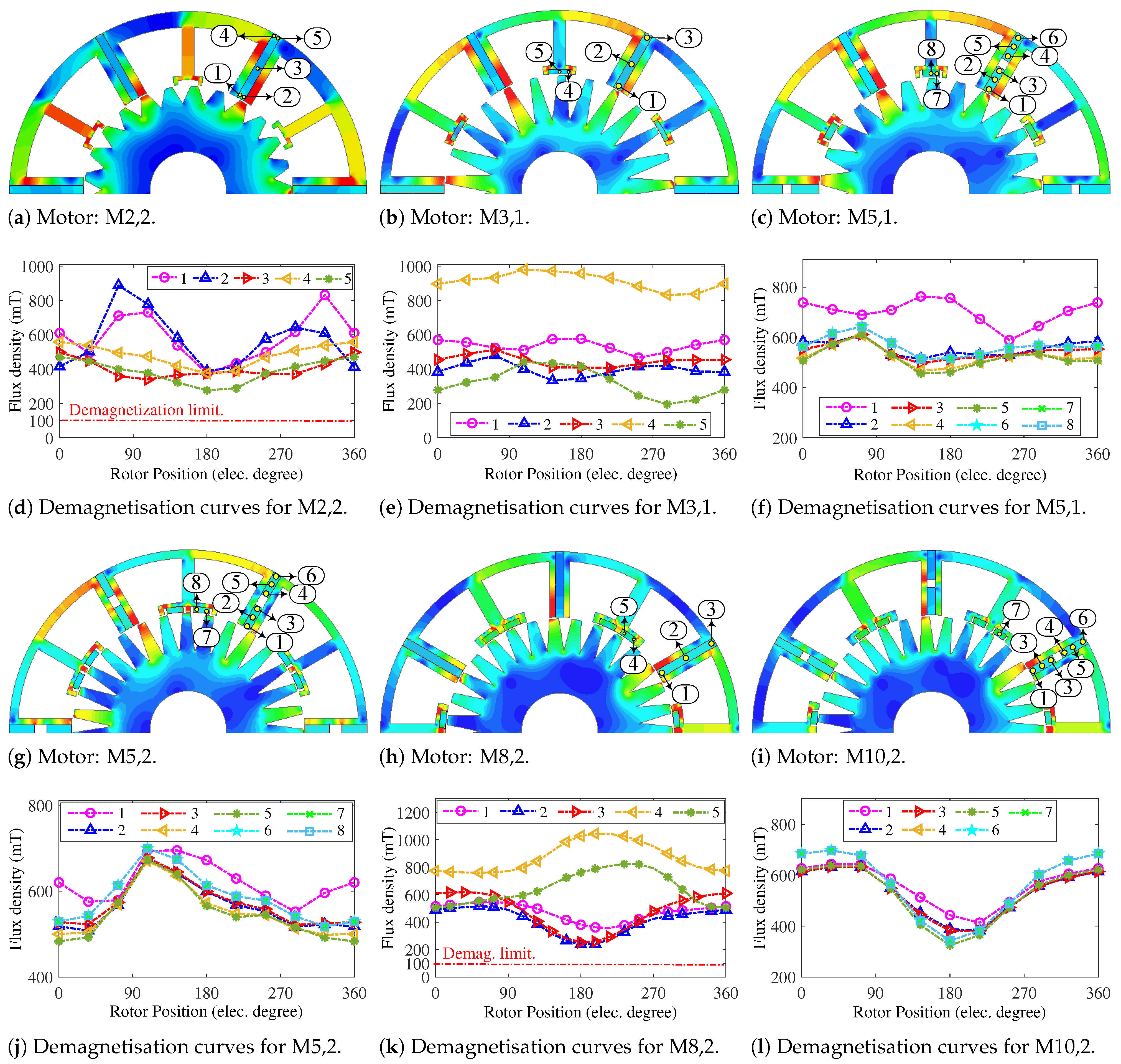
The full-load flux density distribution of the motors, along with their demagnetisation curves, is shown in
Figure 24. The flux density distribution of the motors shows no global saturated region in all six motors. However, by inspecting
Figure 24a,b, the effect of adding tooth PMs to the conventional structure can be seen in the decreasing stator core. Additionally, motors belonging to the IMPM category exhibit fewer red regions compared to FSPM motors.
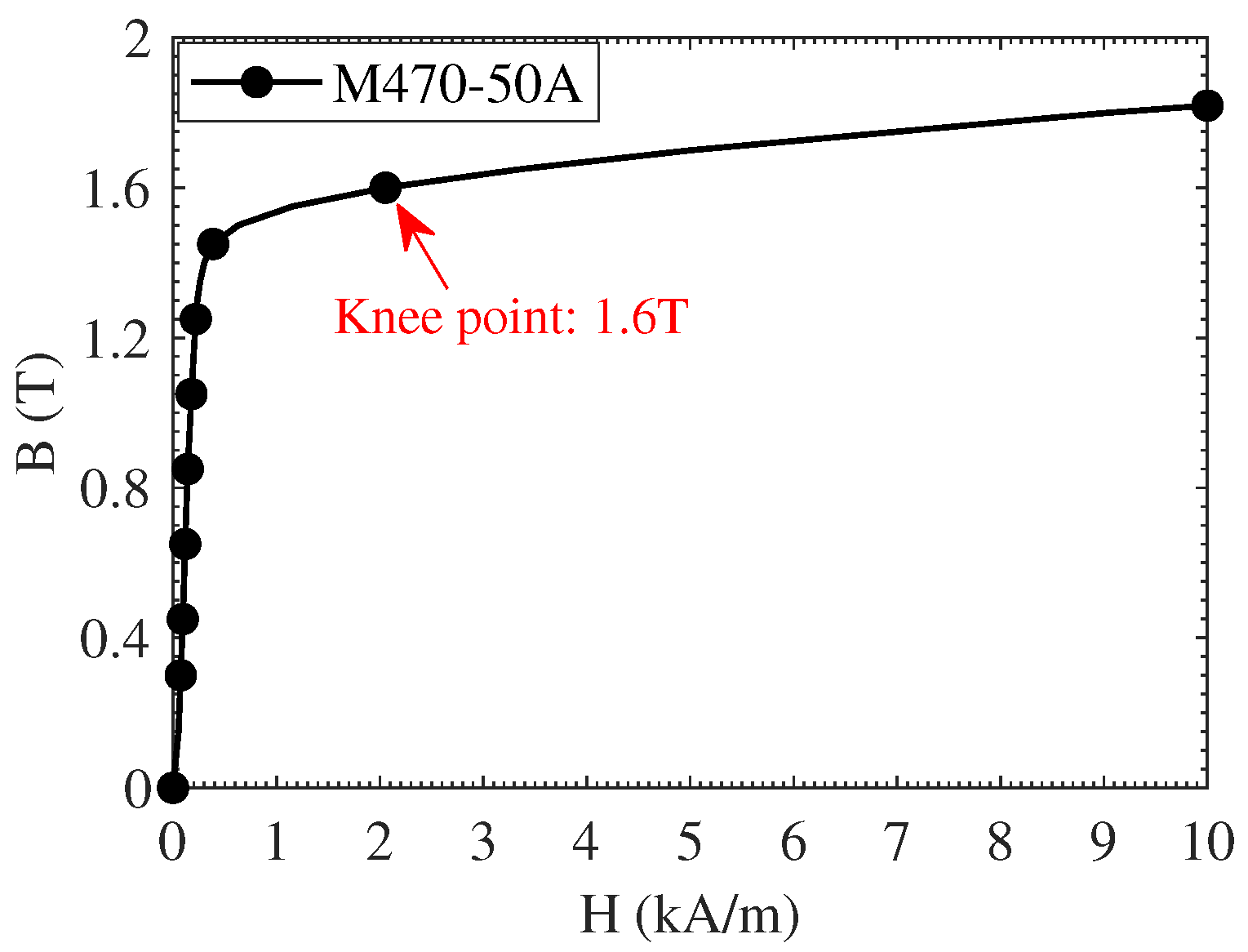
The demagnetisation curves of the motors’ PMs are determined based on the minimum flux density of these PMs, ensuring they do not exceed the demagnetisation limit. By considering the knee point of NdFeB-N42 PM material, which is 0.1 T, no selected points suffer from demagnetisation. The B-H curve of the NdFeB-N42 PM material exhibits a knee point at approximately 0.1 T at 80 °C, which represents a worst-case thermal scenario for the motor under nominal operating conditions. This condition will be further analysed in the following 3D-FEA section. It has been shown that embedding flux barriers reduces the risk of demagnetisation, particularly at points in inter-modular PMs, which exhibit much safer performance. Additionally, tooth PMs operate without demagnetisation risk (or even near their limits). Compared to conventional FRPM machines, this design resolves the traditional demagnetisation issue.
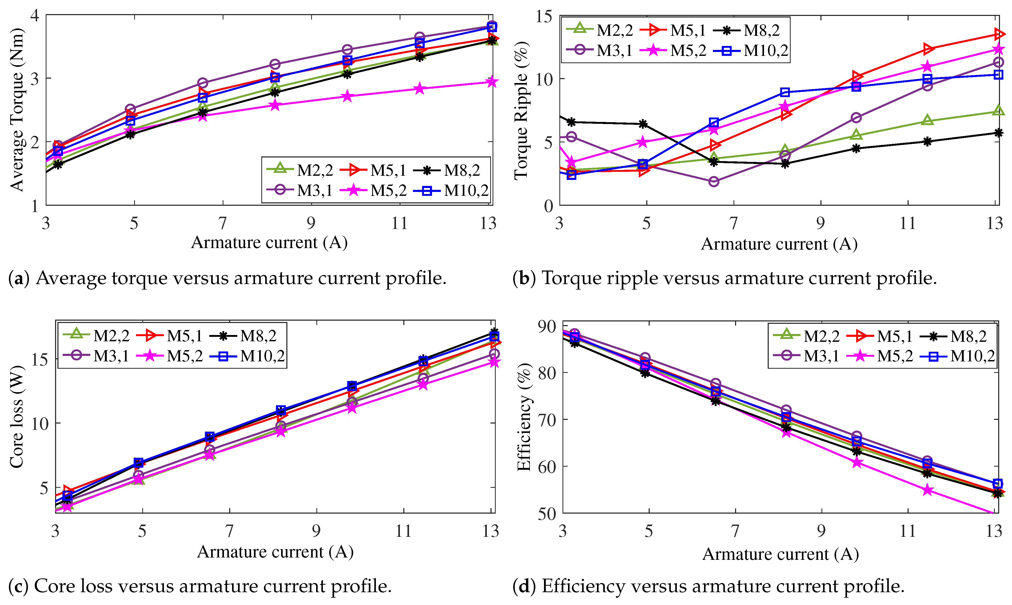
Overload performance analysis of the motors can demonstrate the mechanism of core saturation and the demagnetisation of PMs. Severely degraded performance under overload conditions may serve as an indicator of the obsolescence of these two factors. Considering a current density of 6 A/mm2 and a specified wire diameter (selected as 0.7 mm, though other sizes can also be chosen), the nominal current for the armature winding is calculated to be A. The performance of the overload is analysed at up to four times the nominal condition ( A).
In terms of the average overload torque, as shown in
Figure 25a, all motors exhibit a similar upward trend. No significant drops occur in the profiles; however, some, such as M5,2, may exhibit poorer performance. Additionally, under overload conditions, M10,2 demonstrates a steeper upward slope and superior overload performance. Additionally, the motors exhibit an acceptable torque ripple under overload conditions, with values below 15% (see
Figure 25b). In terms of overload core loss and efficiency, the motors display similar behaviour, as shown in
Figure 25c and
Figure 25d, respectively. However, the issues previously noted regarding the performance of the two motors M10,2 and M5,2 with respect to average torque also apply here. Overall, the performance of all six motors under overload conditions remains highly consistent.
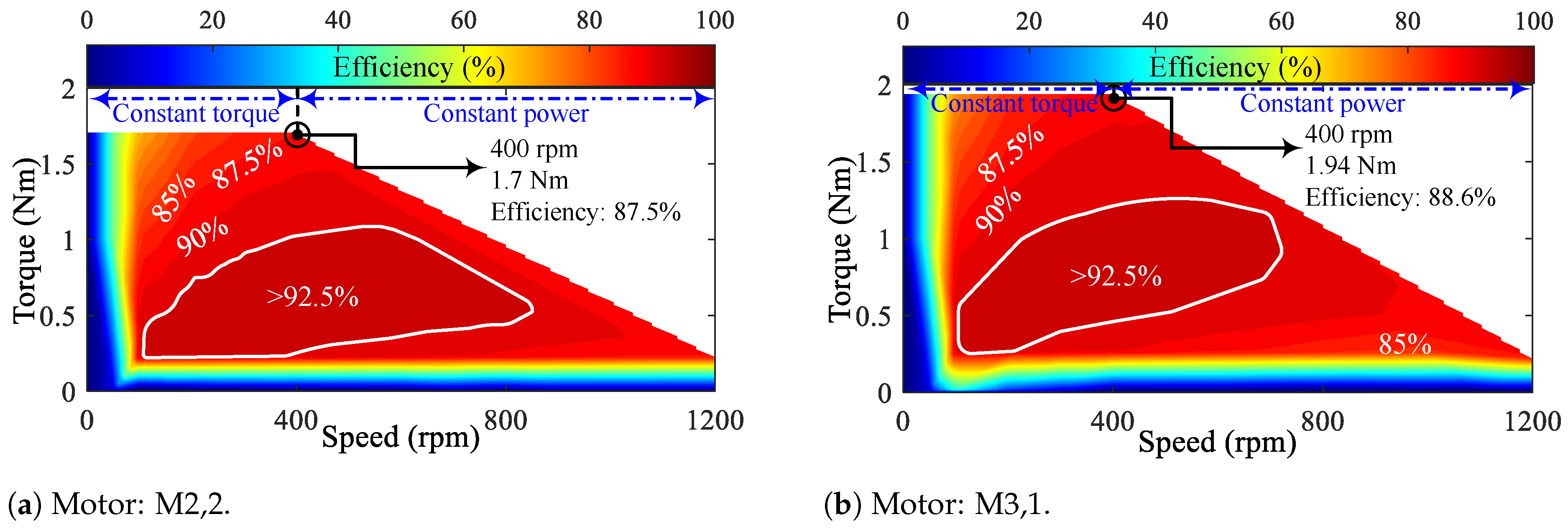
The efficiency maps up to three times the nominal speed (
) of the motors are shown in
Figure 26. Since the motor speeds vary depending on the number of rotor teeth, a portion of the graphs remains empty due to the uniform limits applied across all charts. Furthermore, the regions of constant torque and constant power are also identified based on the nominal operating point. Upon examining the efficiency maps, it can be seen that FSPM motors generally exhibit superior performance compared to IMPM types. Additionally, the high-efficiency regions, where efficiency exceeds 92.5%, are delineated on the maps for all motors. All FSPM-type motors display nearly identical high-efficiency areas within the constant torque region. However, when considering constant torque, M5,2 demonstrates the largest high-efficiency area among the motors. This superiority highlights the influence of flux barriers and tooth PMs compared to the conventional motor (M2,2). Conversely, M8,2, which utilises an IMPM-type design, exhibits the smallest high-efficiency area.
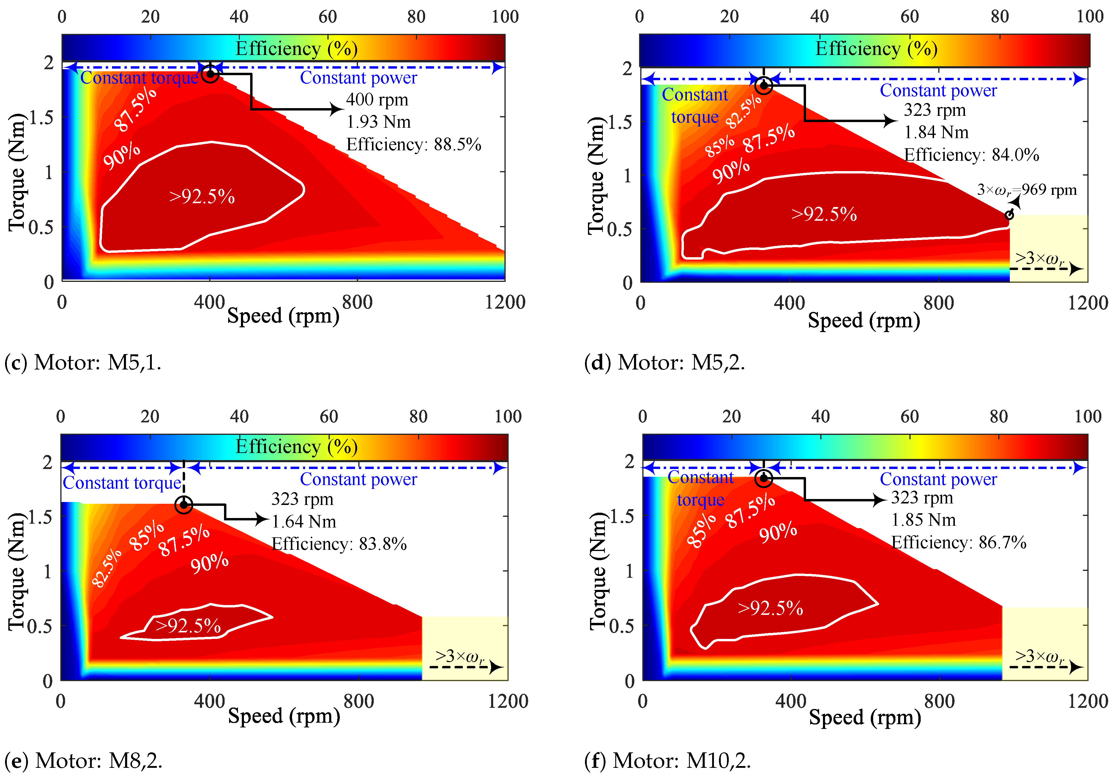
The core loss maps of the motors with a similar procedure as the efficiency maps are illustrated in
Figure 27. The motors M3,1 and M5,1, which produce the highest power, exhibit the largest red areas in terms of core losses compared to the other motors (
Figure 27b and
Figure 27c, respectively). However, overall, all motors demonstrate acceptable core losses below 4 W. Additionally, M5,2 (
Figure 27d), which previously showed the largest high-efficiency region, is also observed here to have areas with lower loss distribution compared to the other motors.
5.3. Decision-Making
In this part, the merits of the novel design procedure are highlighted based on the FEA results and by considering other parameters such as PM torque density and the power factor. The essential parameters—torque, torque ripple, core loss, efficiency, PM torque density, and the power factor—are investigated at the nominal load. The best performances of the motors for each parameter are presented in
Table 5.
Table 5 clearly demonstrates that M5,1 possesses three of the six best performances and holds the largest share among the motors.
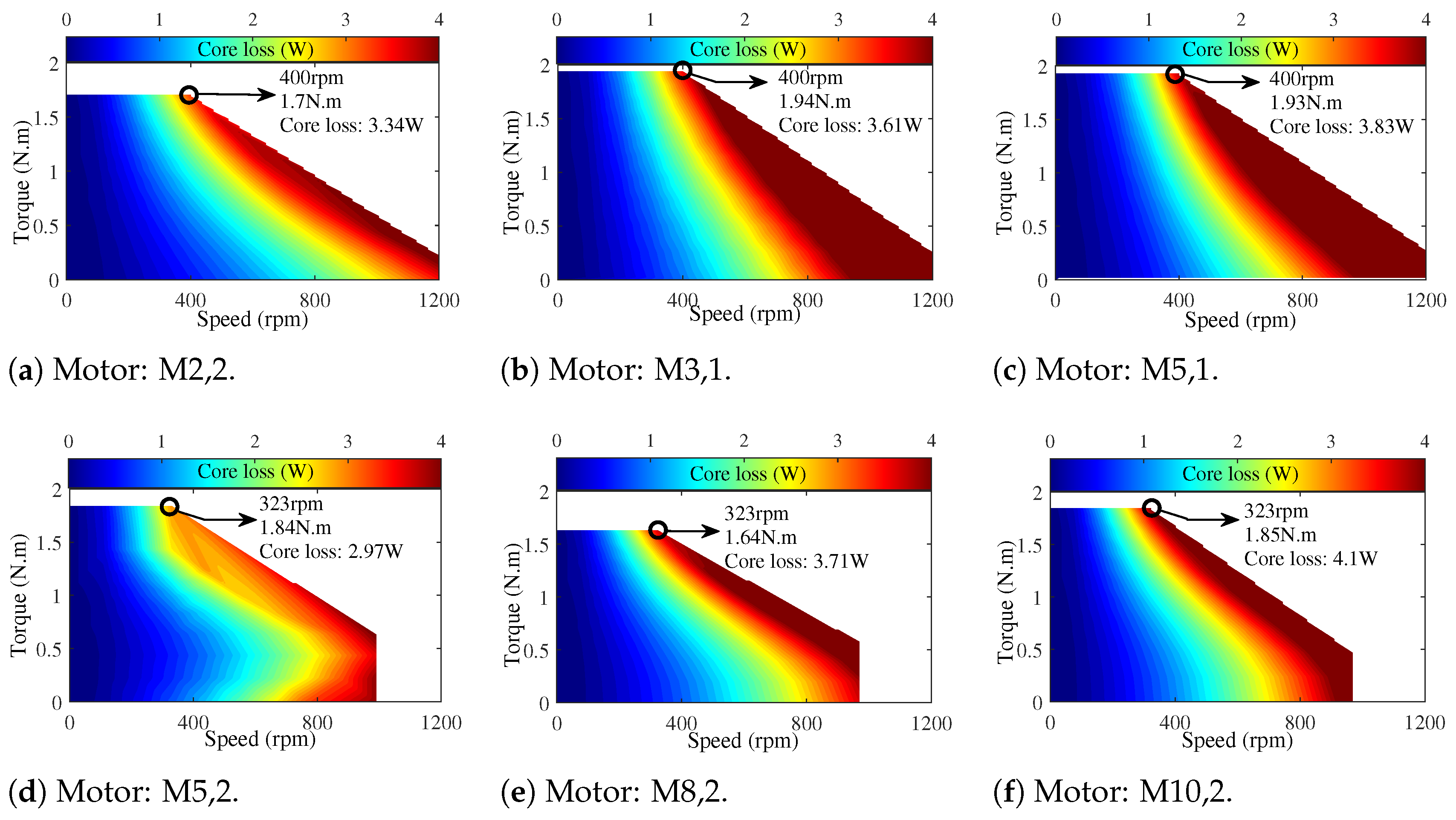
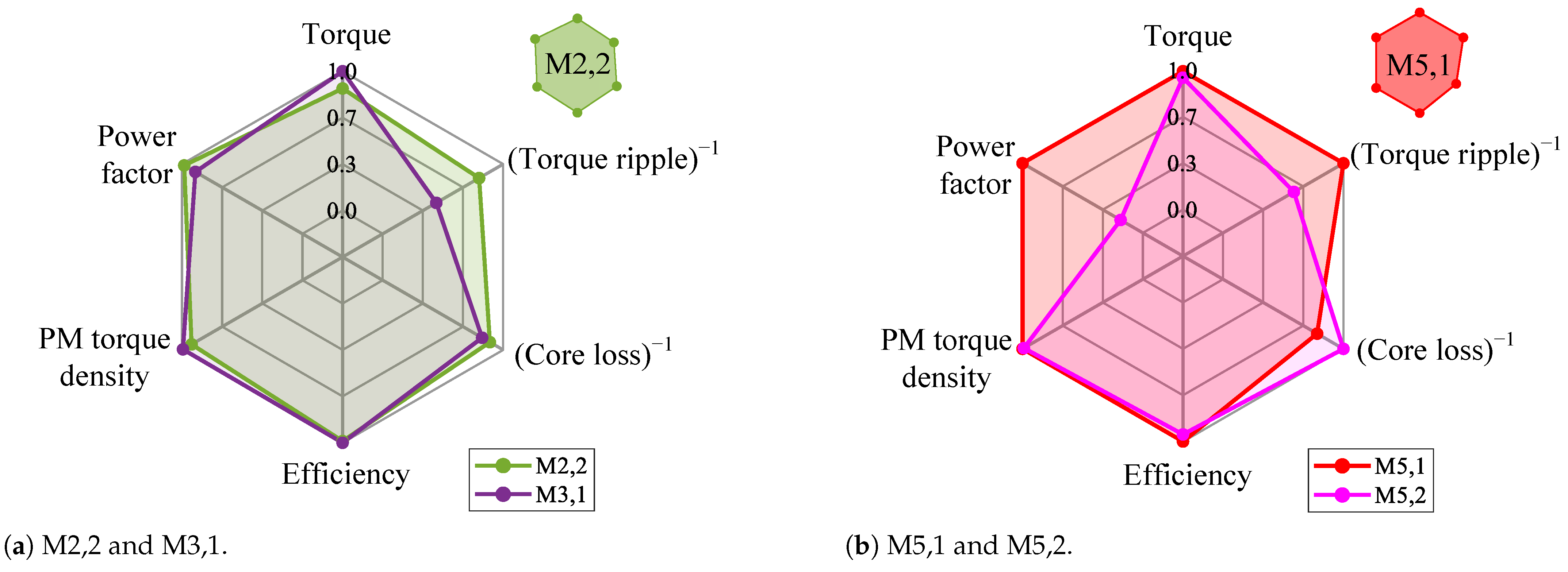
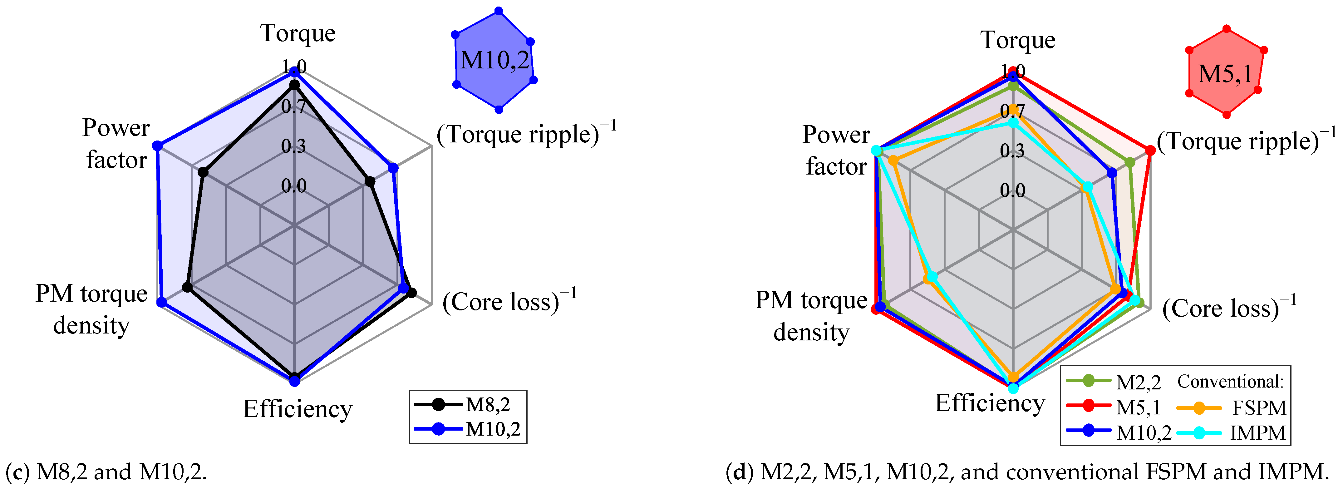
A spider plot based on their area provides a comprehensive and multifaceted comparison of the motors. The six parameters considered in each spider plot are normalised relative to the best performance (
Table 5). Additionally, negative parameters such as ripple and core losses are inverted. Based on these adjustments, the motors are compared pairwise, and, in terms of area, the superior motor (indicated in the upper right) is selected between each pair (
Figure 28). Furthermore, a comprehensive comparison is ultimately conducted among the selected motors. Based on the larger area for each comparison, three selected motors are advanced to the final stage: M2,2, M5,1, and M10,2. In the final comparison, shown in
Figure 28d, the proposed motor M5,1 shows a general improvement in key electromagnetic performances. It is worth noting that the proposed motor M10,2 is also included in the final comparison, demonstrating that the addition of tooth-mounted permanent magnets (PMs) and embedded flux barriers enhances the electromagnetic performance of the conventional E-type structure. Additionally, M5,1 improves the average torque and ripple by 47% and 50%, respectively, compared to its conventional type. Also, M10,2 enhances the average torque and ripple by 68% and 37%, respectively, compared to the conventional IMPM. Additionally, the proposed motors (M5,1 and M10,2) significantly improve the PM torque density by about 115% compared to their conventional type.
5.4. Three-Dimensional FEA Simulations and Lab-Scale Prototype Considerations
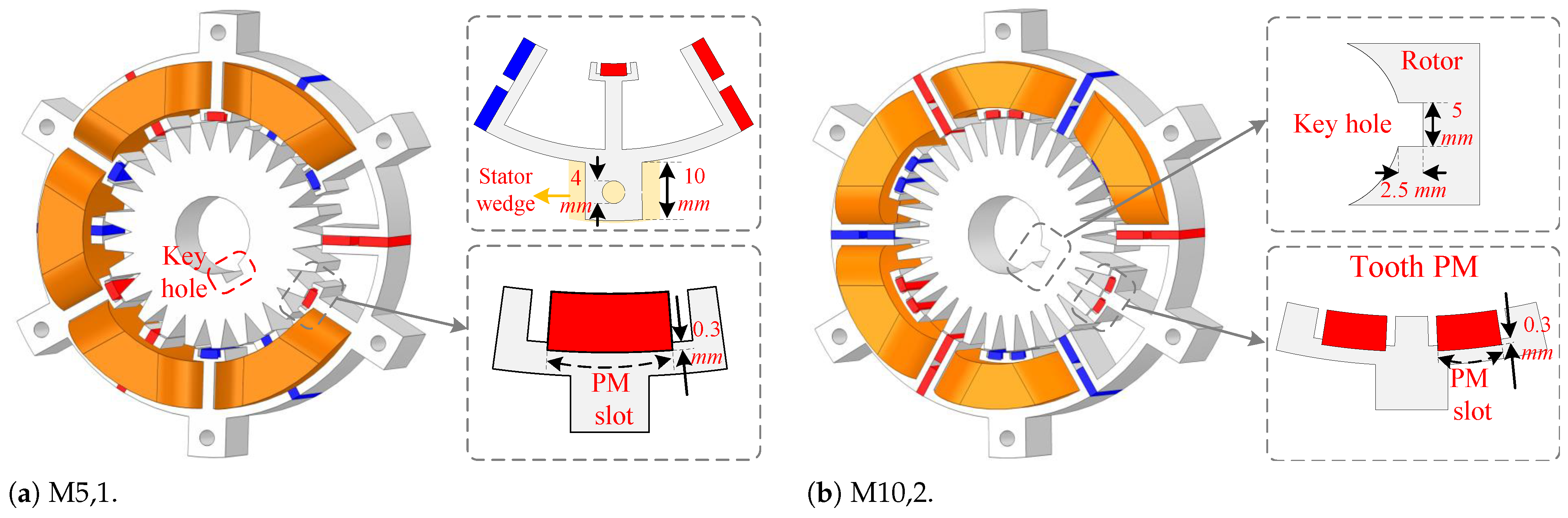
In order to simulate motor performance with values close to real-world conditions, 3D-FEA is conducted for the best motors (M5,1 and M10,2). Additionally, the required components for mounting the motor structure to the frames (such as stator wedges and rotor key holes) are considered to ensure minimal simulation error. The 3D topologies of M5,1 and M10,2 under prototyping conditions are shown in
Figure 29a and
Figure 29b, respectively.
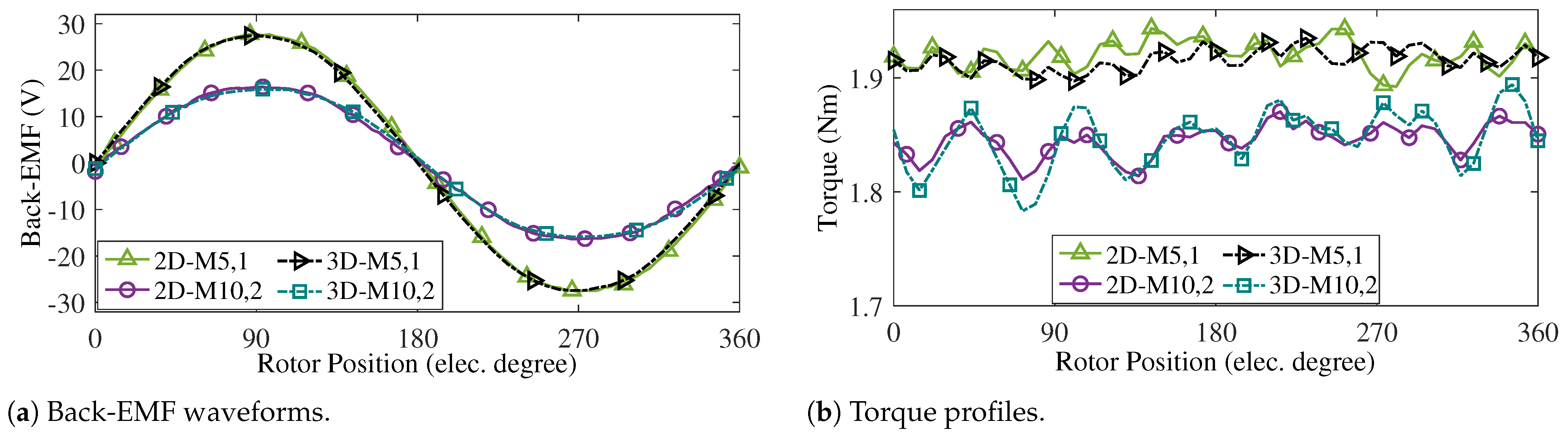
In the following part, the reasons behind the prototyping considerations, such as the inclusion of the tooth PM slot and its dimensions, will be fully discussed to highlight their impact on motor performance and manufacturability. Moreover, the 3D-FEA simulation includes the end-winding effect and utilises over 500,000 mesh elements, which are essential for achieving more accurate and realistic results compared to 2D analyses. These considerations ensure that the simulated outcomes closely reflect the actual behaviour of the motor under real operating conditions. The comparison between the 2D and 3D results for the back-EMF and torque profiles clearly illustrates the differences in accuracy and performance prediction, as shown in
Figure 30a and
Figure 30b, respectively.
The 3D-FEA results of the back-EMF waveforms show less than 1% error compared to the 2D results. Furthermore, the 3D-FEA analysis yields an average torque of 1.91 Nm with a torque ripple of 2.1% for M5,1, and an average torque of 1.85 Nm with a torque ripple of 5.9% for M10,2. The comparison between the 2D- and 3D-FEA results indicates less than 0.5% error in average torque and approximately 5% error in torque ripple.
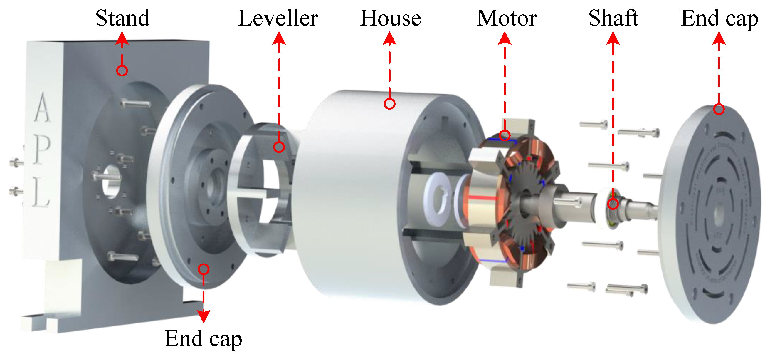
Furthermore, to demonstrate the manufacturability of the proposed motors, the 3D exploded view of one of the structures (M5,1) is presented in
Figure 31. All structures share the same key dimensional parameters, including outer stator radius, shaft radius, air gap length, and stack length. Therefore, the proposed manufacturing process is applicable to the other structures as well. As an example, the prototyping procedure for M5,1 is described in detail.
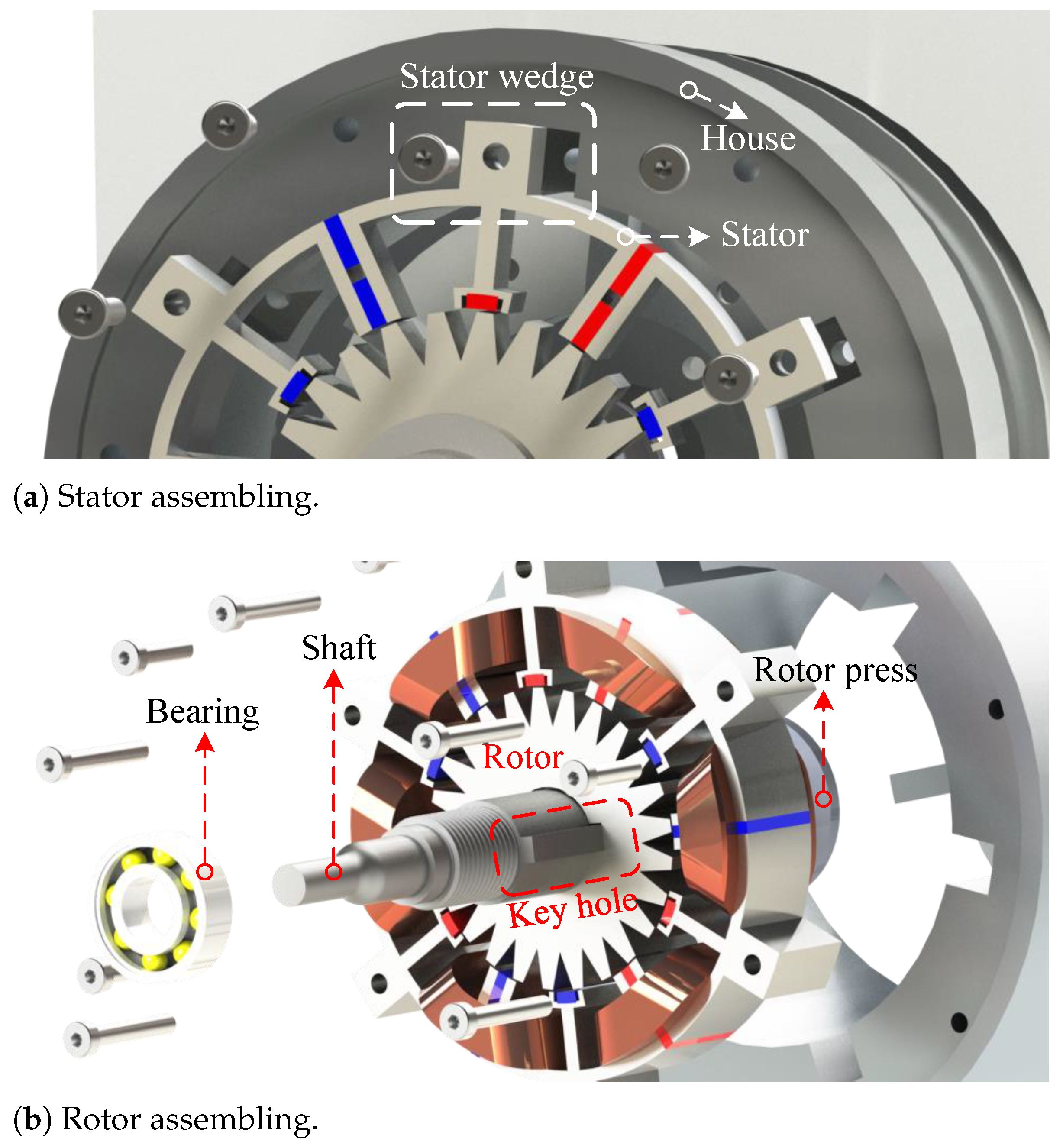
The motor frame consists of two end caps, which are positioned at the front and rear sides of the motor. The rotor is connected to the shaft using a key hole and two rotor press rings, and it is mounted on the end caps via two ball bearings. Additionally, the stator wedges are bolted to the housing. After assembling the end caps and the motor housing together, the motor is mounted on a stand for testing purposes.
The procedure for bolting the stator modules to the housing (frame) using stator wedges is illustrated in
Figure 32a. Additionally, the process of assembling the rotor and mounting it onto the shaft using a key hole is shown in
Figure 32b. Additionally, the dimensions of the stator wedges and key hole are shown in
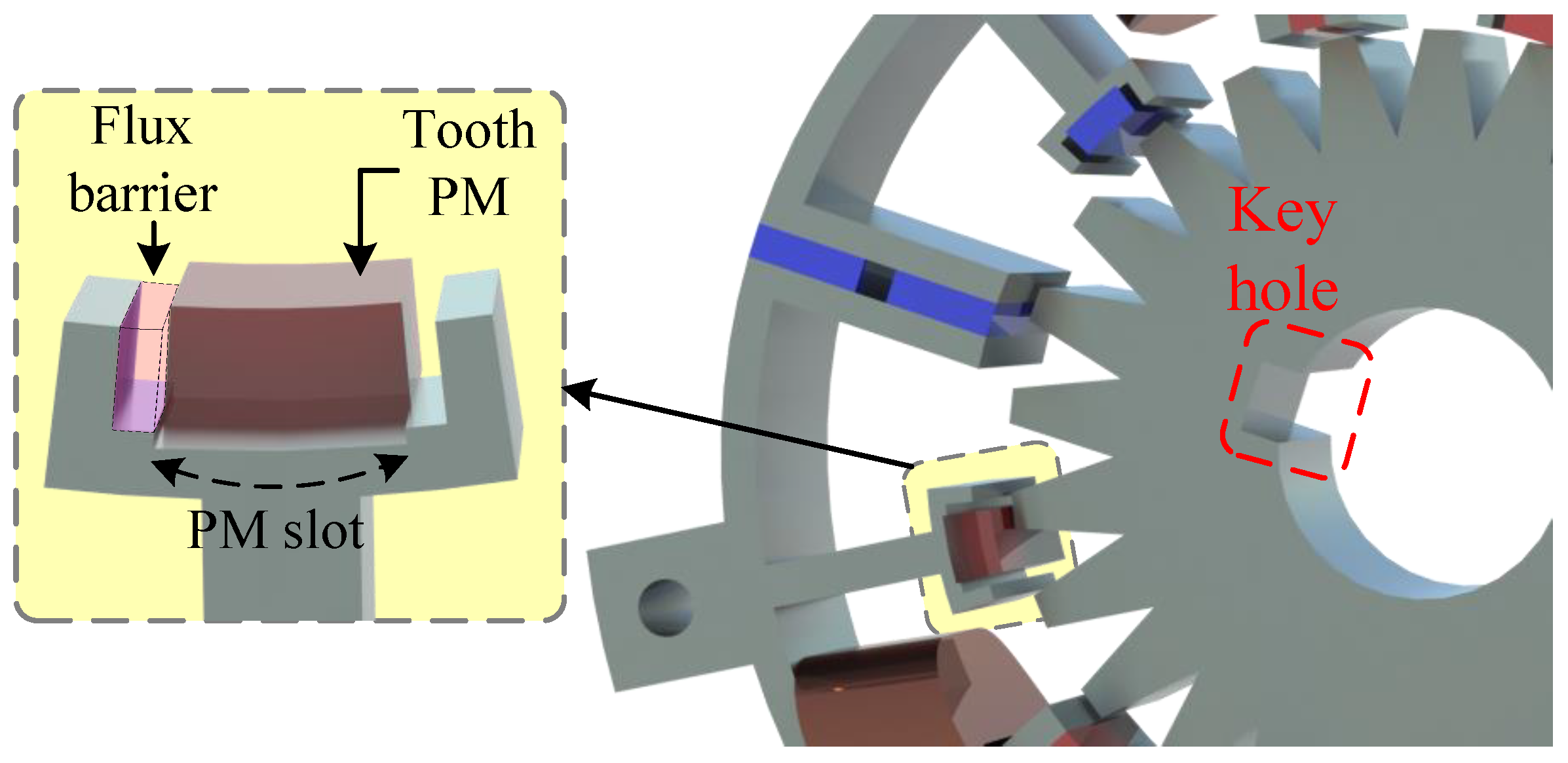
Figure 29. A 0.3 mm deep recess is provided to fix the tooth PMs in the stator. Additionally, instead of leaving air in the flux barrier slots, resin can be used. Resin not only provides better cooling compared to air, but also helps in securing the tooth PMs by surrounding them and holding them firmly in place. Mounting a tooth PM in a 0.3 mm deep PM slot is illustrated in
Figure 33.
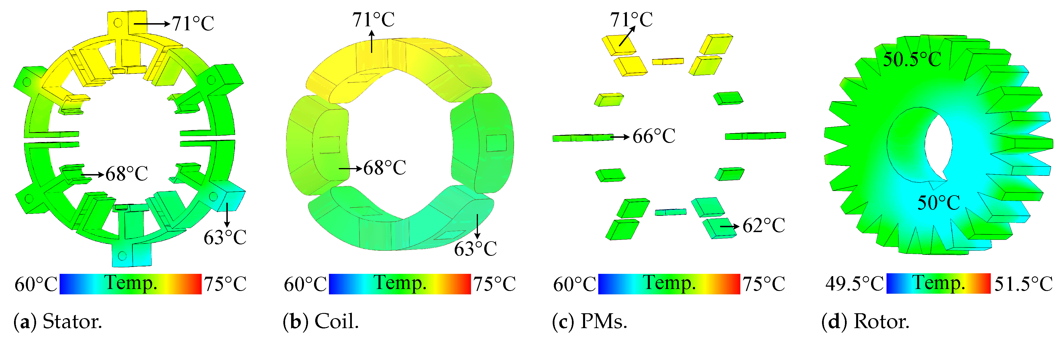
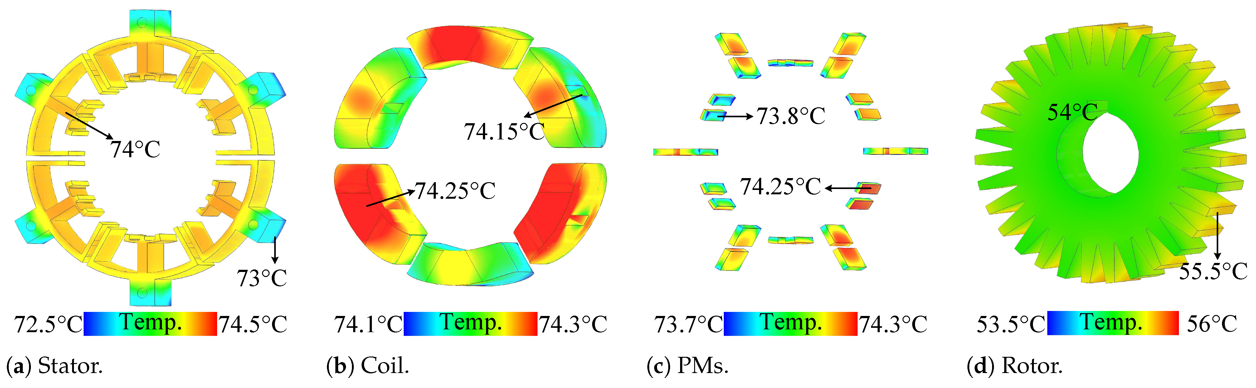
Furthermore, using 3D-FEA, the temperature distribution across different parts of the two best-performing motors, M5,1 and M10,2, is illustrated in
Figure 34 and
Figure 35, respectively.
Under nominal conditions and natural convection cooling, the stator, windings, and PMs of M5,1 remain below 71 °C. In the demagnetisation and thermal analyses, a working temperature of 80 °C is considered to ensure accurate modelling and simulation results (see
Figure 34a,
Figure 34b, and
Figure 34c, respectively). Additionally, the rotor, which is thermally isolated from the main heat sources, maintains a temperature below 51 °C. The thermal analysis of M10,2 also indicates that none of its components exceeds 80 °C. On average, its temperature is only about 4 °C higher than that of M5,1. This temperature distribution confirms that the proposed design methodology does not lead to increased operating temperatures. Furthermore, when compared to conventional FSPM and IMPM structures, studied under the same thermal conditions, current density, and natural convection cooling as reported in [
14], the proposed designs maintain comparable or improved thermal performance. It is also worth noting that, since the current density and other loading conditions remain the same across the designs, with the only difference being the PM arrangement, the temperature variations among the structures are expected to be minimal.
6. Conclusions
This paper presented an innovative design procedure for enhanced E-type stator–PM motors. The methodology encompassed splitting the motor teeth, integrating the advantages of various stator–PM configurations (including the addition of a flux-reversal effect), and embedding flux barriers. The proposed methodology can be extended to other stator–PM motor configurations that utilise either radially or tangentially magnetised PMs. Furthermore, the resulting topologies were optimised using a multi-objective genetic algorithm, with over 36,000 samples analysed. The incorporation of tooth-mounted PMs into the conventional E-type structure achieved a 62% reduction in stator core no-load flux density, significantly lowering the risk of saturation. Moreover, the addition of tooth PMs to conventional E-core modules enhanced torque production by 47% and 68% compared to traditional E-type flux-switching and biased-flux motors, respectively. The subsequent design step, embedding flux barriers, which replaced a portion of the PM material with air, thereby reducing PM volume, led to decreased leakage flux and a more efficient PM arrangement. Additionally, embedding flux barriers mitigated the demagnetisation risk of PMs, a longstanding challenge in stator–PM motors. Finite element analysis results confirmed that this novel stator–PM motor architecture improved key electromagnetic performance metrics, including average torque, torque ripple, core loss, efficiency, PM torque density, and the power factor. The proposed motors enhanced the PM torque density significantly by about 115% compared to conventional motors and reduced the motor costs. Furthermore, the optimisation and decision-making procedures introduced in this research could be applied to other stator–PM motors to derive optimised structures. Thermal analysis for the top-performing motors, M5,1 and M10,2, showed that their temperatures remain below 80 °C. Additionally, 3D-FEA with prototyping considerations resulted in a less than 1% error in average torque compared to the 2D-FEA results, confirming the accuracy and reliability of the simulation approach.


 ,
, 

