Article

A Computationally Efficient Learning-Based Control of a Three-Phase AC/DC Converter for DC Microgrids

Department of Electrical, Electronic and Computer Engineering, University of Western Australia, Perth 6009, Australia
*
Authors to whom correspondence should be addressed.
Energies 2025, 18(9), 2383; https://doi.org/10.3390/en18092383
Submission received: 22 March 2025 / Revised: 27 April 2025 / Accepted: 28 April 2025 / Published: 7 May 2025

Abstract

:
This paper presents a novel learning-based control algorithm for three-phase AC/DC converters, which are key components in DC microgrids, for reliable power conversion. In contrast with conventional model-based nonlinear controllers that rely on detailed system modeling and manual gain tuning, the proposed method is model-free and eliminates such dependencies. By integrating a recurrent equilibrium network (REN), the controller achieves an enhanced dynamic response and robust steady-state performance, while maintaining a low computational complexity. Moreover, its closed-loop stability can be rigorously verified based on contraction theory and incremental quadratic constraints. To facilitate practical implementation, a design guideline is provided. Experimental results confirm that the proposed method outperforms conventional PI and model predictive controllers in terms of response speed, harmonic suppression, and robustness under parameter variations. Additionally, the algorithm is lightweight enough for real-time execution on embedded platforms, such as a TI DSP.

1. Introduction

Three-phase AC/DC converters play an important role in DC microgrids [1,2,3,4]. To obtain excellent AC/DC power conversion performance, several control methods have been devised to simultaneously achieve precise DC-link voltage regulation and maintain unity power factor control.
For instance, the conventional proportional-integral (PI) controller has been employed to regulate the DC-link voltage and currents in the rotating d-q reference frame [5,6,7]. Good steady-state responses have been achieved. However, the fact that it is a linear controller makes it impossible to simultaneously optimize the response speed and overshoot under varying operating conditions. Furthermore, the tuning of PI control gains requires knowledge of the system model. To enhance the performance of AC/DC converters, various sliding mode control (SMC) strategies have been proposed for such converters [8,9,10,11,12,13,14,15,16,17]. For instance, cascaded SMC [9] and predictive SMC [10] are proposed to achieve fast dynamics and good robustness against disturbances. Even though excellent control performances have been reported, these two methods suffer from model parameter dependence, which can lead to a degraded performance under parameter variations. Moreover, they also encounter the chattering issue, generating high-order harmonics in the current. To substantially reduce model dependence and eliminate the chattering issue, a reduced-order generalized proportional-integral observer-based, resonant super-twisting SMC was proposed for a grid-connected AC/DC converter in 2021 [12]. Nevertheless, this approach requires the design and implementation of both the observer and voltage/current controllers, resulting in ahigh design complexity and heavy computational burden. In addition, it is difficult to optimize the observer and controller gains when only the stability-imposed gain constraints are considered.
Over the past decade, model predictive control (MPC) has gained widespread research attention due to its outstanding performance [13]. In [14], finite control set MPC (FCS-MPC) was applied to AC/DC converter control. Compared with SMC, FCS-MPC uses a simple and generic cost function to compute the optimal control actions and thus removes the tedious control gain tuning process. Unfortunately, FCS-MPC suffers from a variable switching frequency and high computational complexity [15]. Furthermore, its performance still depends on the system model. The linear quadratic regulator (LQR) is another feasible optimal control strategy for AC/DC converters [16,17,18,19]. In theory, the traditional LQR finds the optimal duty ratios by solving the algebraic Riccati equation, which requires full knowledge of the system model. To enhance the parameter robustness of the traditional LQR, the authors of [20] employed an observer to recursively estimate the uncertainties and disturbances. Nonetheless, such a design not only increases the computational complexity, but also complicates the observer gain tuning issue.
One possible solution to realize the model-independent, high-performance control of a three-phase AC/DC converter without relying on external observers is to leverage artificial-intelligence (AI)-based control algorithms. For instance, the authors of [21] proposed a robust neural network tracking control strategy using a recurrent radial basis function architecture with online learning to regulate DC bus voltage and manage power sharing in DC microgrids. Although the method demonstrates fast dynamics and low THD, it still relies on a vector control structure and extensive parameter tuning. Moreover, it does not offer an explicit theoretical guarantee of closed-loop stability. Another notable approach was presented in [22], which applies reinforcement learning (RL) integrated with singular perturbation theory to stabilize the DC-side dynamics of grid-connected converters. While this method is model-free and theoretically rigorous, it requires a composite controller design involving fast–slow dynamic decomposition, which increases the design and implementation complexity. Both approaches suggest promising directions, but also reveal that existing AI-based controllers either lack guaranteed stability or face significant computational and implementation burdens.
To address the control challenges mentioned above, this paper proposes an innovative recurrent equilibrium network (REN)-based controller for a three-phase AC/DC converter. The REN network structure enables a low computational complexity. In addition, the nonlinear Youla parameterization technique is used to greatly simplify the neural network training. The main contributions of the proposed algorithm are listed as follows:
  • Superior control performance: Compared with some popular AC/DC converter control methods, such as PI control and MPC, the proposed algorithm provides superior dynamic and steady-state responses;
  • Low computational burden: In comparison with the existing AI-based AC/DC converter controllers, the proposed method significantly reduces the computational burden in both offline neural network training and online implementation;
  • Verifiable closed-loop control stability: Unlike nearly all of the other AI-based converter control algorithms that solely or mainly rely on the offline-trained neural network, the proposed algorithm offers closed-loop control stability that can be explicitly verified.
The remainder of this paper is structured as follows: Section 2 introduces the mathematical model of the three-phase AC/DC converter. Following that, Section 3 elaborates on the proposed REN-based control algorithm and discusses its training and stability verification. Then, the experimental results are shown in Section 4 to validate the effectiveness of the proposed algorithm. Finally, Section 5 concludes the paper.

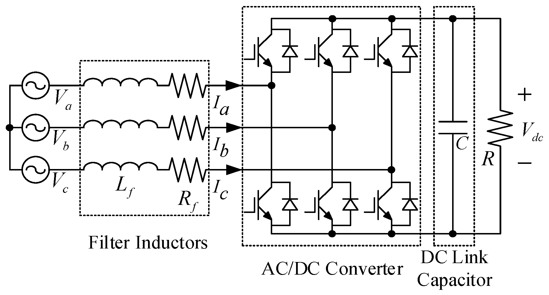
2. Mathematical Model

The topology of a grid-connected three-phase AC/DC converter with a resistive load is shown in Figure 1, where V a , V b , and V c represent the phase voltages, and I a , I b , and I c are the corresponding phase currents. V d c is the voltage of the DC link. L f and R f represent the inductance and parasitic resistance of the inductors, respectively. R is the equivalent load resistance and C denotes the DC-link capacitance.
Its mathematical model in the rotating d-q reference frame is given as follows:
d I d d t = R f L f I d + ω t I q V d c u d 2 L f + V d L f
d I q d t = R f L f I q ω t I d V d c u q 2 L f + V q L f
d V d c d t = 3 I d u d 2 C + 3 I q u q 2 C V d c R C
where I d and I q are the d, q axis currents that are obtained through the Park’s transformation, respectively. u d and u q are the controller outputs and ω t is the grid voltage frequency.

3. The Proposed REN Control Algorithm

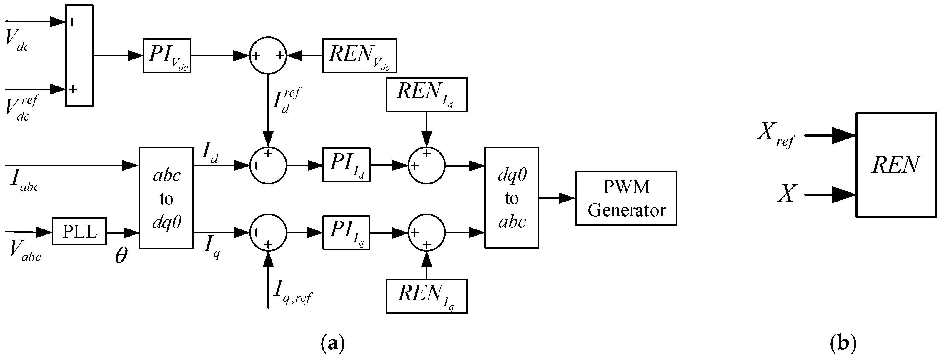
3.1. Base Controller

The block diagram of the proposed controller is shown in Figure 2. In Figure 2a, V a b c and I a b c are three-phase voltages and currents, respectively. V d c r e f , I d r e f , and I q r e f are the reference values of the DC-link voltage, d-axis, and q-axis currents, respectively. P I V d c , P I I d , and P I I q are the PI controllers for the voltage loop, d-axis and q-axis current loops, respectively. R E N V d c , R E N I d , and R E N I q are the proposed REN controllers for the voltage loop, d-axis and q-axis current loops, respectively. In Figure 2b, X r e f denotes the reference value of V d c , I d and I q .
In this paper, the classical PI controller is used as the benchmark controller, which is mathematically expressed as follows:
u P I = K P x r e f x + K I x r e f x d t
where u P I represents the output of the PI controller. In view of unsatisfying dynamic performance of the PI controller, this paper proposes adding a new nonlinear adjustment, which can be expressed as follows:
u = u P I + u R E N
where u R E N n denotes the additional control effort from REN. This adjustment theoretically enables optimal feedback control without model dependence.
The PI controller introduced in this section serves not only as a baseline controller for the proposed REN structure, but also as a reference controller in the subsequent comparative experiments. Its design follows a conventional two-loop control structure with an inner current loop and an outer voltage loop, as adopted in [5]. The PI controller parameters are tuned accordingly and listed in Table 1. It is worth emphasizing that the same set of PI parameters is consistently used both in the baseline design for REN and in the experimental comparisons. This ensures a fair evaluation and highlights the performance enhancement achieved by the REN-based optimization.

3.2. Configuration of REN

The proposed REN can be represented using a state-space model as follows:
x t + 1 = A x t + B 1 w t + B 2 u t + b x y t = C 2 + D 21 w t + D 22 u t + b y
Here, w t can be regarded as a solution to an equilibrium network, a.k.a., an implicit network [23]:
w t = σ ( C 1 x t + D 11 w t + D 12 u t + b v )
where A , B 1 , B 2 , C 1 , C 2 , D 11 , D 12 , D 21 , and D 22 denote the approximation matrices, and b x , b y , and b v denote the bias vectors. σ is the rectified linear unit (ReLU), which is a nonlinear activation function. It can be expressed as follows:
σ ( x ) = max ( x , 0 )
The term “equilibrium” in REN can be explained as follows: any solution to the above implicit Equation (7) is also an equilibrium point for the ordinary differential equation
d w t ( s ) d s = w t ( s ) + σ ( D w t ( s ) + b w )
with
b w = C 1 x t + D 12 u t + b v
where x t is the value of the sequence x at time t . b w is considered “frozen” for each t . In essence, REN is a dual time scale perturbation model, which contains fast dynamics characterized by w t and slow dynamics captured by x t . The interactions between fast and slow dynamics are described by the following:
Δ x t + 1 Δ v t Δ y t = A B 1 B 2 C 1 D 11 D 12 C 2 D 21 D 22 Δ x t Δ w t Δ v t
where
Δ w t = σ ( v t + Δ v t ) σ ( v t )
In theory, ReLU constrains its input signal’s slope to be within [ 0 , 1 ] , i.e.,
0 σ ( a ) σ ( b ) a b 1
Thus, σ satisfies the incremental integral quadratic constraints:
Γ ( Δ v t , Δ w t ) = Δ v t Δ w t 0 Λ Λ 2 Λ 0
where Λ is a positive diagonal matrix.
Definition 1.
The system is considered to be contracting at a rate of α ( α 0 , 1 ) [24], if for any two initial conditions  a , b n , input sequence u , and state sequence x a and x b , the condition in (15) is satisfied.
x t a x t b K α t a b
Roughly speaking, a contracting system exponentially forgets its initial conditions. Further, the following form of robustness constraint is defined:
Definition 2.
For a system in (6), if all its solutions with initial conditions a , b and input sequences u , v , the output sequences y a , y b can satisfy
t = 0 T y t a y t b u t v t T Q S T S R y t a y t b u t v t d a , b
for some functions d a , b 0 with d a , a = 0 . This system is said to satisfy the incremental integral quadratic constraint.
Lemma 1.
REN contracts at rate of α α ¯ ( α ¯ ( 0 , 1 ] ), if there exists P = P T 0 (Note that A 0 denotes a positive definite matrix) satisfying:
α ¯ 2 P C 1 T Λ Λ C 1 2 Λ Λ D 11 D 11 T Λ A T B 1 T P A T B 1 T T 0
α ¯ 2 P C 1 T Λ C 2 T S T Λ C 1 2 Λ Λ D 11 D 11 T Λ D 21 T S T Λ D 12 S C 2 S D 21 D 12 T Λ R + S D 22 + D 22 T S T A T B 1 T B 2 T P A T B 1 T B 2 T T + C 2 T D 21 T D 22 T Q C 2 T D 21 T D 22 T T 0
Proof. 
Multiplying (17) on the left side by Δ x t T Δ w t T and on the right side and by Δ x t T Δ w t T T , the incremental Lyapunov inequality is obtained as follows:
Δ x t + 1 P 2 α 2 Δ x t P 2 Γ ( Δ v t , Δ w t ) α 2 Δ x t P 2
Iterating over t provides (15) with:
K = σ ^ σ ˜
where σ ^ and σ ˜ are the maximum and minimum singular values of P , respectively. Similarly, multiplying inequality (18) on the left side by Δ x t T Δ w t T Δ u t T and on the right side by Δ x t T Δ w t T Δ u t T T , the incremental Lyapunov inequality is obtained as follows:
Δ x t + 1 P 2 α 2 Δ x t P 2 Γ ( Δ v t , Δ w t ) + Δ y t Δ u t T Q S T S R Δ y t Δ u t
Telescoping sum of (21) yields (16) with:
d ( a , b ) = ( b a ) T P ( b a )
Moreover, considering Q 0 and Δ u t = 0 , (21) can be transformed to (19), which completes the proof. □

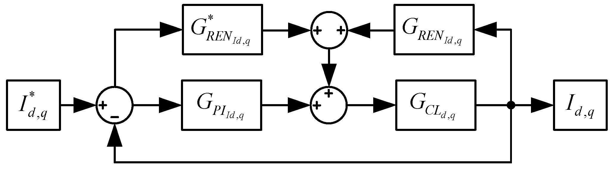
3.3. Stability Analysis of Current Loop

The block diagram of the current control loop is shown in Figure 3, where I d , q represents the reference d-q axis currents; I d , q denotes of the actual d, q-axis currents. G P I I d , q is the transfer function of current PI controllers, whose expression is given in [5]:
G P I I d , q = 1 + τ C L s τ C L s
where τ C L is the time constant, which can be calculated as follows:
τ C L = K P , C L K I , C L
where K P , C L and K I , C L are the proportional and integral gains of the current PI controller, respectively. Note that the current controller is designed to obtain a 5% overshoot in response to the step current change [5].
G C L d , q is the converter model in d, q-axis, which can be mathematically expressed as follows:
G C L d , q = 1 R f L f R f s + 1
G R E N I d , q and G R E N I d , q are transfer functions of REN in response to input I d , q and output I d , q , respectively. The transfer function of the current loop can be expressed as follows:
G C L ( s ) = G C L d , q ( G P I I d , q + G R E N I d , q ) 1 + G C L d , q ( G P I I d , q G R E N I d , q )
Physically, the variations in filter inductance L f in the AC/DC converter are generally within ± 30 % of its nominal value and the changes in its parasitic resistance R f have a negligible impact on the converter responses. Under such circumstances, according to the linear parameter-varying (LPV) theory, all the eigenvalues of THE characteristic equation 1 + G C L d , q ( G P I I d , q G R E N I d , q ) = 0 are found to have negative real parts for any inductance in the range [ 0.7 L , 1.3 L ] , which proves the stability of the current control loop.

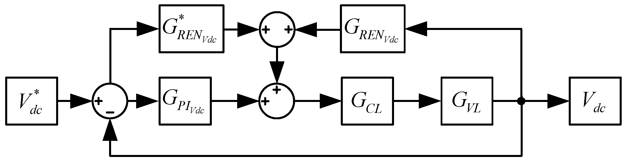
3.4. Stability Analysis of Voltage Loop

The block diagram of the voltage control loop is shown in Figure 4, where V d c and V d c denote the reference and actual DC-link voltage, respectively.
G P I V d c is the transfer function of the PI controller for the voltage loop, which can be expressed as follows [5]:
G P I V d c = 1 + τ V L s τ V L s
where τ V L is the time constant, which can be calculated as follows:
τ V L = K P , V L K I , V L
where K P , V L and K I , V L are proportional and integral gains of the voltage PI controller, respectively. Note that the voltage controller is designed to have a 5% overshoot in response to the step DC-link voltage changes [5].
G V L is the plant of the voltage control loop, which can be expressed as follows [5]:
G V L = 3 2 L I s o s + V s o C V d c o s + 2 V d c o R
where V s o , V d c o , and I s o are the amplitudes of the input AC voltage, output DC voltage, and line current around the operating point, respectively.
G R E N V d c and G R E N V d c are the transfer functions of REN in response to input V d c and output V d c . The transfer function of the voltage loop can be expressed as follows:
G ( s ) = G V L G C L ( G P I V d c + G R E N V d c ) 1 + G V L G C L ( G P I V d c G R E N V d c )
Similar to the situation of inductance variation, the variation of DC-link capacitance is generally confined to be within ± 10 % of its nominal value throughout its lifetime. All the eigenvalues of characteristic equation 1 + G V L G C L ( G P I V d c G R E N V d c ) = 0 are found to have negative real parts for any inductance in the range 0.9 C , 1.1 C , which proves the stability of the voltage control loop.

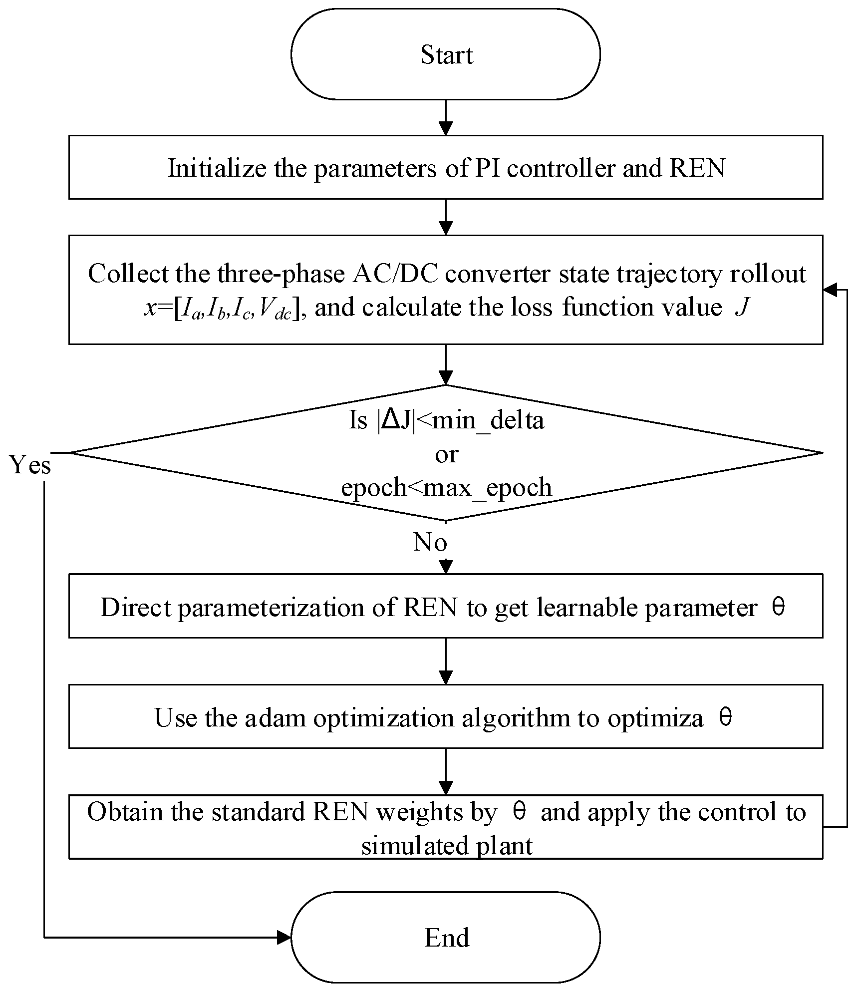
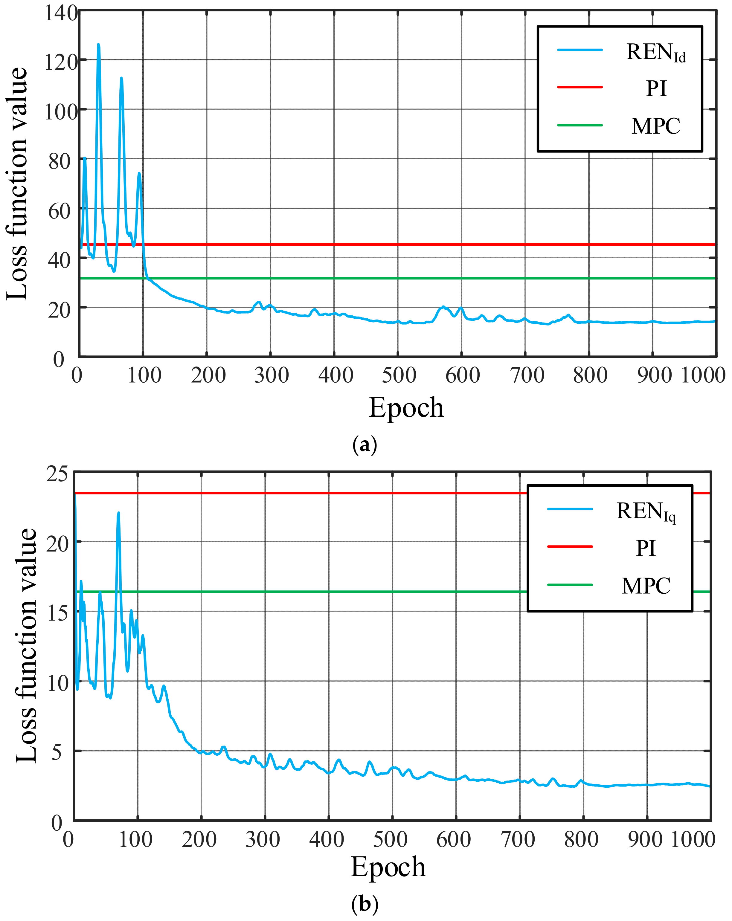
3.5. Policy Training Details

In this study, REN is parameterized and trained using the Julia programming language and Adam optimizer. The flowchart of the training process is depicted in Figure 5. Each of the three previously mentioned RENs consisted of 6 neurons and 3 states. The Julia Zygote toolkit is utilized for computing the loss function J = k = 1 ( V d c , r e f V d c ) 2 and its gradients Δ J . Then, the Adam optimizer is employed for updating the parameter vector θ . The loss functions for the d, q-axis currents and DC-side voltage during training are illustrated in Figure 6. It can be observed from Figure 6a–c that the proposed controller can converge to a loss value significantly lower than that of the classical PI controllers and MPC controllers.
It should be noted that in Figure 6, the PI and MPC controllers are conventional baseline methods and are not subject to optimization. Therefore, their loss values remain unchanged throughout the training process. In contrast, the REN controller is iteratively optimized to minimize the cost function.

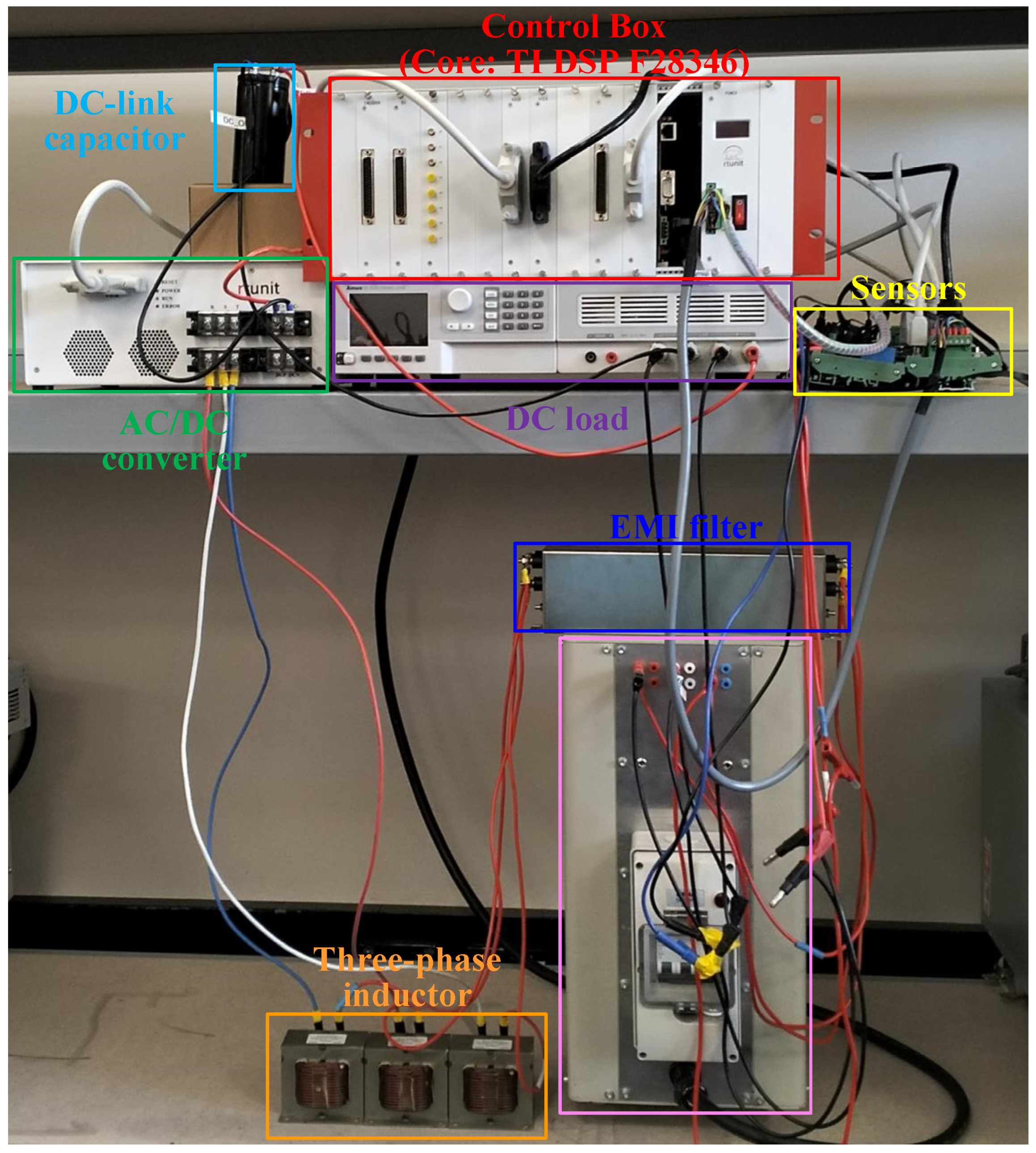
4. Experiment Results

To verify the effectiveness of the proposed REN-based control algorithm, experiments were carried out on a three-phase AC/DC converter setup, as illustrated in Figure 7. This setup included a grid-connected transformer, EMI filter, three-phase inductors, AC/DC converter, sensor board, DC load, Texas Instruments (TI) digital signal processor (DSP) TMSF28346, sourced from Texas Instruments (TI), Dallas, TX, USA, and an oscilloscope. The parameters of this experimental setup are provided in Table 2.

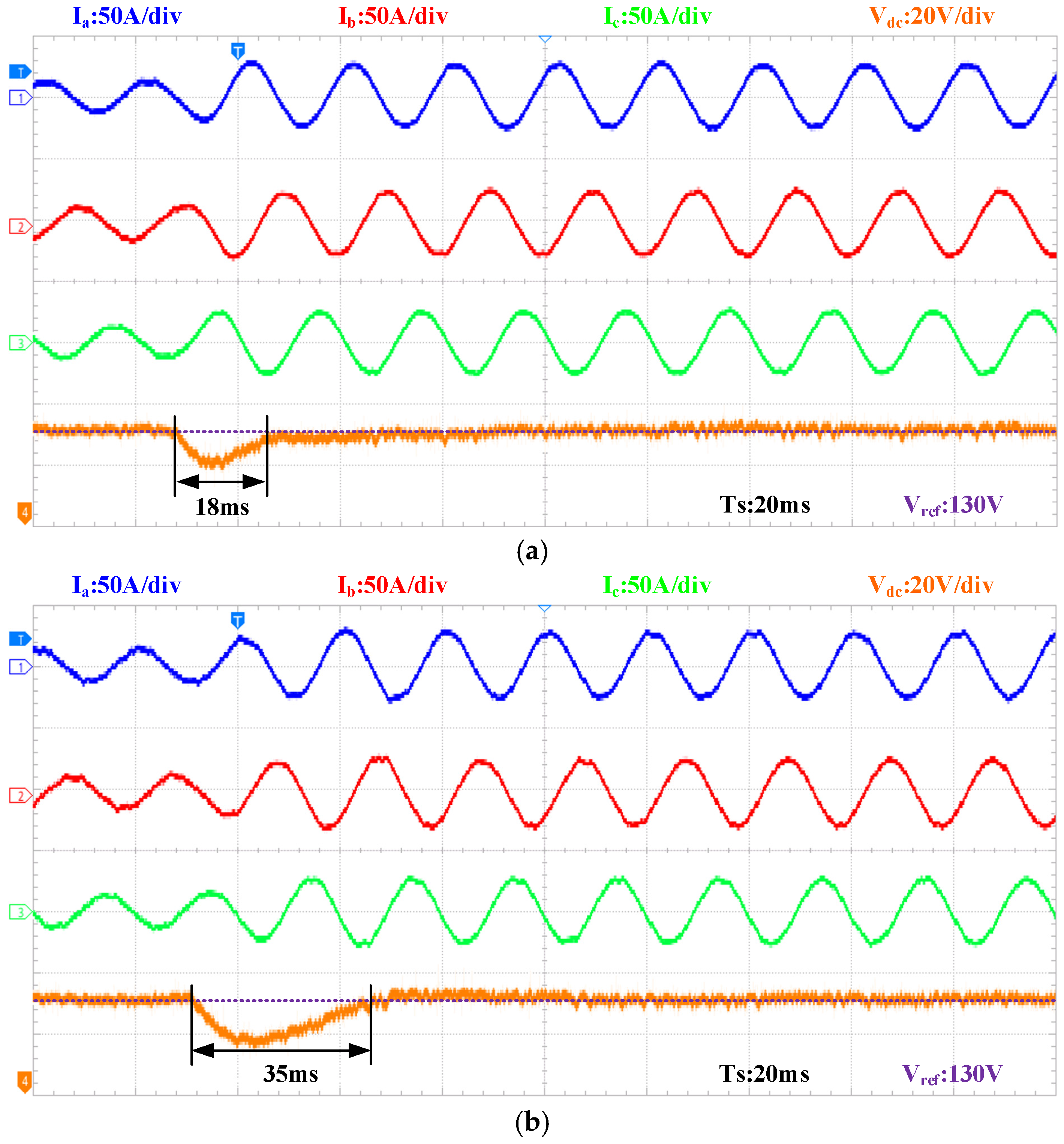
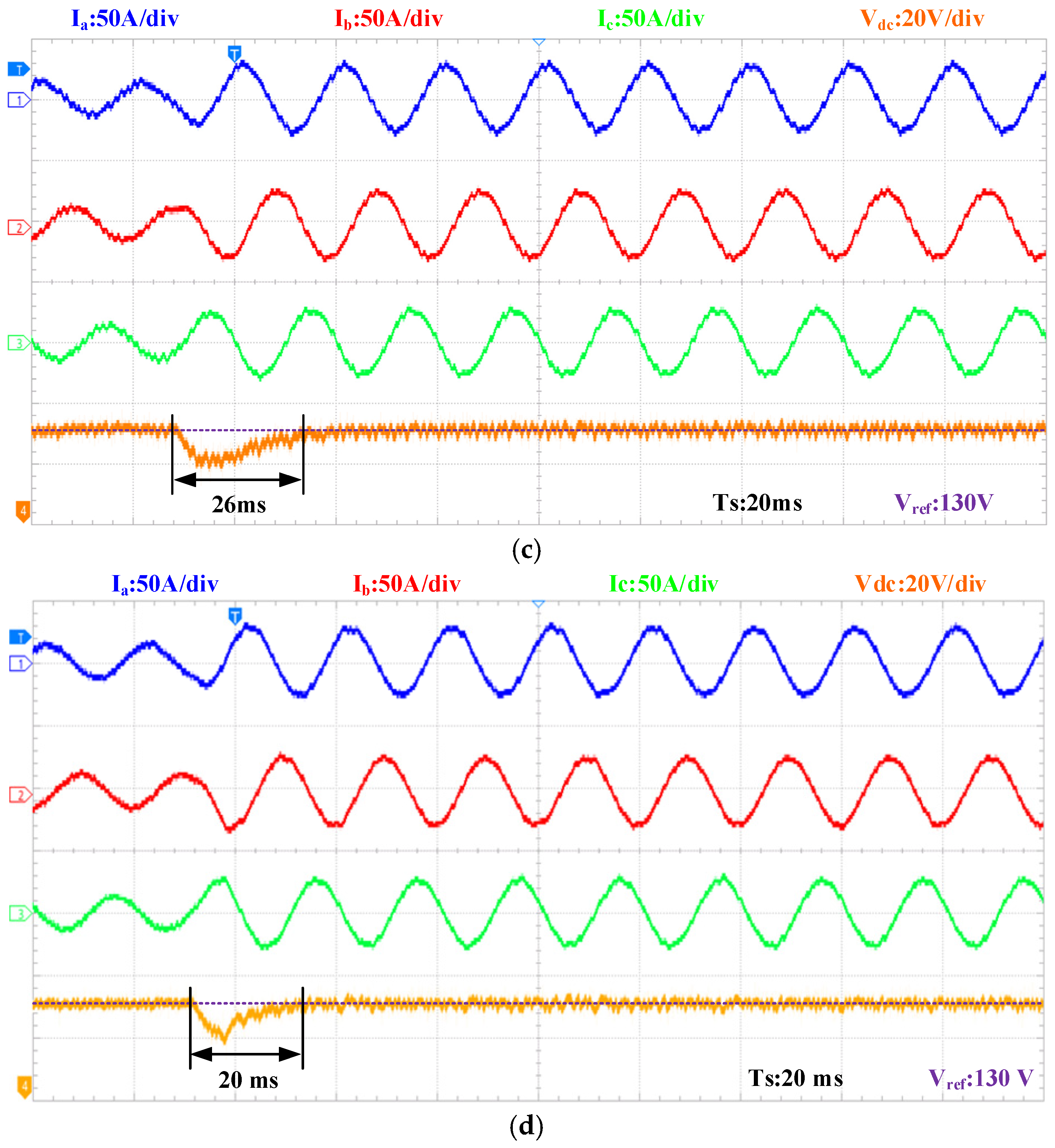
4.1. Transient Performance Under Step Load Charge

The transient performance of the proposed REN-based controller is compared with the traditional PI controller, linear quadratic regulator (LQR), and MPC. The results of a sudden load increase are depicted in Figure 8, in which the load resistance drops from 20 Ω to 10 Ω. From Figure 8a, it can be observed that the proposed algorithm restores the DC-link voltage back to the reference value of 130 V in approximately 18 ms. In comparison, the settling time for the PI controller, MPC, and LQR are about 35 ms, 26 ms, and 20 ms, as shown in Figure 8b, Figure 8c, and Figure 8d, respectively. Thus, the proposed algorithm demonstrates a significantly improved transient response.

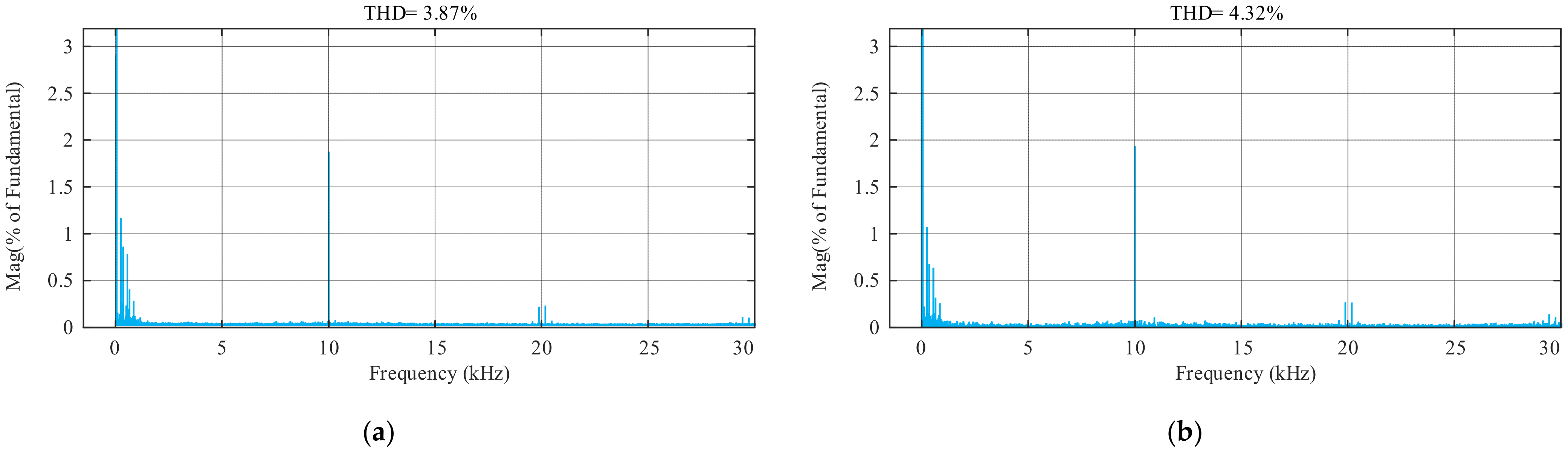
4.2. Steady-State Performance with Nominal System Parameters

When the load is 10 Ω, the total harmonic distortion (THD) of the steady-state current waveforms obtained by the three previously mentioned control methods is shown in Figure 9. With the same sampling frequency, the proposed algorithm produces a THD of 3.87%, as shown in Figure 9a, whereas the THDs of the PI controller, the MPC and the LQR are 4.32%, 19.39%, and 3.72%, as illustrated in Figure 9b–d. This result highlights the superior steady-state performance of the proposed algorithm.

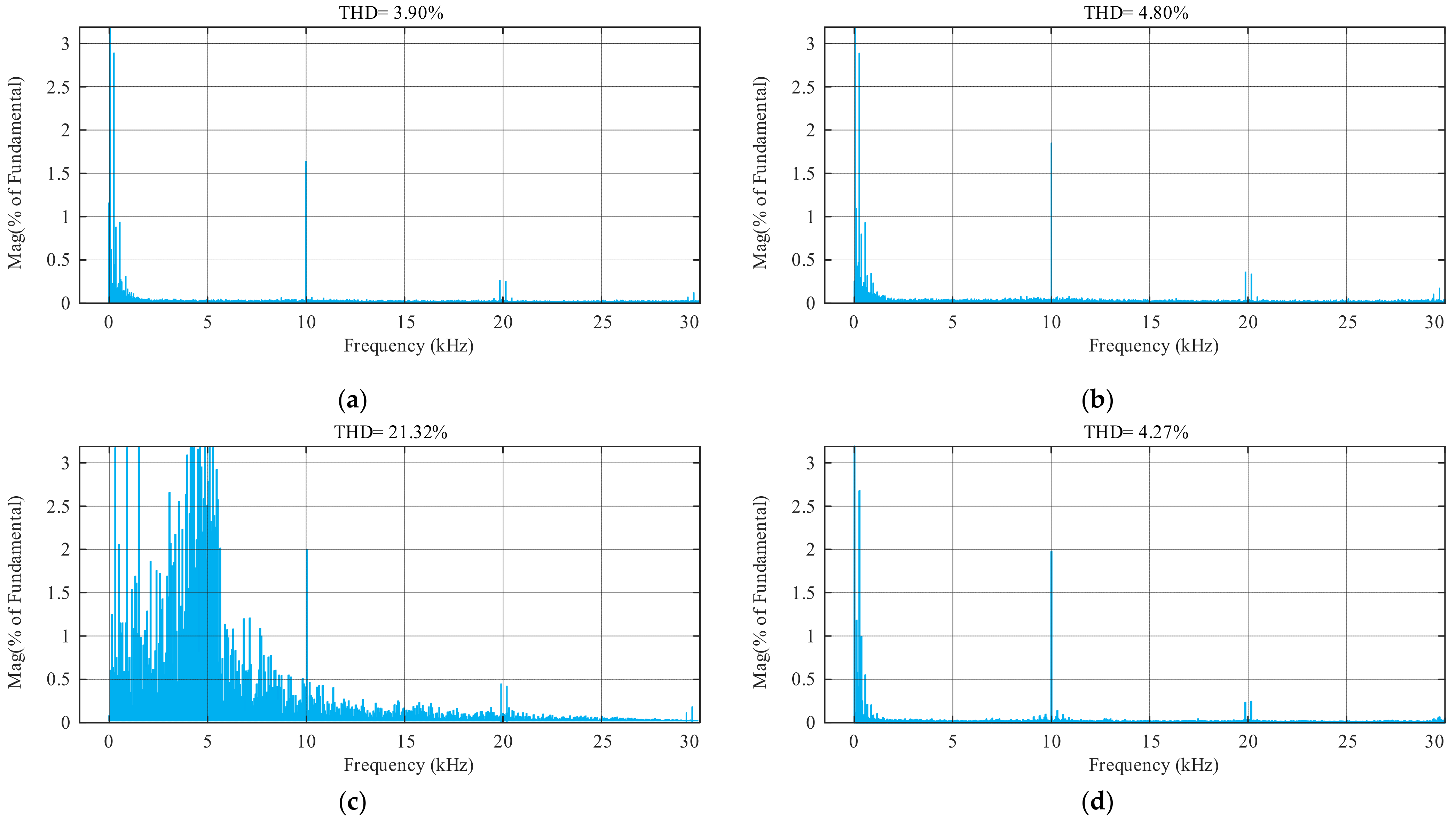
4.3. Control Performance Under Detuned Model Parameter

To illustrate the model independence of the proposed algorithm, these three control methods were further tested with the detuned filter inductance detuned to 70% of its nominal value. Figure 10 shows the THD of the steady-state current waveform when the load was set to 10 Ω. As shown in Figure 10a, the THD of the proposed algorithm was 3.90%, representing a less than 1% increase compared with the situation without parameter variation. Therefore, it can be concluded that the proposed method is insensitive to parameter variations. In comparison, the THDs of the PI controller, MPC, and LQR, as shown in Figure 10b, Figure 10c, and Figure 10d, were 4.9%, 21.32%, and 4.27%, respectively. Such results indicate that THD increased by approximately 13.4%, 9.9%, and 14.8% for the PI controller, MPC, and LQR, respectively.

4.4. Computational Efficiency

To assess the online computational complexity of the proposed REN controller, its execution time on the TI DSP F28346 was measured. The result was approximately 25.8 μs, demonstrating the low computational burden of the proposed method.

5. Conclusions

This paper presents an innovative, model-independent learning-based control algorithm for the three-phase AC/DC converter in DC microgrids. Compared with the baseline controller, the REN-optimized controller improves transient response speed by 48.6% and reduces steady-state THD by 10.42%, while maintaining an excellent performance under reasonable variations in system parameters. In addition, the proposed method offers superior control quality with a low computational burden in both offline neural network training and online implementation, making it highly suitable for real-time industrial applications on microprocessors. Most importantly, its closed-loop control stability can be explicitly verified.

Author Contributions

Methodology, R.L., W.F. and Y.L.; Software, R.L. and W.F.; Validation, R.L. and T.Q.; Writing—original draft, R.L., X.Z., H.H.I. and T.F.; Writing—review & editing, X.Z.; Visualization, R.L.; Supervision, T.F., H.H.I. and X.Z. All authors have read and agreed to the published version of the manuscript.

Funding

This work is funded by Australian Future Battery Industries Corporate Research Center “Mine Electrification” project (grant number BU/PG: 00660/55005100). The article processing charge (APC) was waived by the publisher as this manuscript was invited and published free of charge.

Data Availability Statement

No new data were created or analyzed in this study. Data sharing is not applicable to this article.

Conflicts of Interest

The authors declare no conflict of interest.

References

  1. Wu, H.; Wang, J.; Liu, T.; Yang, T.; Xing, Y. Modified SVPWM-Controlled Three-Port Three-Phase AC–DC Converters with Reduced Power Conversion Stages for Wide Voltage Range Applications. IEEE Trans. Power Electron. 2018, 33, 6672–6686. [Google Scholar] [CrossRef]
  2. Fu, C.; Zhang, C.; Zhang, G.; Song, J.; Zhang, C.; Duan, B. Disturbance Observer-Based Finite-Time Control for Three-Phase AC–DC Converter. IEEE Trans. Ind. Electron. 2022, 69, 5637–5647. [Google Scholar] [CrossRef]
  3. Tomida, K.; Natori, K.; Xu, J.; Shimosato, N.; Sato, Y. A New Control Method to Realize Wide Output Voltage Range for Three Phase AC/DC Converter Based on Matrix Converter. In Proceedings of the 2022 International Power Electronics Conference (IPEC-Himeji 2022-ECCE Asia), Himeji, Japan, 15–19 May 2022. [Google Scholar]
  4. Ran, X.; Xu, B.; Liu, K.; Liu, Y. A Three-Vector Finite Control Set Model Predictive Control Variant with Low Power Fluctuations of AC/DC Converters. IEEE J. Emerg. Sel. Top. Ind. Electron. 2024, 5, 1338–1343. [Google Scholar] [CrossRef]
  5. Zargari, N.R.; Joos, G. Performance investigation of a current-controlled voltage-regulated PWM rectifier in rotating and stationary frames. IEEE Trans. Ind. Electron. 1995, 42, 396–401. [Google Scholar] [CrossRef]
  6. Blasko, V.; Kaura, V. A new mathematical model and control of a three-phase AC-DC voltage source converter. IEEE Trans. Power Electron. 1997, 12, 116–123. [Google Scholar] [CrossRef]
  7. Verdelho, P.; Marques, G.D. DC voltage control and stability analysis of PWM-voltage-type reversible rectifiers. IEEE Trans. Ind. Electron. 1998, 45, 263–273. [Google Scholar] [CrossRef]
  8. Shtessel, Y.; Baev, S.; Biglari, H. Unity Power Factor Control in Three-Phase AC/DC Boost Converter Using Sliding Modes. IEEE Trans. Ind. Electron. 2008, 55, 3874–3882. [Google Scholar] [CrossRef]
  9. Zhang, X.N.; Vilathgamuwa, D.M.; Foo, G.; Tseng, K.J.; Kandasamy, K.; Gupta, A.K.; Chandana, G. Cascaded sliding mode control for global stability of three phase AC/DC PWM rectifier with rapidly varying power electronic loads. In Proceedings of the IECON 2013—39th Annual Conference of the IEEE Industrial Electronics Society, Vienna, Austria, 10–13 November 2013. [Google Scholar]
  10. He, T.; Lu, D.D.-C.; Li, L.; Zhang, J.; Zheng, L.; Zhu, J. Model-Predictive Sliding-Mode Control for Three-Phase AC/DC Converters. IEEE Trans. Power Electron. 2018, 33, 8982–8993. [Google Scholar] [CrossRef]
  11. Jeeranantasin, N.; Nungam, S. Sliding Mode Control of Three-Phase AC/DC Converters using Exponential Rate Reaching Law. J. Syst. Eng. Electron. 2022, 33, 210–221. [Google Scholar] [CrossRef]
  12. Lu, J.; Savaghebi, M.; Ghias, A.M.Y.M.; Hou, X.; Guerrero, J.M. A Reduced-Order Generalized Proportional Integral Observer-Based Resonant Super-Twisting Sliding Mode Control for Grid-Connected Power Converters. IEEE Trans. Ind. Electron. 2021, 68, 5897–5908. [Google Scholar] [CrossRef]
  13. Kim, S.-K.; Choi, D.-K.; Lee, K.-B.; Lee, Y.I. Offset-Free Model Predictive Control for the Power Control of Three-Phase AC/DC Converters. IEEE Trans. Ind. Electron. 2015, 62, 7114–7126. [Google Scholar] [CrossRef]
  14. Falkowski, P.; Sikorski, A. Finite Control Set Model Predictive Control for Grid-Connected AC–DC Converters with LCL Filter. IEEE Trans. Ind. Electron. 2018, 65, 2844–2852. [Google Scholar] [CrossRef]
  15. Zhang, Y.; Zhang, Q. Relationship between finite control set model predictive control and direct current control for three-phase voltage source converters. In Proceedings of the 2014 International Power Electronics and Application Conference and Exposition, Shanghai, China, 5–8 November 2014. [Google Scholar]
  16. Zerouali, S.; Allag, A.; Mimoune, S.M.; Ayad, M.Y.; Becherif, M.; Miraoui, A.; Khanniche, S. An Adaptive Optimal Linear Quadratic Regulator Applied to Three Phases PWM AC-DC Converter. In Proceedings of the IECON 2006-32nd Annual Conference on IEEE Industrial Electronics, Paris, France, 7–10 November 2006. [Google Scholar]
  17. Kedjar, B.; Al-Haddad, K. DSP-Based Implementation of an LQR With Integral Action for a Three-Phase Three-Wire Shunt Active Power Filter. IEEE Trans. Ind. Electron. 2009, 56, 2821–2828. [Google Scholar] [CrossRef]
  18. Patarroyo-Montenegro, J.F.; Andrade, F.; Guerrero, J.M.; Vasquez, J.C. A Linear Quadratic Regulator with Optimal Reference Tracking for Three-Phase Inverter-Based Islanded Microgrids. IEEE Trans. Power Electron. 2021, 36, 7112–7122. [Google Scholar] [CrossRef]
  19. Rakhshani, E.; Cantarellas, A.M.; Remon, D.; Rodriguez, P.; Candela, I. Modeling and control of multi modular converters using optimal LQR controller with integral action. In Proceedings of the 2013 IEEE Energy Conversion Congress and Exposition, Denver, CO, USA, 15–19 September 2013. [Google Scholar]
  20. Kanieski, J.M.; Cardoso, R.; Pinheiro, H.; Gründling, H.A. Kalman Filter-Based Control System for Power Quality Conditioning Devices. IEEE Trans. Ind. Electron. 2013, 60, 5214–5227. [Google Scholar] [CrossRef]
  21. Soliman, S.; Rafin, S.M.S.H.; Mohammad, O.A. Enhanced DC Voltage and Power Regulation Using Intelligent Data-Driven Control for AC/DC Converters in DC Microgrid Applications. IEEE Trans. Ind. Appl. 2024, 60, 8383–8392. [Google Scholar] [CrossRef]
  22. Davari, M.; Zhao, J.; Yang, C.; Gao, W.; Chai, T. Reinforcement Learning to Stabilize Singularly Perturbed DC-Side Dynamics of Grid-Connected Voltage-Source Converters in Modern AC–DC Grids Using Singular Perturbation Theory and Adaptive Dynamic Programming. IEEE Trans. Ind. Electron. 2025, 72, 2914–2926. [Google Scholar] [CrossRef]
  23. El Ghaoui, L.; Gu, F.; Travacca, B.; Askari, A.; Tsai, A. Implicit deep learning. SIAM J. Math. Data Sci. 2021, 3, 930–958. [Google Scholar] [CrossRef]
  24. Lohmiller, W.; Slotine, J.-J.E. On contraction analysis for non-linear systems. Automatica 1998, 34, 683–696. [Google Scholar] [CrossRef]
Figure 1. Topology of the three-phase AC/DC converter.
Energies 18 02383 g001
Figure 2. Block diagram of the proposed controller: (a) control loop, (b) inputs of REN.
Energies 18 02383 g002
Figure 3. The block diagram of the current loop.
Energies 18 02383 g003
Figure 4. The block diagram of the voltage loop.
Energies 18 02383 g004
Figure 5. REN training flowchart.
Energies 18 02383 g005
Figure 6. Loss function values in the training process: (a) Loss function value of REN for d-axis current control, (b) loss function value of REN for q-axis current control, and (c) loss function value of REN for DC-link voltage control.
Energies 18 02383 g006aEnergies 18 02383 g006b
Figure 7. Experimental setup of the three-phase AC/DC converter system.
Energies 18 02383 g007
Figure 8. Experimental results of the AC/DC converter with a step load resistance decrease from 20 Ω to 10 Ω: (1) channel 1: current Ia (blue) 50 A/div, (2) channel 2: current Ib (red) 50 A/div, (3) channel 3: current Ic (green) 50 A/div, (4) channel 4: DC-link voltage (orange) 20 V/div, (a) voltage tracking response of REN, (b) voltage tracking response of PI, and (c) voltage tracking response of MPC, (d) voltage tracking response of LQR.
Energies 18 02383 g008aEnergies 18 02383 g008b
Figure 9. THD analysis of phase current under REN, PI, and MPC with a load of 10 Ω: (a) THD of phase-a current obtained by the proposed REN-based controller, (b) THD of phase-a current obtained by the PI controller, (c) THD of phase-a current obtained by MPC, and (d) THD of phase-a current obtained by LQR.
Energies 18 02383 g009aEnergies 18 02383 g009b
Figure 10. THD analysis of phase current of REN, PI, and MPC with a load of 10Ω under detuned model parameters: (a) THD of phase-a current obtained by the proposed REN-based controller, (b) THD of phase-a current obtained by the PI controller, (c) THD of phase-a current obtained by MPC, and (d) THD of phase-a current obtained by LQR.
Energies 18 02383 g010
Table 1. Parameters of PI controllers.
QuantityKPKI
DC voltage controller0.00180.00005
d-axis current controller660
q-axis current controller104.2
Table 2. Parameters of experiment.
QuantityValues
Input AC voltage30 V
Nominal DC-link voltage130 V
Grid frequency50 Hz
DC-link capacitance2.7 mF
Filter inductance5.2 mH
Load resistance20 Ω
Switching frequency10 kHz
Disclaimer/Publisher’s Note: The statements, opinions and data contained in all publications are solely those of the individual author(s) and contributor(s) and not of MDPI and/or the editor(s). MDPI and/or the editor(s) disclaim responsibility for any injury to people or property resulting from any ideas, methods, instructions or products referred to in the content.

