
Heat Transfer Enhancement in Coaxial Downhole Heat Exchangers: Influence of Spiral Fins at the Bottom Section


Abstract
1. Introduction
2. Methodology
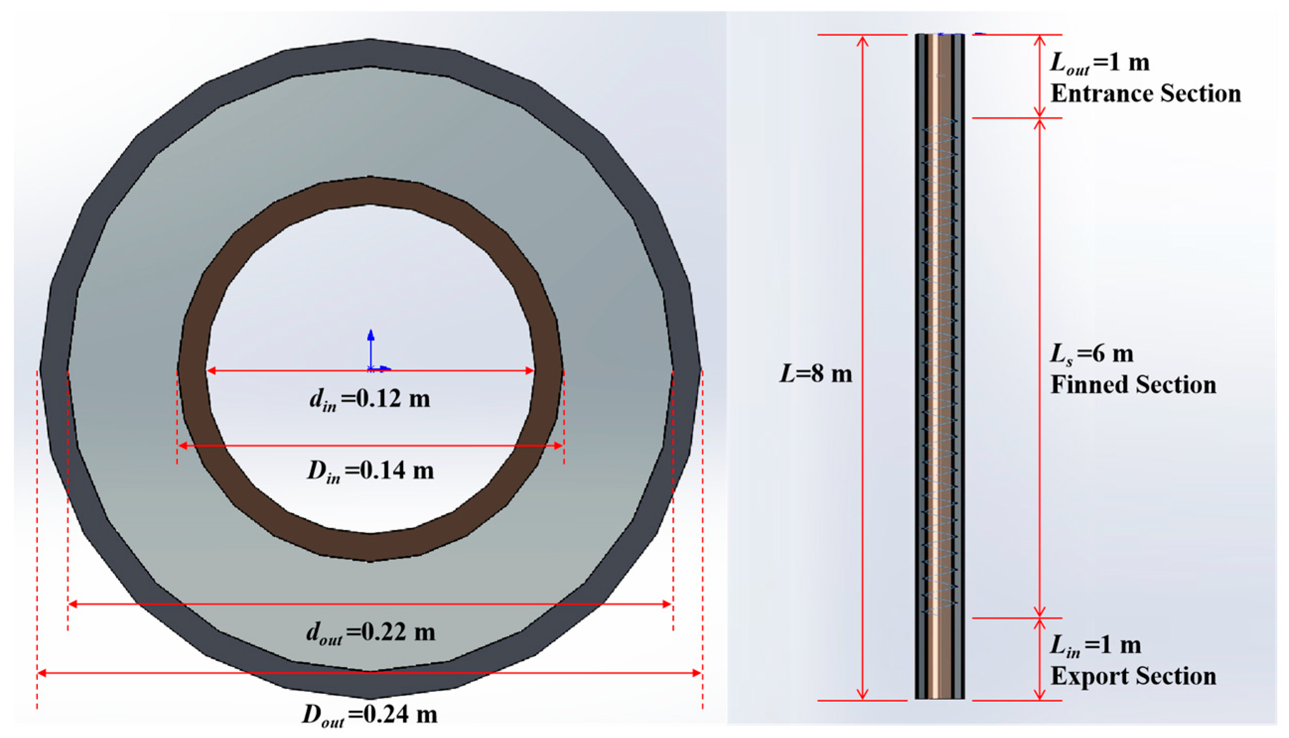
2.1. Modeling
- The flow within the heat exchanger is assumed to be three-dimensional and incompressible;
- While groundwater flow can influence heat extraction in CDHE systems, it is not the focus of this work. Therefore, only the thermal conductivity of the reservoir is considered, and the influences of groundwater flow are ignored;
- The thermophysical properties of the reservoir surrounding the wellbore are assumed to be isotropic and uniformly distributed;
- The reservoir temperature at the boundary of the simulation domain is considered constant.
2.2. Boundary Conditions
2.3. Definition of Parameters
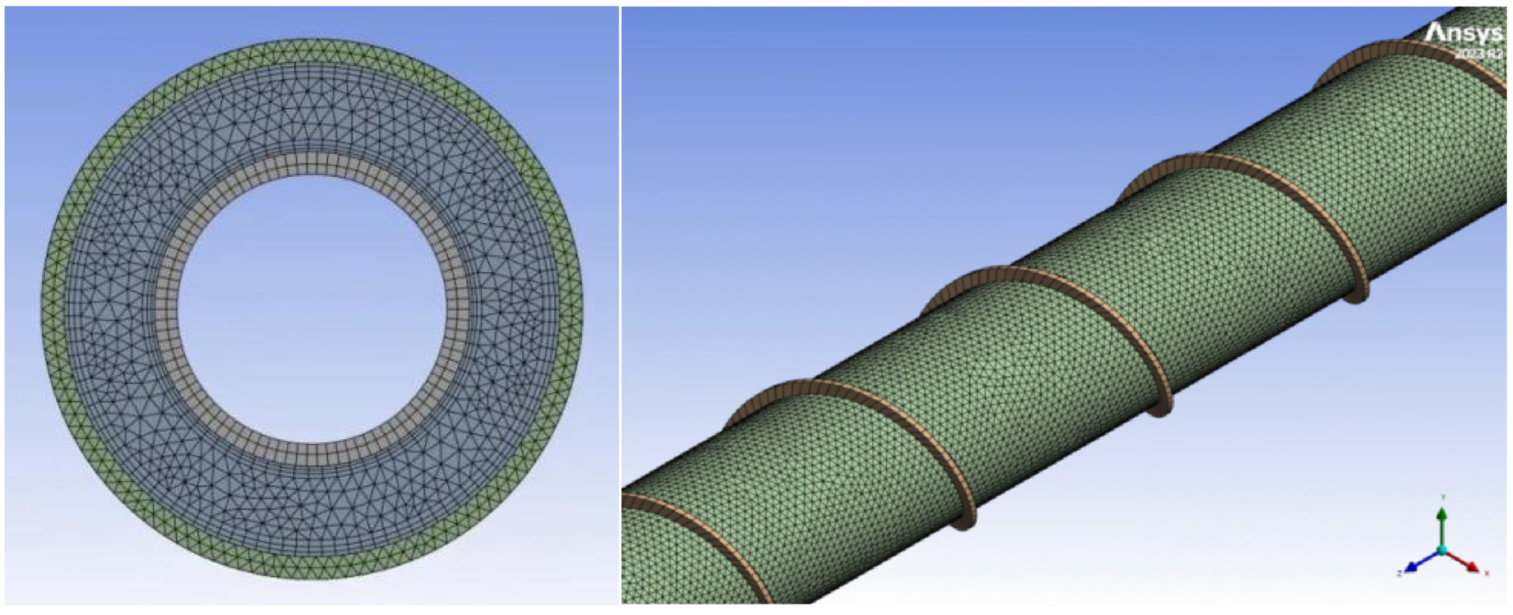
2.4. Grid Independence Test
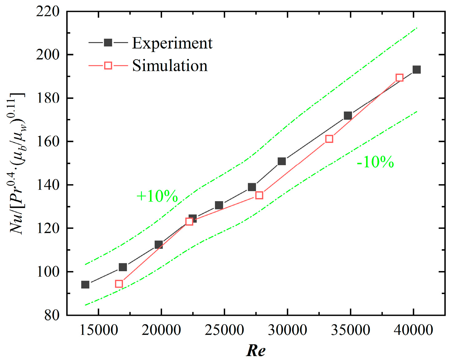
2.5. Validation of Computational Model
3. Results and Analysis
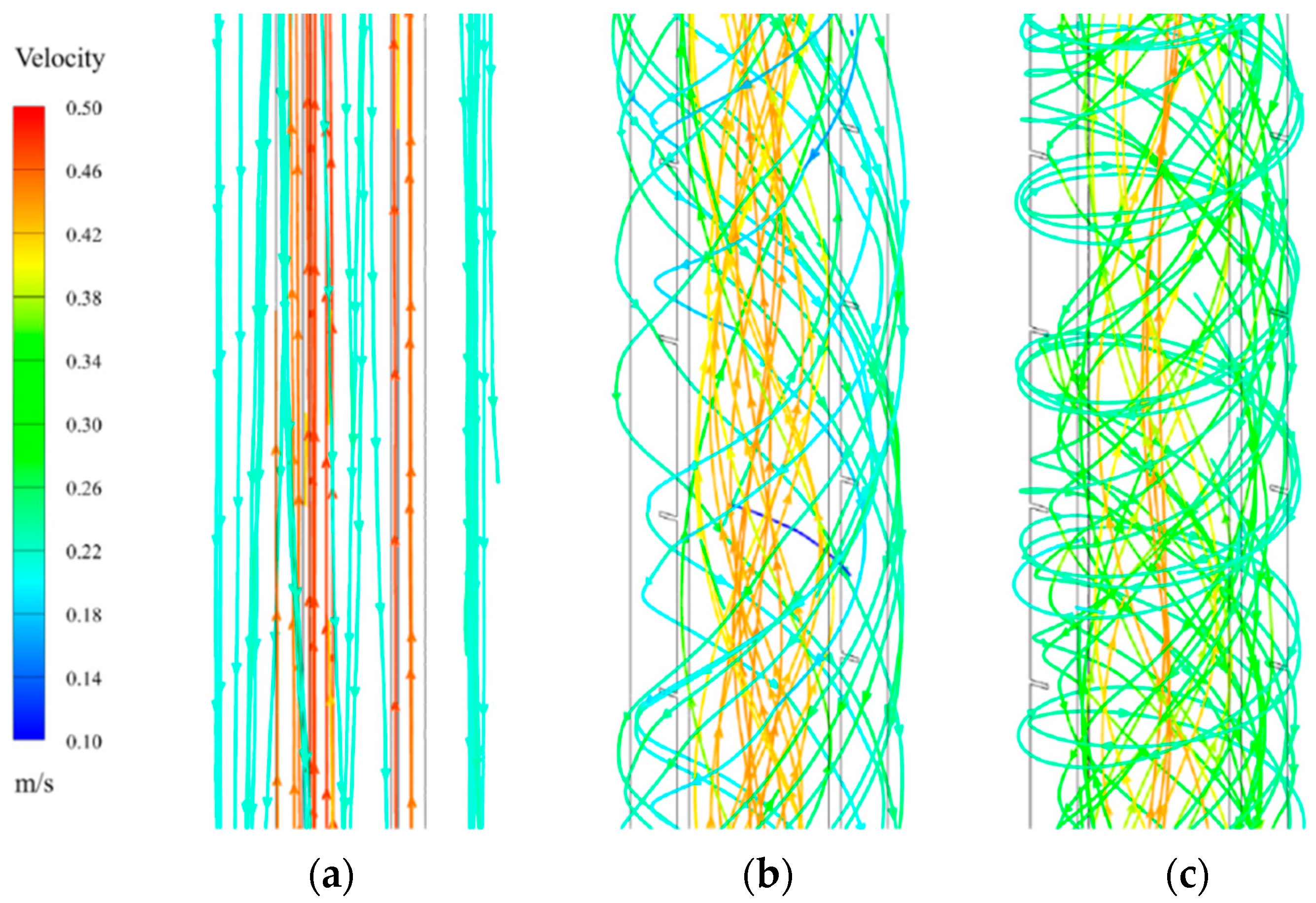
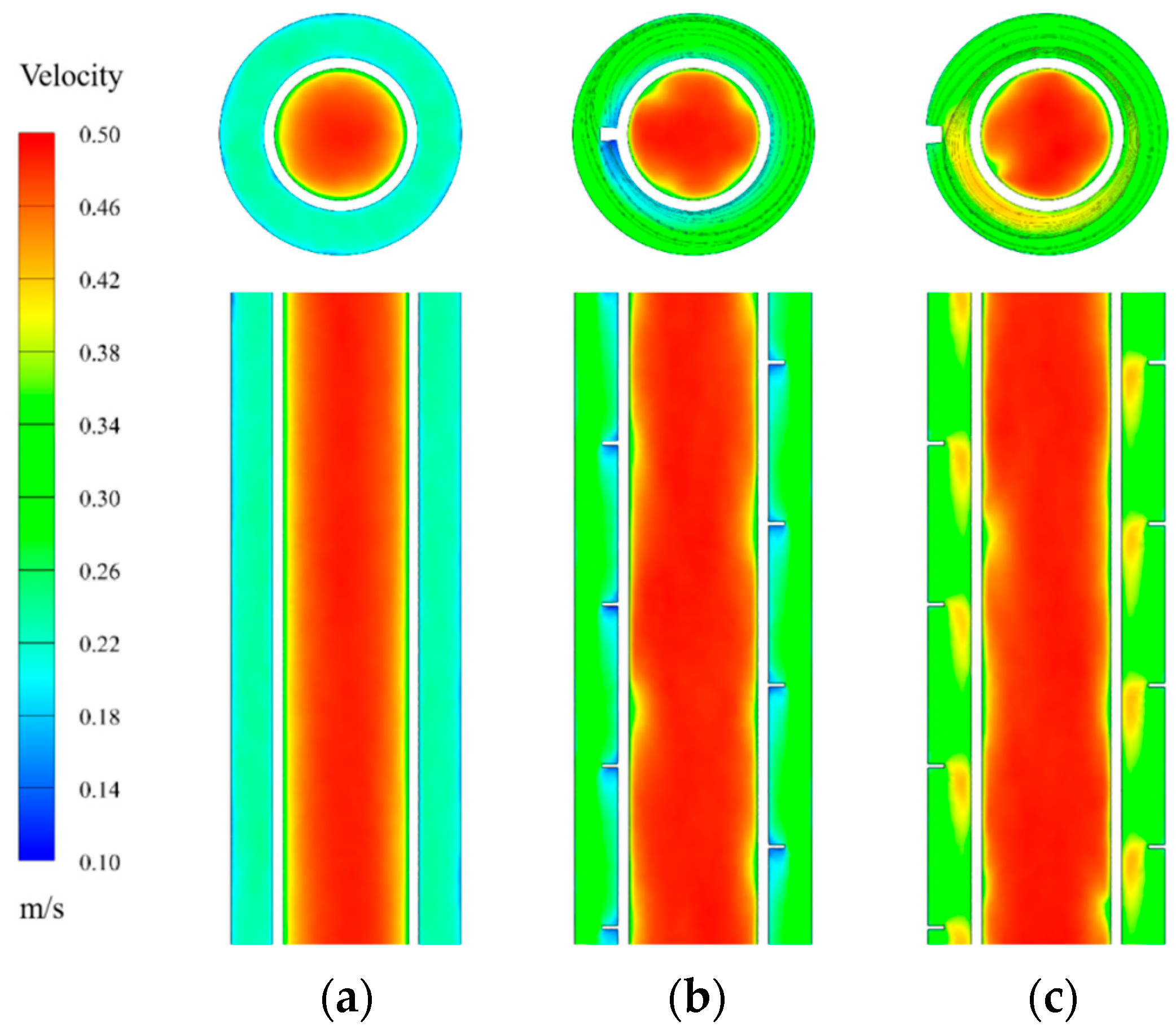
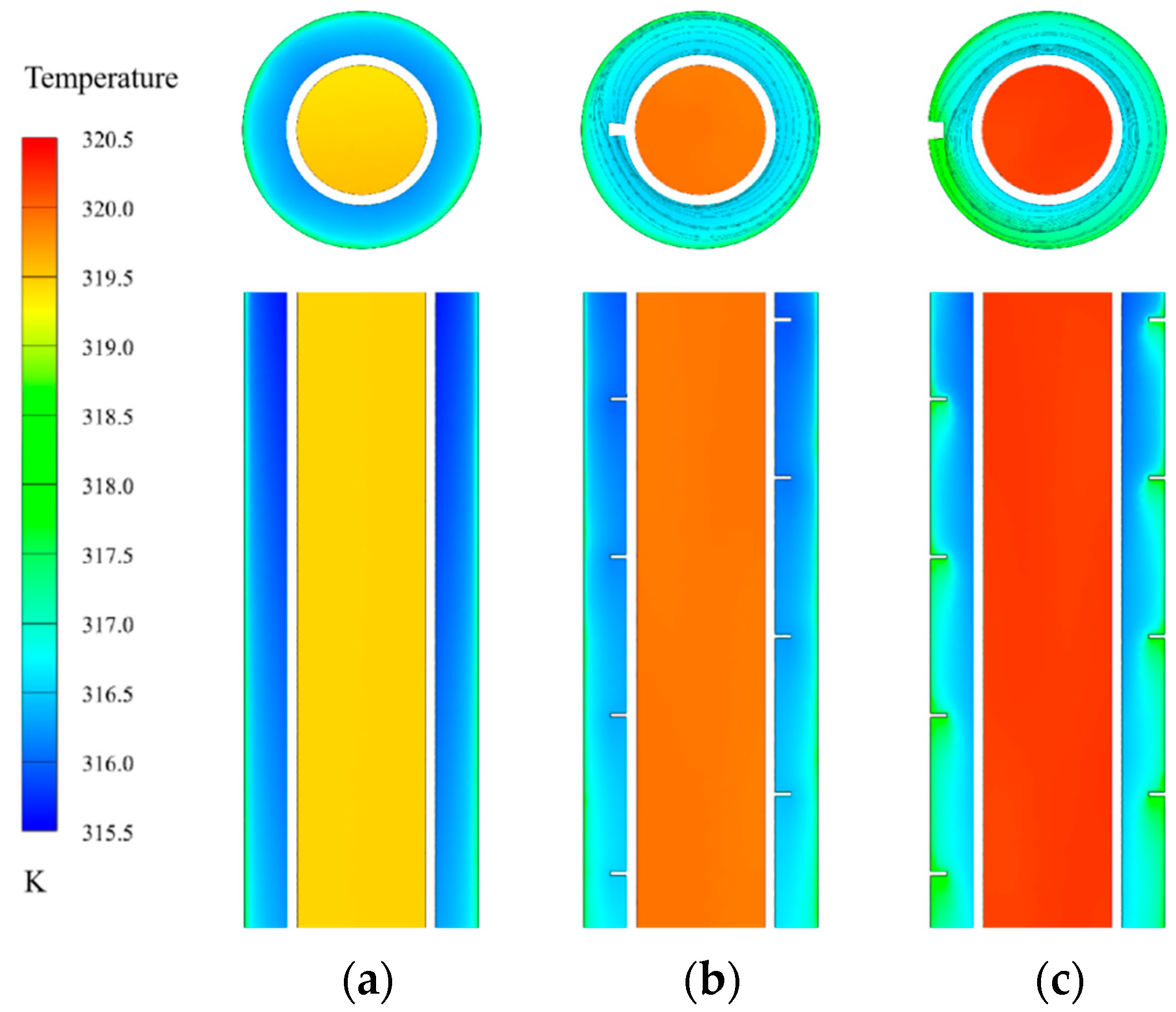
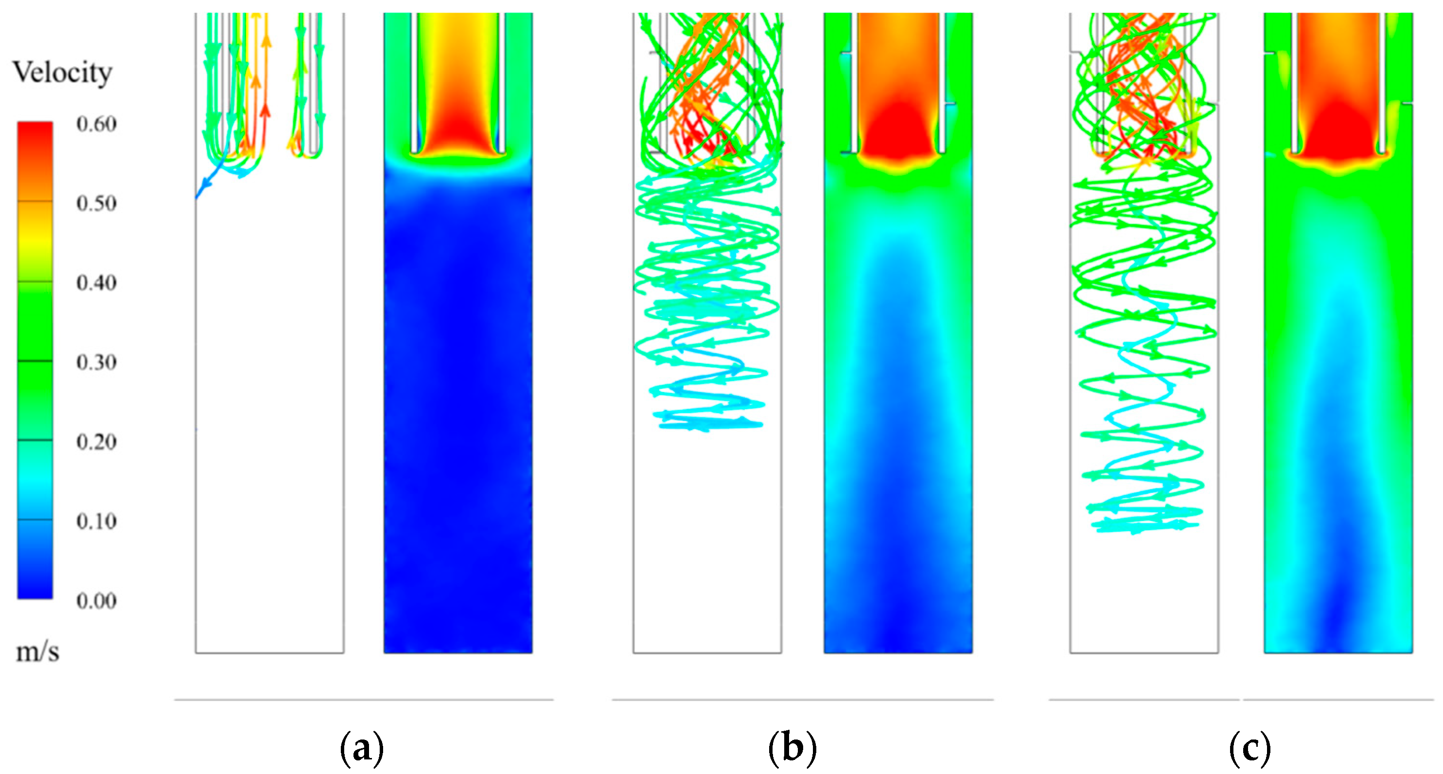
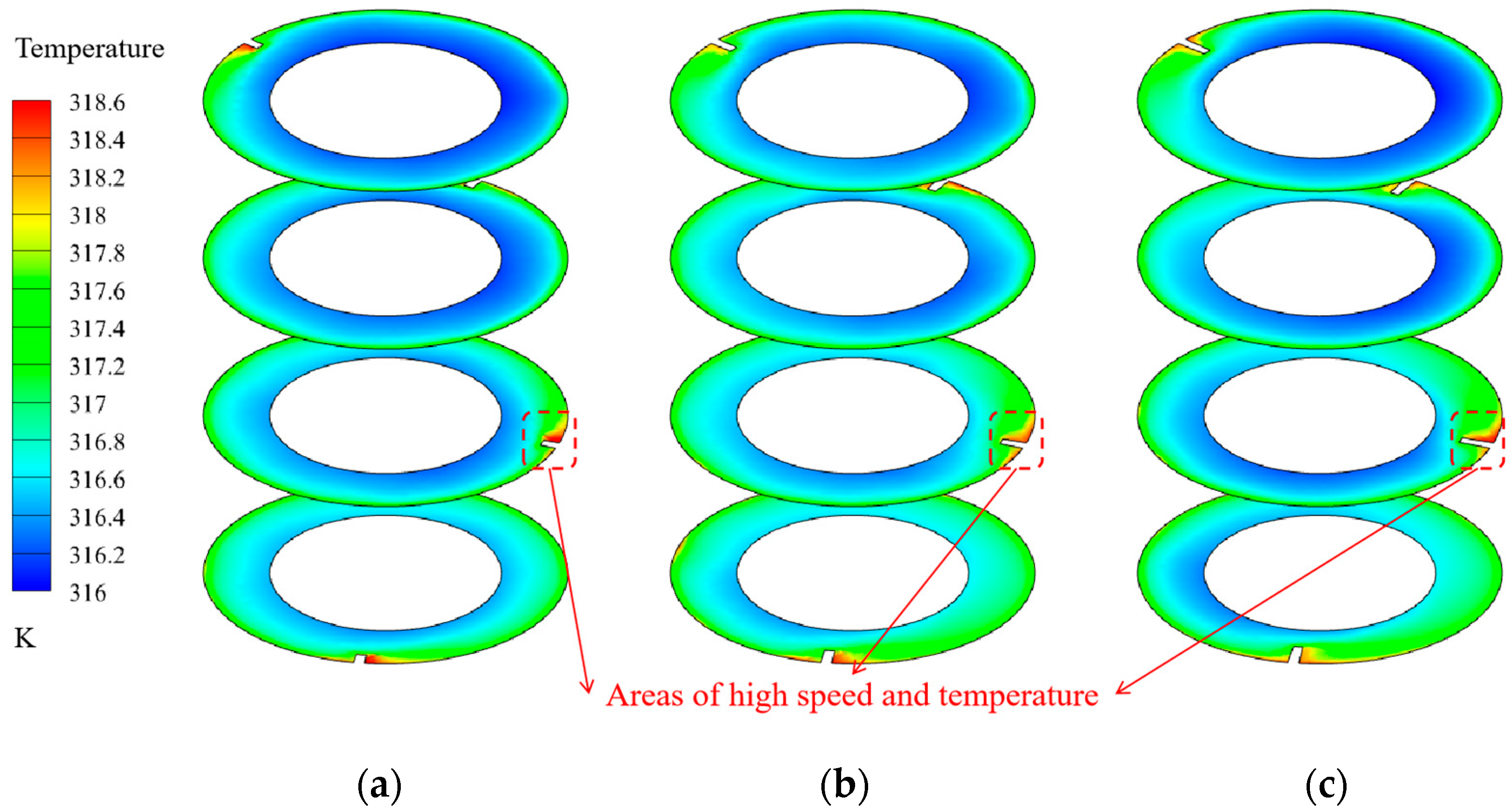
3.1. Flow and Heat Transfer Characteristics of Fins on the Outer Tube vs. the Inner Tube
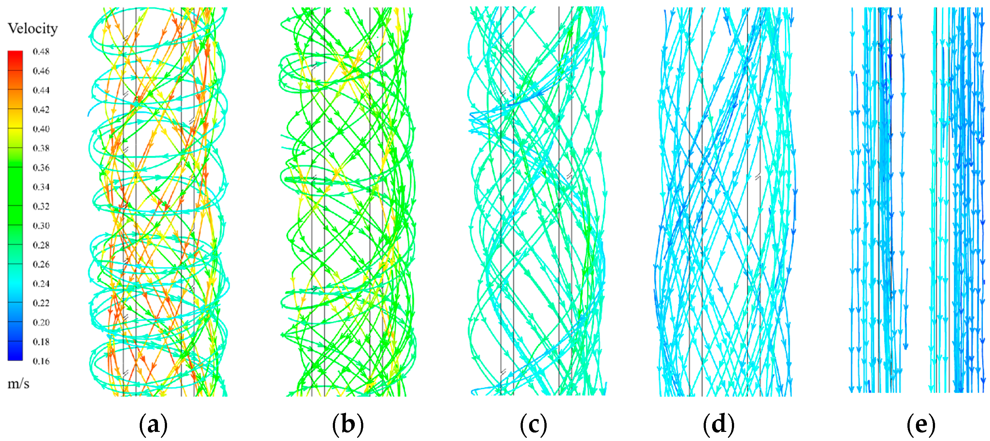
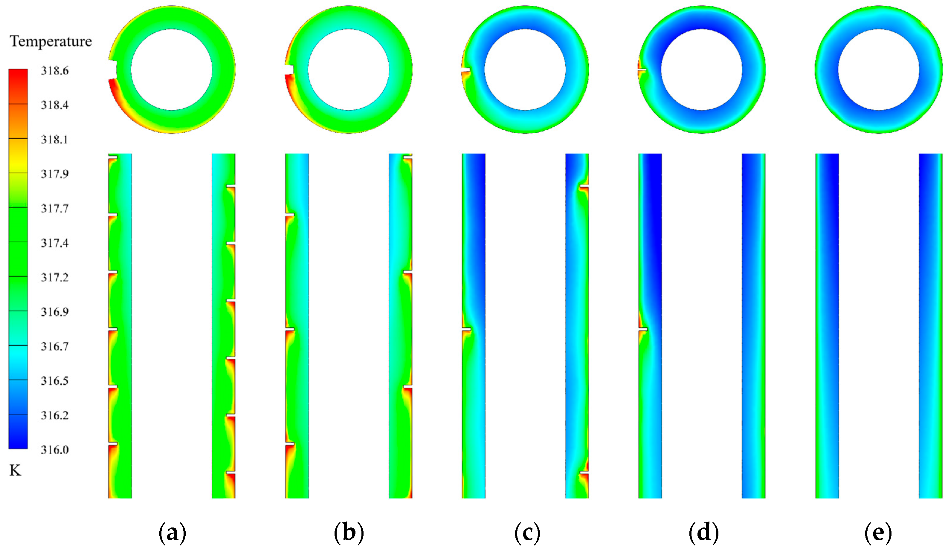
3.2. Influence of Fin Pitch on Heat Transfer Performance
3.3. Influence of Fin Height on Heat Transfer Performance
4. Conclusions
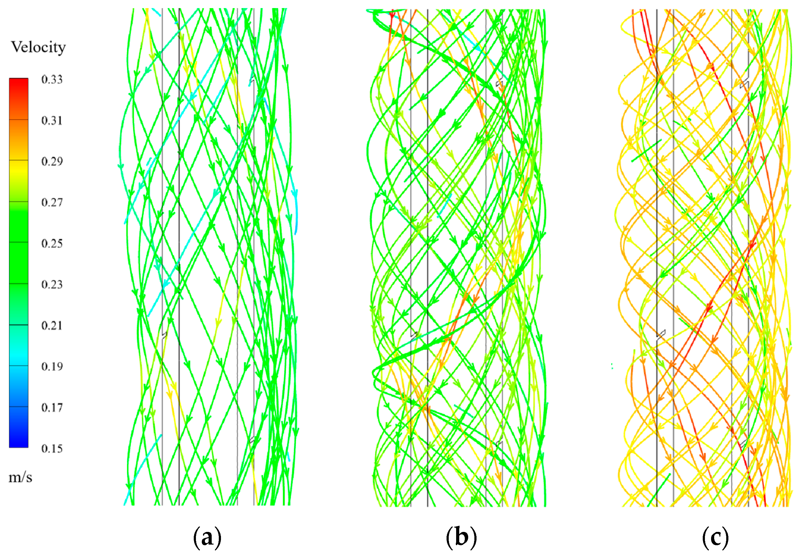
- Spiral fins induce circumferential flow within the annular channel, promoting enhanced fluid mixing and a more uniform velocity distribution near the bottom section of the CDHE. This significantly improves the heat transfer performance in the low-flow region;
- Spiral fins installed on the outer tube outperform those on the inner tube due to a larger spiral diameter and smaller rise angle. This configuration results in a 15% increase in turbulence intensity and a 9.7% increase in average velocity compared with fins mounted on the inner tube;
- The performance evaluation criteria (PEC) of the CDHE section first increases and then decreases with decreasing fin pitch, while it shows a slight decline with increasing fin height. The optimal performance is achieved with a fin height of 10 mm and a pitch of 500 mm, yielding a maximum PEC of 1.53.
Author Contributions
Funding
Data Availability Statement
Conflicts of Interest
References
- Meng, D.; Liu, Q.; Ji, Z. Effects of two-phase expander on the thermoeconomics of organic double-flash cycles for geothermal power generation. Energy 2022, 239, 122346. [Google Scholar] [CrossRef]
- Ren, Y.; Kong, Y.; Pang, Z.; Wang, J. A comprehensive review of tracer tests in enhanced geothermal systems. Renew. Sustain. Energy Rev. 2023, 182, 113393. [Google Scholar] [CrossRef]
- Liu, J.; Shao, C.; Yang, B.; Ngata, M.R.; Mwangomba, M.; Josephat, S.; Aminu, M.D. Advances in enhanced geothermal systems: Integrating laboratory, numerical and field insights. Appl. Therm. Eng. 2024, 249, 123350. [Google Scholar] [CrossRef]
- Brown, C.S.; Kolo, I.; Banks, D.; Falcone, G. A comprehensive review of deep borehole heat exchangers (DBHEs): Subsurface modelling studies and applications. Geotherm. Energy 2024, 12, 19. [Google Scholar]
- Zhang, K.; Cao, Z.; Deng, J. Design and performance optimization of a novel CAES system integrated with coaxial casing geothermal utilization. Appl. Therm. Eng. 2024, 256, 124111. [Google Scholar] [CrossRef]
- Akram, M.W.; Chen, Q.; Nortz, G.; Nortz, P. Experimental investigation and numerical modeling of an innovative horizontal coaxial ground heat exchanger (HCGHE) for geothermal heat pump applications. Appl. Therm. Eng. 2024, 257, 124492. [Google Scholar] [CrossRef]
- Alimonti, C.; Soldo, E. Study of geothermal power generation from a very deep oil well with a wellbore heat exchanger. Renew. Energy 2016, 86, 292–301. [Google Scholar] [CrossRef]
- Yu, H.; Lu, X.; Zhang, W.; Liu, J. Thermodynamic Analysis of an Increasing-Pressure Endothermic Power Cycle Integrated with Closed-Loop Geothermal Energy Extraction. Energies 2024, 17, 1756. [Google Scholar] [CrossRef]
- Wang, H.; Xu, Y.; Sun, Y.; Zhao, S. Heat extraction by deep coaxial borehole heat exchanger for clean space heating near Beijing, China: Field test, model comparison and operation pattern evaluation. Renew. Energy 2022, 199, 803–815. [Google Scholar]
- Jello, J.; Baser, T. Utilization of existing hydrocarbon wells for geothermal system development: A. review. Appl. Energy 2023, 348, 121456. [Google Scholar] [CrossRef]
- Davoodi, S.; Al-Shargabi, M.; Wood, D.A.; Slivkin, S.; Shishaev, G.; Rukavishnikov, V.S. Geothermal energy recovery from abandoned petroleum wells: A review of the challenges and opportunities. Sustain. Energy Technol. Assess. 2024, 68, 103870. [Google Scholar] [CrossRef]
- Song, X.; Xu, F.; Ji, J.; Shi, Y. Evaluation of the heat extraction performance of an abandoned well pattern in multilayer commingled production oil reservoirs. Natural Gas Ind. B 2022, 9, 578–587. [Google Scholar] [CrossRef]
- Chen, H.; Liu, H.; Yang, F.; Tan, H.; Wang, B. Field measurements and numerical investigation on heat transfer characteristics and long-term performance of deep borehole heat exchangers. Renew. Energy 2023, 205, 1125–1136. [Google Scholar] [CrossRef]
- Li, K.; Li, B.; Shi, S.; Wu, Z.; Zhang, H. Research and Application of Drilling Fluid Cooling System for Dry Hot Rock. Energies 2025, 18, 1736. [Google Scholar] [CrossRef]
- Brown, C.S.; Kolo, I.; Banks, D.; Falcone, G. Comparison of the thermal and hydraulic performance of single U-tube, double U-tube and coaxial medium-to-deep borehole heat exchangers. Geothermics 2024, 117, 102888. [Google Scholar] [CrossRef]
- Song, X.; Zheng, R.; Li, G.; Shi, Y.; Wang, G.; Li, J. Heat extraction performance of a downhole coaxial heat exchanger geothermal system by considering fluid flow in the reservoir. Geothermics 2018, 76, 190–200. [Google Scholar] [CrossRef]
- Gao, X.; Wang, Z.; Qiao, Y.; Li, T.; Zhang, Y. Effects of seepage flow patterns with different wellbore layout on the heat transfer and power generation performance of enhanced geothermal system. Renew. Energy 2024, 223, 120065. [Google Scholar] [CrossRef]
- Dai, C.; Li, J.; Shi, Y.; Zeng, L.; Lei, H. An experiment on heat extraction from a deep geothermal well using a downhole coaxial open loop design. Appl. Energy 2019, 252, 113447. [Google Scholar] [CrossRef]
- Oh, K.; Lee, S.; Park, S.; Han, S.; Choi, H. Field experiment on heat exchange performance of various coaxial-type ground heat exchangers considering construction conditions. Renew. Energy 2019, 144, 84–96. [Google Scholar] [CrossRef]
- Zheng, J.; Zhang, Y.; Huang, Y.; Liu, Q.; Cheng, Y.; Guo, J. Numerical investigation on heat transfer performance of the segmented cementing coaxial heat exchanger. Renew. Energy 2024, 220, 119633. [Google Scholar] [CrossRef]
- Quirosa, G.; Torres, M.; Becerra, J.A.; Jiménez-Espadafor, F.J.; Chacartegui, R. Energy analysis of an ultra-low temperature district heating and cooling system with coaxial borehole heat exchangers. Energy 2023, 278, 127885. [Google Scholar] [CrossRef]
- Lee, S.; Park, S.; Kang, M.; Oh, K.; Choi, H. Effect of tube-in-tube configuration on thermal performance of coaxial-type ground heat exchanger. Renew. Energy 2022, 197, 518–527. [Google Scholar] [CrossRef]
- Xia, Z.; Qin, S.; Tao, Z.; Jia, G.; Cheng, C.; Jin, L. Multi-factor optimization of thermo-economic performance of coaxial borehole heat exchanger geothermal system based on Levelized Cost of Energy analysis. Renew. Energy 2023, 219, 119513. [Google Scholar] [CrossRef]
- Brown, C.S.; Cassidy, N.J.; Egan, S.S.; Griffiths, D. Numerical modelling of deep coaxial borehole heat exchangers in the Cheshire Basin, UK. Comput. Geosci. 2021, 152, 104752. [Google Scholar] [CrossRef]
- Abdelhafiz, M.M.; Oppelt, J.F.; Brenner, G.; Hegele, L.A. Application of a thermal transient subsurface model to a coaxial borehole heat exchanger system. Geoenergy Sci. Eng. 2023, 227, 211815. [Google Scholar] [CrossRef]
- Asad, M.; Guida, V.; Mauro, A. Experimental and Numerical Analysis of the Efficacy of a Real Downhole Heat Exchanger. Energies 2023, 16, 6783. [Google Scholar] [CrossRef]
- Yu, C.; Zhang, Y.; Tan, Y.; Song, X.; Shi, Y.; Wang, G.; Huang, H. Performance comprehensive evaluation of downhole heat exchanger geothermal systems with various configurations and working fluids. Appl. Therm. Eng. 2022, 213, 118745. [Google Scholar] [CrossRef]
- Yuan, M.; Zhang, W.; Liu, G.; Zhang, X.; Yousif, M.Z.; Song, J.; Lim, H. Performance study of spiral finned tubes on heat transfer and wake flow structure. Int. J. Heat Mass Tran. 2022, 196, 123278. [Google Scholar] [CrossRef]
- Babu, C.R.; Kumar, P.; Roy, S.; Ganesan, R. A comprehensive review on compound heat transfer enhancement using passive techniques in a heat exchanger. Mater. Today Proc. 2022, 54, 428–436. [Google Scholar]
- Sheikholeslami, M.; Gorji-bandpy, M.; Ganji, D.D. Review of heat transfer enhancement methods: Focus on passive methods using swirl flow devices. Renew. Sust. Energy Rev. 2015, 49, 444–469. [Google Scholar] [CrossRef]
- Zhao, Y.; Lu, X.; Liu, L.; Zhang, B.; Wang, M.; Zhang, H. Heat transfer characteristics of external finned backfill coupled heat exchanger in mine. Geothermics 2024, 19, 102953. [Google Scholar] [CrossRef]
- Alnaqi, A.; Al-Rashed, A.; Alsarraf, J. Numerical investigation of the geometric parameters effect of helical blades installed on horizontal geo heat exchanger. Geothermics 2025, 125, 103169. [Google Scholar] [CrossRef]
- Roshani, M.; Hosseini, M.J.; Ranjbar, A.A.; Torbatinejad, A. Enhancing geothermal heat pump efficiency with fin creation and microencapsulated PCM: A. numerical study. J. Energy Storage 2024, 95, 112664. [Google Scholar] [CrossRef]
- Kim, D.; Son, J.Y.; Kim, T.K.; Kim, Y.W. Friction correlation of an offset strip fin modeled as porous medium for application to a geothermal heat exchanger. Geothermics 2020, 87, 101873. [Google Scholar] [CrossRef]
- Al-Kbodi, B.H.; Rajeh, T.; Zayed, M.E.; Li, Y.; Zhao, J.; Wu, J.; Liu, Y. Transient heat transfer simulation, sensitivity analysis, and design optimization of shallow ground heat exchangers with hollow-finned structures for enhanced performance of ground-coupled heat pumps. Energ. Buildings 2024, 305, 113870. [Google Scholar] [CrossRef]
- Al-Kbodi, B.H.; Rajeh, T.; Zayed, M.E.; Li, Y.; Zhao, J.; Rehman, S. Comparative numerical investigation on hollow-finned borehole heat exchangers: Multi-criteria optimization and dimensionless sensitivity analysis. Appl. Therm. Eng. 2025, 258, 124616. [Google Scholar] [CrossRef]
- Chen, K.; Zheng, J.; Li, J.; Shao, J.; Zhang, Q. Numerical study on the heat performance of enhanced coaxial borehole heat exchanger and double U borehole heat exchanger. Appl. Therm. Eng. 2022, 203, 117916. [Google Scholar] [CrossRef]
- Zhu, K.; Zeng, Y.; Wu, Q.; Wang, R.; Tu, K.; Yu, J.; Liu, X. Heat transfer performance of new efficient coaxial casing heat exchanger based on thermostatic thermal response test. Case Stud. Therm. Eng. 2022, 35, 102122. [Google Scholar] [CrossRef]
- Liu, Q.; Zhang, Y.; Zhang, X.; Luo, J.; Zheng, J.; Liu, Y.; Cheng, Y.; Lou, J. Numerical study on the heat transfer performance evaluation, flow characteristics, exergy efficiency, and entropy generation analysis of a novel coaxial geothermal heat exchanger. J. Build. Eng. 2024, 84, 108555. [Google Scholar] [CrossRef]
- Sun, L.; Fu, B.; Wei, M.; Zhang, S. Analysis of enhanced heat transfer characteristics of coaxial borehole heat exchanger. Processes 2022, 10, 2057. [Google Scholar] [CrossRef]
- Li, L.; Xu, P.; Li, Q.; Zheng, R.; Xu, X.; Wu, J.; He, B.; Bao, J.; Tan, D. A coupled LBM-LES-DEM particle flow modeling for microfluidic chip and ultrasonic-based particle aggregation control method. Appl. Math. Model. 2025, 143, 116025. [Google Scholar] [CrossRef]
- Xu, P.; Wang, C.; Li, L.; Tan, D.; Wu, H. Interlayer healing mechanism of multipath deposition 3D printing models and interlayer strength regulation method. J. Manuf. Process. 2025, 141, 1031–1047. [Google Scholar] [CrossRef]
- Yan, J.; Wang, S.; Yao, Y. Evaluation and Development and Utilization of Geothermal Resources in Oil Region; Petroleum Industry Press: Beijing, China, 2022; pp. 18–68. [Google Scholar]
- WEBB, R.L. Performance evaluation criteria for use of enhanced heat transfer surfaces in heat exchanger design. Int. J. Heat Mass Tran. 1981, 24, 715–726. [Google Scholar] [CrossRef]
- Jensen, J.; Michael, K. Technical Note Experimental investigation of turbulent heat transfer and fluid flow in internally finned tubes. Int. J. Heat Mass Tran. 1999, 42, 1343–1351. [Google Scholar] [CrossRef]


| Symbol | Parameters | Value and Unit |
|---|---|---|
| Dout | Outer diameter of outer tube | 120 mm |
| dout | Inner diameter of outer tube | 110 mm |
| Din | Outer diameter of inner tube | 70 mm |
| din | Inner diameter of inner tube | 60 mm |
| Ls | Length of the finned section | 6 m |
| Lin | Length of the entrance section | 1 m |
| Lout | Length of the export section | 1 m |
| P | Spiral pitch | 100–1000 mm |
| Hc | Height of the fins | 10–15 mm |
| b | Width of the fins | 5 mm |
| Parameters | Description | Inner Tube | Outer Tube |
|---|---|---|---|
| ρ | Density | 2300 kg·m−3 | 8030 kg·m−3 |
| cp | Heat capacity | 133 J·kg−1·K−1 | 502.8 J·kg−1·K−1 |
| λ | Thermal conductivity | 0.02 W·m−1·K−1 | 16.27 W·m−1·K−1 |
Disclaimer/Publisher’s Note: The statements, opinions and data contained in all publications are solely those of the individual author(s) and contributor(s) and not of MDPI and/or the editor(s). MDPI and/or the editor(s) disclaim responsibility for any injury to people or property resulting from any ideas, methods, instructions or products referred to in the content. |
© 2025 by the authors. Licensee MDPI, Basel, Switzerland. This article is an open access article distributed under the terms and conditions of the Creative Commons Attribution (CC BY) license (https://creativecommons.org/licenses/by/4.0/).
Share and Cite
Yang, X.; Liu, Q.; Lu, G. Heat Transfer Enhancement in Coaxial Downhole Heat Exchangers: Influence of Spiral Fins at the Bottom Section. Energies 2025, 18, 2361. https://doi.org/10.3390/en18092361
Yang X, Liu Q, Lu G. Heat Transfer Enhancement in Coaxial Downhole Heat Exchangers: Influence of Spiral Fins at the Bottom Section. Energies. 2025; 18(9):2361. https://doi.org/10.3390/en18092361
Chicago/Turabian StyleYang, Xinliu, Qiang Liu, and Gui Lu. 2025. "Heat Transfer Enhancement in Coaxial Downhole Heat Exchangers: Influence of Spiral Fins at the Bottom Section" Energies 18, no. 9: 2361. https://doi.org/10.3390/en18092361
APA StyleYang, X., Liu, Q., & Lu, G. (2025). Heat Transfer Enhancement in Coaxial Downhole Heat Exchangers: Influence of Spiral Fins at the Bottom Section. Energies, 18(9), 2361. https://doi.org/10.3390/en18092361