Review

Review on the Development and Applications of Permanent Magnet Vernier Motors

School of Electrical Engineering, Southeast University, Nanjing 210096, China
*
Author to whom correspondence should be addressed.
Energies 2025, 18(9), 2353; https://doi.org/10.3390/en18092353
Submission received: 11 April 2025 / Revised: 27 April 2025 / Accepted: 3 May 2025 / Published: 5 May 2025

Abstract

:
The permanent magnet vernier motor (PMVM) is characterized by high torque density and torque transmission capability. It is widely used in applications such as electric transportation and renewable energy generation, where low-speed, high-torque operation is preferred. This paper reviews the basic working principles and development of topologies, as well as the applications of PMVM. The methods to improve the torque density, power factor, and torque ripple of PMVM are discussed. Furthermore, the paper explores the future development trends of PMVM, providing theoretical foundations and technical support for their further research and engineering applications. In addition to these areas, PMVMs have gained significant attention in precise motion control systems, such as in robotics and CNC machines, where high torque and low vibration are critical. Vernier motors are also being explored in applications like actuators for aerospace systems and advanced medical equipment, where reliability and efficiency are paramount. The ability to precisely control the torque ripple and improve the power factor of PMVMs makes them ideal for use in these demanding environments.

1. Introduction

Permanent magnet motors are widely favored for their excellent performance and simple control methods [1,2,3]. Currently, low-speed, high-torque drive systems are required in fields such as renewable energy generation and electric vehicles. When using direct-drive permanent magnet synchronous motors (PMSMs), the speed is generally reduced and the torque increased by increasing the number of pole pairs in the motor. However, a larger number of pole pairs significantly increases the use of permanent magnets, making the motor bulky and less effective in specific applications. Therefore, traditional permanent magnet motors are generally equipped with mechanical gearboxes, which introduce additional losses, noise, and reliability issues into the system [4]. Against this background, the vernier motor was designed in the 1960s. However, it still relied on the principles of reluctance motors, and due to poor performance and low power factor, it did not attract much attention [5,6,7,8]. With the progress in permanent magnet materials, the development of power electronics, and advancements in magnetic gears [9,10,11,12,13] as well as field modulation theory, the permanent magnet vernier motor (PMVM) has once again attracted attention.
Recent research on PMVM has mainly focused on the following aspects:
  • Analysis of the operating principles of Vernier motors based on air-gap magnetic field modulation theory;
  • Methods for improving torque density and optimizing power factor;
  • Comprehensive optimization considering both cost and performance;
  • Research on conventional and special application scenarios.
In response to the above aspects, this paper summarizes the research outcomes on PMVMs in recent years. From the perspective of magnetic field modulation theory, this paper analyzes the topological evolution of PMVM, summarizes the application scenarios of PMVM, clarifies their advantages and limitations, and looks forward to their future development trends, aiming to provide directions for future research and industrial applications.

2. Analysis Methods of PMVM

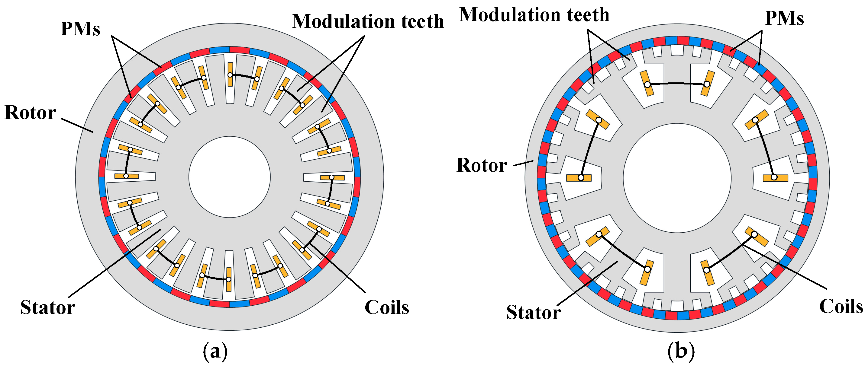
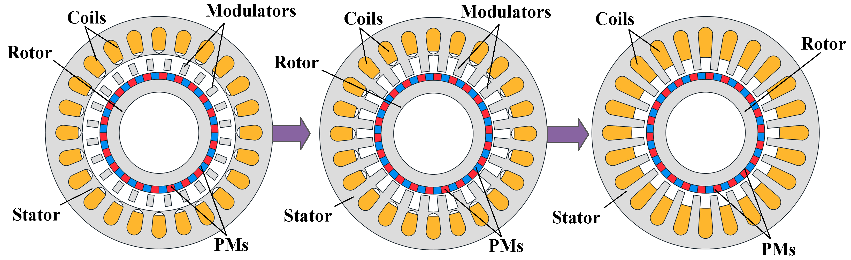
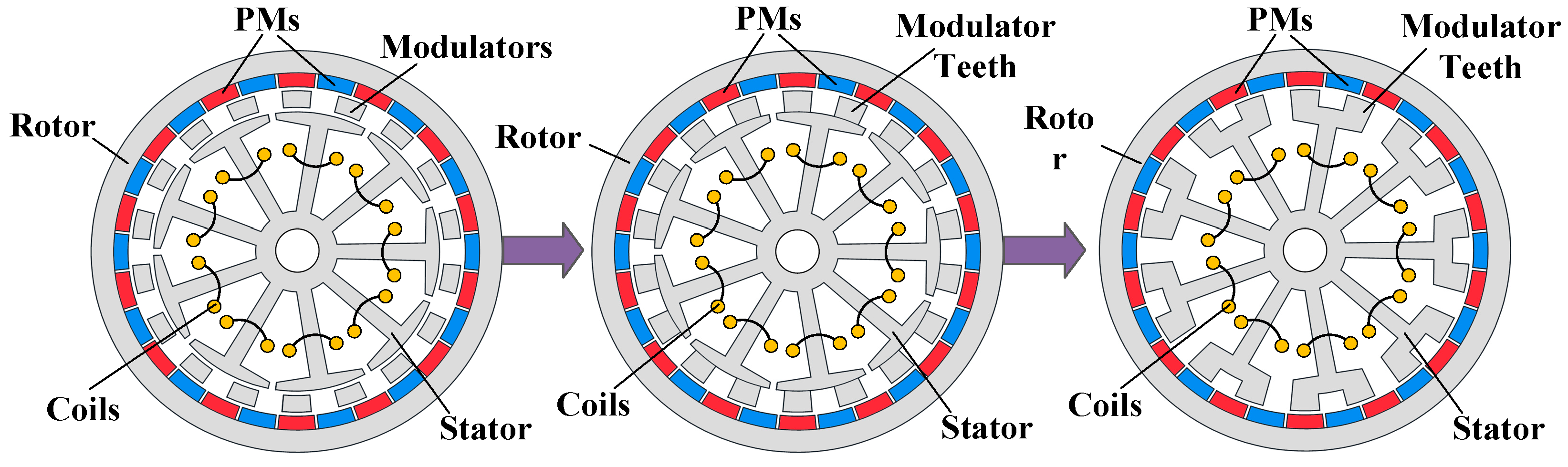
2.1. Topological Evolution of Vernier Motors

The PMVM, based on magnetic gears, uses a stationary stator structure to replace the high-speed inner rotor in the magnetic gear, and a winding is wound on the stator to absorb harmonics. Meanwhile, the flux-modulating magnetic blocks in the magnetic gear are converted into flux-modulation teeth and integrated into the stator of the PMVM. This transition from a dual air-gap structure to a single air-gap structure significantly reduces the difficulty of processing and assembly. The flux-modulation teeth function similarly to the flux-modulating magnetic blocks in the magnetic gear, thus achieving the transmission effect of the magnetic gear. Therefore, the PMVM can provide high torque density similar to that of a magnetic gear [14,15,16].
In order to improve the torque density and power factor or reduce the cost of PMVMs, various ideas were proposed, leading to the development of many topological structures for PMVM. When categorized according to the stator structure, PMVM can be broadly divided into two categories: open-slot structure and split-tooth structure [17,18], as shown in Figure 1. Studies have shown that compared to the split-tooth structure, the open-slot structure has lower torque ripple. However, on the other hand, the end windings of the split-tooth structure are shorter than those of the open-slot structure, which reduces copper losses and thus somewhat improves the efficiency.
Figure 2 explains the intermediate process of transitioning from a magnetic gear to a vernier motor approximation [18]. From the perspective of magnetic field modulation theory, the magnetic gears, pseudo-direct-drive permanent magnet motors, and PMVM can be classified as the same type of motor. Assuming that the number of stator teeth and the number of magnetic modulation blocks in the magnetic gear are the same, the magnetic modulation blocks of the magnetic gear can be aligned with the stator teeth. There is only a single air gap between them, so when combined, they form the PMVM. Figure 3 explains the evolution process from magnetic gears to the split-tooth PMVM [19]. The flux-modulating ring of the substituted magnetic gear motor is used as the rotor, forming a dual-rotor mechanical output. When the flux-modulating ring is fixed, it can be designed as a single part with the stator, forming the split-tooth PMVM, effectively reducing the complexity of the magnetic gear motor.

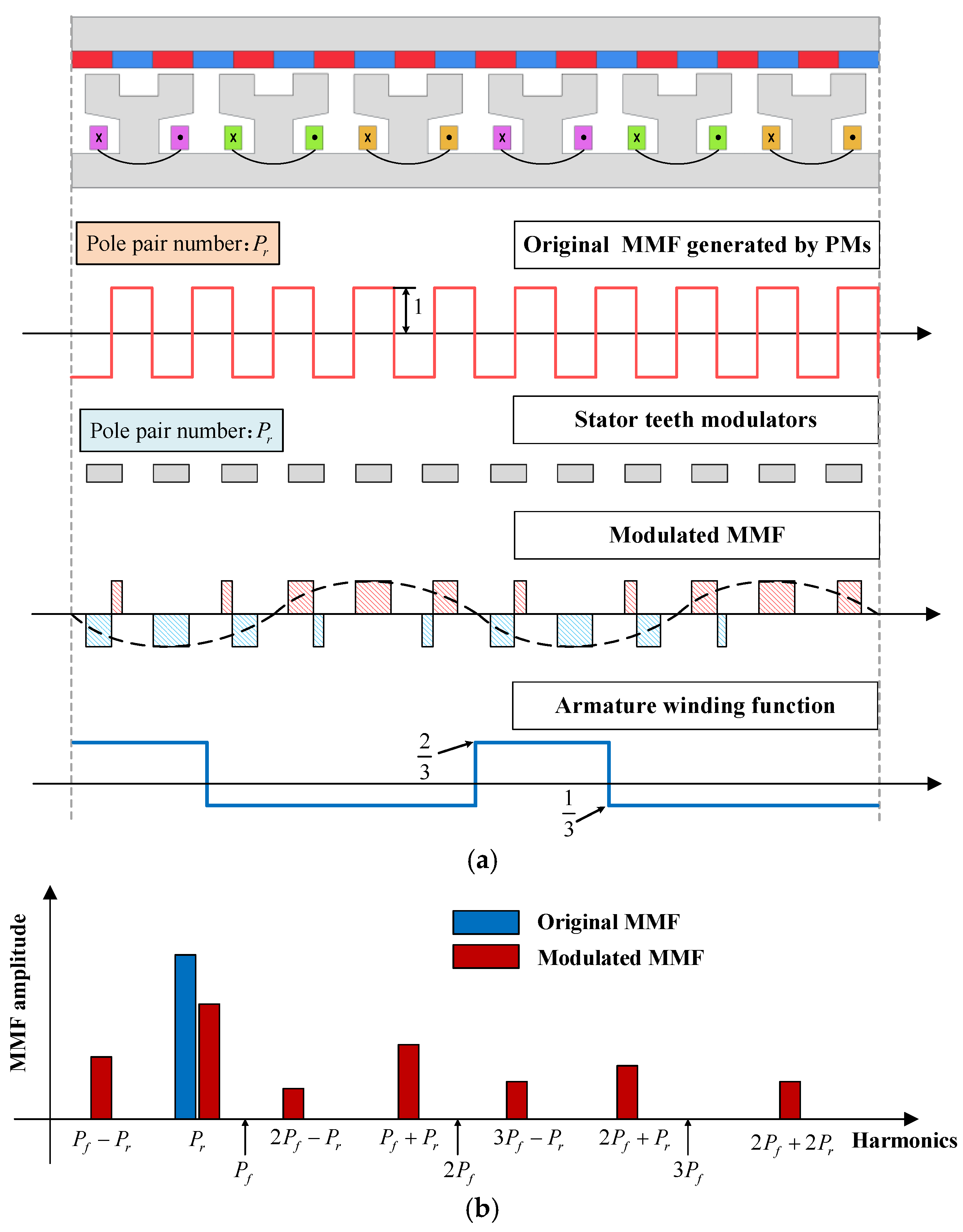
2.2. Working Principles of PMVM from the Prospect of Air-Gap Field Modulation Theory

The authors of [18] also analyzed the waveform of the air-gap magnetic flux density and proved that magnetic gears and PMVM share the same operating principle—magnetic field modulation theory—indicating that magnetic gears can transition into PMVM. Additionally, having too many stator slots in the motor will cause an increase in cogging torque, while having too narrow slot widths will make the processing and winding more difficult. Therefore, the split-tooth PMVM was developed to solve this issue [20]. By satisfying the relationship between the number of modulation poles and the stator–rotor pole pairs, the motor can have more slot space and reduce the amount of stator material used. The authors of [21,22] divided the magnetic field modulation motor into three elements: (1) excitation source, (2) modulation operator, and (3) filter, establishing a unified magnetic field modulation theory that can be applied to various electromagnetic devices, providing theoretical support for the research of magnetic field modulation theory in induction motors, DC motors, and other types of motors.
A typical 6-slot, 10-pole split-tooth PMVM is used below to explain its modulation process in detail. The specific modulation process is shown in Figure 4a. First of all, the original permanent magnet’s magnetomotive force is modulated through the rotor yoke. Then, the modulated air-gap magnetomotive force is obtained through simple stator salient pole modulation. The final electromagnetic torque is generated by the interaction between the modulated air-gap magnetomotive force and the armature magnetomotive force generated by the armature windings. At the same time, Figure 4b shows the corresponding harmonic spectrum.

3. Methods for Increasing the Torque of PMVM
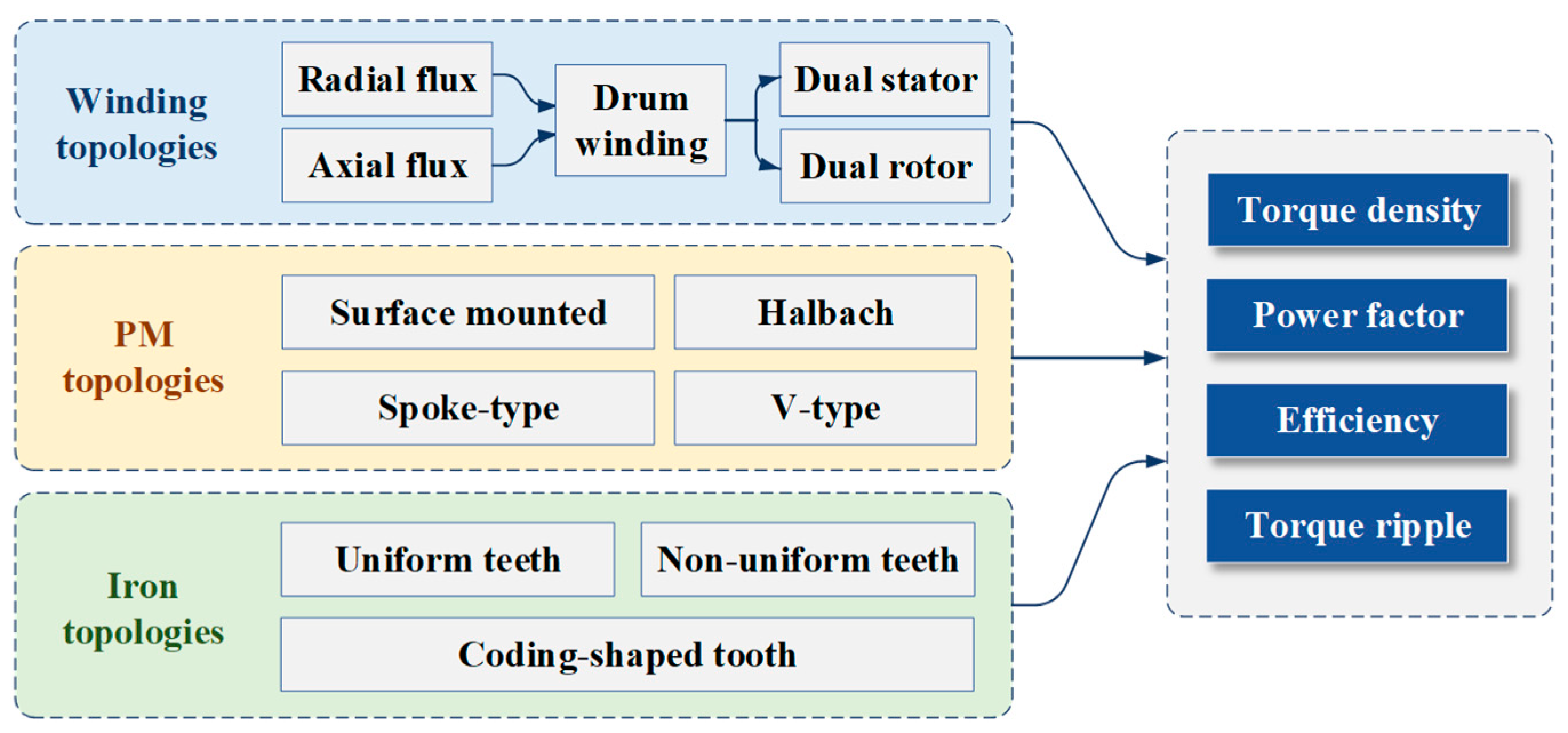
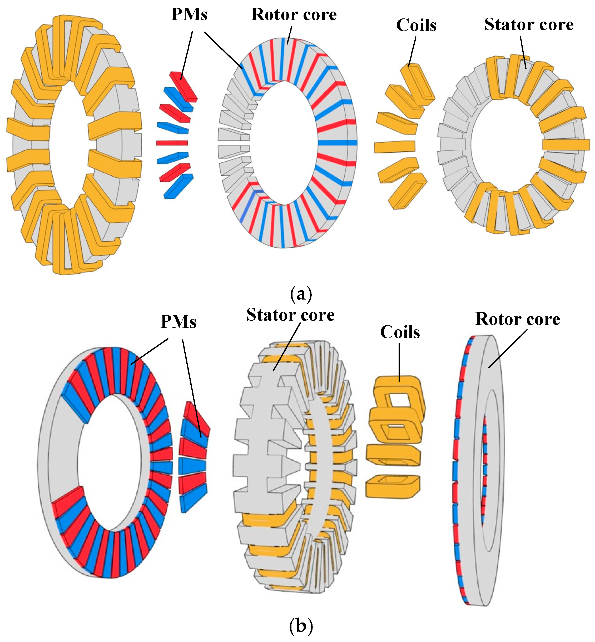
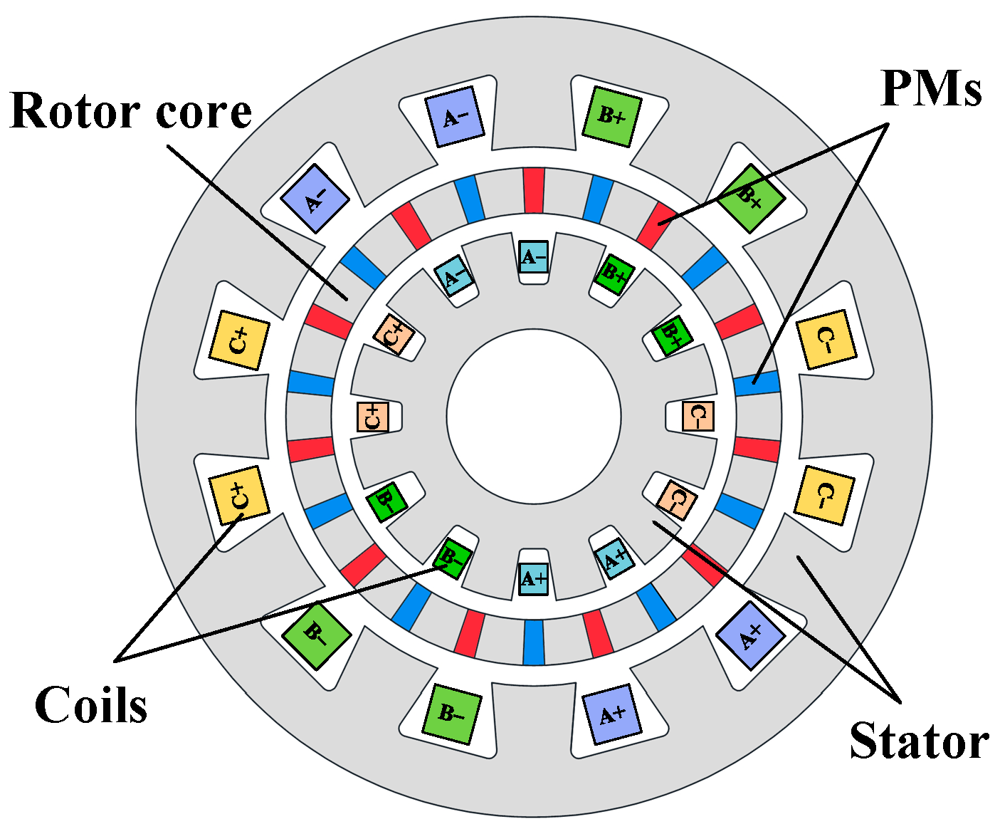
This section summarizes the topologies of the PMVM from three aspects: winding type, permanent magnet type, and stator–rotor core, as given in Figure 5.

3.1. Winding Type

The torque of the PMVM is related to the motor size, phase current magnitude, and the harmonic amplitudes of the air-gap magnetic flux density [23]. Using multiple rotors [24,25] or multiple stators [26,27] is the most direct and simple method. As shown in Figure 6, using a toroidal winding can save a large amount of end space and improve the torque density. However, as an axial flux motor, to avoid unbalanced radial magnetic pull, higher assembly precision is required. Figure 7 shows a radial magnetic field PMVM with toroidal windings. Although the structure in Figure 7a can increase the torque to some extent, it does not fully utilize the advantages of the ring winding. The coil type in Figure 7b is also usually called the drum winding, which is more suitable for PMVM with fewer stator teeth.

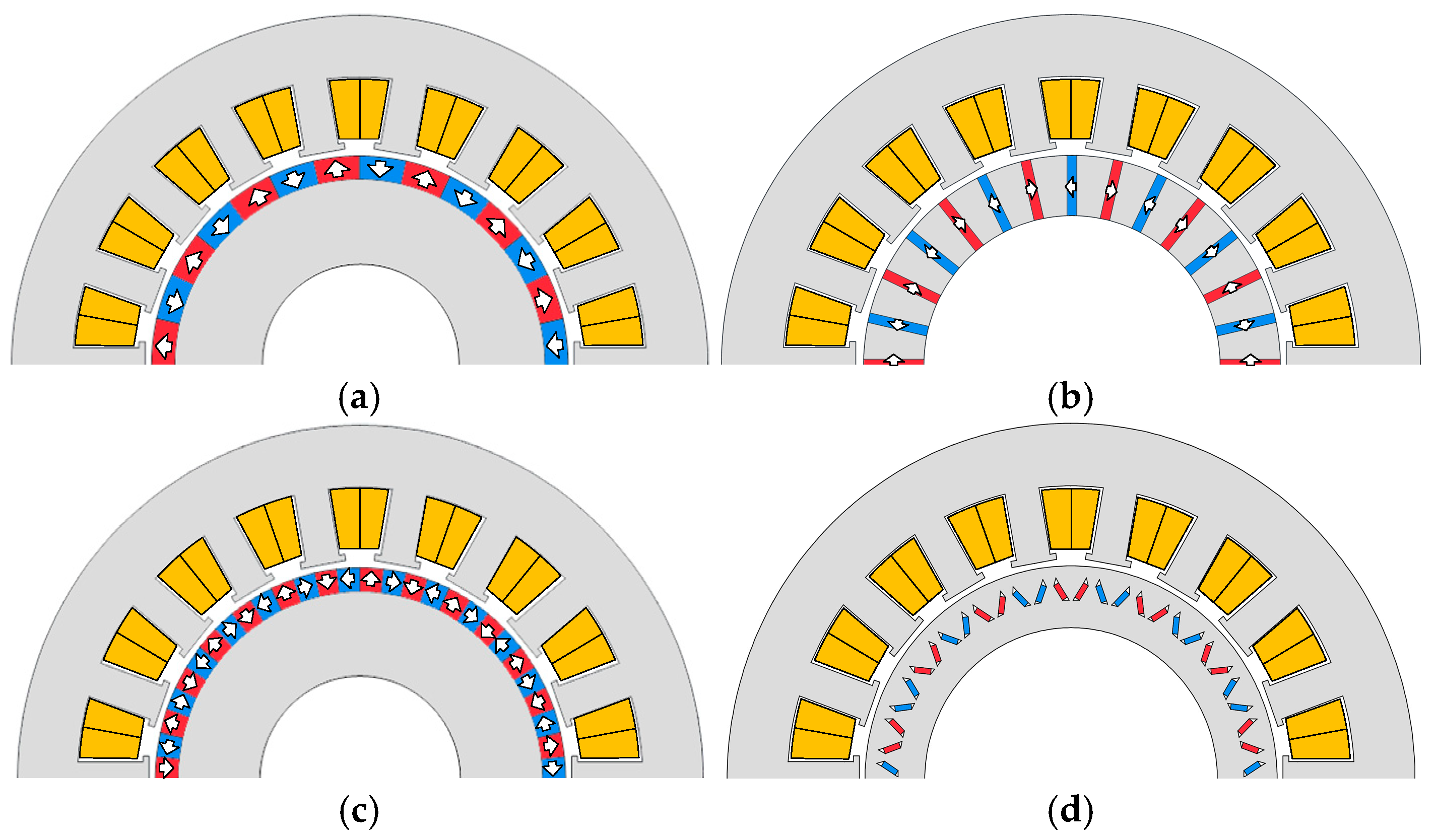
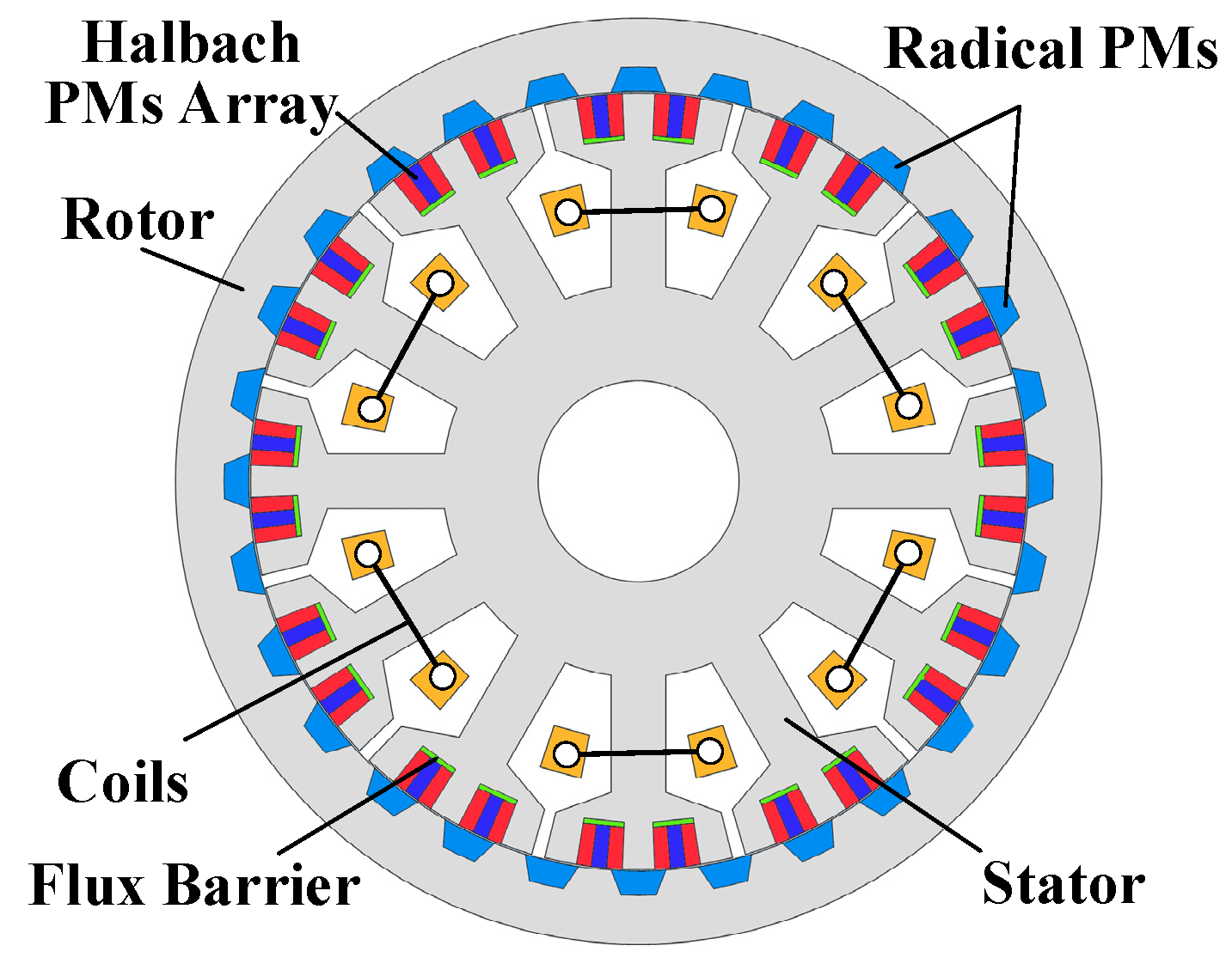
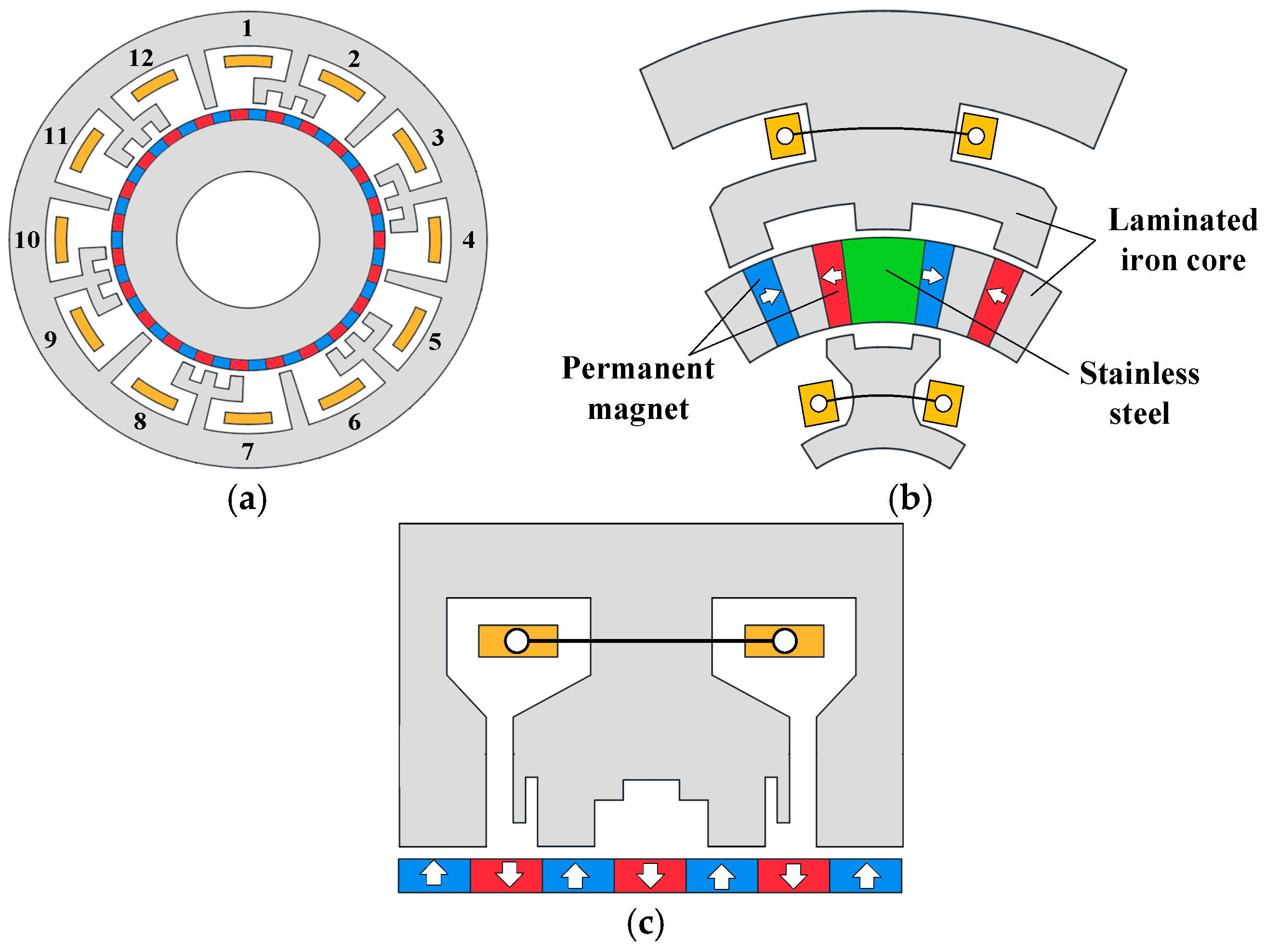
3.2. Permanent Magnet Type

Compared to the stator structure, the rotor structure of the PMVM is more varied. The main difference in these rotor structures lies in the arrangement of the permanent magnets, which can generally be categorized as surface-mounted magnets [28,29,30], spoke-type magnets [31,32], Halbach-type magnets [33,34,35,36], and V-shape magnets [37,38], as shown in Figure 8. Compared to surface-mounted magnets, using embedded Spoke, Halbach, or V-type permanent magnets can effectively improve the torque density and power factor. References [32,39,40] introduce magnetic bridges in spoke-type and Halbach-type PMVMs, placing two sets of permanent magnets on the stator and rotor, as shown in Figure 9, forming a double-sided PM configuration. This configuration effectively reduces leakage flux in the inner side of the spoke-type PM and enhances the fundamental and lower-order harmonic components of the air-gap flux density, leading to a significant increase in torque. Figure 10 shows a flux-concentrating dual-stator PMVM [30,41], where the teeth and slots of the inner and outer stators are aligned. This ensures that the PMs in the middle always pass through a magnetic path and interact with the windings, contributing to the generation of torque. This structure solves the issue of low power factor in PMVMs and further improves the power density of the motor. Reference [42] proposes a misaligned structure for the PMs in surface-mounted axial flux motors, which can effectively enhance system performance.

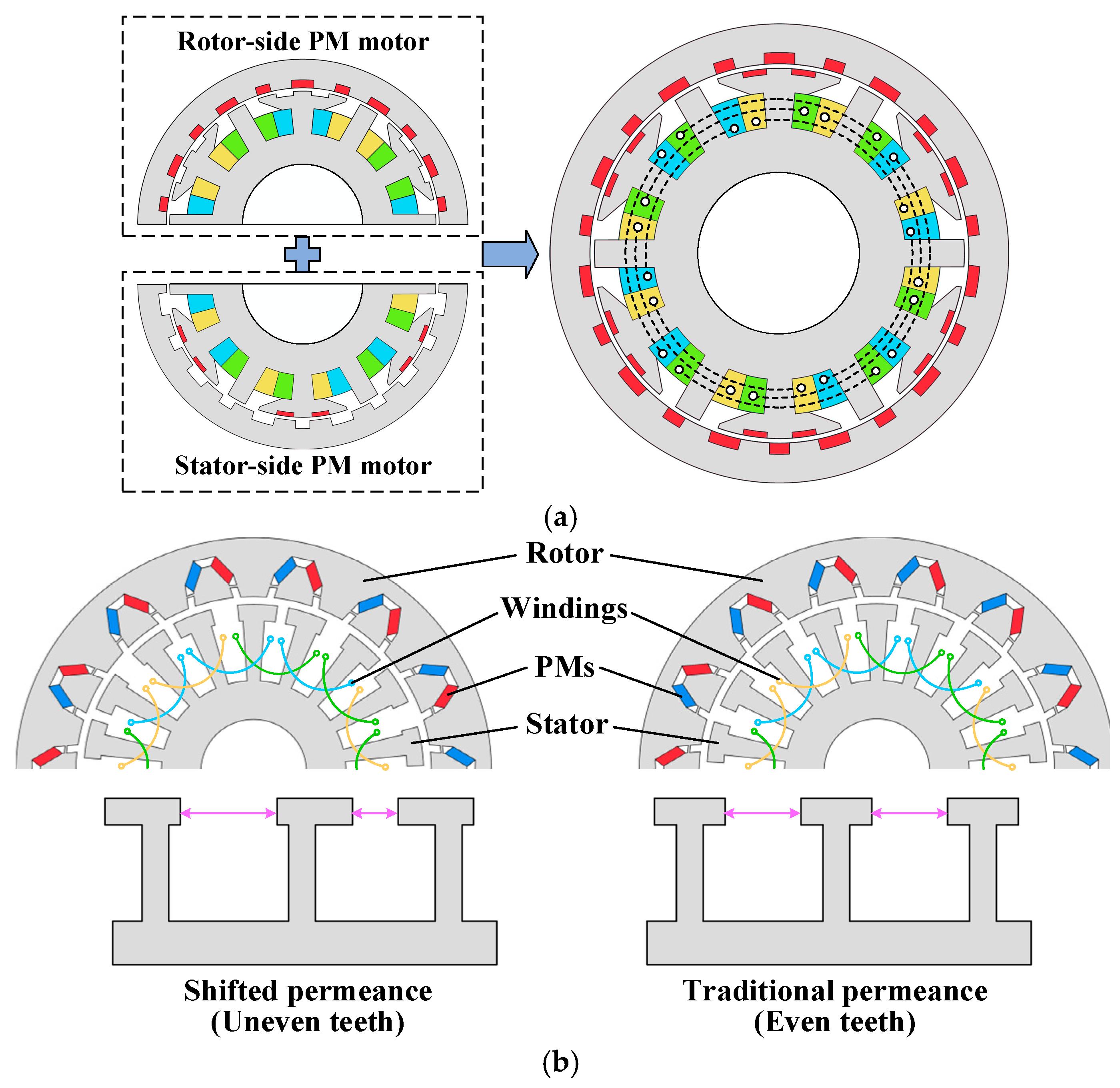
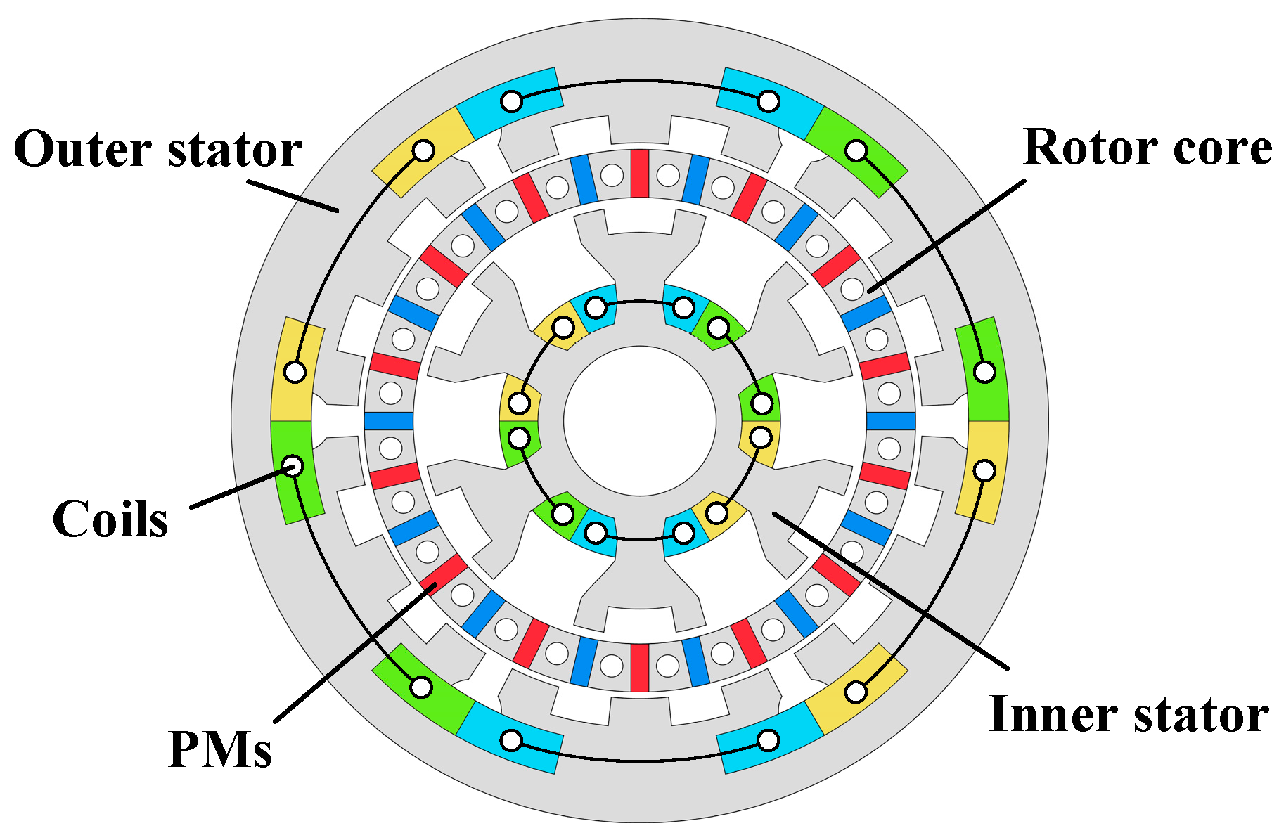
3.3. Stator Core Shape

The stator structure plays an important role in optimizing the torque of PMVMs. It affects the number of modulation poles and the distribution of circumferential magnetic permeability, which in turn impacts the saturation of magnetic flux lines and significantly influences the air-gap magnetic flux density distribution and its amplitude in PMVM. Reference [43] compared uniformly distributed and non-uniformly distributed modulation teeth in PMVMs, as shown in Figure 11a. The study shows changes in the modulation teeth alter the phase difference of the motor slot electromotive force, improving the motor’s winding factor, back electromotive force, and electromagnetic torque, while reducing torque ripple.
Figure 11b shows the PMVM where the width and pitch of split teeth are unequal [44], indicating that, compared to the equal-width case, the back electromotive force and torque density increase, and torque ripple is reduced. Reference [19] studied a stator design where the tooth pitch is larger than the motor slot pitch, altering the air-gap magnetic permeability to introduce different operating harmonics. This increases the torque density by 20% compared to traditional non-overlapping winding PMVM. Reference [45] suggested segmenting the stator of an axial flux motor to reduce the impact of low-order EMF and improve the motor’s performance. Reference [46] proposed a coded stator tooth PMVM, as shown in Figure 11c, which can modulate the magnetic field in the air gap, thereby enhancing the motor’s performance.

3.4. Comprehensive Comparison of the Typical PM Motors

Table 1 presents the comparison of various permanent magnet motor types, revealing distinct advantages and limitations suited for different applications. The PMVM excels in high torque density and low-speed, high-torque applications, making it ideal for precision positioning and robotics, though it suffers from low power factor and high manufacturing costs. The Brushless DC Motor (BLDC) is efficient and cost-effective for high-speed applications but requires complex control systems. The Permanent Magnet Synchronous Motor (PMSM) offers high precision and efficiency, particularly for industrial automation, though it is costly. Series and Shunt motors provide stable operation in simpler applications, with Series motors often facing efficiency challenges. The Synchronous Reluctance Motor (SRM) is suitable for low-speed, high-torque applications but requires sophisticated control strategies. Future research in these motors will likely focus on improving power factors, control precision, and cost-effectiveness to expand their use across various industries.

4. Challenges and Optimization Methods for PMVM

4.1. Challenges and Limitations of PMVMs

While PMVMs offer high torque density and a compact design, they also come with several notable disadvantages:
  • Low power factor: PMVMs often exhibit a relatively low power factor due to the magnetic gearing effect, which leads to inefficient utilization of the input electrical power.
  • Complex structure: The motor’s intricate design, including flux-modulation poles and specialized stator–rotor configurations, increases manufacturing difficulty and cost.
  • High dependence on rare-earth magnets: PMVMs typically require a large number of small-sized rare-earth permanent magnets, such as NdFeB, which are expensive and sensitive to temperature.
  • Manufacturing and assembly challenges: The use of many small magnet segments demands high precision in machining, alignment, and assembly, complicating large-scale production.
  • Thermal management issues: Due to high flux density and concentrated magnetic fields, PMVMs may face localized heating, requiring effective thermal management strategies.
  • Limited experimental validation: Many PMVM designs are still in the research or prototype stage, with limited validation under real-world load variations and long-term operation.
These drawbacks need to be addressed through design optimization, cost-effective material choices, and advanced control techniques to make PMVMs more viable for commercial applications.

4.2. Improving Power Factor

Compared to traditional PMSMs, PMVMs exhibit a lower power factor due to the high harmonic content in the air-gap magnetic field. Since only a small portion of these harmonics contribute to torque production and active power, substantial reactive power is generated. Consequently, enhancing the stator–rotor magnetic field interaction and optimizing the magnetic field modulation structure are two effective strategies for improving the power factor.
Reference [47] compared the performance of slotted PMVMs and split-tooth PMVMs, concluding that the power factor of the split-tooth PMVM is particularly low, around 0.5. Although using a slotted PMVM increases core loss and winding end length, it can significantly improve the power factor and torque density. Reference [48] doubled the number of slots in a 9-slot concentrated winding motor, turning it into an 18-slot motor with a 2-pitch, effectively expanding the winding pitch from 1 to 2. This reduced the space harmonic components of the armature reaction and phase inductance, thus improving the power factor. This conclusion also aligns with the comparison between FSCW and ISDW in reference. Reference [49] proved that a dual-stator structure has lower phase inductance compared to a single-stator PMVM, leading to a higher power factor. References [33,34,35,36] have demonstrated that a Halbach-type PM can improve the power factor by reducing leakage flux. References [50,51] adopted a hybrid excitation structure to further enhance the air-gap magnetic flux density, with DC bias current providing additional active excitation, resulting in a higher power factor. This was also illustrated by references [52,53] using S-type modulation poles for magnetic gear, and we believe this S-type structure provides great inspiration and can be used in a PMVM to improve the power factor. The segmented stator is proposed to interrupt the magnetic path of low-order non-working harmonics, thus improving the power factor [54,55].

4.3. Reducing Torque Ripple

In PMVMs, torque ripple arises from non-working harmonics in the air gap. The approach to suppressing this is similar, which involves improving the stator–rotor magnetic field and adjusting the distribution of the air-gap magnetic flux density harmonics by altering the air-gap magnetic permeability. Reference [56] introduced a dual-sided-magnets PMVM with alternating stator teeth. It utilizes the cooperative effect of the dual-sided magnetic field to improve the air-gap magnetic flux density and reduce the torque ripple, as shown in Figure 12a. Reference [57] modified the stator teeth into an unequal pitch to introduce shifted magnetic permeability, thereby suppressing torque ripple, as shown in Figure 12b. Reference [58] proposed a star–delta hybrid connection method to effectively reduce the magnetic field harmonics in the armature field associated with torque ripple. References [59,60] proposed changing the shape of the permanent magnet to adjust the harmonic composition of the permanent magnet’s magnetomotive force, as shown in Figure 13. In reference [61], a motor similar to a homopolar motor was introduced, where the alternating-pole motor is segmented axially to reduce the torque ripple. Reference [62] similarly proposed a modular stator fractional-slot concentrated winding PMVM, which segments the stator using non-magnetic materials to interrupt the magnetic path of non-working magnetic flux harmonics in the stator.

4.4. Reducing Costs

The cost of PMVM motors is high, partially due to the fact that they usually use expensive rare-earth permanent magnets, such as NdFeB. Additionally, considering that PMVM motors use many small blocks of permanent magnets, there are high demands for the processing precision, transportation, and assembly of the magnets, which also contributes to the overall higher cost. One approach to reduce costs is to use an alternating-pole motor to decrease the number of permanent magnets used [63,64]. This structure reduces the use of permanent magnets by 50%, but the decrease in torque density is relatively small, allowing researchers to balance cost and performance. Additionally, alternating-pole motors can also improve the system’s power factor. Another method to reduce costs is to use cheaper materials to replace rare-earth permanent magnets (such as Ferrite) [65,66] and optimize the arrangement of the permanent magnets to minimize the reduction in torque due to the use of non-rare-earth permanent magnets [67,68]. Furthermore, to minimize costs as much as possible, excitation windings can be used to completely replace the permanent magnets, resulting in a magnetless motor [69]. However, compared to permanent magnet motors, magnetless motors inherently have lower torque density and require more complex excitation and control systems for the motor.

5. Applications of PMVM

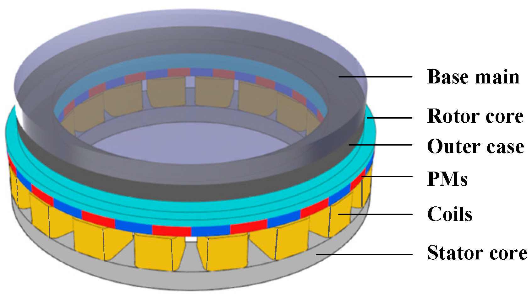
5.1. Robotics Automation and Servo Systems

Robotic applications in industries such as automotive manufacturing and harsh environmental operations require motors that are highly reliable, compact, and offer high torque density. Therefore, PMVMs used for robotics are typically compact in structure, often employing dual-stator or dual-rotor designs, which can improve space utilization and maximize the motor’s torque within limited space. Reference [70] proposed a dual-stator PMVM for robotic grippers, where the dual-stator structure fully utilizes the internal space of the PMVM, resulting in a motor with higher torque density, as shown in Figure 14. Reference [71] designed a high-torque-density PMVM for collaborative robots. Reference [72] introduced a magnetless dual-stator PMVM for robotics applications. Reference [73] introduced a miniature axial flux motor for lens focusing, as shown in Figure 15, and used analytical methods to study its electrical performance.

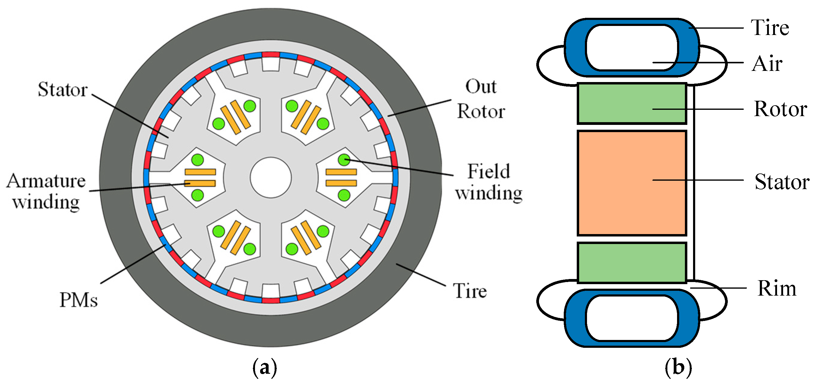
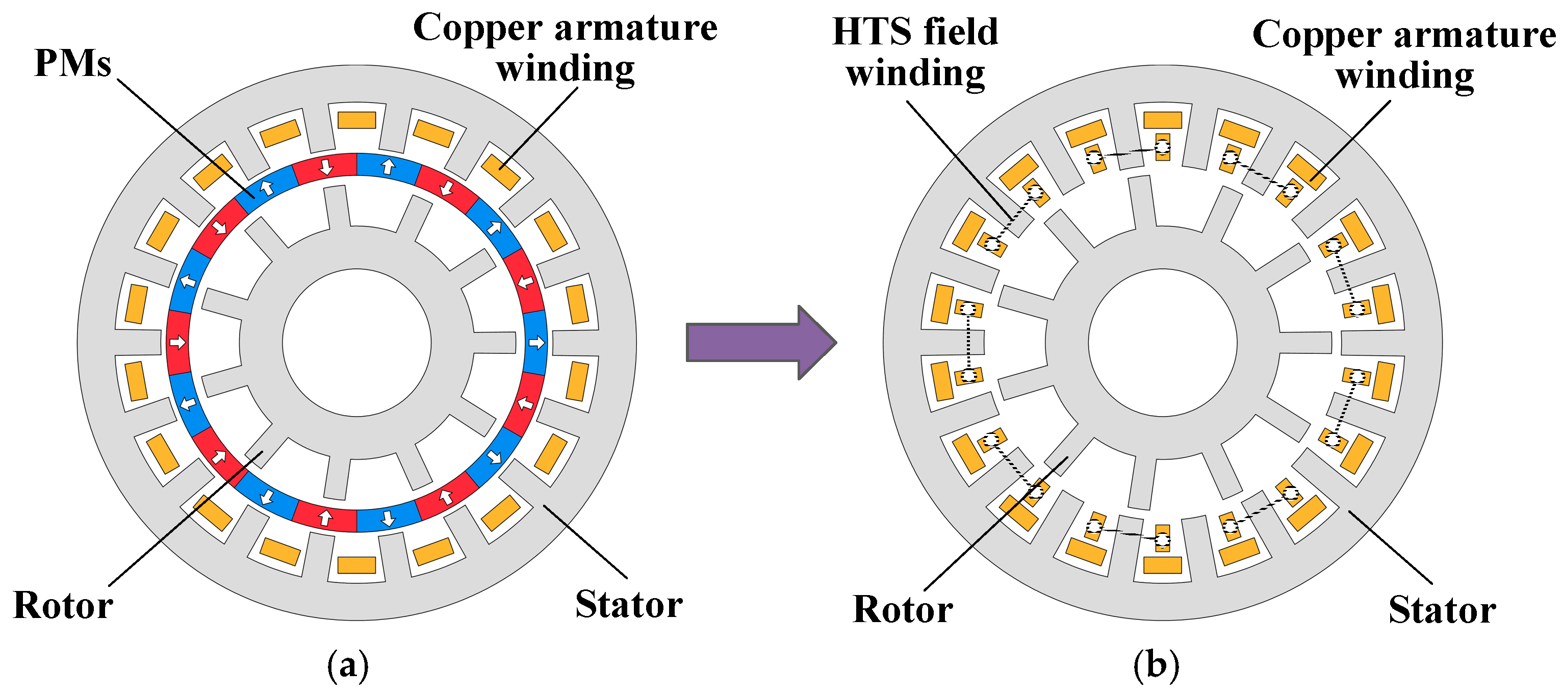
5.2. In-Wheel Drive for Electric Vehicles and Marine Propulsion

The greatest contribution of PMVMs to in-wheel drive systems is their application in direct-drive scenarios. Eliminating the gearbox structure reduces losses and enhances system reliability. Reference [74] proposed a four-port PMVM (FP-PMVM) for hybrid vehicles, combining two PMVMs into one, namely the outer permanent magnet (OPM) and inner permanent magnet (IPM) PMVMs, as shown in Figure 16. The OPM-PMVM provides traction for the rear wheels, while the IMP-PMVM is connected to the internal combustion engine (ICE) through a belt drive system, providing traction for the front wheels. This system replaces two independent motors with a single, robust, and efficient motor, reducing the size of the traction system and lightening the complex mechanical connections. References [75,76] introduced two types of PMVMs for in-wheel direct drive and analyzed their high torque density performance. Axial flux motors, compared to radial flux motors, typically use more permanent magnets, which generally results in higher torque density. In reference [77], Mohammadi et al. proposed an axial flux PMVM for in-wheel drive and compared various permanent magnet configurations in reference [78]. The motor proposed in reference [79] can be used for direct-drive propulsion, while reference [80] introduced a dual-rotor axial flux motor for ship propulsion, optimizing and studying its performance. Reference [81] proposed a dual-stator V-type motor for ship propulsion. In the field of small motors, reference [82] introduced a PMVM for propellers, focusing on the impact of different pole-slot combinations on the performances.

5.3. Wind Power Generation

Reference [83] explored the feasibility of using PMVMs for wind power generation and compared the applications of PMVMs and PMSMs from an economic perspective. It was concluded that PMVMs with a gear ratio less than 5 have significant advantages in wind power generation. Reference [84] designed and fabricated a 5 kW outer rotor PMVM and studied its electromagnetic performance, confirming its advantages for wind power generation. Reference [85] also compared the performance of PMSMs and PMVMs for a 15 kW wind turbine generator, concluding that under the same speed and output power, PMVMs outperform PMSMs in terms of torque performance, operational losses, size, and cost, with the only disadvantage being a lower power factor. References [79,86] studied PMVMs for wind power generation using low-temperature and high-temperature superconducting materials (Figure 17). These motors do not use permanent magnets, and the magnetic field is generated by excitation windings using superconducting materials. Motors using superconducting materials as the excitation source have higher torque density and efficiency compared to permanent magnet motors.

5.4. Limitations of PMVMs in Real-World Scenarios

Despite the significant advantages of PMVMs, such as high torque density and compact size, they still face several challenges and limitations in real-world applications. One major concern is the operational stability of PMVMs under varying conditions, including fluctuations in temperature, load, and supply voltage. Due to their complex magnetic structure and high reliance on precise air-gap modulation, PMVMs may exhibit performance degradation or increased torque ripple when operating outside optimal conditions. Additionally, their adaptability to a wide range of dynamic loads is still under-explored, which limits their applicability in systems with frequently changing mechanical demands. To ensure their robustness and reliability, it is essential to conduct comprehensive evaluations of PMVM performance under diverse operating environments, including start-up, steady-state, and fault conditions. Such studies will help to better understand their behavior and guide the development of control strategies and design improvements suited for practical, large-scale applications.

6. Outlook of Future Development for PMVM

6.1. Air-Gap Field Modulation Theory

As analyzed in Section 3.1, the distribution of air-gap magnetic flux harmonics plays a crucial role in the performance of PMVM. Therefore, the air-gap field modulation theory of PMVM is expected to further develop in order to reveal the intrinsic mechanisms of the magnetic field modulation process and quantitatively calculate the impact of motor parameter characteristics on performance.
Currently, the main approach for precise analysis models of motors is the establishment of an air-gap magnetomotive force-permeability model. However, this method only considers the magnetic field modulation behavior on one side of the air gap and does not account for the overall magnetic circuit changes. With the introduction of modular stators and magnetic barrier rotors, precise analytical models for PMVMs need to be established.

6.2. Multiphysics Coupled Analysis

As a new motor type with great potential for practical applications, the multi-physics coupling analysis of PMVMs is also particularly important. Reference [47] compared the temperature distribution between PMVMs and PMSMs and concluded that for the same size and operating conditions, the temperature of the PMVM is generally higher than that of the PMSM, making temperature analysis for PMVMs particularly important. Currently, the temperature field analysis for PMVMs is limited to motor temperature rise analysis. Further research is needed in areas such as fine thermal models and loss calculation methods.
In terms of dynamic analysis, in-depth studies are required for the calculation of electromagnetic force waves, modal analysis, vibration noise, and unbalanced magnetic pull for PMVMs. Combining magnetic field modulation theory with dynamic research is also a promising direction [87,88].
Due to differences in finite element software algorithms and computational speeds, as well as the large computational load required for 3D-FEA multi-physics coupling analysis, more attention needs to be invested in the multi-physics coupling analysis of PMVMs.

6.3. The Use of Novel Materials

With the development of material science, the use of novel materials can also help improve the performance of PMVMs. References [79,86,89] mentioned that the use of superconducting materials would significantly improve the torque density and efficiency of the motor, making the application of high-temperature and low-temperature superconducting materials a good direction for the development of PMVMs. Regarding stator materials, Reference [56] introduced the use of amorphous magnetic materials as stators for PMVMs and compared the performance of this structure with that of configurations using oriented or non-oriented electrical steel, resulting in a significant reduction in stator iron losses. Reference [90] proposed an axial flux PMVM using soft magnetic composite (SMC) materials for the stator, which has magnetic isotropy and helps to improve the stator’s magnetic concentration effect.

6.4. Predictions and Suggestions

The development of PMVMs holds great promise for advancing technologies in robotics, new energy, and automation, primarily due to their high torque density, precision control, and potential for energy efficiency. The predictions and suggestions on research directions are as follows:
  • In robotics:
    PMVMs can provide the high torque density and precision control required for sophisticated robotic arms, exoskeletons, and mobile robots. A potential innovation in this field could be the development of compact, high-torque actuators that enable robots to perform more complex and precise movements in confined spaces, such as in microsurgical applications or advanced industrial automation. Another breakthrough could involve the integration of PMVMs with artificial intelligence (AI) algorithms to enable real-time adaptive control, allowing robots to autonomously adjust their movements based on environmental feedback, enhancing versatility and precision.
  • In new energy:
    PMVMs can be integral to renewable energy generation systems, such as wind turbines and solar tracking systems. An innovative point could be the development of high-efficiency PMVMs with integrated energy harvesting systems that can optimize energy conversion even under fluctuating conditions. Additionally, advancements in self-healing magnetic materials could increase the durability of PMVMs in harsh environmental conditions, such as those found in offshore wind farms or remote solar installations. A further innovation might be smart grid integration, where PMVMs are used in energy storage systems to improve grid stability and reliability by efficiently adjusting to varying load demands.
  • In automation:
    PMVMs can drive industrial machinery and automated production lines with improved energy efficiency and reduced maintenance costs. A potential innovation in this domain could involve the development of distributed PMVM-based systems that can be easily integrated into modular, flexible manufacturing setups, allowing for highly adaptable and scalable production lines. Another breakthrough could be advanced thermal management systems that enhance the performance and longevity of PMVMs in high-load industrial applications, addressing one of the key challenges in automation. Furthermore, the use of smart sensors and IoT connectivity could enable predictive maintenance, reducing downtime and improving overall operational efficiency.
These innovations, along with advancements in control algorithms, material science, and integration with emerging technologies like AI and IoT, could significantly enhance the adoption and performance of PMVMs across robotics, new energy, and automation industries.

7. Conclusions

The permanent magnet vernier motor (PMVM) is typically used in applications that require high efficiency, high precision, and a small size. Compared to traditional permanent magnet synchronous motors, the main advantages of the PMVM are its higher torque density and lower energy consumption, enabling it to provide stable torque output. The PMVMs show potential in low-speed, high-torque applications and precise control, making them suitable for fields such as precision positioning, automation equipment, and robotics. However, its main challenges are low power factor and relatively poor overload capability, which restrict the PMVM’s application in many industrial scenarios. The complex structure also leads to higher manufacturing costs. Additionally, the performances of PMVM would degrade under certain operating conditions, such as when subjected to high-speed or high-load scenarios, limiting its range of applications. Another drawback is the difficulty in optimizing the motor’s design for various use cases, which can require specialized adjustments for different industries. Generally, with improvements in manufacturing processes and large-scale production, the cost of PMVMs is gradually decreasing, and they are expected to see widespread use in more fields in the future. Future research could focus on improving the power factor and expanding the operational range of PMVMs, as well as exploring new materials and design strategies to further enhance their performance and cost-effectiveness.

Author Contributions

Motor type classification, G.Z. and X.G.; data collection, X.G.; analysis by airgap field modulation theory, X.G. and J.Z.; summarization on applications, G.Z., X.G., and W.H.; optimization methods, G.Z. and X.G.; supervision, G.Z. and W.H.; writing—original draft, G.Z. and X.G.; writing—manuscript editing, W.H. All authors have read and agreed to the published version of the manuscript.

Funding

This work is supported in part by the National Nature Science Foundation of China under Grant 52477038, in part by the Open Fund of Laboratory of Aerospace Servo Actuation and Transmission under Grant LASAT-2022-A01-01.

Institutional Review Board Statement

Not applicable.

Informed Consent Statement

Not applicable.

Data Availability Statement

Not applicable.

Conflicts of Interest

The authors declare no conflicts of interest.

References

  1. Sankhwar, P. Application of permanent magnet synchronous motor for electric vehicle. Indian J. Des. Eng. 2024, 4, 1–6. [Google Scholar] [CrossRef]
  2. Shen, J.; Wang, X.; Zhang, Z.; Ren, S.; Ma, D.; Xiao, D. Research on the application of dual three-phase PMSM in renewable energy system. In Proceedings of the 2023 26th International Conference on Electrical Machines and Systems (ICEMS), Zhuhai, China, 5–8 November 2023; pp. 3475–3479. [Google Scholar]
  3. Kashif, M.; Singh, B. Design and geometric optimization of spoke-type PMSM for solar PV based water pump. In Proceedings of the 2020 IEEE 7th Uttar Pradesh Section International Conference on Electrical, Electronics and Computer Engineering (UPCON), Prayagraj, India, 27–29 November 2020; pp. 1–6. [Google Scholar]
  4. Fu, W.N.; Ho, S.L. A quantitative comparative analysis of a novel flux-modulated permanent-magnet motor for low-speed drive. IEEE Trans. Magn. 2010, 46, 127–134. [Google Scholar] [CrossRef]
  5. Lee, C.H. Vernier motor and its design. IEEE Trans. Power App. Syst. 1963, 82, 343–349. [Google Scholar] [CrossRef]
  6. Rhodes, D.J. Assessment of vernier motor design using generalized machine concepts. IEEE Trans. Power App. Syst. 1977, 96, 1346–1352. [Google Scholar] [CrossRef]
  7. Ishizaki, A.; Tanaka, T.; Takasaki, K.; Nishikata, S. Theory and optimum design of PM Vernier motor. In Proceedings of the 1995 Seventh International Conference on Electrical Machines and Drives, Durham, UK, 11–13 September 1995; pp. 208–212. [Google Scholar]
  8. Toba, A.; Lipo, T.A. Novel dual-excitation permanent magnet Vernier machine. In Proceedings of the Conference Record of the 1999 IEEE Industry Applications Conference, Phoenix, AZ, USA, 3–7 October 1999; pp. 2539–2544. [Google Scholar]
  9. Atallah, K.; Howe, D. A novel high-performance magnetic gear. IEEE Trans. Magn. 2001, 37, 2844–2846. [Google Scholar] [CrossRef]
  10. Rasmussen, P.O.; Andersen, T.O.; Jorgensen, F.T.; Nielsen, O. Development of a high-performance magnetic gear. IEEE Trans. Ind. Appl. 2005, 41, 764–770. [Google Scholar] [CrossRef]
  11. Li, X.; Chau, K.T.; Cheng, M.; Hua, W.; Du, Y. An improved coaxial magnetic gear using flux focusing. In Proceedings of the 2011 International Conference on Electrical Machines and Systems, Beijing, China, 20–23 August 2011; pp. 1–4. [Google Scholar]
  12. Uppalapati, K.K.; Bomela, W.B.; Bird, J.Z.; Calvin, M.D.; Wright, J.D. Experimental evaluation of low-speed flux-focusing magnetic gearboxes. IEEE Trans. Ind. Appl. 2014, 50, 3637–3643. [Google Scholar] [CrossRef]
  13. Yin, X.; Pfister, P.-D.; Fang, Y. A novel magnetic gear: Toward a higher torque density. IEEE Trans. Magn. 2015, 51, 1–4. [Google Scholar] [CrossRef]
  14. Atallah, K.; Calverley, S.D.; Howe, D. Design, analysis and realization of a high-performance magnetic gear. IEE Proc.-Electr. Power Appl. 2004, 151, 135–143. [Google Scholar] [CrossRef]
  15. Toba, A.; Lipo, T.A. Generic torque-maximizing design methodology of surface permanent-magnet vernier machine. IEEE Trans. Ind. Appl. 2000, 36, 1539–1546. [Google Scholar]
  16. Cheng, M.; Han, P.; Du, Y.; Wen, H.; Li, X. A general air gap field modulation theory for electrical machines. IEEE J. Emerg. Sel. Top. Power Electron. 2022, 10, 1712–1732. [Google Scholar] [CrossRef]
  17. Xu, G.; Jian, L.; Gong, W.; Zhao, W. Quantitative comparison of flux-modulated interior permanent magnet machines with distributed windings and concentrated windings. Prog. Electromagn. Res. 2012, 129, 109–123. [Google Scholar] [CrossRef]
  18. Qu, R.; Li, D.; Wang, J. Relationship between magnetic gears and vernier machines. In Proceedings of the 2011 International Conference on Electrical Machines and Systems, Beijing, China, 20–23 August 2011; pp. 1–6. [Google Scholar]
  19. Zou, T.; Li, D.; Qu, R.; Jiang, D.; Li, J. Advanced high torque density PM vernier machine with multiple working harmonics. IEEE Trans. Ind. Appl. 2017, 53, 5295–5304. [Google Scholar] [CrossRef]
  20. Chung, S.-U.; Kim, J.-W.; Woo, B.-C.; Hong, D.-K.; Lee, J.-Y.; Koo, D.-H. A novel design of modular three-phase permanent magnet vernier machine with consequent pole rotor. IEEE Trans. Magn. 2011, 47, 4215–4218. [Google Scholar] [CrossRef]
  21. Cheng, M.; Han, P.; Hua, W. General airgap field modulation theory for electrical machines. IEEE Trans. Ind. Electron. 2017, 64, 6063–6074. [Google Scholar] [CrossRef]
  22. Cheng, M.; Wen, H.; Han, P.; Zhu, X. Analysis of airgap field modulation principle of simple salient poles. IEEE Trans. Ind. Electron. 2019, 66, 2628–2638. [Google Scholar] [CrossRef]
  23. Yu, Y.; Chai, F.; Pei, Y.; Chen, L. Comparisons of torque performance in surface-mounted PM vernier machines with different stator tooth topologies. IEEE Trans. Ind. Appl. 2019, 55, 3671–3684. [Google Scholar] [CrossRef]
  24. Zou, T.; Qu, R.; Li, J.; Li, D. Analysis and design of a dual-rotor axial-flux vernier permanent magnet machine. In Proceedings of the 2015 IEEE Energy Conversion Congress and Exposition (ECCE), Montreal, QC, Canada, 20–24 September 2015; pp. 3906–3913. [Google Scholar]
  25. Allahyari, A.; Torkaman, H. A novel high-performance consequent pole dual rotor permanent magnet vernier machine. IEEE Trans. Energy Convers. 2020, 35, 1238–1246. [Google Scholar] [CrossRef]
  26. Zhao, F.; Lipo, T.A.; Kwon, B.-I. A novel dual-stator axial-flux spoke-type permanent magnet vernier machine for direct-drive applications. IEEE Trans. Magn. 2014, 50, 1–4. [Google Scholar] [CrossRef]
  27. Kwon, J.-W.; Kwon, B.-I. Investigation of dual-stator spoke-type vernier machine for EV application. IEEE Trans. Magn. 2018, 54, 8206505. [Google Scholar] [CrossRef]
  28. Kim, B.; Lipo, T.A. Design of a surface PM vernier motor for a practical variable speed application. In Proceedings of the 2015 IEEE Energy Conversion Congress and Exposition (ECCE), Montreal, QC, Canada, 20–24 September 2015; pp. 776–783. [Google Scholar]
  29. Yu, Y.; Chai, F.; Pei, Y.; Zhu, J.; Xie, S.; Cao, L.; Lee, C.H.T. Investigation of a novel phase-unit axial-modular permanent magnet vernier machine with integral-slot non-overlapping concentrated windings. IEEE Trans. Ind. Appl. 2024, 60, 6144–6157. [Google Scholar] [CrossRef]
  30. Li, D.; Qu, R.; Xu, W.; Li, J.; Lipo, T.A. Design process of dual-stator, spoke-array vernier permanent magnet machines. In Proceedings of the 2014 IEEE Energy Conversion Congress and Exposition (ECCE), Pittsburgh, PA, USA, 14–18 September 2014; pp. 2350–2357. [Google Scholar]
  31. Yu, Y.; Chai, F.; Pei, Y.; Doppelbauer, M. Investigation of PM loss in spoke-type permanent magnet vernier motors with different stator topologies for in-wheel direct drive. IEEE Trans. Ind. Appl. 2022, 58, 4562–4574. [Google Scholar] [CrossRef]
  32. Jing, L.; Kui, Z.; Yang, K.; Min, Z. Characteristic analysis and optimization of U-PM vernier machine with alternating flux bridge. J. Electr. Eng. Technol. 2023, 18, 281–290. [Google Scholar] [CrossRef]
  33. Li, Y.; Jing, L. Analysis and optimization of a novel dual PM vernier machine with Halbach array. J. Electr. Eng. Technol. 2023, 18, 4159–4167. [Google Scholar] [CrossRef]
  34. Li, Y.; Jing, L. Design and research of novel consequent-pole dual PM vernier machines with spoke and Halbach array. J. Electr. Eng. Technol. 2024, 19, 2987–2994. [Google Scholar] [CrossRef]
  35. Kataoka, Y.; Takayama, M.; Matsushima, Y.; Anazawa, Y. Design of surface permanent magnet-type vernier motor. In Proceedings of the 2012 15th International Conference on Electrical Machines and Systems (ICEMS), Sapporo, Japan, 21–24 October 2012; pp. 1–6. [Google Scholar]
  36. Wei, L.; Nakamura, T. A novel dual-stator hybrid excited permanent magnet vernier machine with Halbach-array PMs. IEEE Trans. Magn. 2021, 57, 1–5. [Google Scholar] [CrossRef]
  37. Chen, Y.; Zhu, X.; Quan, L.; Xiang, Z.; Du, Y.; Bu, X. A V-shaped PM vernier motor with enhanced flux-modulated effect and low torque ripple. IEEE Trans. Magn. 2018, 54, 1–4. [Google Scholar] [CrossRef]
  38. Shen, F.; Yan, Y.; Shih Onn, B.C.; Gajanayake, C.J.; Wang, S.; Lee, C.H.T. Analysis of a vernier machine with spoke-V array permanent magnets. In Proceedings of the IECON 2022—48th Annual Conference of the IEEE Industrial Electronics Society, Brussels, Belgium, 17–20 October 2022; pp. 1–6. [Google Scholar]
  39. Zhao, W.; Sun, X.; Ji, J.; Liu, G. Design and analysis of new vernier permanent-magnet machine with improved torque capability. IEEE Trans. Appl. Supercond. 2016, 26, 5201505. [Google Scholar] [CrossRef]
  40. Li, D.; Cao, Y.; Wang, B. Analysis and design of a new type of polymer-magnet permanent magnet fault-tolerant vernier motor. In Proceedings of the 2024 IEEE 7th International Electrical and Energy Conference (CIEEC), Harbin, China, 10–12 May 2024; pp. 4517–4522. [Google Scholar]
  41. Zou, T.; Li, D.; Qu, R.; Li, J.; Jiang, D. Analysis of a dual-rotor, toroidal-winding, axial-flux vernier permanent magnet machine. IEEE Trans. Ind. Appl. 2017, 53, 1920–1930. [Google Scholar] [CrossRef]
  42. Ahmad, I.; Ikram, J.; Yousuf, M.; Badar, R.; Bukhari, S.S.H.; Ro, J. Performance improvement of multi-rotor axial flux vernier permanent magnet machine by permanent magnet shaping. IEEE Access 2021, 9, 143188–143197. [Google Scholar] [CrossRef]
  43. He, Z.; Xiao, F.; Du, Y.; Zhu, X. Comparison of permanent magnet vernier motors with evenly and unevenly distributed modulation teeth. IEEE Trans. Magn. 2023, 59, 1–5. [Google Scholar] [CrossRef]
  44. Park, J.H.; Lukman, G.F.; Kang, D.; Ahn, J.-W. Optimization of non-uniform flux modulation poles of a dual-stator permanent magnet vernier machine for performance improvement. J. Electr. Eng. Technol. 2022, 17, 2203–2211. [Google Scholar] [CrossRef]
  45. Yang, G.; Li, J.; Lin, M. Design and analysis of novel modular stator axial-flux permanent magnet vernier machine with improved power factor. IEEE Access 2023, 11, 108580–108590. [Google Scholar] [CrossRef]
  46. Fang, L.; Li, D.; Ren, X.; Qu, R. A novel permanent magnet vernier machine with coding-shaped tooth. IEEE Trans. Ind. Electron. 2022, 69, 6058–6068. [Google Scholar] [CrossRef]
  47. Yanlei, Y.; Feng, C.; Yulong, P.; Xi, Z.; Lee, C.H.T. Comparative study of thermal characteristic in permanent magnet synchronous machine and vernier machine for in-wheel drive. In Proceedings of the 2023 26th International Conference on Electrical Machines and Systems (ICEMS), Zhuhai, China, 5–8 November 2023; pp. 1218–1222. [Google Scholar]
  48. Liu, Y.; Li, H.Y.; Zhu, Z.Q. A high-power factor vernier machine with coil pitch of two slot pitches. IEEE Trans. Magn. 2018, 54, 8206505. [Google Scholar] [CrossRef]
  49. Wu, L.; Qu, R. A novel dual-stator vernier permanent magnet machine with improved power factor. IEEE Trans. Ind. Appl. 2022, 58, 3486–3496. [Google Scholar] [CrossRef]
  50. Jia, S.; Qu, R.; Li, J.; Li, D.; Fang, H. Hybrid excited vernier PM machines with novel DC-biased sinusoidal armature current. In Proceedings of the 2016 IEEE Energy Conversion Congress and Exposition (ECCE), Milwaukee, WI, USA, 18–22 September 2016; pp. 1–8. [Google Scholar]
  51. Thyroff, D.; Hahn, I. Optimization of the flux modulation poles for vernier machines with concentrated windings. In Proceedings of the 2017 IEEE Workshop on Electrical Machines Design, Control and Diagnosis (WEMDCD), Nottingham, UK, 20–21 April 2017; pp. 113–118. [Google Scholar]
  52. Thyroff, D.; Hittinger, C.; Hahn, I. Analytic power factor calculation for vernier machines with concentrated windings. In Proceedings of the 2017 IEEE International Electric Machines and Drives Conference (IEMDC), Miami, FL, USA, 21–24 May 2017; pp. 1–6. [Google Scholar]
  53. Kim, S.-J.; Kim, C.-H.; Jung, S.-Y.; Kim, Y.-J. Optimal design of novel pole piece for power density improvement of magnetic gear using polynomial regression analysis. IEEE Trans. Energy Convers. 2015, 30, 1171–1179. [Google Scholar] [CrossRef]
  54. Nakagawa, H.; Sato, T.; Todaka, T. Development of a new stator module type vernier motor utilizing amorphous cut core. In Proceedings of the 2018 IEEE International Magnetics Conference (INTERMAG), Singapore, 23–27 April 2018; pp. 1–5. [Google Scholar]
  55. Zhao, Y.; Ren, X.; Fan, X.; Li, D.; Qu, R. A high power factor permanent magnet vernier machine with modular stator and yokeless rotor. IEEE Trans. Ind. Electron. 2023, 70, 7141–7152. [Google Scholar] [CrossRef]
  56. Xiang, Z.; Gui, S.; Zhu, X.; Wei, J.; Quan, L.; Chen, K. Design and analysis of a high torque performance dual-side PM vernier motor with synergetic modulation enhancement. IEEE Trans. Magn. 2024, 60, 8204807. [Google Scholar] [CrossRef]
  57. Wang, T.; Zhu, X.; Xiang, Z.; Fan, D.; Quan, L. Torque ripple suppression of a permanent magnet vernier motor from perspective of shifted air-gap permeance distribution. IEEE Trans. Magn. 2022, 58, 8203006. [Google Scholar] [CrossRef]
  58. Xiang, Z.; Wei, J.; Zhu, X. Torque ripple suppression of a PM vernier machine from perspective of time and space harmonic magnetic field. IEEE Trans. Ind. Electron. 2024, 71, 10150–10161. [Google Scholar] [CrossRef]
  59. Cetin, E.; Daldaban, F. Analyzing the profile effects of the various magnet shapes in axial flux PM motors by means of 3D-FEA. Electronics 2018, 7, 13. [Google Scholar] [CrossRef]
  60. Yousuf, M.; Khan, F.; Ikram, J.; Badar, R.; Bukhari, S.S.H.; Ro, J. Reduction of torque ripples in multi-stack slotless axial flux machine by using right angled trapezoidal permanent magnet. IEEE Access 2021, 9, 22760–22773. [Google Scholar] [CrossRef]
  61. Fan, Y.; Mei, Y.; Zhang, Q. Torque ripple reduction of outer rotor permanent magnet vernier machine with concentrated winding. In Proceedings of the 2020 International Conference on Electrical Machines (ICEM), Gothenburg, Sweden, 23–26 August 2020; pp. 543–549. [Google Scholar]
  62. Li, R.; Shi, C.; Qu, R.; Li, D.; Ren, X.; Fedida, V.; Zhou, Y. A novel modular stator fractional pole-pair permanent-magnet vernier machine with low torque ripple for servo applications. IEEE Trans. Magn. 2021, 57, 8102406. [Google Scholar] [CrossRef]
  63. Chen, Z.; Wang, J.; Hu, Z.; Xiao, J.; Zhou, L.; Wang, H. Design of consequent pole permanent magnet vernier motor for downhole electric drilling system. In Proceedings of the 2021 IEEE 4th Student Conference on Electric Machines and Systems (SCEMS), Huzhou, China, 1–3 December 2021; pp. 1–6. [Google Scholar]
  64. Siddiqi, M.R.; Humza, M.; Yazdan, T.; Hur, J. Cost-effective design of dual airgap permanent magnet vernier machine having a yokeless consequent pole rotor. IEEE Access 2024, 12, 108224–108232. [Google Scholar] [CrossRef]
  65. Baloch, N.; Kwon, B.-I.; Gao, Y. Low-cost high-torque-density dual-stator consequent-pole permanent magnet vernier machine. IEEE Trans. Magn. 2018, 54, 8206105. [Google Scholar] [CrossRef]
  66. Kang, M.; Xu, L.; Ji, J.H.; Zhu, X.H. Design and analysis of a high torque density hybrid permanent magnet excited vernier machine. Energies 2022, 15, 1723. [Google Scholar] [CrossRef]
  67. Rehman, A.; Kim, B. Characteristics analysis of consequent-pole ferrite magnet vernier machine using novel equivalent magnetic circuit. IEEE J. Emerg. Sel. Top. Power Electron. 2022, 10, 1823–1833. [Google Scholar] [CrossRef]
  68. Gong, C.; Deng, F. Demagnetization analysis of a split-tooth concentrated-winding vernier machine using Halbach-array-based ferrite magnets. In Proceedings of the 2021 IEEE International Electric Machines & Drives Conference (IEMDC), Hartford, CT, USA, 17–20 May 2021; pp. 1–6. [Google Scholar]
  69. Lee, C.H.T.; Chau, K.T.; Liu, C. Design and analysis of an electronic-geared magnetless machine for electric vehicles. IEEE Trans. Ind. Electron. 2016, 63, 6705–6714. [Google Scholar] [CrossRef]
  70. Woo, H.; Kang, D.; Oh, Y.; Park, G.-S. Design and characteristics analysis of double air-gap vernier motor with high torque for robot gripper. In Proceedings of the 2023 26th International Conference on Electrical Machines and Systems (ICEMS), Zhuhai, China, 5–8 November 2023; pp. 2921–2925. [Google Scholar]
  71. Duong, M.-T.; Luu, T.-P.; Do, T.D.; Perriard, Y. Design of high torque density permanent magnet motors and drives for collaborative robot applications. In Proceedings of the 2021 24th International Conference on Electrical Machines and Systems (ICEMS), Gyeongju, Republic of Korea, 31 October 2021–3 November 2021. [Google Scholar]
  72. Yu, J.; Liu, C. Design of a double-stator magnetless vernier machine for direct-drive robotics. IEEE Trans. Magn. 2018, 54, 8105805. [Google Scholar] [CrossRef]
  73. Zhao, F.; Kim, M.-S.; Kwon, B.-I.; Baek, J.-H. A small axial-flux vernier machine with ring-type magnets for the auto-focusing lens drive system. IEEE Trans. Magn. 2016, 52, 1–4. [Google Scholar] [CrossRef]
  74. Muteba, M. Performance evaluation of a four-port PM vernier motor for hybrid electric vehicles. In Proceedings of the 2020 IEEE 29th International Symposium on Industrial Electronics (ISIE), Delft, The Netherlands, 17–19 June 2020; pp. 345–350. [Google Scholar]
  75. Liu, C. Design of a new outer-rotor flux-controllable vernier PM in-wheel motor drive for electric vehicle. In Proceedings of the 2011 International Conference on Electrical Machines and Systems, Beijing, China, 20–23 August 2011; pp. 1–6. [Google Scholar]
  76. Pei, Y.; Yu, Y.; Chai, F.; Yu, Y. Design and comparative analysis of a novel PM vernier motor with trapezoidal magnets and flux barriers for in-wheel traction application. In Proceedings of the 2019 22nd International Conference on Electrical Machines and Systems (ICEMS), Harbin, China, 11–14 August 2019; pp. 1–6. [Google Scholar]
  77. Mohammadi, A.; Chulaee, Y.; Cramer, A.M.; Boldea, I.; Ionel, D.M. Axial flux permanent magnet vernier machine with single-wound dual-stator and spoke permanent magnet rotor for electric vehicle in-wheel traction. In Proceedings of the 2023 IEEE Transportation Electrification Conference & Expo (ITEC), Detroit, MI, USA, 21–23 June 2023; pp. 1–5. [Google Scholar]
  78. Mohammadi, A.; Cramer, A.M.; Ionel, D.M. Comparative analysis of vernier machines with spoke, surface mounted, and Halbach PM rotors for in-wheel traction. In Proceedings of the 2024 IEEE Transportation Electrification Conference and Expo (ITEC), Chicago, IL, USA, 19–21 June 2024; pp. 1–6. [Google Scholar]
  79. Xu, L.; Liu, G.; Zhao, W.; Ji, J. Stator-excited vernier high-temperature superconducting machine for direct drive propulsion. IEEE Trans. Appl. Supercond. 2016, 26, 5207505. [Google Scholar] [CrossRef]
  80. Yu, Y.; Chai, F.; Pei, Y.; Lee, C.H.T. A novel axial-flux permanent magnet vernier machine with H-core stator modules and toroidal windings for electric aircraft propulsion system. In Proceedings of the 2024 IEEE Transportation Electrification Conference and Expo, Asia-Pacific (ITEC Asia-Pacific), Xi’an, China, 10–13 October 2024; pp. 712–717. [Google Scholar]
  81. Yu, J.; Mi, W.; Cai, Z.; Song, Z.; Liu, S.; Liu, C. Design principle considering structural mutual effects of double-stator V-shape-PM vernier machines for electric ship propulsion. IEEE Trans. Transp. Electrif. 2024, 10, 496–508. [Google Scholar] [CrossRef]
  82. Cai, Y.; Zhu, J.; Liu, Q. Slot-pole combination and optimization of a flux-concentrating fault-tolerant permanent magnet vernier rim-driven motor. In Proceedings of the 2024 IEEE 7th International Electrical and Energy Conference (CIEEC), Harbin, China, 10–12 May 2024; pp. 1830–1835. [Google Scholar]
  83. Tlali, P.M.; Wang, R.-J. PM vernier machine for utility scale wind generator applications: Design and evaluation. In Proceedings of the 2020 International Conference on Electrical Machines (ICEM), Gothenburg, Sweden, 23–26 August 2020; pp. 2637–2643. [Google Scholar]
  84. Li, X.; Chau, K.T.; Cheng, M. Analysis, design and experimental verification of a field-modulated permanent-magnet machine for direct-drive wind turbines. IET Electr. Power Appl. 2015, 9, 150–159. [Google Scholar] [CrossRef]
  85. Tlali, P.M.; Wang, R.-J.; Gerber, S. Comparison of PM vernier and conventional synchronous 15 kW wind generators. In Proceedings of the 2018 XIII International Conference on Electrical Machines (ICEM), Alexandroupoli, Greece, 3–6 September 2018; pp. 2065–2071. [Google Scholar]
  86. Gao, Y.; Qu, R.; Li, D.; Li, J.; Zhou, G. Design of a dual-stator LTS vernier machine for direct-drive wind power generation. IEEE Trans. Appl. Supercond. 2016, 26, 5204505. [Google Scholar] [CrossRef]
  87. Mao, Y.; Zhao, W.; Zhu, S.; Chen, Q.; Ji, J. Vibration investigation of spoke-type PM machine with asymmetric rotor considering modulation effect of stator teeth. IEEE Trans. Ind. Electron. 2021, 68, 9092–9103. [Google Scholar] [CrossRef]
  88. Zhu, S.; Zhao, W.; Ji, J.; Liu, G.; Mao, Y.; Liu, T. Investigation of bread-loaf magnet on vibration performance in FSCW PMSM considering force modulation effect. IEEE Trans. Transp. Electrif. 2021, 7, 1379–1389. [Google Scholar] [CrossRef]
  89. Li, W.; Ching, T.W.; Chau, K.T.; Lee, C.H.T. A superconducting vernier motor for electric ship propulsion. IEEE Trans. Appl. Supercond. 2018, 28, 1–6. [Google Scholar] [CrossRef]
  90. Liu, C.; Wang, K.; Wang, S.; Niu, F.; Wang, Y. Analysis and design optimization of a low-cost axial flux vernier machine with SMC cores and ferrite magnets. Electr. Eng. 2020, 102, 2595–2604. [Google Scholar] [CrossRef]
Figure 1. Two typical PMVM stator topologies. (a) Open slot stator; (b) Split-tooth stator.
Energies 18 02353 g001
Figure 2. Evolution from magnetic gears to open-slot PMVM.
Energies 18 02353 g002
Figure 3. Evolution from magnetic gears to split-tooth PMVM.
Energies 18 02353 g003
Figure 4. Two typical PMVM stator topologies. (a) Modulation process of magnetic-motive-force (MMF); (b) Spectrum of the original MMF and modulated MMF.
Energies 18 02353 g004
Figure 5. Typical topologies and key performances of PMVM.
Energies 18 02353 g005
Figure 6. Typical PMVMs with axial flux and toroidal winding. (a) Dual stator; (b) Dual rotor.
Energies 18 02353 g006
Figure 7. Typical PMVMs with radial flux and toroidal winding. (a) Open-slot stator; (b) Split-tooth stator and toroidal/drum winding.
Energies 18 02353 g007
Figure 8. The typical PM types of PMVM. (a) Surface-mounted PM; (b) Spoke-type PM; (c) Halbach PM; and (d) V-shape PM.
Energies 18 02353 g008
Figure 9. PMVM with two sets of PMs.
Energies 18 02353 g009
Figure 10. Dual-stator flux concentrated PMVM.
Energies 18 02353 g010
Figure 11. PMVMs with special design on stator teeth. (a) Non-uniformly distributed teeth; (b) Unequal split teeth; (c) Coded stator tooth.
Energies 18 02353 g011
Figure 12. Two typical PMVM stator topologies. (a) Consequent-pole dual-side PMVM; (b) Shifted permeance design of stator tooth.
Energies 18 02353 g012
Figure 13. 3-D irregular PM shapes.
Energies 18 02353 g013
Figure 14. Double air gap PM used in a robot gripper.
Energies 18 02353 g014
Figure 15. Axial-flux PMVM with ring-type PM used in the auto-focusing lens drive system.
Energies 18 02353 g015
Figure 16. Flux-controllable in-wheel drive PMVM for electric vehicles. (a) PMVM topology; (b) Schematic topologies of in-wheel motor drives.
Energies 18 02353 g016
Figure 17. Evolution from PMVM to high-temperature superconductor vernier motor. (a) PMVM; (b) High-temperature superconductor vernier motor.
Energies 18 02353 g017
Table 1. Comprehensive comparison of the typical PM motors.
CharacteristicsPermanent Magnet Vernier Motor (PMVM)Brushless DC Motor (BLDC)Permanent Magnet Synchronous Motor (PMSM)PM Assistant Synchronous Reluctance Motor
(PMaSynRM)
EfficiencyHighHighHighMedium
Torque densityHighLowHighMedium to high
Power factorLowHighHighMedium to high
Suitable conditionLow-speed, High-torqueHigh-speed, Low-torquePrecision controlHigh-speed, Low-torque
Control methodPrecision controlSimple, suitable for high-speed applicationsPrecision controlComplex control strategy
CostHigh
Complex structure
Low
Mature technology
Medium to High
Rare-earth PM material
Medium
Complex control system
ApplicationsPrecision positioning, automation, roboticsHigh-speed power tools, electric vehicles, home appliancesHigh-precision servos, industrial automation, roboticsElectric vehicles, wind power generation
DisadvantagesComplex structure, low power factor, high manufacturing costPoor adaptability, performance instability with load changesHigh cost, complex design and controlHigh control requirements, complex design, difficult startup
Future research directionsImprove power factor, expand operational range, reduce costImprove control precision, increase load adaptabilityEnhance feasibility for high-power applications, optimize control strategiesImprove control precision, reduce torque ripple, and adapt to more application fields
Disclaimer/Publisher’s Note: The statements, opinions and data contained in all publications are solely those of the individual author(s) and contributor(s) and not of MDPI and/or the editor(s). MDPI and/or the editor(s) disclaim responsibility for any injury to people or property resulting from any ideas, methods, instructions or products referred to in the content.

