Abstract
This paper encapsulates the advancements in marine renewables utilization technologies globally, analyzed through the lenses of research emphasis and variations in device mechanisms. The multi-energy complementarity and the integration of marine renewable energy systems with aquaculture technologies are discussed, and the engineering applications are introduced. Tidal energy and offshore wind energy technologies have achieved mature commercial operation, while tidal current energy and wave energy technologies are undergoing full-scale prototype testing. Temperature-difference energy technology has reached the full-scale prototype testing phase, whereas salinity-gradient energy technology remains in the laboratory verification stage. In recent years, many researchers have conducted engineering measurements, and further breakthroughs are needed in critical enabling technologies and safety measures. From the standpoint of geographical integration, the realization of aquaculture with offshore wind energy and wave energy or tidal current energy is simpler. The integration of aquaculture with marine renewable energy technologies represents a promising avenue for the future development and global utilization of marine energy resources.
1. Overview of Marine Renewable Energy
About 71% of the surface area of the globe is ocean, which is rich not only in oil and aquatic resources, but also in a great volume of renewable energy, including salinity-gradient energy, temperature-difference energy, tidal current energy, wind energy, wave energy, etc., as shown in Figure 1.
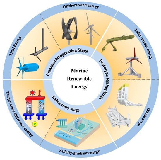
Figure 1.
Classification of marine renewable energy.
Offshore wind energy [1] resources have 20–40% higher energy efficiency than land-based wind farms. Its benefits also include low land occupation, strong wind speed, reduced dust, great power, consistent operation, and zero dust emissions. At the same time, it can reduce wear on wind turbines and extend their service life, making it suitable for large-scale development. Tidal energy [2] is derived from the regular fluctuations of saltwater, which represents the most consistent kind of seawater motion, and has been acknowledged and harnessed by humans since ancient times. Tidal power generation necessitates the utilization of advantageous topography, such as bays and estuaries, to construct water embankments and reservoirs for the accumulation of substantial saltwater for power generation [3]. Wave energy [4,5] is the kinetic and potential energy of ocean surface waves generated by wind, representing the most volatile kind of marine renewable energy. Tidal current energy [6] pertains to the kinetic energy generated by tidal flow, primarily associated with the energy produced by the periodic oscillations of seawater on the Earth’s surface, resulting from the gravitational influence of celestial bodies such as the moon and the sun. This energy varies in magnitude and direction approximately twice daily in accordance with tidal fluctuations. In comparison to wave energy, the fluctuation of tidal current energy is more constant and consistent. Certain researchers assert that locations exhibiting peak velocities over 2 m/s are conducive to the development of tidal current energy [7].
Temperature-difference energy and salinity-gradient energy are also important forms of marine renewable energy and have shown potential in specific application scenarios [8]. Temperature-difference energy [9,10] pertains to the disparity in temperature between surface seawater and deep seawater, which can be harnessed to facilitate a thermal cycle and produce power. Salinity-gradient energy [11] denotes the energy derived from the chemical potential difference between seawater and freshwater, or between two types of seawater with varying salt concentrations, primarily occurring at the interface of rivers and oceans. Research on salinity-gradient energy remains primarily at the laboratory stage, with significant progress required before practical application can be realized [8].
Recently, the cooperation between marine renewable energy and aquaculture has shown great potential in cost sharing and social benefits [12]. The integration of aquaculture with standalone marine renewable energy is easier to achieve and has been explored in engineering. The viability of combining aquaculture with offshore wind energy has been demonstrated recently [12,13]. Wave energy utilization for power generation can deliver clean and high-quality electricity to offshore islands, aquaculture operations, and offshore development platforms [14,15,16]. The integration of aquaculture with multiple energy sources needs to overcome enormous challenges, and many attempts are still at the conceptual stage. Currently, researchers mainly focus on the integration of aquaculture with relatively mature forms of energy, such as solar, offshore wind, wave, tidal, and tidal current energy. Some concepts have been proposed, such as offshore wind–wave–aquaculture [17], offshore wind–tidal current–aquaculture, etc.
This paper presents the advancements in marine renewable energy utilization technologies, analyzed through the lenses of global research focus and engineering applications. Based on this, the integration of aquaculture with single and multiple energy sources is discussed. This work provides references for the advancement and synergistic usage of marine resources.
2. Existing Technology in Marine Renewable Energy Conversion
The primary technological pathways and standard development methods of marine renewable energy encompass offshore wind energy, tidal power, wave energy, tidal current power, temperature-difference energy, and salinity-gradient energy, among others.
2.1. Offshore Wind Energy
Offshore wind energy provides the power supply for power consumption centers in coastal areas. The large wind turbine and floating wind turbine, which need fewer stands in the wind farm, are helpful for reducing tower foundation costs in the construction process of the wind farm [18]. Meanwhile, due to the reduction of the number of units, the maintenance cost can be reduced in the subsequent operation process. The two forms of existing wind turbines are horizontal and vertical axis ones [19], as shown in Figure 2.
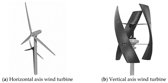
Figure 2.
Horizontal and vertical axis wind turbines [19].
The advantages of offshore wind turbines are as follows [20,21,22].
(a) Resources related to offshore wind energy abound. About one fifth greater than the onshore wind speed is the offshore wind speed 10 km away from the coast. The wind speed increases the further one moves away from the coast [23].
(b) The sea space is continuous and vast, and the development space is less limited. Offshore wind turbines can be installed far from the coast, can be free from the size restrictions of highway and railway transport, and can avoid noise and visual pollution.
(c) There are fewer interferences at sea, including less wind shear, less turbulence, less friction, and less force, and the wind is more durable and stable.
Table 1 compares the technological levels, conversion efficiency, and scales of horizontal and vertical axis wind turbines.

Table 1.
Comparison of horizontal and vertical axis wind turbines.
2.2. Tidal Energy
Since the tidal power station uses ports or bays to enclose reservoirs and exploit energy by tidal oscillations, its effects on the surroundings are minor. Less influenced by rainy and dry seasons, the tidal energy is a rather constant and dependable source of energy [30]. On the contrary, aquaculture, transportation, and other comprehensive utilizations can be incorporated into power stations. With a yearly power supply of 100 kWh for the station utilizing a 3.5 m head, it is significant that the development and use of tidal energy offers major financial advantages [3].
A tidal turbine [31] unit includes a rim-generator turbine, shaft-extension type tubular turbine, pit-type tubular turbine, and bulb tubular turbine. As shown in Figure 3, a bulb tubular turbine unit has the characteristics of compact structure, good stability, and high efficiency, which are appropriate for the use of tidal energy and may achieve outstanding performance under both ebb- and flood-generating modes.
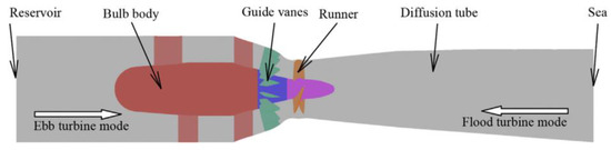
Figure 3.
The flow path of a bidirectional bulb tubular turbine [32].
The initial research on tidal power generation commenced in Germany and France in the early 20th century. The Busum tidal power station in Germany, established in 1912, was the inaugural facility to harness tidal energy globally, and the Longs tidal power station in France, with an installed capacity of 240 MW, signified the transition of tidal energy into practical use. China possesses abundant tidal energy resources, with exploitable tidal energy constituting 37% to 44% of the global total [33]. The largest in Asia, Jiangxia tidal power station, was built in the 1980s, and there are numerous reservoirs fit for the growth of tidal power plants in China’s coastal regions [34]. With a capacity of 2.54 × 10⁵ kW, the large-scale tidal power station at Sihwa Lake, South Korea, is now the biggest one in the world. Table 2 shows the most prominent tidal power plants worldwide.
Table 2.
Details of the leading tidal power stations in the world.
2.3. Wave Energy
Three-level energy conversion systems make up the majority of wave energy converters (WECs): Wave energy is firstly transformed into kinetic energy of air by specific devices at the primary level, then into mechanical energy by rotating machinery (such as a gear speed increasing mechanism, hydraulic turbine, air turbine, etc.) at the secondary level. Finally, the mechanical energy of rotating machinery is transformed into electrical energy by a generator at the third level.
Oscillating water column (OWC), oscillating body (OB), and overtopping WECs are the three categories into which the world’s current wave energy consumption technologies can be categorized based on the primary level conversion principles.
2.3.1. Oscillating Water Column (OWC) WECs
OWC utilizes air as the conversion medium, as shown in Figure 4. The primary level is an air chamber with a lower entrance submerged in seawater and an upper orifice connected to the atmosphere. The secondary component is an air turbine, positioned on the top of the air chamber nozzle. The water column oscillates vertically in the air chamber under the wave impacts, causing the air in the compressed air chamber to reciprocate through the nozzle. This process converts wave energy into the pressure and kinetic energy of air, thereby driving the rotation of the air turbine. One of the notable benefits of OWC is that its rotating mechanism is isolated from seawater, resulting in superior anti-corrosion properties, enhanced safety and dependability, and ease of maintenance; the disadvantage is the low efficiency at the secondary level [35].
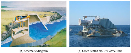
Figure 4.
OWC WECs [35].
Many countries have constructed of OWC power stations, such as the Uisce Beatha 500 kW OWC unit built in Australia, and the 20 kW and 100 kW OWC power stations built by the Guangzhou Institute of Energy Conversion (GIEC) in Zhuhai and Shanwei, respectively. Recently, some new OWC concepts have been proposed in laboratories to improve energy capture performance [36].
2.3.2. Oscillating Body (OB) WECs
Duck WEC
The duck WEC is composed of a main shaft, a duck body, and an underwater support, and it utilizes the energy of the swing of duck body, as shown in Figure 5a. The duck WEC can achieve 90% [37] first-order conversion efficiency; however, the wave resistance of this device still needs to be improved. The duck WEC was first proposed by the British, and the research has mainly been conducted by GIEC. GIEC successively developed the Duck #1~Duck #3 WECs from 2009 to 2013, and Duck #3 is shown in Figure 5b. Duck #3 can adjust its power generation based on wave conditions, achieving a maximum output of 25 kW, which is superior to Duck #1 and Duck #2. But the evolution of duck WEC has been constrained by the excessive mass and moment of inertia.
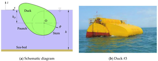
Figure 5.
Duck WECs [37].
Eagle WEC
GIEC created the eagle WEC by combining the duck WEC with the semi-submersible ship in order to solve the flaws in the former. Mostly, the device consists of the semi-submersible ship, the energy conversion system, and the eagle type floating body. “Eagle #1” uses a 10 kW installed capacity combining hydraulic and direct drive power generating systems [38]. “Wanshan” can produce power in any wave conditions by converting wave energy using two sets of independent and parallel hydraulic systems [39]. In addition, more WECs, such as “Leader #1,” “Penghu” [15], “Zhoushan,” and “Mintou #1” [16], have been built in recent years, as shown in Figure 6.
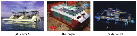
Figure 6.
Eagle WECs [40].
Oscillating Float Type WEC
The oscillating float type WEC [41] generally consists of a moving floating body, anchor chain, and power generating equipment, and the wave energy is absorbed through the relative motion between dynamic floating bodies and relatively stable floating bodies, as shown in Figure 7a, and a typical engineering practice is shown in Figure 7b. Some new concepts, for example, combining Piezoelectric Energy Harvesting with oscillating float [42] to capture the energy from wave motion, have been proposed in recent years. In China, the 1 kW and 120 kW oscillating float type WECs developed by Southeast University and Shandong University, respectively, represent early-stage engineering demonstrations. Recently, researchers proposed a concept to install multiple floating-point absorbers on a large frame to share a power take-off system for realizing small volume and high installed capacity, which is called a multi-body composite system [43,44]. Some examples include “Haiyuan #1” (China) [45], “Hailing” (China) [46], Wave Star (Denmark) [47], Powerbuoy (USA) [48], AquaBUOY (USA) [49], F03 device (Norway) [50], etc.
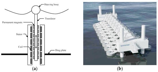
Figure 7.
Oscillating float type wave energy generators: (a) a schematic diagram and (b) the Wave Star device in Denmark [51].
Pendulum and Raft Type WECs
The pendulum type WEC [52] features a pendulum flap that oscillates to capture wave energy in near-shore and seabed locations, meeting the performance criteria of effectiveness, efficiency, environmental sustainability, and cost-effectiveness, as illustrated in Figure 8a. The raft type WEC consists of a hinged raft and a hydraulic system, as illustrated in Figure 8b. The raft oscillates with the waves, activating the engine to produce electricity by the hydraulic system. The main advantages of the raft type WEC are the suitable displacement and good wave resistance performance, and its efficiency can be enhanced by increasing degrees of freedom [53]. However, the material usage per unit of power will be increased if the converter is arranged in the wave direction [46].
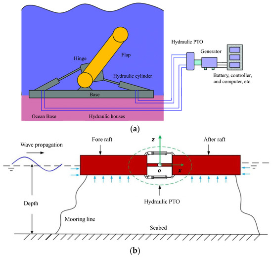
Figure 8.
Pendulum type and raft type WECs: (a) pendulum type [54] and (b) raft type [55].
Based on the pendulum and raft technology, some attempts have been made, such as the “Hailong 1” raft Hydraulic WEC, the British raft device “Pelamis,” the Scottish pendulum device “Oyster,” and the 100 kW bottom hinged pendulum WEC developed by the national marine technology center, as shown in Figure 9.
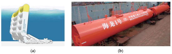
Figure 9.
Applications of pendulum type and raft type WECs: the (a) Scottish pendulum “Oyster” [5] and (b) “Hailong #1” raft type WEC.
2.3.3. Overtopping WEC
Contraction Channel
The contraction channel device [56] consists of a contraction channel, a high-level reservoir, a turbine, and a generator, as seen in Figure 10. The channel’s seaward side features a broad opening that progressively narrows towards the elevated reservoir, and the wave height is incessantly augmented. The wave crest surpasses the lateral boundary of the contraction channel and enters the elevated reservoir, therefore converting wave energy into potential energy to generate electricity through the hydro-turbine. Because the horn-shaped contraction channel is used at the primary level, the energy loss is reduced, and the reliability is improved. However, this method imposes stringent constraints on construction sites, constrained by the contraction ramp or sloped terrain.
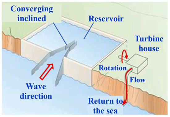
Figure 10.
Schematic diagram of the contraction channel.
Table 3 shows a technological comparison of WECs. The oscillating float type wave energy generator displays higher performance in actual application with reduced construction cost and difficulty based on the analysis of WECs and their corresponding relevant scenarios. This generator is widely studied in Asia, Europe, and the United States, so it is also known as the “Third generation WEC” [57].
Table 3.
Comparison of WECs.
Overtopping WEC (OWEC)
The contraction channel technology is applicable in coastal regions with deep water close to a rocky coastline, but not suitable for countries where the coast generally consists of gentle sloped beaches, because the waves lose the majority of their energy content through bottom friction and wave breaking before they reach the shore. Thus, the overtopping device, which is similar to the traditional hydroelectric power station and uses an axial flow turbine [56], has been proposed, as shown in Figure 11. The OWEC adapts turbines, which have been widely used in hydroelectric power generation systems for many years, and the floating design makes it possible to move them to regions with larger wave energy density. Two typical engineering practices of overtopping devices are Sea Power from Sweden and Wave Dragon (WD) from Denmark: Sea Power has been tested in the prototype scale, and WD is equipped with wave reflectors that focus the waves on the slope.
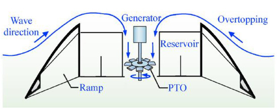
Figure 11.
Schematic diagram of the overtopping device [56].
2.4. Tidal Current Energy
2.4.1. Horizontal Axis Type
The flow direction of a horizontal axis tidal current turbine is parallel to the rotating axis of the runner, and the blades are evenly spaced on the hub. The lift and torque under the action of flow drive the runner to rotate and then convert the kinetic energy into rotating mechanical energy [58]. In contrast to the vertical axis type, the horizontal axis type tidal current turbine has great efficiency, excellent self-starting capability, and stability, which is more appropriate for large tidal current turbines above 500 kW, as shown in Table 4. However, the complex structure of turbines can cause cavitation more easily, and the reversing or pitch mechanism is required to adapt to the bidirectional characteristics of the tide [59].
Table 4.
Main parameters of large tidal current turbines.
According to the survey by Corsatea et al. [60], the research and development of horizontal axis tidal current turbine consumes 76% of the total investment in tidal current energy. The SeaGen S turbine [61], developed by MCT (Marine Current Turbine) in the UK, uses two counter-rotating horizontal axis tidal current turbines, and is the world’s first MW level tidal current turbine, as shown in Figure 12a. In China, Zhejiang University developed 5 kW and 25 kW underwater turbines successively [62]. The Irish OpenHydro company designed the OpenHydro turbine with nose cone [63], where the runner adopts the multi-blade grid design with no rotating shaft in the center. The generator is integrated and installed in the shell to simplify the transmission and regulating mechanism, as shown in Figure 12b. Scotrenewables Tidal Power has developed the floating tidal current turbine from SR250 (250 kW) to SR2000, and the passive steering alignment device and non-adjustable pitch blades are simplified to reduce the manufacturing difficulty and cost. In addition, Altantis Resources designed “AR-1000” with a 1 MW single rotor and “AK-1000” with 1 MW double rotors [64], which is suitable for bidirectional flow. To guarantee the turbine is constantly facing the arriving flow, GE-Alstom designed the 1 MW horizontal axis tidal current turbine with a yaw control system [59], Northeast Normal University designed the 2 kW direct-drive horizontal axis tidal current turbine [65], and Harbin Engineering University developed the 200 kW floating “Haineng II” device [64]. Most of these turbines are still in the demonstration phase and are still far from business applications [64].
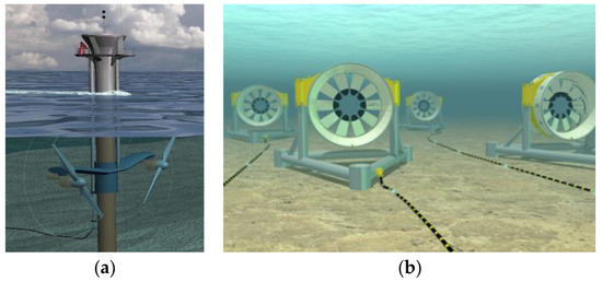
Figure 12.
Applications of horizontal axis tidal current turbines: the (a) SeaGen S Turbine [61] and (b) OpenHydro turbine [66].
2.4.2. Vertical Axis Type
The vertical axis tidal current turbine’s flow direction is perpendicular to the runner’s rotating axis, and the blades span the shroud evenly. The lift, resistance, and torque under the action of flow drive the runner to rotate [58]. The vertical axis tidal current turbine has the following advantages [67].
(a) The blade adopts a symmetrical airfoil structure, which is simple and easy to manufacture and improves the economic efficiency of the turbine;
(b) The generator can be placed above the runner to reduce the difficulty of underwater sealing;
(c) It can better adapt to the turbulent environment [68], so the flow from any direction can be used, and there is no need for any yaw equipment;
(d) The low operating speed reduces the cavitation risk and blade tip loss, which is conducive to reducing noise and protecting the habitat of marine organisms [69].
However, the vertical axis tidal current turbine exhibits low self-starting capability, significant torque fluctuations, and typically worse efficiency compared to the horizontal turbine, hence constraining its advancement.
Mostly composed of Encurrent tidal current turbines developed by NE business in Canada, vertical axis tidal current turbines include the CGen tidal current turbine designed by ORP company in the United States and the Davis four blade tidal current turbine designed by Blue Energy of Canada [70]. In China, Harbin Engineering University has conducted tests of small power model prototypes in laboratories and tested a 40 kW prototype at sea [71]. In 2008, Ocean University of China performed 5 kW prototype offshore testing and refined the vertical axis flexible blade and turbine rotor [72]. Currently, the capacity of vertical axis tidal current turbines can attain megawatt levels, with a representative example illustrated in Figure 13.
Figure 13.
Vertical axis tidal current turbine [73].
2.5. Temperature-Difference Energy
The medium and process allow one to separate the usage technique of the temperature-difference energy into open cycle, closed cycle, and hybrid cycle, as shown in Figure 14. Ocean temperature-difference energy is used to heat and vaporize the medium to drive the steam turbine using the warm seawater on the ocean surface (26 °C~28 °C). Concurrently, the exhaust steam is condensed from the bottom (4 °C~6 °C) using cold saltwater, therefore transforming it once more into liquid form.
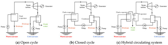
Figure 14.
Schematic diagram of the open cycle, closed cycle, and hybrid cycle.
Although the thermal cycle of temperature-difference energy consumption is based on the Rankine cycle, the limited temperature difference available results in only roughly 3% thermal efficiency of the Rankine cycle [74]. The Kalina Cycle suggested in 1981, which employs an ammonia water combination as the working medium [75], can reach 4.5% thermal efficiency and match the heat and cold sources to satisfactory degrees. When entering the evaporator, the Uehara cycle suggested in 1994 uses an ammonia water mixture as the working medium [76] to further raise the temperature of the working medium and lower the heat absorption, thereby optimizing the efficiency at 4.97%. Using an ammonia water mixture as the working medium, the first National Oceanic Administration of China suggested the National Marine cycle in 2012 [77,78]. Based on secondary regeneration, it cleverly positioned the extraction regeneration following the regeneration of a lean ammonia solution so that more working medium could enter the turbine for operation. The cycle with the highest thermal efficiency thus far reaches 5.1%.
2.5.1. Open Cycle
The open cycle is also called the flash method or Claude cycle, as shown in Figure 14a. The open cycle uses the warm seawater on the ocean surface as the working medium, and it can generate freshwater while generating electricity. A large amount of energy is consumed in the process of open cycle. When the system has problems such as low efficiency, excessive loss, and poor sealing, it will lead to a decline in production capacity or an increase in energy consumption, and the net energy of the system will decline or even be negative [9].
2.5.2. Closed Cycle
The working principle of the closed circulation system [79] is shown in Figure 14b. Warm seawater heats ammonia and another low boiling working medium through a heat exchanger (evaporator) to evaporate. The advantages of the closed cycle are that the working medium with low boiling point can evaporate at a higher pressure or condense at a lower pressure, which improves the pressure differential of the turbine. Consequently, the dimensions and mechanical energy expenditure of the turbine, along with the energy consumption of the working medium, can be minimized, hence enhancing the system’s conversion efficiency. Nevertheless, freshwater cannot be procured during energy generation. Recently, research conducted by Lu et al. [80] found that the performance of a closed Rankine cycle can reach output power of 48 kW, isentropic efficiency of 80%, and maximum system efficiency of 2%.
2.5.3. Hybrid Cycle
The hybrid cycle mixes the benefits of the closed and open cycles. It can generate both electricity and freshwater to realize the comprehensive utilization of seawater, as shown in Figure 14c. The primary level is the open cycle, which is mainly used for seawater desalination, and the secondary level is the closed cycle, which is mainly used to generate electricity. Due to the complex structure, the engineering cost is high and the economy is low in practical engineering applications.
2.6. Salinity-Gradient Energy
The utilization of salinity-gradient energy mainly includes pressure delayed osmosis (PRO) and reverse electroosmosis (RED) [81], as shown in Figure 15. The positive combination of the pressure gradient and salinity gradient shows great potential in power enhancement and is a new trend in research [82].
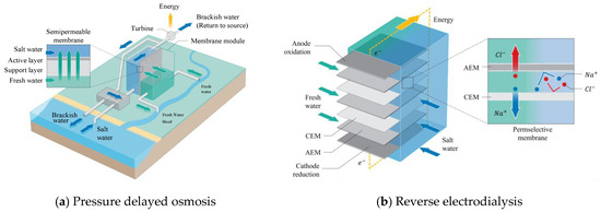
Figure 15.
Schematic diagram of RED and PRO [83].
2.6.1. Pressure Delayed Osmosis (PRO)
PRO adopts permeable membrane to separate seawater and freshwater, which allows freshwater to permeate into the seawater side and drive the connected turbine to rotate, therefore enabling the realization of the goal of transforming salinity-gradient energy into electric power [84], as shown in Figure 15a. In PRO, the salinity gradient across the membrane generates significant osmotic pressure, resulting in a seepage pressure reduction exceeding 30 bar. The disadvantages of PRO are high power generation cost, large equipment investment, low energy conversion efficiency, and low energy density. In addition, in order to prolong the service life of the osmotic membrane, the positions of the anode and cathode in the osmotic membrane must be frequently switched.
Since PRO is a permeation process based on a semi-permeable membrane, the performance of the semi-permeable membrane is directly related to the performance of the PRO process. Nano-porous membranes have good water and salt resistance, which is widely used in reverse osmosis (RO) processes, such as seawater desalination and water purification [85,86,87]. Nano-porous graphene is a kind of typical two-dimensional RO membrane material [88,89,90,91,92] that shows good performance in water flux [93], water and salt blocking [94,95], ion rejection rate [96], and ion selectivity [97].
2.6.2. Reverse Electrodialysis (RED)
As shown in Figure 15b, the RED brings freshwater and saltwater into the membrane array made of alternating cation and anion exchange membranes to directly produce ion flux and electrochemical potential for power generation. This power generating technique is expensive, but it has zero emission, no environmental contamination, great storage range, high energy density, and long operating time. RED has better power generating efficiency than PRO and requires less supporting equipment, which is more appropriate for the present micro system trend of development [98]. With the development of nano processing technology, the pore size of the ion exchange membrane is also developing towards the nanometer level [99].
In 1954, Pattle et al. [100] first demonstrated the feasibility of applying RED to power generation [101,102,103,104] and found that reduced membrane spacing [103] and flow resistance between layers shorten the length of the flow channel and can improve the performance of RED device [105]. Veerman et al. [106] developed a RED device with 50 layers of ion exchange membrane and a power density of 0.93 W/m2. Dlugolecki et al. [107] found that the concentration polarization effect in the interlayer will have a negative impact on the RED process, and the measured output power and energy conversion efficiency are far lower than the theoretical prediction. Kang et al. [108] used the by-product (high-concentration seawater) of RO as the high-concentration solution in the RED process and seawater as the low-concentration solution to recover the unused salinity-gradient energy in the RO process. Deng et al. [109] studied the output power density and corresponding energy efficiency of a multistage RED process.
3. Integration of Marine Renewable Energy System with Aquaculture
Aquaculture, which utilizes the natural marine ecological environment to gather the economic marine organisms released artificially and adopts large-scale fishery facilities and systematic management systems, has developed quickly in recent years. Fish, prawns, shellfish, and algae are among the marine resources planned and purposefully stocked by aquaculture. The construction, operation, and maintenance of aquacultures need energy supply, while the development and utilization of marine renewable energy can achieve this goal more conveniently and quickly. Meanwhile, the integration of marine renewable energy systems and aquaculture can reduce the investment cost and improve the integration level of aquaculture.
3.1. Aquaculture Technology
Offshore aquaculture has seriously polluted and damaged inland bays, mudflats, and other coastal aquaculture waters [110], which can be alleviated through deep offshore aquaculture. With the support of deep-sea aquaculture equipment [111], deep-sea aquaculture can achieve a significant increase or even a doubling in production [112]. At present, gravity type net cages, truss structure net cages, and aquaculture deep-sea ships are the three main types of deep-sea aquaculture facilities and equipment [113,114,115]. Among them, the gravity type net cages have difficulty resisting super typhoon attacks, and the labor cost is high, which is not suitable for deep-sea aquaculture. Therefore, this section mainly summarizes the technical progress of truss structure net cages and deep-sea aquaculture ships.
3.1.1. Truss Structure Net Cage
The earliest form of net cage platform was the transformation of retired oil platforms [116], among which, truss structure net cages mainly include fully submersible, semi-submersible, floating, and bottom-supported types [113]. In recent years, many countries, such as Norway, Denmark, and China, have conducted fruitful research on deep-sea anti-wind and anti-wave net cages [117,118,119,120], and have successively developed dozens of high-performance net cages, as shown in Table 5, which includes the first semi-submersible truss structure net cage in the world, Ocean Farm #1 [120], designed by Norway Global Maritime AS. In China, the semi-submersible platform “Taishan #1” can float the net cage, which facilitates the maintenance of the platform. The semi-submersible platform “Xinhuan #1” has functions for aquaculture and tourism, while the intelligent platform “Zhannong #1” can achieve automatic adjustment of lifting and lowering. Several examples of truss structure net cages are shown in Figure 16.
Table 5.
Examples of truss structure net cages in the world.
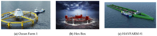
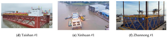
Figure 16.
Several examples of truss structure net cages [121].
3.1.2. Deep-Sea Aquaculture Ship
Deep-sea aquaculture ships have the characteristics of safety, efficiency, and environmental protection, and are an important direction for the development of deep-sea aquaculture. Developed fishing countries in Europe and America proposed the concept of the deep-sea aquaculture ship in the 1980s and created corresponding scheme designs. However, due to the abundant offshore fishing resources and large development space for offshore aquaculture, the motivation to develop deep-sea aquaculture is insufficient and most deep-sea aquaculture ships are still in the conceptual design, feasibility study, and experimental phases. At present, many countries [122,123] have become involved in the deep-sea aquaculture ship. A typical case is the “Eidsfjord Giant” [124], developed in Norway in 2021, with a size of 270 m × 41 m and a total water body of 69,000 m3, as shown in Figure 17a. In China, deep-sea aquaculture ships can effectively cope with the frequent occurrence of typhoons in Chinese waters, while also achieving the production of fish from the south to the north and fish from the north to the south, as well as meeting the industrial demand for high-quality aquaculture throughout the season. The 3000 t “Lulanyu 61699” deep-sea aquaculture ship created in 2017 has functions such as aquaculture, processing, and comprehensive services. The 8000 t “Mingde” deep-sea aquaculture ship proves the feasibility of converting an old ship into a deep-sea aquaculture ship. However, the ship was not equipped with aquaculture equipment, which affected production efficiency. In 2022, the first 100,000 t intelligent fishery large-scale deep-sea aquaculture ship in the world, “Guoxin #1,” was developed for operation [125], as shown in Figure 17b.
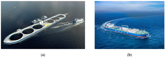
Figure 17.
Typical deep-sea aquaculture ships: (a) Eidsfjord Giant [124] and (b) Guoxin #1.
3.2. Multi-Energy Complementarity
By integrating the capture, conversion, power generation, and supply of wind, solar, wave, tidal current, and other energies into one system, the integrated platform for marine multi-energy integrated power generation can be established [126]. In addition, the system analysis and design, power processing, and information communication of multi-energy integration should be integrated and constructed, so that multi-level and efficient utilization of multi-energy can be realized [127].
3.2.1. Wind–Wave Energy Complementary Technology
The utilization of offshore wind and wave energy is one of the hot topics in marine renewable energy technology. Many researchers improved the wind–wave energy complementary efficiency and the marine space utilization rate, optimizing the construction and operation costs. The current offshore wind–wave energy complementary platform can be classified into three types: the independent complementary type, hydraulic energy storage type, and mechanical coupling type.
Independent Complementary Type
The independent complementary type is the most widely used and the most mature technology at present. The wind turbine and the WEC operate independently, but share one platform, and the generated electricity is connected to the grid centrally, i.e., the energy coupling mode is generally the power grid coupling.
The wind–wave complementary platform, Poseidon 37 [128], which adopts the horizontal axis wind turbine and oscillating float type WEC, has been built by a floating power plant company in Denmark, as shown in Figure 18a. The Shandong Daguan island wind–solar–wave complementary system realized complementary power generation and continuous power supply and solved the problem of power consumption difficulties for residents on the island [129]. The independent complementary system is essentially only a complementary form of the unified allocation of standalone energy generation, which increases the complexity of the system and the difficulty of maintenance.
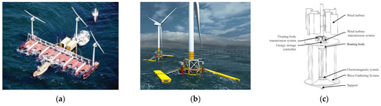
Figure 18.
Wind–wave energy complementary platforms: (a) independent complementary [128], (b) hydraulic energy storage [130], and (c) mechanical coupling.
Hydraulic Energy Storage Type
The development of the hydraulic energy storage type involves energy storage technology. It converts unstable wave energy and wind energy into hydraulic energy with strong stability and good sustainability using energy collection devices.
The use of oscillating float type WECs and wind turbines is the main form of the hydraulic energy storage type. The study by Gu et al. [131] shows that the combination of a 15 MW offshore floating wind turbine and a WEC provides about an 11.4% additional contribution of wave energy, and the WEC array improves the stability and power production of the combined system [132]. The Green Marine energy Company of Scotland developed the wave Treader wind wave complementary power generation device [129] in 2011, as shown in Figure 18b. North China Electric Power University successfully developed the wind–wave energy complementary platform [133] in 2013, which converted the power into hydraulic energy for power generation. In addition, the integration of an offshore floating wind turbine and a duck WEC has proven that the WEC array improves the stability of wind power output and can be used as an effective supplement to power generation [134].
Mechanical Coupling Type
The mechanical coupling type systems [135] convert the wind and wave energy into mechanical energy, and finally drive the generator to generate electricity. Zhonghuiming (Xiamen) Offshore Power Research Institute developed a mechanical coupling platform based on vertical axis wind turbines in 2012, as shown in Figure 18c.
3.2.2. Wind–Tidal Current Energy Complementary Technology
The complementary power generation of wind energy and tidal current energy can be realized by coupling wind turbine and tidal current turbines, as shown in Figure 19. In 2012, Minesto of Sweden combined an “Underwater kite” tidal energy convertor [136] with a wind turbine to form a platform [137] for the marine microgrid system, and provided power for the operation and communication of the buoy. Using a hybrid power generating system with a horizontal axis wind turbine and tidal current turbine, Xi’an University of Technology developed mechanical energy from wind and tidal current energy in 2018 [138]. Using horizontal axis wind turbines and tidal current turbines in 2013, Shanghai Ocean University transformed wind and tidal current energy into mechanical energy and sent it to the mechanical coupling mechanism of a differential gear train [139].
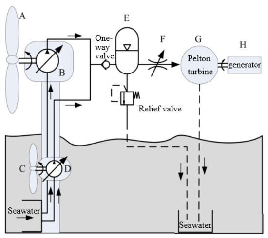
Figure 19.
Schematic diagram of a wind–tidal current energy complementary platform [138].
3.2.3. Subsubsection
Usually fastened by pile foundation, offshore wind turbine operation can be attained with the single-pile design of a wave energy–tidal current energy complementary generation system, as shown in Figure 20. A typical case is a wind–wave–tidal current complementary power generation system designed by Dalian University of Technology. The upper part is a wind turbine, the middle part is a WEC, and the lower part submerged in water is a tidal current turbine. The system lowers the structural complexity and increases the compactness of the wind turbine by using the WEC and tidal current turbine as its piling base and increases the diversity of energy acquisition and the power output.
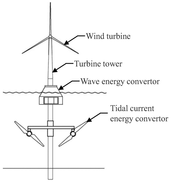
Figure 20.
Wind–wave–tidal current energy complementary system [137].
3.3. Integration of Aquaculture with Standalone Energy
3.3.1. Aquaculture–Offshore Wind Energy
Structural integration and geographical integration mostly define the integration of offshore wind energy with aquaculture, as shown in Figure 21. Whereas spatial integration sets breeding facilities in the areas of offshore wind farms, structural integration uses the wind turbine infrastructure as the aquaculture cage frame. The technical risk of structural integration is higher than the spatial integration, and the spatial integration is relatively easy to achieve [140].
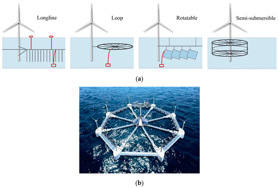
Figure 21.
Aquaculture–offshore wind energy integration technology: (a) conceptual scheme proposed by the German Feasibility Project [13] and (b) platform integrating aquaculture and offshore wind energy.
Since 2000, nations including Germany, the Netherlands, Belgium, and South Korea have conducted research projects on the integration of offshore wind energy with aquaculture. The Netherlands’ “Open Ocean Multi-Use” project, started in 2012, has shown the viability of combining a seaweed aquaculture system with a wind farm; similarly, the “Edulis” project, started in Belgium, and the “Hex Box” project [141], designed by Norway Ocean Aquafarms Co., Ltd., in 2017 also demonstrated both technical and financial viability of aquaculture and wind energy. Furthermore, the first national project is the integrated development of offshore wind energy and aquaculture in the national aquaculture demonstration area in Yantai City, Shandong Province; China Guangdong Nuclear Power Group and Fujian Fisheries Research Institute also established metal aquaculture cages in the wind farm.
3.3.2. Aquaculture–Solar Energy
The integration of aquaculture and solar energy is also named fishery–solar complementation, which saves energy and improves aquaculture efficiency. The solar panels erected on the water surface can effectively block the absorption of solar radiation and reduce the water temperature, which not only is conducive to aquaculture, but also can improve the power generation efficiency of solar panels.
The large intelligent aquaculture complex platform “Genghai #1” [142] arranges the offshore photovoltaic panels on the complex platform to meet the production and lighting requirements, and the artificial reefs placed under the sea helps improve the marine ecological environment and provides attachment growth points for a large number of algae and shellfish, thus achieving the purpose of marine carbon sequestration, as shown in Figure 22a. In 2023, the semi-submersible deep-sea intelligent aquaculture tourism platform “Pusheng aquaculture #3” (Figure 22b), developed and designed by GIEC, was created [142]. The platform is powered by photovoltaic exclusively to achieve energy self-sufficiency, and living facilities such as seawater desalination, sewage treatment, storage space, leisure restaurant, etc., are equipped.
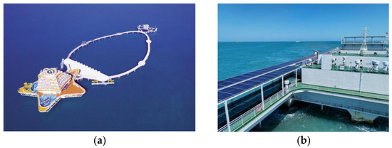
Figure 22.
The integration of aquaculture and solar energy: (a) Genghai #1 [142] and (b) Pusheng aquaculture #3 [142].
3.4. Integration of Aquaculture with Multi-Energy
The integration of aquaculture with multi-energy improves space utilization and reduces overall platform costs, as shown in Figure 23.
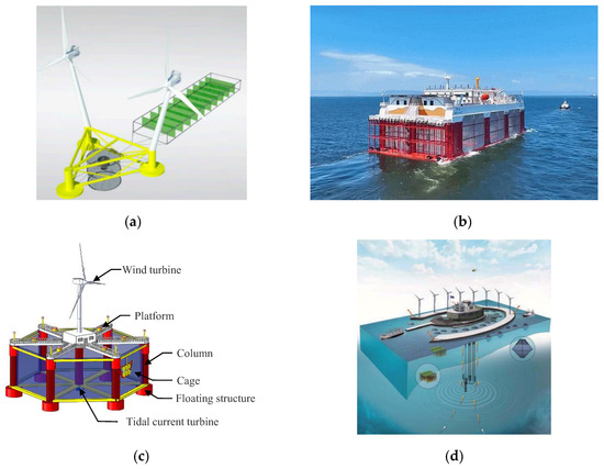
Figure 23.
The integration of aquaculture with multi-energy: (a) aquaculture–offshore wind–solar energy [143], (b) aquaculture–wave–solar energy, (c) aquaculture–offshore wind–tidal current energy [144], and (d) aquaculture–offshore wind–temperature-difference energy [145].
3.4.1. Offshore Wind–Solar–Aquaculture
The EU TROPOS project proposes a Satellite Unit (see Figure 23a) [143], which combines wind turbines, photovoltaic solar panels, aquaculture fish facilities, and an algae farm. Whether floating, submerged, or drifting, the fish culture module will make use of the platform’s facilities, i.e., energy, protection, anchoring, and logistics connected with installation, maintenance, and operation. Appropriate technical components (like cages) should be included in the aquaculture module, and the medium-sized system additionally includes hatcheries for on-site production of young fish and processing facilities for commercial fish. Processing units integrate fishery activities, including industrial processing facilities for fishery products (such as freezing, canning, fumigation, refrigeration, packaging, etc.), which has significant economic benefits for fishing fleets [145]. The particular position will shape the development of the secondary culture around the cage into bivalves or macroalgae. Furthermore, bottom culture can develop if the depth permits it.
3.4.2. Wave–Solar–Aquaculture
In order to overcome the instability and intermittence of solar energy, the complementation of wave energy and solar energy guarantees the safe and stable use of electricity in aquacultures.
In June 2019, China established its first semi-submersible wave energy aquaculture cage, “Penghu,” developed by GIEC [15], which is equipped with a 60 kW wave energy absorbing floating body to absorb wave energy and 60 kW solar panels to make full use of the abundant solar energy. Offshore wind turbines can also be installed around the platform in the sea area with abundant and stable wind energy resources. In 2022, the mobile semi-submersible wave energy–aquaculture tourism platform, “Mintou #1,” was successfully launched, equipped with a 100 kW wave turbine, a 240 kW photovoltaic power generation system, and a 1204 kWh marine high-safety battery pack [142], which realizes the green power supply of multi-energy complementation, as shown in Figure 23b. In addition, Norway’s Havkraft n-class wave power station has experimented with the integrated development mode of wave power generation and aquaculture.
3.4.3. Offshore Wind –Tidal Current–Aquaculture
Wind turbine is greatly affected by the environment and needs to shut down under rough sea conditions; normal control system operations should be ensured to ensure that the onshore control center obtains the relevant status of the aquaculture equipment in time.
However, the flow velocity of tidal current is less affected by wind, and tidal current turbines can operate normally under extreme conditions to provide stable power, ensuring the energy stability of the overall platform. For example, Ma et al. [144,146] designed the semi-submersible aquaculture device (Figure 23c), “Haiyang fishing ground #1,” which combined the fishery aquaculture with wind turbines and tidal current turbines.
3.4.4. Offshore Wind Energy–Temperature-Difference–Aquaculture
The possibility of bringing deep-sea water to the surface, thereby generating an artificial upwelling associated with thermoelectric power generation, is related to the integration of aquaculture with offshore wind energy and temperature-difference energy (Figure 23d). Integrating the structure with large-scale wind turbines or WECs is beneficial to the ecosystem and improves the productivity of aquaculture facilities [145].
More advanced ideas incorporate artificial coral reefs to boost fish numbers and build devices to guard and aggregate plankton, as well as fish in larval stages. A specific example is the combination of algae cultivation with green energy components.
3.5. Discussion
3.5.1. Main Research and Application Progress
The main research and application processes of marine renewables and their integration with aquaculture can be described as follows.
(a) The development of standalone marine renewable energy shows significant differences in progress. Tidal energy and offshore wind energy technologies have achieved mature commercial operation, while tidal current energy and wave energy technologies are undergoing full-scale prototype testing. Temperature-difference energy technology has reached the full-scale prototype testing phase, whereas salinity-gradient energy technology remains in the laboratory verification stage.
(b) Integrating the capture, conversion, power generation, and supply of marine renewables into one system is a complex issue, which involves not only structural coupling, but also the integration of system analysis and design, power processing, and information communication of multi-energy to achieve multi-level efficient utilization of multi-energy.
(c) The development of aquaculture relies on the development of gravity type net cages, truss structure net cages, and deep-sea aquaculture ships. The gravity type net cages are not suitable for deep-sea aquaculture due to their shortcomings of low typhoon resistance capability and high labor cost. Truss structure net cages and deep-sea aquaculture ships show great potential in deep-sea aquaculture.
(d) The early attempts to integrate marine renewable energy with aquaculture mainly focus on standalone marine renewable energy, wherein the utilization of solar energy on the platform is the simplest method. Integration of marine renewable energy with aquaculture has structural and geographical integration forms; spatial integration is relatively easy to achieve and has been widely adopted in engineering.
3.5.2. Future Prospection
Some insights and recommendations for future research on the integration of marine renewable energy and aquaculture are as follows.
(a) There are still many problems that need to be overcome for the development of standalone marine renewable energy: for example, the design of floating wind turbines, the improvement of tidal energy economy, and the development of temperature-difference and salinity-gradient energy utilization technologies.
(b) Integration of marine renewables is not yet mature, and the current integration technology essentially integrates different forms of energy converters on one platform. More studies are needed to realize the deep integration of multi-energy systems.
(c) Most of the current aquaculture–marine renewable energy integration technologies are in the conceptual design stage, and the integration form is relatively simple. The feasibility of integration technologies, such as offshore wind–solar, wave–solar–aquaculture, offshore wind–tidal current–aquaculture, offshore wind energy–temperature-difference–aquaculture, wind–wave–aquaculture systems [17], etc., needs more in-depth study and analysis.
(d) The current goal of integration technology is mainly to supply power to aquaculture platforms. How to integrate high-capacity power generation units with aquaculture needs more research.
(e) Obviously, the fewer forms of energy converter, the simpler the aquaculture–marine renewable energy platform. Thus, the necessity of integrating aquaculture with multi-energy should be demonstrated, and an appropriate scheme should be selected.
4. Conclusions
This paper delineates the advancements in marine renewable energy utilization technologies globally, encompassing offshore wind energy, tidal energy, wave energy, tidal current energy, temperature-difference energy, and salinity-gradient energy, with an emphasis on research focal points and variations in device mechanisms. The primary conclusions are as follows.
(a) Globally, tidal energy and offshore wind energy technologies have achieved mature commercial operation, while tidal current energy and wave energy technologies have progressed to full-scale prototype state testing. Temperature-difference energy technology has also reached the full-scale prototype sea state testing phase, whereas salinity-gradient energy technology remains in the laboratory verification stage.
(b) There are significant differences in marine renewable energy utilization technologies among countries. In recent years, universities and research institutions in multiple countries have conducted many engineering tests, but further breakthroughs are needed in key energy harvesting technologies and safety.
(c) One can regard the development and construction scheme of aquaculture integrated energy platforms as the integration of aquaculture with offshore wind energy and wave energy/tidal current energy. Compared with the structural integration of offshore wind energy and aquaculture, which is considered deep integration, spatial integration is relatively easy to achieve due to its low technical risk.
Overall, this paper analyzes the research and applications of marine renewable energy utilization technologies and possible integration roadmaps with aquaculture, and discusses the development stages, opportunities, and difficulties of the marine renewable energy use technologies engaged in this emergence, providing a reference for integrating marine renewables with aquaculture.
Author Contributions
Conceptualization, Y.L.; investigation, H.H.; writing—original draft preparation, J.C. and J.L.; writing—review and editing, C.Z.; supervision and project administration, X.L. All authors have read and agreed to the published version of the manuscript.
Funding
This research was funded by the science and technology project of China Huaneng Group Co., Ltd., grant number HNKJ25-H29.
Institutional Review Board Statement
Not applicable.
Informed Consent Statement
Not applicable.
Data Availability Statement
Not applicable.
Conflicts of Interest
The authors declare no conflicts of interest.
References
- McMorland, J.; Collu, M.; McMillan, D.; Carroll, J.; Coraddu, A. Opportunistic maintenance for offshore wind: A review and proposal of future framework. Renew. Sustain. Energy Rev. 2023, 184, 113571. [Google Scholar] [CrossRef]
- Khojasteh, D.; Shamsipour, A.; Huang, L.; Tavakoli, S.; Haghani, M.; Flocard, F.; Farzadkhoo, M.; Iglesias, G.; Hemer, M.; Lewis, M.; et al. A large-scale review of wave and tidal energy research over the last 20 years. Ocean. Eng. 2023, 282, 114995. [Google Scholar] [CrossRef]
- Neill, S.P.; Angeloudis, A.; Robins, P.E.; Walkington, I.; Ward, S.L.; Masters, I.; Lewis, M.J.; Piano, M.; Avdis, A.; Piggott, M.D.; et al. Tidal range energy resource and optimization—Past perspectives and future challenges. Renew. Energy 2018, 127, 763–778. [Google Scholar] [CrossRef]
- Golbaz, D.; Asadi, R.; Amini, E.; Mehdipour, H.; Nasiri, M.; Etaati, B.; Naeeni, S.T.O.; Neshat, M.; Mirjalili, S.; Gandomi, A.H. Layout and design optimization of ocean wave energy converters: A scoping review of state-of-the-art canonical, hybrid, cooperative, and combinatorial optimization methods. Energy Rep. 2022, 8, 15446–15479. [Google Scholar] [CrossRef]
- Li, H.; Shi, X.; Kong, W.; Kong, L.; Hu, Y.; Wu, X.; Pan, H.; Zhang, Z.; Pan, Y.; Yan, J. Advanced wave energy conversion technologies for sustainable and smart sea: A comprehensive review. Renew. Energy 2025, 238, 121980. [Google Scholar] [CrossRef]
- Li, G.; Zhu, W. Tidal current energy harvesting technologies: A review of current status and life cycle assessment. Renew. Sustain. Energy Rev. 2023, 179, 113269. [Google Scholar] [CrossRef]
- Chen, C. Study on Blade Optimization and Hydrodynamic Performance of Horizontal Axis Marine Current Turbine; Ocean University of China: Qingdao, China, 2012. [Google Scholar]
- Jung, H.; Subban, C.V.; McTigue, J.D.; Martinez, J.J.; Copping, A.E.; Osorio, J.; Liu, J.; Deng, Z.D. Extracting energy from ocean thermal and salinity gradients to power unmanned underwater vehicles: State of the art, current limitations, and future outlook. Renew. Sustain. Energy Rev. 2022, 160, 112283. [Google Scholar] [CrossRef]
- Aresti, L.; Christodoulides, P.; Michailides, C.; Onoufriou, T. Reviewing the energy, environment, and economy prospects of Ocean Thermal Energy Conversion (OTEC) systems. Sustain. Energy Technol. Assess. 2023, 60, 103459. [Google Scholar] [CrossRef]
- Cai, Q.; Li, Z.; Hu, J.; Huang, B.; Pan, Y.; Wu, H.; Ren, Z. Fatigue study of unbonded flexible risers for ocean thermal energy conversion based on the joint distribution of wind, wave, and current. Appl. Ocean. Res. 2025, 154, 104306. [Google Scholar] [CrossRef]
- Wang, P.; Liu, Y.; Li, Y.; Tang, X.; Ren, Q. Power prediction for salinity-gradient osmotic energy conversion based on multiscale and multidimensional convolutional neural network. Energy 2024, 313, 133729. [Google Scholar] [CrossRef]
- Griffin, R.; Buck, B.; Krause, G. Private incentives for the emergence of co-production of offshore wind energy and mussel aquaculture. Aquaculture 2015, 436, 80–89. [Google Scholar] [CrossRef]
- Buck, B.H.; Langan, R. The German Case Study: Pioneer Projects of Aquaculture-Wind Farm Multi-Uses; Springer International Publishing: Berlin/Heidelberg, Germany, 2017. [Google Scholar]
- Gharechae, A.; Abazari, A.; Soleimani, K. Performance assessment of a combined circular aquaculture cage floater and point absorber wave energy converters. Ocean. Eng. 2024, 300, 117239. [Google Scholar] [CrossRef]
- Yue, W.; Wang, Z.; Ding, W.; Sheng, S.; Zhang, Y.; Huang, Z.; Wang, W. Feasibility of Co-locating wave energy converters with offshore aquaculture: The Pioneering case study of China’s Penghu platform. Ocean. Eng. 2023, 288, 116039. [Google Scholar] [CrossRef]
- Yue, W.; Wang, W.; Sheng, S.; Ye, Y.; Hong, T. Analysis of the wave load and dynamic response of a new semi-submersible wave-energy-powered aquaculture platform. Ocean. Eng. 2022, 248, 110346. [Google Scholar] [CrossRef]
- Chen, M.; Huang, W.; Liu, H.; Hallak, T.S.; Liu, S.; Yang, Y.; Tao, T.; Jiang, Y. A novel SPM wind-wave-aquaculture system: Concept design and fully coupled dynamic analysis. Ocean. Eng. 2025, 315, 119798. [Google Scholar] [CrossRef]
- Liu, H.; Liu, M.; Liang, Z. Investigation of Three-Dimensional Wake Width for Offshore Wind Turbines Under Complex Environmental Conditions by Large Eddy Simulation. J. Offshore Mech. Arct. Eng. 2024, 147, 22001. [Google Scholar] [CrossRef]
- Jiang, Y.; Cheng, Z.; Chen, P.; Liu, L.; Yang, L.; Xiao, L. Effects of Aerodynamic Damping and Gyroscopic Moments on Dynamic Responses of a Semi-Submersible Floating Vertical Axis Wind Turbine: An Experimental Study. J. Offshore Mech. Arct. Eng. 2024, 147, 1–43. [Google Scholar] [CrossRef]
- McKenna, R.; Ostman, V.D.; Leye, P.; Fichtner, W. Key challenges and prospects for large wind turbines. Renew. Sustain. Energy Rev. 2016, 53, 1212–1221. [Google Scholar] [CrossRef]
- Breton, S.-P.; Moe, G. Status, plans and technologies for offshore wind turbines in Europe and North America. Renew. Energy 2009, 34, 646–654. [Google Scholar] [CrossRef]
- Nizamani, Z.; Muhammad, A.K.; Ali, M.O.A.; Wahab, M.A.; Nakayama, A.; Ahmed, M.M. Renewable wind energy resources in offshore low wind speeds regions near the equator: A review. Ocean. Eng. 2024, 311, 118834. [Google Scholar] [CrossRef]
- Gosselin, R.; Dumas, G.; Boudreau, M. Parametric study of H-Darrieus vertical-axis turbines using CFD simulations. J. Renew. Sustain. Energy 2016, 8, 53301. [Google Scholar] [CrossRef]
- Ashwill, T.D.; Sutherland, H.J.; Berg, D.E. A Retrospective of VAWT Technology; Sandia National Laboratories: Albuquerque, NM, USA, 2012. [Google Scholar]
- Jenkins, N. Engineering wind farms. Power Eng. J. 1993, 7, 53–60. [Google Scholar] [CrossRef]
- Kinzel, M.; Mulligan, Q.; Dabiri, J.O. Energy exchange in an array of vertical-axis wind turbines. J. Turbul. 2013, 14, 38–39. [Google Scholar] [CrossRef]
- Burton, T.; Jenkins, N.; Sharpe, D.; Bossanyi, E. Wind Energy Handbook, 2nd ed.; Wiley: New Delhi, India, 2011. [Google Scholar]
- Jamieson, P. Innovation in Wind Turbine Design, 2nd ed.; Wiley John Sons: Hoboken, NJ, USA, 2018. [Google Scholar]
- Islam, M.R.; Mekhilef, S.; Saidur, R. Progress and recent trends of wind energy technology. Renew. Sustain. Energy Rev. 2013, 21, 456–468. [Google Scholar] [CrossRef]
- Jian, L.; Yuze, S.; Huamei, W.; Xiangnan, W.; Kuan, L.; Hongming, Q. Study on measurement uncertainty of energy conversion efficiency of tidal energy converters. Energy Rep. 2024, 12, 4883–4890. [Google Scholar] [CrossRef]
- Liu, X.; Lu, J.; Ren, T.; Yu, F.; Cen, Y.; Li, C.; Yuan, S. Review of research on wake characteristics in horizontal-axis tidal turbines. Ocean. Eng. 2024, 312, 119159. [Google Scholar] [CrossRef]
- Luo, Y.; Wang, Z.; Liu, X.; Xiao, Y.; Chen, C.; Wang, H.; Yan, J. Numerical prediction of pressure pulsation for a low head bidirectional tidal bulb turbine. Energy 2015, 89, 730–738. [Google Scholar] [CrossRef]
- Liu, L.-Q.; Liu, C.-X.; Sun, Z.-Y.; Han, R.-C. The development and application practice of neglected tidal energy in China. Renew. Sustain. Energy Rev. 2011, 15, 1089–1097. [Google Scholar] [CrossRef]
- Mazumder, R.; Arima, M. Tidal rhythmites and their implications. Earth Sci. Rev. 2005, 69, 79–95. [Google Scholar] [CrossRef]
- You, Y.; Li, W.; Liu, W.; Li, X. Development status and perspective of marine energy conversion systems. Autom. Electr. Power Syst. 2010, 34, 1–12. [Google Scholar]
- Yang, S.; Zhu, W.; Tu, Y.; Cao, G.; Chen, X.; Du, Z.; Fan, J.; Huang, Y. Study on the influence of heave plate on energy capture performance of central pipe oscillating water column wave energy converter. Energy 2024, 312, 133517. [Google Scholar] [CrossRef]
- Wu, J.; Yao, Y.; Zhou, L.; Chen, N.; Yu, H.; Li, W.; Göteman, M. Performance analysis of solo Duck wave energy converter arrays under motion constraints. Energy 2017, 139, 155–169. [Google Scholar] [CrossRef]
- Chen, A.; You, Y.; Sheng, S.; Lin, H.; Ye, Y.; Huang, S. Nonlinear analysis of the crashworthy component of an eagle wave energy converter in rotating-collision. Ocean. Eng. 2016, 125, 285–294. [Google Scholar] [CrossRef]
- Sheng, S.; Wang, K.; Lin, H.; Zhang, Y.; You, Y.; Wang, Z.; Chen, A.; Jiang, J.; Wang, W.; Ye, Y. Model research and open sea tests of 100 kW wave energy convertor Sharp Eagle Wanshan. Renew. Energy 2017, 113, 587–595. [Google Scholar] [CrossRef]
- Lu, Q.; Shi, H. Progress and Future Trend of Wave Energy Technology in China. Costal Eng. 2022, 41, 1–12. [Google Scholar]
- Drew, B.; Plummer, A.R.; Sahinkaya, M.N. A review of wave energy converter technology. Proc. Inst. Mech. Eng. Part A J. Power Energy 2016, 223, 887–902. [Google Scholar] [CrossRef]
- Du, X.; Li, P.; Li, Z.; Liu, X.; Wang, W.; Feng, Q.; Du, L.; Yu, H.; Wang, J.; Xie, X.; et al. Multi-pillar piezoelectric stack harvests ocean wave energy with oscillating float buoy. Energy 2024, 298, 131347. [Google Scholar] [CrossRef]
- Guo, X.; Liu, Y.; Zhang, X. Layout Optimization of Wave Energy Park Based on Multi-Objective Optimization Algorithm. J. Offshore Mech. Arct. Eng. 2024, 147, 42001. [Google Scholar] [CrossRef]
- Sun, P.; He, H.; Chen, H.; Zhang, J.; Li, H. Sensitivity analysis of geometric characteristics on the cavity-buoy for energy capture efficiency enhancement of a semi-submersible floating-array-buoy wave energy converter system. Ocean. Eng. 2024, 294, 116735. [Google Scholar] [CrossRef]
- Li, D.; Li, D.; Li, F.; Shi, J.; Zhang, W. Analysis of Floating Buoy of a Wave Power Generating Jack-Up Platform Haiyuan 1. Adv. Mech. Eng. 2013, 5, 105072. [Google Scholar] [CrossRef]
- Wang, S. Design and Power Calculation Analysis of Oscillating Float-Type Wave Energy Device; Ocean University of China: Qingdao, China, 2013. [Google Scholar]
- Hansen, R.; Kramer, M.; Vidal, E. Discrete Displacement Hydraulic Power Take-Off System for the Wavestar Wave Energy Converter. Energies 2013, 6, 4001–4044. [Google Scholar] [CrossRef]
- Edwards, K.; Mekhiche, M. Ocean Testing of a Wave-Capturing Powerbuoy; Marine Energy Technology Symposium: Washington, DC, USA, 2013. [Google Scholar]
- Wacher, A.; Neilsen, K. Mathematical and numerical modeling of the AquaBuOY wave energy converter. Math. Ind. Case Stud. 2010, 2, 16–33. [Google Scholar]
- Babarit, A. On the park effect in arrays of oscillating wave energy converters. Renew. Energy 2013, 58, 68–78. [Google Scholar] [CrossRef]
- Lai, W. Design and Experimental Study of a Rocker Wave Energy Converter; Zhejiang Ocean University: Zhoushan, China, 2020. [Google Scholar]
- Jiang, X.; Cao, F.; Shi, H.; Zhu, K.; Zhang, C. Optimization of pendulum-based wave energy converter through mathematical approximation. Appl. Energy 2025, 378, 124754. [Google Scholar] [CrossRef]
- Zhao, C.; Han, M.; Johanning, L.; Shi, H. Multi-freedom effects on a raft-type wave energy convertor- hydrodynamic response and energy absorption. Ocean. Eng. 2024, 305, 117964. [Google Scholar] [CrossRef]
- Wan, Z.; Zheng, H.; Sun, K.; Zhou, K. A model and experiment study of an improved pendulor wave energy converter. Energy Procedia 2017, 105, 283–288. [Google Scholar] [CrossRef]
- Liu, C.; Yang, Q.; Bao, G. Performance investigation of a two-raft-type wave energy converter with hydraulic power take-off unit. Appl. Ocean. Res. 2017, 62, 139–155. [Google Scholar] [CrossRef]
- Zhang, Y.; Zhao, Y.; Sun, W.; Li, J. Ocean wave energy converters: Technical principle, device realization, and performance evaluation. Renew. Sustain. Energy Rev. 2021, 141, 110764. [Google Scholar] [CrossRef]
- Falcão, A.F.d.O. Wave energy utilization: A review of the technologies. Renew. Sustain. Energy Rev. 2010, 14, 899–918. [Google Scholar] [CrossRef]
- Khan, M.J.; Bhuyan, G.; Iqbal, M.T.; Quaicoe, J.E. Hydrokinetic energy conversion systems and assessment of horizontal and vertical axis turbines for river and tidal applications: A technology status review. Appl. Energy 2009, 86, 1823–1835. [Google Scholar] [CrossRef]
- Nachtane, M.; Tarfaoui, M.; Goda, I.; Rouway, M. A review on the technologies, design considerations and numerical models of tidal current turbines. Renew. Energy 2020, 157, 1274–1288. [Google Scholar] [CrossRef]
- Corsatea, T.D.; Magagna, D. Overview of European Innovation Activities in Marine Energy Technology; European Commission: Brussels, Belgium, 2013. [Google Scholar]
- Fraenkel, P.L. Development and testing of Marine Current Turbine’s SeaGen 1.2 MW tidal stream turbine. In Proceedings of the 3rd International Conference on Ocean Energy, Bilbao, Spain, 6–8 October 2010. [Google Scholar]
- Liu, H.; Li, W.; Lin, Y.; Ma, S. Model analysis and test research of horizontal-axis marine current turbine. Acta Energiae Solaris Sin. 2009, 30, 633–638. [Google Scholar]
- European Marine Energy Centre (EMEC) Ltd. Available online: http://www.emec.org.uk/about-us/our-tidal-clients/open-hydro/ (accessed on 25 April 2025).
- Ma, Y.; Hu, C.; Li, L. Hydrodynamics and wake flow analysis of a Π-type vertical axis twin-rotor tidal current turbine in surge motion. Ocean. Eng. 2021, 224, 108625. [Google Scholar] [CrossRef]
- Zhang, X. Currents to Power Generation and the Development of Simulator. Master’s Thesis, Northeast Normal University, Changchun, China, 2009. [Google Scholar]
- Borg, M.G.; Xiao, Q.; Allsop, S.; Incecik, A.; Peyrard, C. A Numerical Swallowing-Capacity Analysis of a Vacant, Cylindrical, Bi-Directional Tidal Turbine Duct in Aligned & Yawed Flow Conditions. J. Mar. Sci. Eng. 2021, 9, 182. [Google Scholar] [CrossRef]
- Zeiner-Gundersen, D.H. A novel flexible foil vertical axis turbine for river, ocean, and tidal applications. Appl. Energy 2015, 151, 60–66. [Google Scholar] [CrossRef]
- Satrio, D.; Utama, I.K.A.P.; Mukhtasor, M. Vertical axis tidal current turbine: Advantages and challenges review. Proc. Ocean. Mech. Aerosp. Sci. Eng. 2016, 3, 64–71. [Google Scholar]
- Kirke, B.K.; Lazauskas, L. Limitations of fixed pitch Darrieus hydrokinetic turbines and the challenge of variable pitch. Renew. Energy 2011, 36, 893–897. [Google Scholar] [CrossRef]
- Charlier, R.H. A “sleeper” awakes: Tidal current power. Renew. Sustain. Energy Rev. 2003, 7, 515–529. [Google Scholar] [CrossRef]
- Jing, F.; Sheng, Q.; Zhang, L. Experimental research on tidal current vertical axis turbine with variable-pitch blades. Ocean. Eng. 2014, 88, 228–241. [Google Scholar] [CrossRef]
- Wang, S. Study on Hydrodynamic Performances of a Tidal Current Energy Conversion Device with Flexible Blade Turbine. Ph.D. Thesis, China Ocean University, Qingdao, China, 2009. [Google Scholar]
- Marsh, P.; Ranmuthugala, D.; Penesis, I.; Thomas, G.A. Three-dimensional numerical simulations of straight-bladed vertical axis tidal turbines investigating power output, torque ripple and mounting forces. Renew. Energy 2015, 83, 67–77. [Google Scholar] [CrossRef]
- Zhang, W.; Li, Y.; Wu, X.; Guo, S. Review of the applied mechanical problems in ocean thermal energy conversion. Renew. Sustain. Energy Rev. 2018, 93, 231–244. [Google Scholar] [CrossRef]
- Kalina, A.I. Combined-cycle system with novel bottoming cycle. J. Eng. Gas Turbines Power 1984, 106, 737–742. [Google Scholar] [CrossRef]
- Uehara, H.; IKEGAMI, Y.; NISHIDA, T. Performance analysis of OTEC system using a cycle with absorption and extraction processes. Trans. Jpn. Soc. Mech. Eng. Ser. B 1998, 64, 2750–2755. [Google Scholar] [CrossRef]
- Liu, W.; Chen, F.; Wang, Y.; Jiang, W. Progress of closed-cycle OTEC and study of a new cycle of OTEC. Adv. Mater. Res. 2011, 354–355, 275–278. [Google Scholar] [CrossRef]
- Chen, F. Study on Thermal Performance and Comprehensive Utilization of Ocean Thermal Energy Conversion. Ph.D. Thesis, Harbin Engineering University, Harbin, China, 2016. [Google Scholar]
- Zhang, Y.; Deng, J.; Deng, Z. Thermodynamic and economic analysis of ocean thermal energy conversion system using zeotropic mixtures. Case Stud. Therm. Eng. 2024, 64, 105408. [Google Scholar] [CrossRef]
- Lu, B.; Yu, Y.; Tian, M.; Chen, Y.; Zhang, L.; Liu, Y. Experimental study of a high-power generation platform for ocean thermal energy conversion. Energy 2024, 309, 133115. [Google Scholar] [CrossRef]
- Jiao, Y.; Song, L.; Zhao, C.; An, Y.; Lu, W.; He, B.; Yang, C. Membrane-based indirect power generation technologies for harvesting salinity gradient energy—A review. Desalination 2022, 525, 115485. [Google Scholar] [CrossRef]
- Zhang, Z.; Li, Z.; Shi, Y.; Chen, X.; Qiao, N.; Li, C. The synergistic effects of salinity and pressure gradients on sustainable energy conversion in nanofluidics. Desalination 2024, 586, 117885. [Google Scholar] [CrossRef]
- Siria, A.; Bocquet, M.L.; Bocquet, L. New avenues for the large-scale harvesting of blue energy. Nat. Rev. Chem. 2017, 1, 91. [Google Scholar] [CrossRef]
- Achilli, A.; Cath, T.Y.; Childress, A.E. Power generation with pressure retarded osmosis: An experimental and theoretical investigation. J. Membr. Sci. 2009, 343, 42–52. [Google Scholar] [CrossRef]
- Wang, S.; Liu, H.; Gu, J.; Sun, H.; Zhang, M.; Liu, Y. Technology feasibility and economic viability of an innovative integrated ceramic membrane bioreactor and reverse osmosis process for producing ultrapure water from municipal wastewater. Chem. Eng. J. 2019, 375, 122078. [Google Scholar] [CrossRef]
- Ligaray, M.; Kim, N.; Park, S.; Park, J.-S.; Park, J.; Kim, Y.; Cho, K.H. Energy projection of the seawater battery desalination system using the reverse osmosis system analysis model. Chem. Eng. J. 2020, 395, 125082. [Google Scholar] [CrossRef]
- Wang, P.; Wang, M.; Liu, F.; Ding, S.; Wang, X.; Du, G.; Liu, J.; Apel, P.; Kluth, P.; Trautmann, C.; et al. Ultrafast ion sieving using nanoporous polymeric membranes. Nat. Commun. 2018, 9, 569. [Google Scholar] [CrossRef]
- Suk, M.E.; Aluru, N.R. Water Transport through Ultrathin Graphene. J. Phys. Chem. Lett. 2010, 1, 1590–1594. [Google Scholar] [CrossRef]
- Lohrasebi, A.; Rikhtehgaran, S. Ion separation and water purification by applying external electric field on porous graphene membrane. Nano Res. 2018, 11, 2229–2236. [Google Scholar] [CrossRef]
- Liu, Z.; Wang, W.; Ju, X.; Xie, R.; Chu, L. Graphene-based membranes for molecular and ionic separations in aqueous environments. Chin. J. Chem. Eng. 2017, 25, 1598–1605. [Google Scholar] [CrossRef]
- Gravelle, S.; Yoshida, H.; Joly, L.; Ybert, C.; Bocquet, L. Carbon membranes for efficient water-ethanol separation. J. Chem. Phys. 2016, 145, 124708. [Google Scholar] [CrossRef]
- Song, N.; Gao, X.; Ma, Z.; Wang, X.; Wei, Y.; Gao, C. A review of graphene-based separation membrane: Materials, characteristics, preparation and applications. Desalination 2018, 437, 59–72. [Google Scholar] [CrossRef]
- Xu, J.; Zhu, C.; Wang, Y.; Li, H.; Huang, Y.; Shen, Y.; Francisco, J.S.; Zeng, X.C.; Meng, S. Water transport through subnanopores in the ultimate size limit: Mechanism from molecular dynamics. Nano Res. 2019, 12, 587–592. [Google Scholar] [CrossRef]
- Nguyen, C.T.; Beskok, A. Saltwater transport through pristine and positively charged graphene membranes. J. Chem. Phys. 2018, 149, 24704. [Google Scholar] [CrossRef]
- Li, Z.; Qiu, Y.; Li, K.; Sha, J.; Li, T.; Chen, Y. Optimal design of graphene nanopores for seawater desalination. J. Chem. Phys. 2018, 148, 14703. [Google Scholar] [CrossRef]
- Yu, H.; He, Y.; Xiao, G.; Fan, Y.; Ma, J.; Gao, Y.; Hou, R.; Yin, X.; Wang, Y.; Mei, X. The roles of oxygen-containing functional groups in modulating water purification performance of graphene oxide-based membrane. Chem. Eng. J. 2020, 389, 124375. [Google Scholar] [CrossRef]
- Wang, Y.; He, Z.; Gupta, K.M.; Shi, Q.; Lu, R. Molecular dynamics study on water desalination through functionalized nanoporous graphene. Carbon 2017, 116, 120–127. [Google Scholar] [CrossRef]
- Mejía-Marchena, R.; Maturana-Córdoba, A.; Fernández-Rojano, S. Unveiling the enhancing potential of water pretreatment on energy efficiency in reverse electrodialysis systems—A comprehensive review. J. Water Process Eng. 2023, 56, 104548. [Google Scholar] [CrossRef]
- Jang, J.; Kang, Y.; Han, J.-H.; Jang, K.; Kim, C.-M.; Kim, I.S. Developments and future prospects of reverse electrodialysis for salinity gradient power generation: Influence of ion exchange membranes and electrodes. Desalination 2020, 491, 114540. [Google Scholar] [CrossRef]
- Pattle, R.E. Production of electric power by mixing fresh and salt water in the hydroelectric pile. Nature 1954, 174, 660. [Google Scholar] [CrossRef]
- Suda, F.; Matsuo, T.; Ushioda, D. Transient changes in the power output from the concentration difference cell (dialytic battery) between seawater and river water. Energy 2007, 32, 165–173. [Google Scholar] [CrossRef]
- Turek, M.; Bandura, B. Renewable energy by reverse electrodialysis. Desalination 2007, 205, 67–74. [Google Scholar] [CrossRef]
- Post, J.W.; Hamelers, H.V.M.; Buisman, C.J.N. Energy recovery from controlled mixing salt and fresh water with a reverse electrodialysis system. Environ. Sci. Technol. 2008, 42, 5785–5790. [Google Scholar] [CrossRef]
- Galama, A.H.; Vermaas, D.A.; Veerman, J.; Saakes, M.; Rijnaarts, H.H.M.; Post, J.W.; Nijmeijer, K. Membrane resistance: The effect of salinity gradients over a cation exchange membrane. J. Membr. Sci. 2014, 467, 279–291. [Google Scholar] [CrossRef]
- Veerman, J.; de Jong, R.M.; Saakes, M.; Metz, S.J.; Harmsen, G.J. Reverse electrodialysis: Comparison of six commercial membrane pairs on the thermodynamic efficiency and power density. J. Membr. Sci. 2009, 343, 7–15. [Google Scholar] [CrossRef]
- Veerman, J.; Saakes, M.; Metz, S.J.; Harmsen, G.J. Reverse electrodialysis: Performance of a stack with 50 cells on the mixing of sea and river water. J. Membr. Sci. 2009, 327, 136–144. [Google Scholar] [CrossRef]
- Dlugolecki, P.; Gambier, A.; Nijmeijer, K.; Wessling, M. Practical potential of reverse electrodialysis as process for sustainable energy generation. Environ. Sci. Technol. 2009, 43, 6888–6894. [Google Scholar] [CrossRef] [PubMed]
- Kang, S.; Li, J.; Wang, Z.; Zhang, C.; Kong, X. Salinity gradient energy capture for power production by reverse electrodialysis experiment in thermal desalination plants. J. Power Sources 2022, 519, 230806. [Google Scholar] [CrossRef]
- Deng, H.; Feng, M.; Tian, M.; He, Y. Recovery of salinity gradient energy in brine from seawater desalination using reverse electrodialysis. Chem. Ind. Eng. 2018, 35, 54–61. [Google Scholar] [CrossRef]
- Zhang, C. Coupling Modeling and Dynamic Response Analysis of a Integrated System of Deep-Sea Aquaculture Cage-Floating Offshore Wind Turbine; Shanghai Ocean University: Shanghai, China, 2023. [Google Scholar]
- Liu, H.-F.; Zhao, T.-H.; Liu, Y. Investigation on dynamic performance of semi-submersible aquaculture platform in two mooring forms. Ocean. Eng. 2024, 297, 117092. [Google Scholar] [CrossRef]
- Chen, Y. Study on Hydronamic and Dynamic Analysis for Mooring System of Aquaculture Unit; Dalian University of Technology: Dalian, China, 2020. [Google Scholar]
- Bao, X.; Chen, Z.; Cui, M.; Huang, W. Discussion and consideration on the development of deep sea aquaculture equipment in China. Fish. Mod. 2022, 49, 8–14. [Google Scholar]
- Yu, J.; Cheng, X.; Fan, Y.; Ni, X.; Chen, Y.; Ye, Y. Mooring design of offshore aquaculture platform and its dynamic performance. Ocean. Eng. 2023, 275, 114146. [Google Scholar] [CrossRef]
- Gharechae, A.; Ketabdari, M.J. Semi-analytical study of wave interaction with a submerged permeable sphere applied on a spherical aquaculture cage. Ocean. Eng. 2023, 272, 113839. [Google Scholar] [CrossRef]
- Xu, Z.; Bi, C.-W.; Ma, C. Nonlinear dynamics of an aquaculture cage array under oblique wave attack. Ocean. Eng. 2023, 288, 115948. [Google Scholar] [CrossRef]
- Slagstad, M.; Haver, S.; Amdahl, J. A comparison of extreme value estimation methods for the forces in aquaculture net cages. Ocean. Eng. 2024, 313, 119311. [Google Scholar] [CrossRef]
- Li, N.; Shi, W.; Han, X.; Li, X.; Verma, A.S.; Liu, C. Dynamic analysis of an integrated offshore structure comprising a jacket-supported offshore wind turbine and aquaculture steel cage. Ocean. Eng. 2023, 274, 114059. [Google Scholar] [CrossRef]
- Zhai, Y.; Zhao, H.; Li, X.; Feng, M.; Zhou, Y. Effects of aquaculture cage and netting on dynamic responses of novel 10 MW barge-type floating offshore wind turbine. Ocean. Eng. 2024, 295, 116896. [Google Scholar] [CrossRef]
- Afewerki, S.; Osmundsen, T.; Olsen, M.S.; Størkersen, K.V.; Misund, A.; Thorvaldsen, T. Innovation policy in the Norwegian aquaculture industry: Reshaping aquaculture production innovation networks. Mar. Policy 2023, 152, 105624. [Google Scholar] [CrossRef]
- Chu, Y.I.; Wang, C.M.; Park, J.C.; Lader, P.F. Review of cage and containment tank designs for offshore fish farming. Aquaculture 2020, 519, 734928. [Google Scholar] [CrossRef]
- Bilen, S.; Kızak, V.; Gezen, A. Floating Fish Farm Unit (3FU). Is it an Appropriate Method for Salmonid Production. Mar. Sci. Technol. Bull. 2013, 2, 9–13. [Google Scholar]
- Bartolome, F.d.; Mendez, A. The tuna offshore unit: Concept and operation. IEEE J. Ocean. Eng. 2005, 30, 20–27. [Google Scholar] [CrossRef]
- Numerous Norwegian Development Permits Still Awaiting Decision. Available online: https://www.intrafish.com/aquaculture/numerous-norwegian-development-permits-still-awaiting-decision/2-1-855145 (accessed on 25 April 2025).
- Liu, X. Deep-Sea Aquaculture Has Great Potential; Study Times: New York, NY, USA, 2023. [Google Scholar]
- Neves, D.; Silva, C.A.; Connors, S. Design and implementation of hybrid renewable energy systems on micro-communities: A review on case studies. Renew. Sustain. Energy Rev. 2014, 31, 935–946. [Google Scholar] [CrossRef]
- Parkinson, S.C.; Dragoon, K.; Reikard, G.; García-Medina, G.; Özkan-Haller, H.T.; Brekken, T.K.A. Integrating ocean wave energy at large-scales: A study of the US Pacific Northwest. Renew. Energy 2015, 76, 551–559. [Google Scholar] [CrossRef]
- Kim, K.-H.; Lee, K.; Sohn, J.M.; Park, S.-W.; Choi, J.-S.; Hong, K. Conceptual Design of 10MW Class Floating Wave-Offshore Wind Hybrid Power Generation System. In Proceedings of the Proceedings of the Twenty-fifth (2015) International Ocean and Polar Engineering Conference, Big Island, HI, USA, 21–26 June 2015. [Google Scholar]
- Zhang, X.; Wu, X.; Wu, Z.; Xu, H. Research on wind/photovoltaic/wave energy hybrid system application on islands. Renew. Energy Resour. 2004, 2, 42–44. [Google Scholar] [CrossRef]
- Tedd, J.; Peter Kofoed, J. Measurements of overtopping flow time series on the Wave Dragon, wave energy converter. Renew. Energy 2009, 34, 711–717. [Google Scholar] [CrossRef]
- Gu, X.; Lin, F.; Jiang, W.; Xu, J.; Liu, J.-M.; Wang, K.; Tao, T. Power performance and dynamic characteristics of a 15 MW floating wind turbine with wave energy converter combined concept. Sustain. Horiz. 2025, 13, 100125. [Google Scholar] [CrossRef]
- Xu, S.; Ji, B.; Xu, F.; Chen, C. Dynamic response and power performance of a combined semi-submersible floating wind turbine and point absorber wave energy converter array. Renew. Energy 2024, 237, 121903. [Google Scholar] [CrossRef]
- Yang, W. Reaserch and Design of Control System Based on Wave and Wind Energy Complementary Generation Platform; North China Electric Power University: Beijing, China, 2015. [Google Scholar]
- He, G.; Zhao, C.; Liu, C.; He, R.; Luan, Z. Power absorption and dynamic response analysis of a hybrid system with a semi-submersible wind turbine and a Salter’s duck wave energy converter array. Energy 2024, 305, 132210. [Google Scholar] [CrossRef]
- Zhang, W.; Ren, Z.; Xu, Y.; Zhang, B.; Chen, H.; Li, H. A New Type of Wind-Wave Complementary Power Generation Device. 2023. Available online: https://cprs.patentstar.com.cn/Search/Detail?ANE=9BHB9GIF9FDB9GDD9HCB5AFABBIA9EEDCDHA9AIB7AAA6AGA (accessed on 25 April 2025).
- Fredriksson, S.T.; Broström, G.; Bergqvist, B.; Lennblad, J.; Nilsson, H. Modelling Deep Green tidal power plant using large eddy simulations and the actuator line method. Renew. Energy 2021, 179, 1140–1155. [Google Scholar] [CrossRef]
- Wang, S.; Li, Z.; Yu, T.; Ma, C. A review of research on multi-energy complementary ocean energy integrated power generation technology. Mar. Energy Bull. 2019, 38, 241–249. [Google Scholar] [CrossRef]
- Fan, Y. Research on Hydraulic Marine Multi-Energy Complementary Power Generation System with Seawater Medium; Xian University of Technology: Xian, China, 2018. [Google Scholar]
- Wu, Z.; Gao, T.; Zhang, S. Design and research on device of generating power by wind and wave at sea. Adv. Mater. Res. 2013, 718–720, 1667–1672. [Google Scholar] [CrossRef]
- Cao, S.; Cheng, Y.; Duan, J.; Li, J.; Wang, Y. Experimental study of a semi-submersible floating wind turbine with aquaculture cages under combined wind and irregular waves. Energy 2024, 306, 132527. [Google Scholar] [CrossRef]
- Fan, Z.-Q.; Liang, Y.-H.; Yun-Peng, Z. Review of the research on the hydrodynamics of fishing cage nets. Ocean. Eng. 2023, 276, 114192. [Google Scholar] [CrossRef]
- Wu, H.; Wang, Y.; Wei, Q.; Zhang, H. Present situation and development countermeasures of far-reaching marine aquaculture in Fujian Province. Ocean. Dev. Manag. 2023, 40, 120–126. [Google Scholar] [CrossRef]
- Nassar, W.M.; Anaya-Lara, O.; Ahmed, K.H.; Campos-Gaona, D.; Elgenedy, M. Assessment of Multi-Use Offshore Platforms: Structure Classification and Design Challenges. Sustainability 2020, 12, 1860. [Google Scholar] [CrossRef]
- Ma, Y.; Xie, G.; Xu, J.; Li, L. Hydrodynamic performance analysis of floating marine ranching equipment in frequency domain. Ship Eng. 2021, 43, 1–5+16. [Google Scholar] [CrossRef]
- Quevedo, E.; Cartón, M.; Delory, E.; Castro, A. Multi-use offshore platform configurations in the scope of the FP7 TROPOS Project. In Proceedings of the OCEANS, Bergen, Norway, 10–14 June 2013. [Google Scholar]
- Ma, Y.; Xie, G.; Xu, J.; Jiang, D. Design of mooring system of semi-submersible marine ranching plant. Ship Eng. 2022, 44, 14–21+27. [Google Scholar] [CrossRef]
Disclaimer/Publisher’s Note: The statements, opinions and data contained in all publications are solely those of the individual author(s) and contributor(s) and not of MDPI and/or the editor(s). MDPI and/or the editor(s) disclaim responsibility for any injury to people or property resulting from any ideas, methods, instructions or products referred to in the content. |
© 2025 by the authors. Licensee MDPI, Basel, Switzerland. This article is an open access article distributed under the terms and conditions of the Creative Commons Attribution (CC BY) license (https://creativecommons.org/licenses/by/4.0/).