Article

Thermal Management and Energy Recovery in Commercial Dishwashers: A Theoretical and Experimental Study

1
Centre for Innovative, Energy Technologies, Chemical Engineering, Faculty of Engineering and Built Environment, The University of Newcastle, Callaghan, NSW 2308, Australia
2
Sirron Holdings Group, Norris Caves Beach, NSW 2281, Australia
*
Author to whom correspondence should be addressed.
Energies 2025, 18(9), 2338; https://doi.org/10.3390/en18092338
Submission received: 14 March 2025 / Revised: 21 April 2025 / Accepted: 2 May 2025 / Published: 3 May 2025
(This article belongs to the Section J: Thermal Management)

Abstract

:
This paper presents a theoretical and experimental investigation into improving the energy efficiency of electrically heated systems through thermal energy recovery. Enhancing efficiency in such systems can significantly reduce energy consumption, operating costs, and greenhouse gas emissions, particularly when electricity is generated from fossil fuels. Commercial dishwashers are inherently energy-intensive due to the need for rapid and effective cleaning. Regulatory and market pressures increasingly encourage manufacturers to develop energy-efficient technologies. This study aimed to design, develop, and incorporate a miniaturized heat exchanger to recover waste thermal energy and reduce the overall energy consumption in a commercial dishwasher. In collaboration with Norris Industries, the University of Newcastle trialed a retrofitted internal heat exchanger in representative commercial dishwasher models. The device was designed to transfer heat from discharged wash water to preheat incoming freshwater. The heat exchanger was developed based on a theoretical thermal analysis and engineered for practical integration. Experimental testing demonstrated that the system achieved up to a 50% reduction in energy use without compromising the cleaning performance or increasing the manufacturing complexity. This approach offers a scalable and effective solution for enhancing energy efficiency in commercial dishwashing. Its broader implementation could substantially reduce the energy demand and greenhouse gas emissions across the sector.

1. Introduction

In the United States, after heating, ventilation, and air conditioning (HVAC), domestic and commercial appliances, such as refrigerators and dishwashers, represent the second-largest contributors to electrical energy consumption [1]. The literature also reveals that 90% of the electrical power supplied to dishwashers is used to heat water [2]. Key factors in selecting a commercial dishwasher include energy consumption and cleaning speed. Medium- to large-sized food preparation businesses require dishwashers that can clean dishes quickly, use minimal energy, and easily initiate subsequent washing cycles without delay.
Commercial dishwashers must be equipped with efficient heating coils and pumps to meet these demands. The primary sources of heat loss in dishwashers are heat escaping through the appliance walls, residual energy in the drained hot water, and the energy absorbed by the loaded cold dishes.
Several studies have explored innovative heat recovery systems to enhance energy efficiency in water-heating applications, particularly in dishwasher systems. Zhang et al. investigated a thermoelectric-based waste heat recovery system for electric water heaters, utilizing thermoelectric elements to redistribute the excess thermal energy. Their experimental results demonstrated a heating efficiency enhancement of 1.2 to 2.3 times compared to conventional electric heating, highlighting the potential for significant energy savings [3]. Studies by Piotrowska et al. and Kordana-Obuch et al. focused on gray water and shower wastewater recovery, respectively, and indicated energy savings of 22–31% through innovative heat exchanger designs. Similarly, Selimli et al. evaluated different configurations of helical coils and brazed plate heat exchangers, finding that vertical installations yielded higher efficiency, with energy savings reaching up to 27.34% [4,5,6].
Salameh et al. conducted a numerical and experimental investigation on optimizing electric water heaters. They identified that optimal configurations of input power, heater volume, and external surface area could lead to substantial energy savings in water-heating systems [7]. These findings align with the broader objective of improving the energy efficiency in water-heating systems, including commercial dishwashers, by optimizing key variables such as power input and heat exchanger configurations.
Several techniques can reduce the electrical energy consumption in commercial dishwashers as follows: (1) the use of a soil (contaminant) level sensor in the washbasin to regulate the amount of freshwater required; (2) the adoption of a gas-fired hot water system rather than electric heating coils; and (3) the installation of an external heat exchanger to recover energy lost through hot water drainage [1,8]. Reusing energy lost in drained hot water offers greater potential benefits than minimizing heat loss through walls. Installing a heat exchanger for this purpose can be integrated with minimal modifications to existing dishwasher infrastructure [9]. In this approach, draining hot wash water exchanges heat with incoming fresh water, reducing the heat duty of the boiler through shell-and-tube or plate heat exchangers [9].
Although conventional heat exchangers can be installed externally, they tend to have higher construction and material costs and lower efficiency. Using an internal pipe heat exchanger or “battery” offers the potential to significantly reduce the energy consumption of a retrofitted dishwasher [9]. By leveraging these technologies, substantial reductions in electrical power consumption can be achieved, contributing to both economic and environmental benefits [3,4,5,6,7,8,9].
The literature studies have shown a clear knowledge gap in identifying and quantifying the feasibility of recovering waste heat from dishwasher effluent streams—an area that remains largely unexplored. This study addresses that gap by investigating the integration of miniaturized heat exchanger batteries into industrial dishwashers to enhance energy efficiency through thermal energy recovery. The research focuses on retrofitting existing systems with internal pipe-based heat exchangers and evaluating their impact on energy consumption and operational performance. The novelty of this work lies in applying compact heat exchanger technology in industrial dishwashing systems, a solution not widely studied or implemented. The findings are expected to offer valuable insights into optimizing energy use in commercial dishwashing operations and support the broader adoption of sustainable, energy-efficient practices within the food service and hospitality sectors.

2. Methodology and Technique

This section provides an overview of a conventional dishwasher compared to a retrofitted dishwasher, along with the methodologies used for the performance evaluation.
Figure 1 presents the simplified piping and instrumentation diagram (P and ID) of the original CaféMate dishwasher (manufactured by Norris in Australia between 2000 and 2010), Norris CaféMate AWC under-bench commercial dishwasher) and the retrofitted AP500 dishwasher (Norris AP500 under-bench commercial dishwasher). The AP500 is nearly identical to its predecessor, the CaféMate, in terms of internal structure and functionality. The two main differences include the addition of a battery and the insulation of the boiler in the AP500 model. The battery maintenance cost is negligible, and the manufacturing and installation costs are low due to the simple design and minimal material requirements.
The retrofit enables the AP500 to operate with a cold-water feed, where the internally heated battery raises the water temperature before it enters the internal boiler. In both dishwashers, the wash water is recycled and maintained at 50–55 °C using the heater in the wash tank. The wash process, utilizing recycled water, continues for one minute before approximately 1.8 liters of cold freshwater enter the boiler. In the CaféMate, this water enters directly, while in the AP500, it passes through the battery first. Upon entering the boiler, the water is further heated to 80–90 °C before being used to rinse the load. Afterward, the rinse water is mixed with the water in the wash tank. During this phase, heat is transferred from the used rinse water to the wash tank water, reducing the workload of the wash tank heater. Finally, the wash tank is drained, with an equal amount of water removed to maintain a consistent water level and continuously refresh the wash tank water.

2.1. Theoretical Study

This section outlines the theoretical investigation and calculations performed to determine the nominal size of the battery. The target was to achieve a 50% reduction in energy consumption (saving ratio (SR)), and the battery’s specifications were designed to meet this objective. The battery was ultimately constructed from a stainless steel pipe with an outside diameter of 26.7 mm and a wall thickness of 1 mm.
To achieve the desired SR, rather than directing the cold inlet freshwater straight into the boiler to be heated from an ambient temperature of 25 °C to 85 °C, the water is first heated in the battery (located within the wash chamber) before entering the boiler. This approach reduces the boiler’s energy duty. Therefore, as per Equation (1), to achieve a 50% reduction in energy consumption (SR = 0.5), it can be expressed as follows:
S R = T w / o   r e t r o . T w /   r e t r o . T w / o   r e t r o . × 100 = T o u t , b a t t e r y T i n , f r e s h w a t e r T o u t , b o i l e r T i n , f r e s h w a t e r × 100
where Tout, boiler is the water temperature leaving the boiler (85 °C); Tin, freshwater is the cold inlet water temperature (25 °C); and Tout, battery is the water temperature leaving the battery calculated to be 55 °C. The other variables are described in the “Nomenclature”.
Neglecting the heat loss through the walls, Equations (2) and (3) represent energy balances between the wash water and the battery.
T o u t ,   b a t t e r y T w a s h , s p r a y e d T i n , f r e s h w a t e r T w a s h , s p r a y e d = e 4 h D W R d o ρ C p d i 2 × t w a s h
where hD is the convective heat transfer coefficient for droplets (W/m2 °C); WR is the wetting ratio (experimentally determined at 20–30%); do the outside battery diameter; and cp is the heat capacity of water (kJ/kg °C). In Equation (2), the effect of tube wall resistance is not considered. A full description of the variables is reported in the “Nomenclature”.
Therefore,
T o u t , b a t t e r y T i n , f r e s h w a t e r T w a s h , s p r a y e d T o u t ,   b a t t e r y = 4 s E f ρ π d i 2 L × t w a s h
where T wash, sprayed is the temperature of the sprayed water (62 ± 2 °C, experiment); ṁs is the flow rate of the sprayed water (kg/s); Ef is the fraction of sprayed water that reaches the battery surface (exchange fraction); ρ is the water density (kg/m3); di is the inside tube diameter (m); L is the length of the battery (m); and t wash is the duration of the wash cycle (60 s).
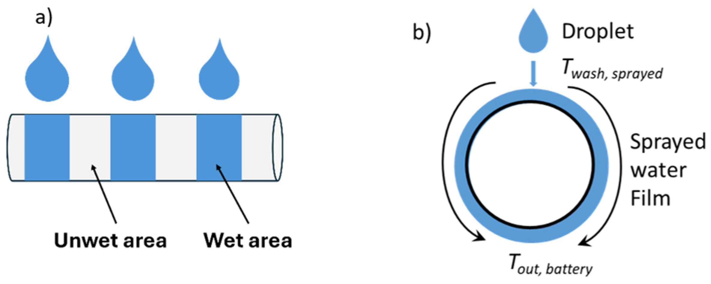
It should be noted that only a fraction of the sprayed water reaches the battery surface (Ef), and even when droplets make contact with the tube surface, they wet only a portion of the battery surface (WR). Figure 2a,b illustrate a simplified schematic of water droplets interacting with the heat exchanger surface (battery). It is assumed that upon contact, the droplets transfer their heat to the liquid inside the battery, reaching a thermal equilibrium. Since the tube wall resistance is considered negligible, the equilibrium temperature is expected to match the temperature of the water inside the battery (Tout, battery).
To calculate ṁs (Equation (4)), the wash pump curve was fitted with a 3rd degree polynomial curve (R2 = 0.999).
s = 0.02 h L 3 0.54 h L 2 8.52 h L + 139 60000 . ρ
where hL (m) is the total head loss.
In both the CaféMate and AP500, the wash water leaves the wash tank, flows into the wash pump, and then is sent to an annulus. The annulus in the wash chamber divides the flow into two parts. Fraction x flows inside the top arm, while fraction 1 − x flows through the bottom arm. The total head loss (Equation (5)) is equal to the summation of hydraulic loss in the top and bottom arms as follows:
h L = h x + h 1 x
where hL is the total head loss. hx and h1−x can be calculated using Equation (6), where “i” could be either “x” for the top arm or “1 − x” for the bottom arm.
h i = f L w d H u 2 2 g + k u 2 2 g + n 2 g ( 1 β 4 ) ( u o C d ) 2
where f is the friction factor; Lw is the length that water flows through an annulus to reach the wash arms (m); dH is the hydrodynamic diameter of the tube (m); k is the loss coefficient for the 90° turns; u is the velocity of the fluid in the tube (m/s); n is the number of orifices on each arm; β is the ratio of orifice diameter to the tube diameter; u0 is the velocity of the jet (m/s); Cd is the discharge coefficient of the orifice, which is provided by the manufacturer; and u0 and u are related to each other using continuity [10].
The friction factor was calculated using Equation (7).
1 f 1 / 2 = 1.8 log 6.9 R e + ϵ / D H 3.7 1.11
where ϵ/DH is the relative pipe roughness (m).
The amount of heat exchanged when a fluid passes over the external surface of a tube is significantly influenced by the fluid’s flow regime. According to Hu and Jakobi, there are six distinct flow regimes for water droplets interacting with an array of horizontal tubes [11,12]. These regimes vary depending on the flow rate of the droplets, with the lowest flow rate referred to as the droplet regime and the highest as the sheet mode. Based on the experimental observations, the flow regime around the heat exchanger during the washing cycle was found to be within the droplet regime.
Equations (8) and (9) were used to evaluate the modified Galileo number (Gamod.) and modified Reynolds number (Remod.).
G a m o d . = ρ σ 3 μ 4 g
R e m o d . = A × G a m o d . B
where σ is water surface tension (N/m); μ is the water viscosity (Pa.s); and A and B are constants dependent on the flow regime (droplet–droplet jet), with values of 0.0785 and 0.2965, respectively [13]. Using the Numod. number, the heat transfer coefficient for the droplets (hD) in Equation (2) can be calculated using Equation (10).
N u m o d . = h D k w υ 2 2 g 1 / 3
where ν and kw are the kinematic viscosity (m2/s) and thermal conductivity of the sprayed water (W/m°C), respectively. By implementing the Remod. and Pr numbers in the empirical relationships, the modified Nusselt number can be calculated using both Equations (11) and (12) [14]. All of the fluid properties used in Equations (11) and (12) were estimated at the average temperature of the Twash, sprayed and Tout, battery. It is important to note that while other relationships exist for estimating Numod., they depend on the geometry of the tube arrays and were, therefore, not considered in this study [11,12,13,14,15].
N u m o d . = 1.1 R e m o d . 1 / 3
N u m o d . = 0.82 R e m o d . 0.22
After completing the sizing and calculating all of the missing parameters (e.g., ṁs, hL, x, hD, L, Ef), the battery was manufactured and installed on the dishwasher.

2.2. Experimental Study

A comprehensive experimental study was conducted to examine the operational nuances of the dishwasher and assess the efficiency improvements achieved by adding the battery to the retrofitted unit. The study involved a simultaneous examination of the entire operational cycle for both the AP500 (with the retrofitted battery) and the CaféMate (without the retrofitted battery) under identical environmental conditions. During this process, water and heat flow distributions were recorded using an array of thermocouples (type: K; range: −200 to 1260 °C; limits of error: −/+ 2.2 °C). Detailed monitoring and data collection were carried out to measure the spray from the rinse and wash arms. This specifically determines the percentage of spray water contacting the tubular surfaces of the battery. This information was essential for understanding the battery’s heat flow distribution and the subsequent simulation study.
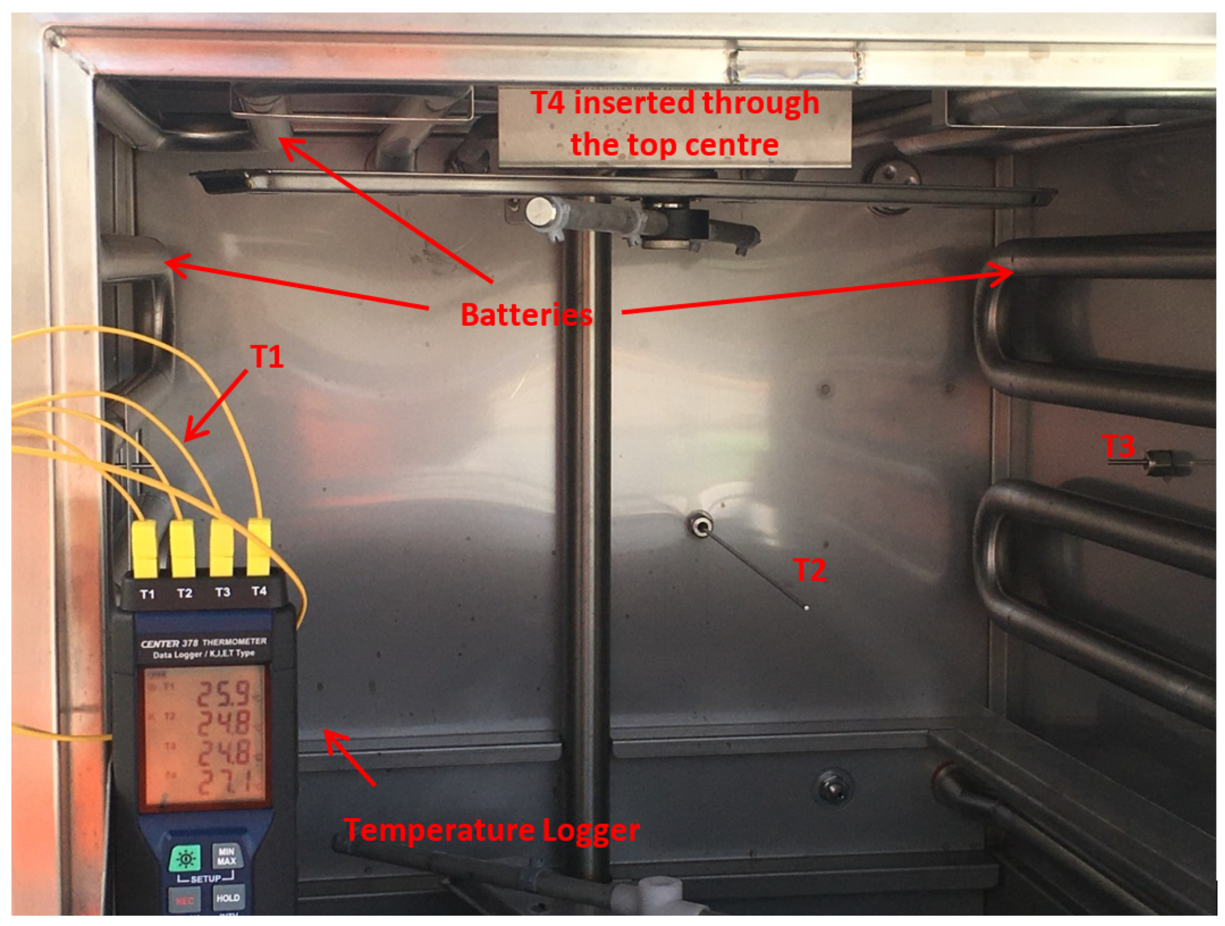
To map the heat distribution inside the dishwasher, 4 thermocouples were strategically placed on the unit at the locations shown in Figure 3.
T1: 5 cm long, located at the left-hand side (LHS) wall.
T2: 30 cm long, located in the middle of the back wall.
T3: 5 cm long, located at the right-hand side (RHS) wall.
T4: 5 cm long, located in the middle of the top of the unit.
The temperature data and patterns collected from the thermocouples were used (in part) to validate the theoretical calculations.
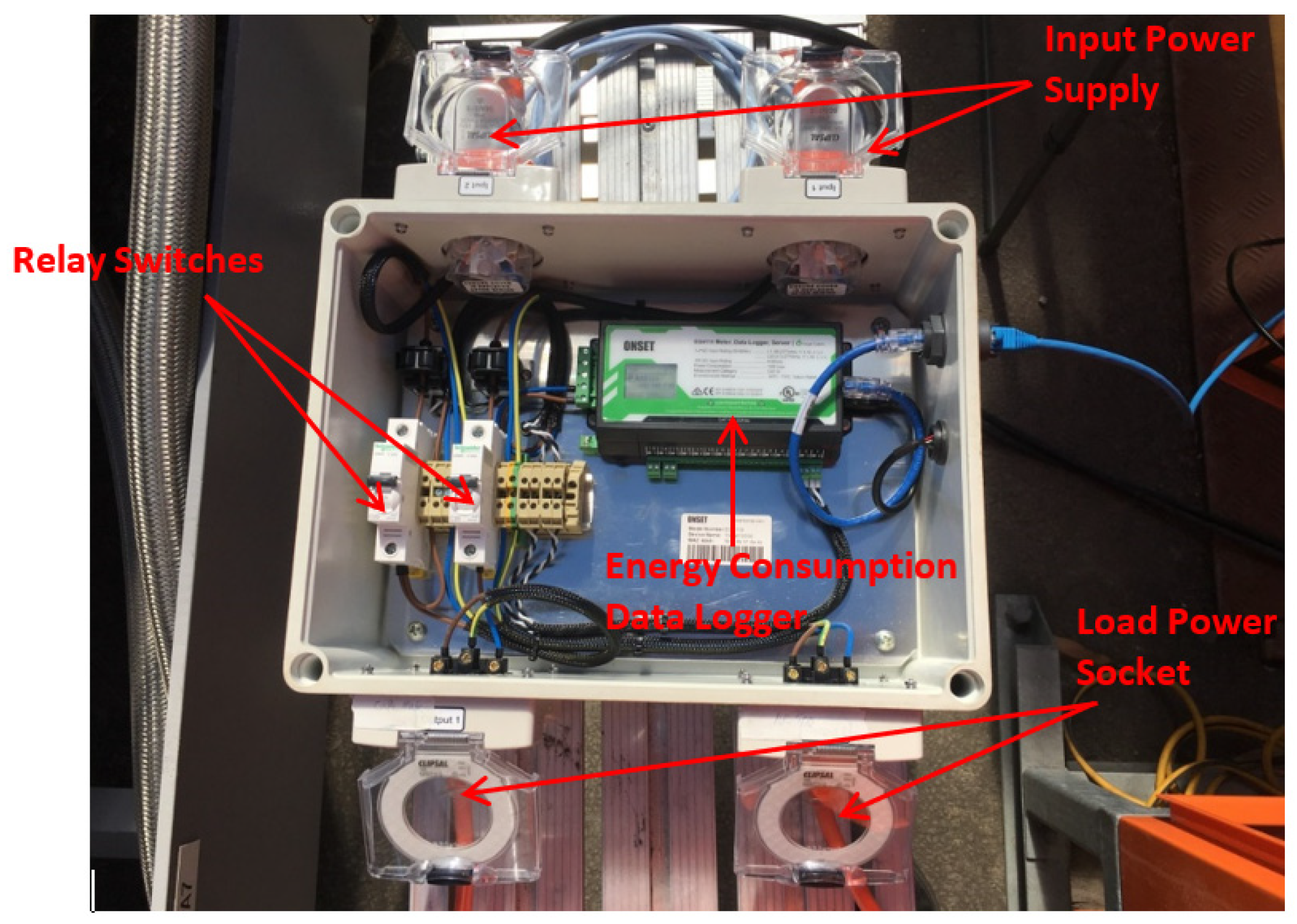
As part of this study, a power usage meter with logging capabilities was designed and fabricated to measure and record the power consumption of the dishwashers during operation (Figure 4).
Both dishwashers were subjected to a range of test scenarios to assess the effectiveness of the battery when using the regular cold-water feed. These scenarios, as outlined in Table 1, were based on the frequency of use, provided by industry data. The power consumption was measured and recorded for each scenario. A one-hour start-up time was applied for each scenario, during which the machine remained idle after being powered on. The waiting time (interval) between the washing cycles was varied, and the door was left open for one minute to allow for loading before each washing cycle.

3. Results and Discussion

To achieve a minimum of a 50% reduction in energy consumption, the Tout, battery value was calculated to be 55 °C using Equation (1). This temperature was used as a benchmark to compare the calculated temperatures using Equations (3)–(12) with the results (considering Twash, sprayed = 62 °C), as tabulated in Table 2.
The data in Table 2, when compared with the temperature calculated using Equation (1), show that the theoretical equations (Equations (2)–(12)) estimate the battery’s internal temperature to exceed 55 °C. This confirms the accuracy of the heat exchanger sizing and demonstrates that the retrofitted dishwasher (AP500) can achieve more than a 50% reduction in energy consumption. Additionally, since the temperature variations in Table 2 are minimal, using the minimum value of WR (20%) allowed for the determination that the water temperature leaving the battery would be at least 56 °C. This value was then used in Equations (3)–(7), and the results are presented in Table 3.
It was estimated that approximately a quarter of the wash water exchanged heat with the battery. The efficiency factor (Ef) was derived from Equation (3), and by substituting the corresponding values, Ef and L provided the relationship presented in Table 3. Using an Ef value of 0.25, the required total tube length for the battery was calculated to be 8.4 m. However, for ease of assembly and cost considerations, the tube length was reduced to 8 m (Ef ≈ 0.24). This 8 m long tube, containing 2.8 L of water, was approximately equivalent to the total volume of water drained from two consecutive operational cycles. The additional water capacity of the battery helped reduce the waiting time between cycles.
To assess the impact of battery location on the energy savings and overall dishwasher performance, the battery was installed in three different positions: left, right, and top of the dishwasher. The configurations and locations are shown in Figure 3. After installation, the temperature of the water exiting the heat exchanger was measured at approximately 54 ± 4 °C, which was close to the predicted values from the theoretical calculations (Table 2).
Seven operational scenarios were identified to examine the performance of the installed battery. The hypothesis was that the energy consumption difference between the AP500 and the CaféMate would increase with the frequency of operation. The electricity usage and power consumption were logged for each scenario. The temperature fluctuations were recorded by thermocouples T1, T2, T3, and T4 and logged by a data logger during operation.
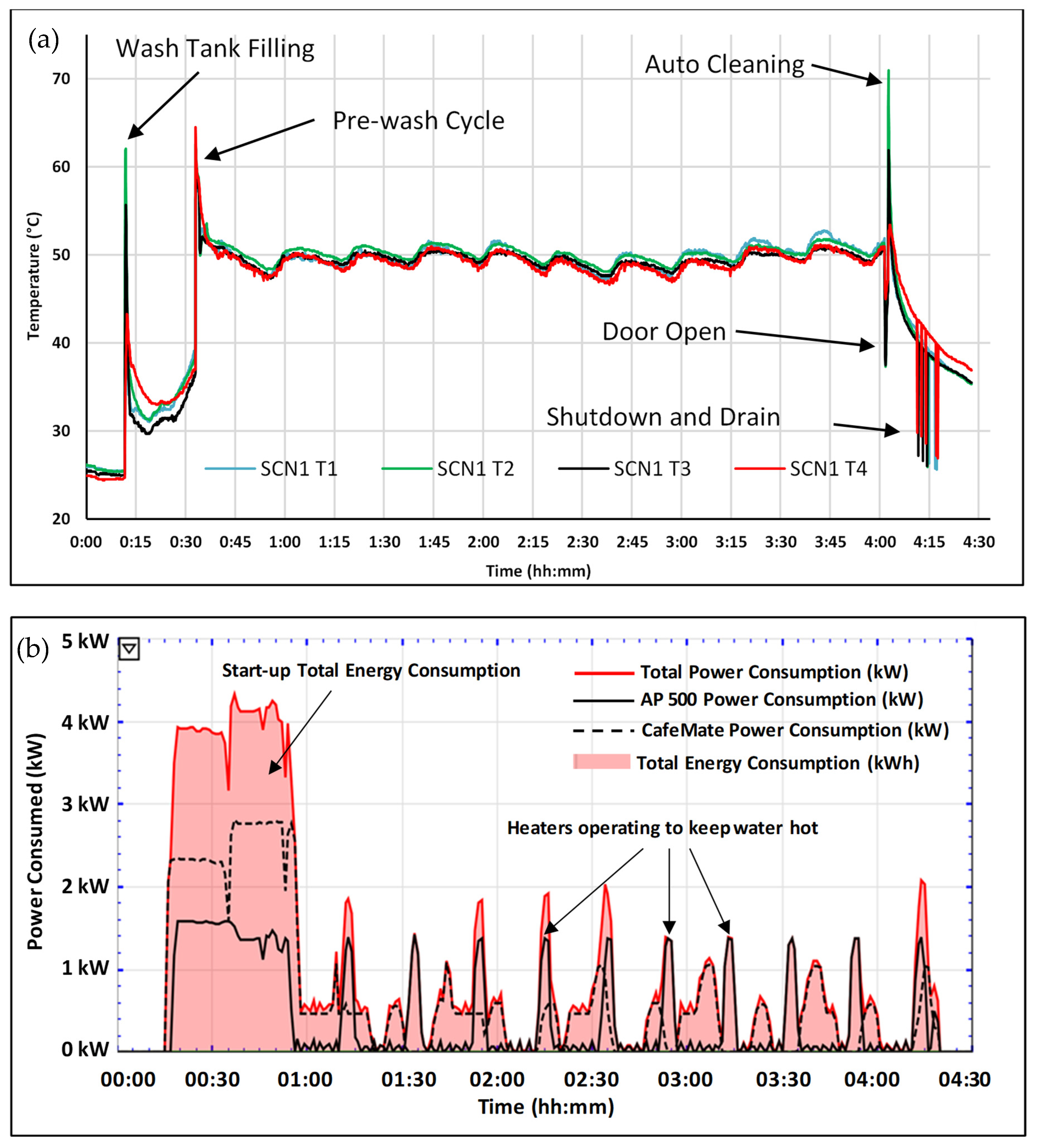
A one-hour start-up time was applied to all scenarios. Scenario 1 considered the situation where the dishwasher remained on throughout the day without any washing cycles, serving as a baseline for the experiments. The subsequent scenarios involved increased washing cycle frequencies. The temperature and power consumption data for Scenario 1 are shown in Figure 5a,b.
As indicated in Figure 5a, the temperature inside the AP500 dishwasher, measured by the four thermocouples, rises from ambient temperature (approximately 25 °C) to around 50 °C after the wash tank filling and pre-wash cycles during the start-up procedure. This increase is primarily due to the wetting of the internal surfaces of the AP500 unit. When no washing cycles are undertaken, the temperature inside the dishwasher decreases. However, a further drop is prevented by heating the circulating water in the boiler, maintaining an average of about 50 °C in the wash tank. This temperature regulation occurs regularly, as shown by the consistent peaks in Figure 5b. After the machine is shut down, the temperature returns to ambient levels.
It is important to note that the sprayed wash water, after leaving the tank, passes through an annulus and heats up to 62 °C by absorbing heat from the hot rinse water (~85 °C) flowing in the central tube.
Figure 5b illustrates the power and energy consumption of the AP500 and CaféMate dishwashers individually. The total energy consumption is represented by the pink shaded area. From the figure, the CaféMate consumes more power during the start-up compared to the AP500, as the wash water and rinse temperatures are raised to approximately 62 °C and 85 °C, respectively. The regular power consumption increases throughout the day as the wash and rinse temperatures are regulated by the increased load on the heating elements. The energy usage for each regulation cycle remains relatively constant.
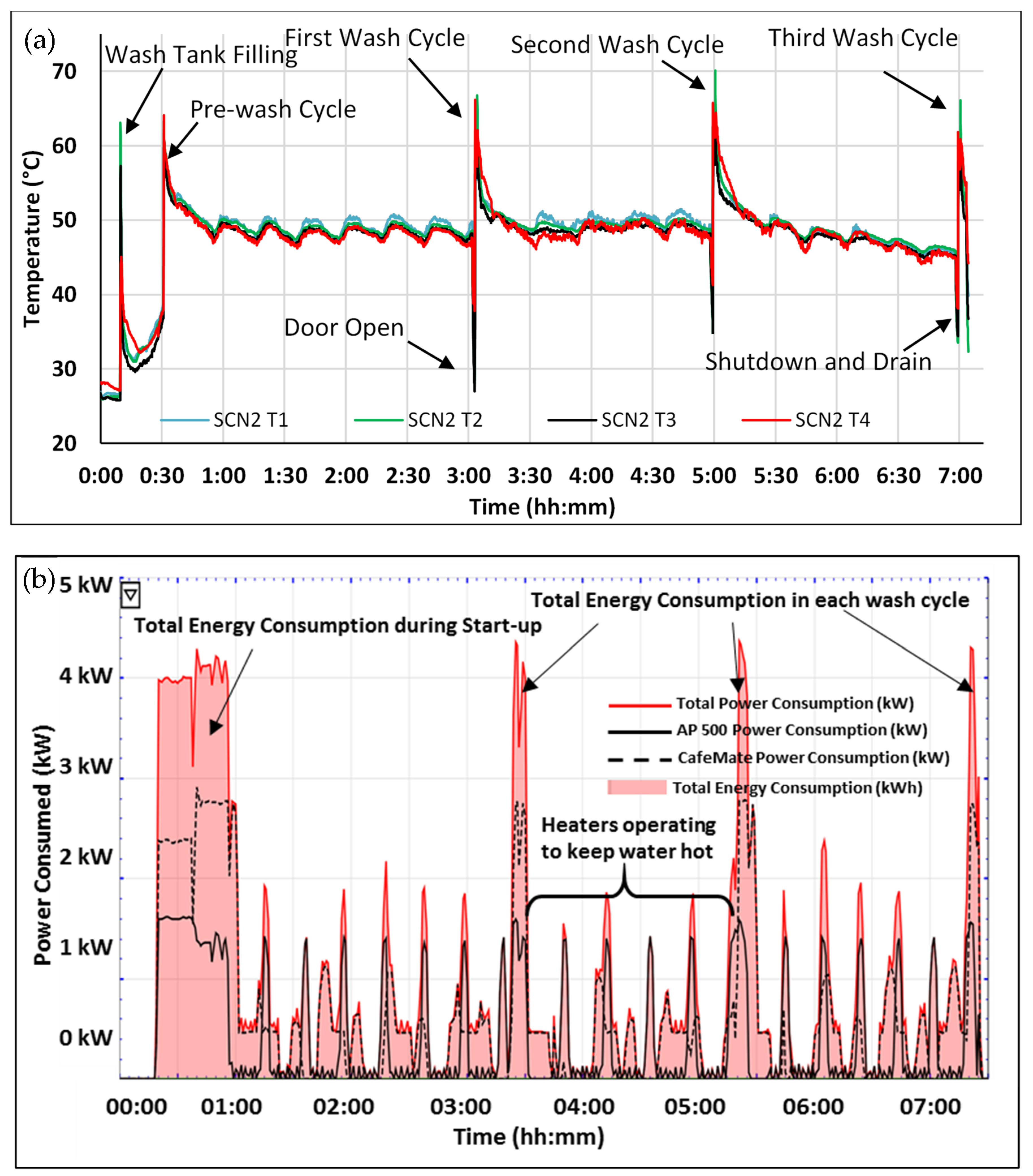
Figure 6 presents the experimental results for Scenario 2, which involves a one-hour start-up period followed by three wash cycles with two-hour waiting times between cycles. The dishwasher door was left open for one minute before the start of each wash cycle. This accounts for the temperature drop shown in Figure 6a, as indicated by the thermocouples in the AP500.
The three peaks in Figure 6b correspond to the increase in power consumption following the completion of each wash cycle. A more pronounced rise in power consumption is observed for the CaféMate after each cycle, clearly demonstrating the impact of the battery in reducing power consumption in the AP500.
The experimental results for the other scenarios (i.e., Scenarios 3–7) followed a similar pattern, as illustrated in Figure 5 and Figure 6.
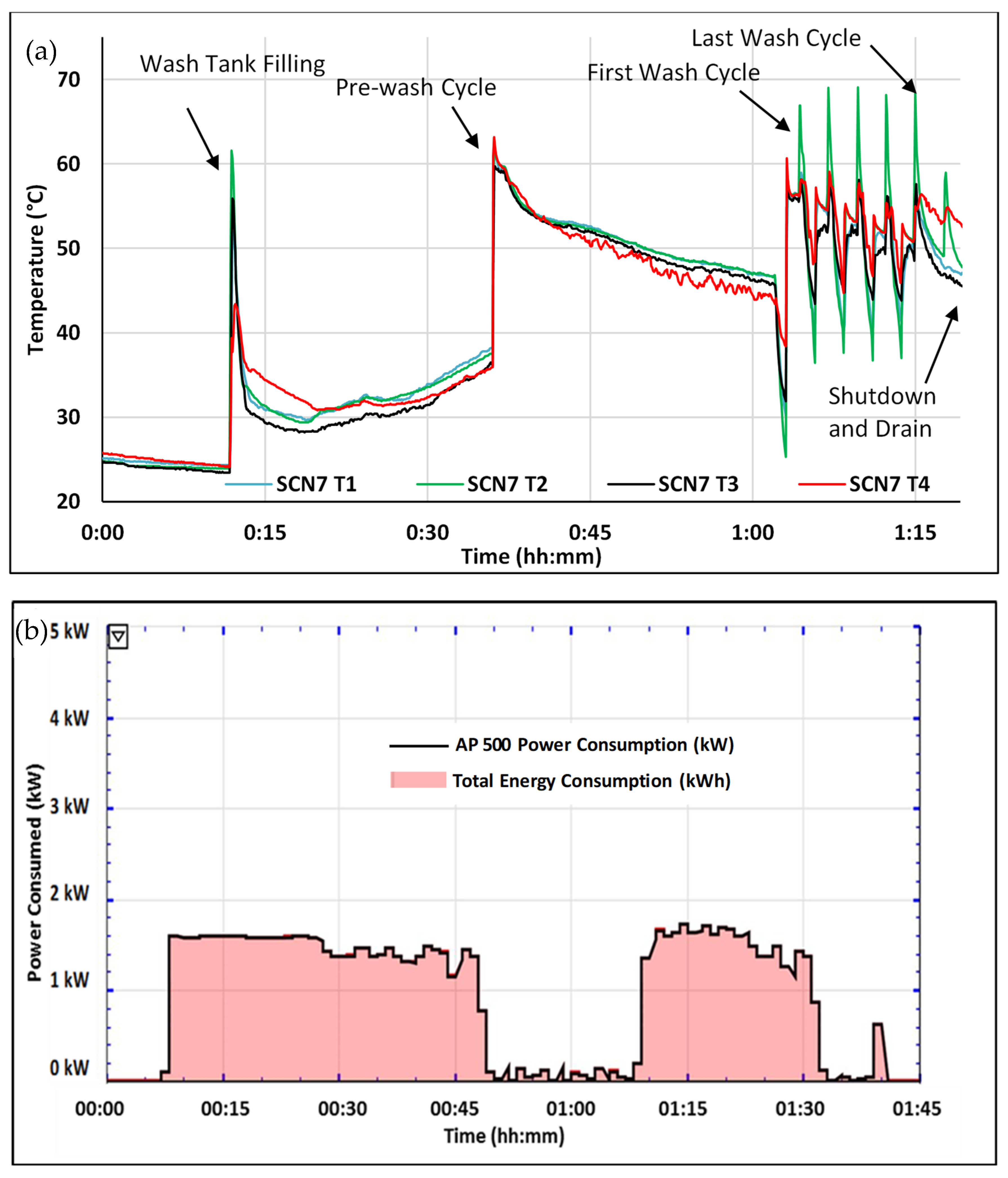
Results for Scenarios 6 (5 min waiting time between five wash cycles) and 7 (no interval between five wash cycles) are shown in Figure 7 and Figure 8, respectively.
The results from Scenarios 6 and 7 clearly show that the additional heating load on the heating elements required to regulate the wash water and rinse temperatures is absent. As a result, power consumption occurs solely during the washing cycles. This suggests that for optimal operation of both machines, the time between wash cycles should not exceed 15 min. Consecutive wash cycles were not feasible for the CaféMate due to a significant drop in wash water temperature. As a result, there was insufficient time for the CaféMate to reach the target temperatures of approximately 60 °C for the wash cycle and 80 °C for the rinse cycle. The total energy consumption for each operational scenario of both the AP500 and CaféMate is shown in Figure 9.
As shown in Figure 9, the retrofitted AP500 consumes significantly less energy during operation. The average energy consumption for the start-up and wash cycles across all scenarios was found to be 1.98 kWh and 0.4 kWh for the CaféMate compared to 1.06 kWh and 0.18 kWh for the AP500, respectively. The data also indicate the presence of an optimal waiting time between wash cycles. The more frequent the wash cycles throughout the day, the lower the overall energy consumption (with wash intervals not exceeding 15 min between cycles).
The average energy savings relative to the CaféMate are summarized in Table 4. The greatest total energy savings compared to the CaféMate were achieved in Scenarios 5 and 6. The cost savings per cycle have been recalculated using the assumption that the AP500 consumes 1.8 kWh during operation. The total daily savings are based on the number of cycles completed in 8 h, assuming that the cycles are being performed continuously.

4. Conclusions

A comprehensive investigation was undertaken to evaluate various strategies aimed at reducing the energy consumption of a typical commercial dishwasher. The most effective approach for achieving nominal energy savings was identified, and the potential energy savings achievable through a retrofit were quantified. These savings were shown to be effectively integrable into the original design of the dishwasher. A heat exchanger was conceptualized, designed, and retrofitted into an AP500 model dishwasher. Energy consumption was reduced by nearly 50% in the retrofitted unit when tested under multiple operational scenarios compared to an equivalent unmodified unit.
Further experimental evaluations indicated that energy savings in commercial dishwashers can be optimized by limiting the waiting period between wash cycles to no more than 15 min. The substantial impact of both retrofitting and cycle optimization on improving the energy efficiency in commercial dishwashing operations was thus demonstrated.

Author Contributions

Conceptualization, J.Z. and A.S.; methodology, J.Z., A.S. and B.M.; formal analysis, A.S. and J.Z.; investigation, J.Z., A.S. and G.G.; resources, G.G. and B.M.; data curation, A.S. and J.Z.; writing—original draft preparation, J.Z. and A.S.; writing—review and editing, G.G. and B.M.; supervision, B.M. and G.G.; project administration, G.G. and B.M. All authors have read and agreed to the published version of the manuscript.

Funding

This research received no external funding.

Data Availability Statement

The data presented in this study are available within the article.

Acknowledgments

This project was a collaboration between the University of Newcastle and Norris Industries, award-winning manufacturers of commercial dishwashers. The authors also thank the Newcastle Institute of Energy and Resources for their contributions.

Conflicts of Interest

The authors declare no conflict of interest.

Nomenclature

Cddischarge coefficient of the orifice (0.8)
cpheat capacity of water (Kj/kg °C)
dHhydrodynamic diameter of the tube (m)
diinside tube diameter (m)
dooutside battery diameter (m)
Effraction of sprayed water that reaches the battery surface (25%)
ffriction factor
hDconvective heat transfer coefficient for droplets (W/m2°C)
hLtotal head loss (m)
kloss coefficient for the 90° turns (0.3)
Kwthermal conductivity of sprayed water (W/m°C)
Llength of the battery (m)
Lwtube length that water flows through to reach the wash arms (m)
sflow rate of sprayed water (kg/s)
nnumber of orifices on each arm (8)
SRsaving ratio
Tin,freshwatertemperature of cold inlet water (°C)
Tout,batterywater temperature inside the battery as well as the sprayed water temperature leaving the battery surface (°C)
Tout,boilertemperature of water leaving the boiler (°C)
Tw/ retro.temperature difference with retrofit (30 °C)
Tw/o retro.temperature difference without retrofit (60 °C)
twashduration of the wash cycle (60 s)
Twash, sprayedtemperature of the sprayed water (62 ± 2 °C)
uvelocity of the fluid in the tube (m/s)
uovelocity of the jet (m/s)
WRwetting ratio (~20–30%)
xfraction related to head loss in the top arm
1 − xfraction related to head loss in the bottom arm
βratio of orifice diameter to the tube diameter
ϵaverage pipe roughness (m)
μviscosity of sprayed water (Pa.s)
νkinematic viscosity of sprayed water (m2/s)
ρwater density (kg/m3)
σsurface tension of sprayed water (N/m)

References

  1. Persson, T. Dishwasher and washing machine heated by a hot water circulation loop. Appl. Therm. Eng. 2007, 27, 120–128. [Google Scholar] [CrossRef]
  2. Caskey, S.L.; Groll, E.A. Modelica household dishwater model with external heat loop. In Proceedings of the 5th International High Performance Buildings Conference at Purdue, West Lafayette, IN, USA, 9–12 July 2018; Volume 3692, p. 2. [Google Scholar]
  3. Zhang, Z.; Zhang, J.; Yuan, H.; Chen, G.; Mei, N. Performance improvement of the electric water heater by a waste heat recovery method with the thermoelectric effect. Appl. Therm. Eng. 2023, 222, 119914. [Google Scholar] [CrossRef]
  4. Piotrowska, B.; Stys, D. Variant analysis of financial and energy efficiency of the heat recovery system and domestic hot water preparation for a single-family building: The case of Poland. J. Build. Eng. 2023, 65, 105769. [Google Scholar] [CrossRef]
  5. Kordana-Obuch, S.; Starzec, M. Horizontal shower heat exchanger as an effective domestic hot water heating alternative. Energies 2022, 15, 4829. [Google Scholar] [CrossRef]
  6. Selimi, S.; Eljetlawi, I. The experimental study of thermal energy recovery from shower greywater. Energy Sources Part A Recovery Util. Environ. Eff. 2021, 43, 23. [Google Scholar]
  7. Salameh, W.; Faraj, J.; Harika, E.; Murr, R.; Khaled, M. On the optimization of electrical water heaters: Modelling simulations and experimentation. Energies 2021, 14, 3912. [Google Scholar] [CrossRef]
  8. Caskey, S.L.; Groll, E.A. Modelica analysis of thermally connected residential appliances. In Proceedings of the 5th International High Performance Buildings Conference at Purdue, West Lafayette, IN, USA, 9–12 July 2018; Volume 3693, p. 1. [Google Scholar]
  9. Anim-Mensah, A.R.; Waechter, B.J. Warewasher with drain water tempering system with energy recovery using plate heat exchangers. U.S. Patent No. 9,986,886, 5 June 2018. [Google Scholar]
  10. White, F. Fluid Mechanics; McGraw-Hill Companies, Inc.: New York, NY, USA, 2011. [Google Scholar]
  11. Hu, X.; Jacobi, A.M. Departure-Site Spacing for Liquid Droplets and Jets Falling in Thin-Film Heat Exchangers; The University of Illinois at Urbana-Champaign: Champaign, IL, USA, 1997. [Google Scholar]
  12. Hu, X.; Jacobi, A.M. The intertube falling film: Part 2—Mode effects on sensible heat transfer to a falling liquid film. J. Heat transfer 1996, 118, 626–633. [Google Scholar] [CrossRef]
  13. Snajdarek, L.; Kracik, P.; Lisy, M.; Pospisil, J. The falling liquid film heat transfer outside horizontal tubes relation. Adv. Fluid Mech. Heat Mass Transf. 2012, 3, 3. [Google Scholar]
  14. Jafar, F.A. Flow Fields and Heat Transfer of Liquid Falling Film on Horizontal Cylinders. Ph.D. Thesis, Victoria University, Melbourne, Australia, 2011. [Google Scholar]
  15. Jeong, S.; Garimella, S. Falling-film and droplet mode heat and mass transfer in a horizontal tube LiBr/water absorber. Int. J. Heat Mass Transf. 2002, 45, 1445–1458. [Google Scholar] [CrossRef]
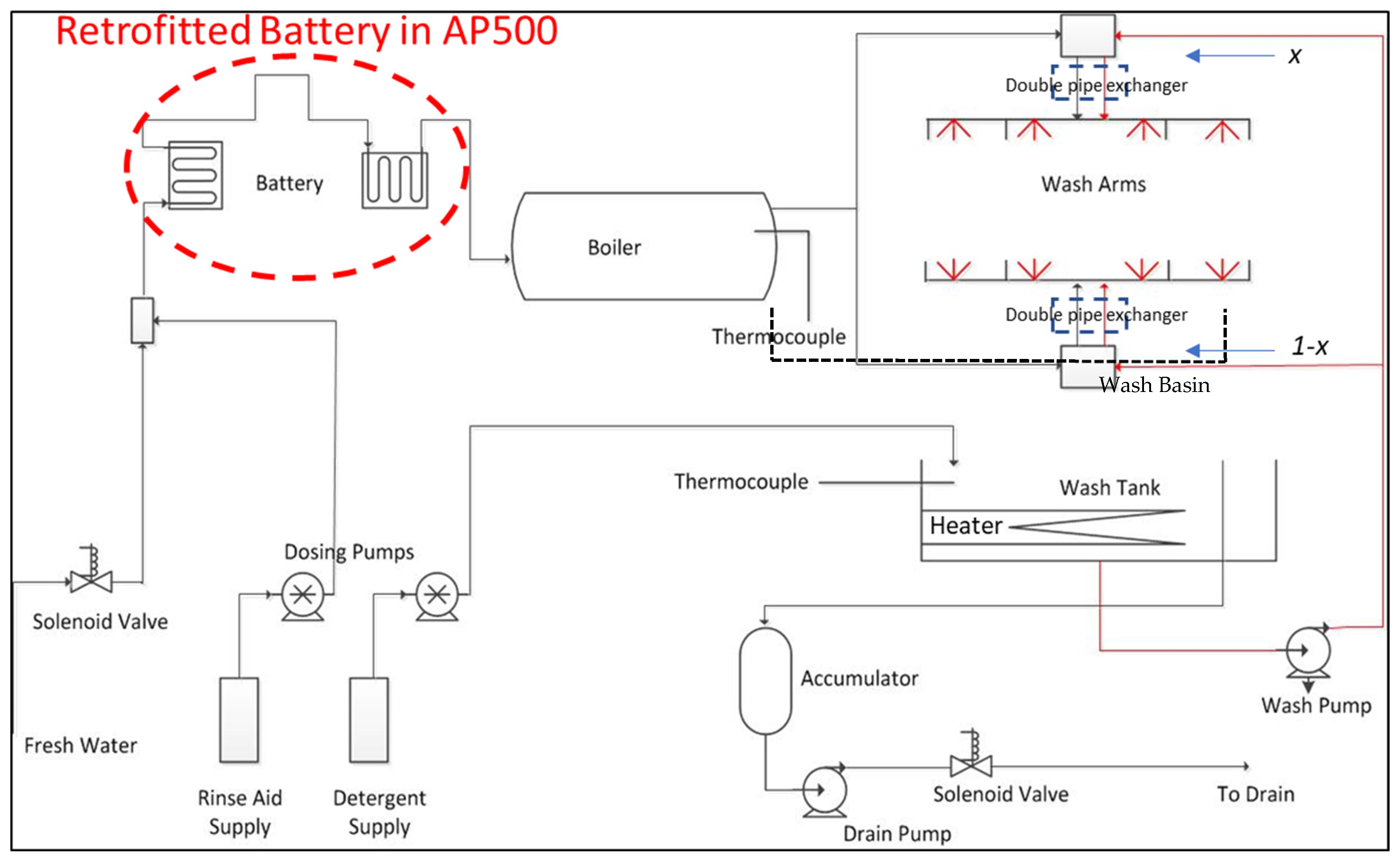
Figure 1. P and ID schematics of the CaféMate and AP500. x and 1 − x are the fractions of water flowing through the top and bottom shower arms. Note that the battery is installed within the wash chamber, which is not indicated here.
Energies 18 02338 g001
Figure 2. Schematic view of droplets interacting with the battery surface: (a) side view and (b) front view.
Energies 18 02338 g002
Figure 3. Internal image of the modified dishwasher, including the locations of the temperature probes (T1 to T4) and the batteries (heat exchanging pipes) on the sidewalls and the ceiling.
Energies 18 02338 g003
Figure 4. Energy consumption data logger box.
Energies 18 02338 g004
Figure 5. Experimental results for Scenario 1. (a) Temperature profiles of the AP500. (b) Power and energy consumption of AP500 and CaféMate.
Energies 18 02338 g005
Figure 6. Experimental results for Scenario 2. (a) Temperature profiles of AP500. (b) Power and energy consumption of the AP500 and CaféMate.
Energies 18 02338 g006
Figure 7. Experimental results for Scenario 6. (a) Temperature profiles of the AP500. (b) Power and energy consumption of the AP500 and CaféMate.
Energies 18 02338 g007
Figure 8. Experimental results for Scenario 7. (a) Temperature profiles of the AP500. (b) Power and energy consumption of the AP500.
Energies 18 02338 g008
Figure 9. Total energy consumption of the AP500 and CaféMate for all scenarios.
Energies 18 02338 g009
Table 1. Operation scenarios.
ScenariosStart-up (min)CYCLE-ICYCLE-IICYCLE-IIICYCLE-IVCYCLE-V
Waiting time (min)Loading (min)Rinse/Wash (min)Waiting time (min)Loading (min)Rinse/Wash (min)Waiting time (min)Loading (min)Rinse/Wash (min)Waiting time (min)Loading (min)Rinse/Wash (min)Waiting time (min)Loading (min)Rinse/Wash (min)
Scenario 1601800DefaultNANANANANANANANANANANANA
Scenario 2601201Default1201Default1201DefaultNANANANANANA
Scenario 360601Default601Default601Default601DefaultNANANA
Scenario 460301Default301Default301Default301DefaultNANANA
Scenario 560151Default151Default151Default151Default151Default
Scenario 66051Default51Default51Default51Default51Default
Scenario 76001Default01Default01Default01Default01Default
Table 2. Results for Tout, battery using Equations (11) and (12) for different WRs.
WRTout, battery °C (Equation (11))Tout, battery °C (Equation (12))
2056.0558.8
2558.260.2
3059.661
Table 3. Calculated values for the unknown parameters for Equations (3)–(7).
ParameterValue/EquationDescription
x0.49fraction of sprayed water flowing in the top arm
hL (m)6.1total head loss
s (kg/s)1mass flow rate of sprayed wash water
L (m) 33.8Efrelationship between L and Ef (Equation (3))
Table 4. Total energy savings relative to CaféMate operating with a cold-water feed (electricity cost: 35 cents/kWh).
ScenariosTotal Energy SavingsAverage Energy Savings per Wash CycleCost Savings per Cycle ($)
137%00
238%53%0.14
341%46%0.12
444%41%0.10
549%49%0.17
648%46%0.15
7--
Disclaimer/Publisher’s Note: The statements, opinions and data contained in all publications are solely those of the individual author(s) and contributor(s) and not of MDPI and/or the editor(s). MDPI and/or the editor(s) disclaim responsibility for any injury to people or property resulting from any ideas, methods, instructions or products referred to in the content.