1. Introduction
In the contemporary energy landscape, lithium-ion batteries (LIBs) are integral to the functioning of electric vehicles and energy storage systems. These batteries are distinguished by their high energy density, efficiency, extended cycle life, and environmentally friendly characteristics [
1]. However, research has demonstrated that the temperature significantly impacts battery performance, internal resistance, and longevity [
2,
3,
4]. Surpassing a specific temperature threshold can lead to a reduction in operational efficiency [
5]. Elevated temperatures may trigger side reactions that can result in thermal runaway events and associated safety risks [
6,
7]. Conversely, at lower temperatures, there is a marked decrease in both the discharge capacity and power output of these batteries [
8,
9,
10]. Extremely low temperatures can cause irreversible capacity loss and increase safety concerns [
11,
12]. For high-power-density LIBs, these thermal-related issues are even more pronounced. Their high power density implies that a larger quantity of heat is generated per unit volume during the charge and discharge processes, leading to a rapid temperature increase and making the temperature distribution non-uniform within the battery. Moreover, the uneven heat generation in different parts of the battery presents additional challenges for thermal management. The intricate internal structure of high-power-density batteries further intensifies the difficulty of attaining a uniform temperature distribution. Consequently, effective thermal management for LIBs is of the utmost importance; this challenge is especially evident for high-power variants, which are characterized by their less-than-ideal thermal properties.
Bandhauer et al. [
13] and Wu et al. [
14] have conducted extensive reviews addressing the thermal management challenges associated with LIBs. Effective thermal management is essential for battery applications. However, the current strategies frequently fall short in meeting the requirements. Due to the inherent limitations of individual cells, multiple cells are interconnected to form modules, which necessitates systematic oversight. The performance of a module is governed by the “barrel principle”, which underscores the importance of maintaining temperature uniformity, with a maximum allowable difference of ≤5 °C [
15]. Significant temperature variations can negatively impact both the lifespan and safety of batteries [
16], thereby underscoring the need for further research in this area. Standard cooling methods include air cooling, liquid cooling, phase change materials (PCM) [
17], and various combinations of these techniques [
18]. Air cooling is noted for its simplicity and cost-effectiveness. Nevertheless, it is often inadequate for scenarios involving high power dissipation. PCM cooling has its limitations, including low thermal conductivity and a restricted latent heat capacity. In contrast, liquid cooling demonstrates high efficiency and has emerged as the preferred option for electric vehicle (EV) applications and energy storage modules [
19]. Liquid cooling can be implemented in direct configurations, where batteries are immersed in a coolant [
20], or in indirect configurations that utilize cold plates or tubes.
A substantial number of studies have been conducted in this field. Bahiraei et al. [
21] optimized battery cooling systems for hybrid vehicles. Xia et al. [
22] enhanced liquid cooling structures; Shen et al. [
23] proposed an innovative direct cooling device. Worwood et al. [
24] focused on optimizing heat pipe-based cylindrical battery coolers. Zhang et al. [
25] improved the heat transfer mechanisms. Bandhauer et al. [
26] investigated microchannel phase change solutions. Patil et al. [
27] examined U-shaped microchannel cold plates. Deng et al. [
28] analyzed flow channel configurations within serpentine cold plates. However, there are few reports on the thermal management of low-voltage and high-power battery modules.
This study presents a comprehensive review of the electrothermal characteristics of high-power pouch batteries as documented in the existing literature. To comply with stringent ambient conditions (45 °C, module temperature ≤60 °C, cell-to-cell temperature difference <5 °C, and cell surface temperature difference <2 °C), a U-shaped serpentine liquid cooling structure is designed for a 48 V high-power-density battery module intended for start–stop applications. The designed U-shaped “bathtub-type” cooling structure is an innovation in high-power-density battery thermal management. Unlike traditional designs, it maximizes the use of the battery’s surrounding 3D space, enabling extensive surface cooling. The U shape, by creating a more efficient heat transfer route, enables the coolant to dissipate heat from multiple battery surfaces. This structure not only augments the cooling efficiency but also optimizes the temperature uniformity across the battery module, which is essential in maintaining battery performance and safety. A fluid–solid coupling simulation model, along with a testing environment for the module’s liquid cooling system, is established. Simulations and experiments are performed under realistic conditions, including extreme rate discharge at 40 C and 10 C pulse charging/discharging cycles. Through the analysis of the temperature distribution and evolution within the battery module, this research analyzes the heat dissipation mechanisms in high-power-density lithium-ion modules. The results provide a solid theoretical and engineering foundation for the development of high-power, fast-charging, and ultrafast-charging battery modules.
2. Thermal Transfer Mechanisms of High-Power Battery Modules
During the charging and discharging processes of LIBs, temperature fluctuations occur due to heat generation and transfer mechanisms. Understanding these heat transfer processes is essential in designing effective thermal management systems in battery modules. Pouch-type LIBs are constructed by stacking individual cell units. In a simplified analysis, complex side reactions are neglected, allowing the battery to be treated as a uniform entity with respect to heat dissipation. During the charging and discharging cycles of LIBs, electrode reactions involve entropy changes [
29]. Meanwhile, inherent ohmic resistance and kinetic barriers to charge and mass transfer emerge. Coupled with active material migration under the electric field, these factors alter the battery’s internal resistance, converting some input energy into heat and increasing the energy loss. The Bernardi equation is commonly utilized to quantify this thermal generation within batteries. The heat generation rate
Qg is calculated as follows:
where
I is the operating current (A);
U is the operating voltage (V);
is the open-circuit voltage (V);
T is the battery temperature (K); and
is the entropic coefficient (V/K).
Heat dissipation (
) encompasses three primary mechanisms: conduction, convection, and radiation. According to concentrated solution theory, during the charging and discharging processes of a battery, the flow of the electrolyte is minimal, leading to the assumption that electrolyte convection is negligible. Therefore, heat transfer within the battery predominantly occurs through conduction. The rate of heat conduction is determined by Fourier’s law as follows:
where
is the material thermal conductivity (W/(m·K));
is the cross-sectional area perpendicular to heat flow (m
2); and
is the temperature gradient (K/m).
The heat transfer by convection between the battery and the surrounding fluids (e.g., air or coolant) is determined using Newton’s law of cooling:
where
h is the convective heat transfer coefficient (W/(m
2·K));
is the convective heat transfer area (m
2); and
is the temperature difference between the battery module surface and the fluid (K).
A comprehensive understanding of the thermal transfer mechanisms in high-power battery modules establishes a theoretical foundation for the design of liquid cooling systems and simulation models. Analyzing heat generation and dissipation is essential in optimizing the thermal management systems of battery modules, thereby ensuring that the batteries operate within an optimal temperature range. This optimization not only enhances the performance but also extends the lifespan of the batteries and improves their safety.
3. Structural Design and Modeling of Battery Modules
The thermal design of battery modules encompasses two primary aspects: heat conduction within the cells and the dissipation of heat from the module. A pouch-laminated battery can be conceptualized as an anisotropic conducting cuboid, with its properties characterized along the length (x), width (y), and thickness (z) directions. In practical analyses, the thin aluminum–plastic film enclosure is frequently either disregarded or represented as a thermal resistance element. Heat conduction in a pouch battery adheres to Fourier’s law through Equation (4) as follows:
where
,
, and
are the battery’s thermal conductivities in the length, width, and thickness directions, and
is the cell volume. The pouch-laminated batteries under investigation exhibit significantly high thermal resistance in the thickness direction, approximately 45 times greater than that in other orientations, which substantially impedes heat conduction. However, these batteries possess a considerable heat dissipation area in the thickness (z) direction, measuring 162 mm × 228 mm. In contrast, the corresponding regions in the length (x) and width (y) directions are considerably smaller, at 4.5 mm × 228 mm and 4.5 mm × 162 mm, respectively. These characteristics complicate the dissipation of heat generated during the charging and discharging processes, thereby jeopardizing the efficient and stable operation of the battery. Consequently, a primary objective in the design of the module structure is to facilitate the effective dissipation of heat produced by the battery.
3.1. Module Structure Design
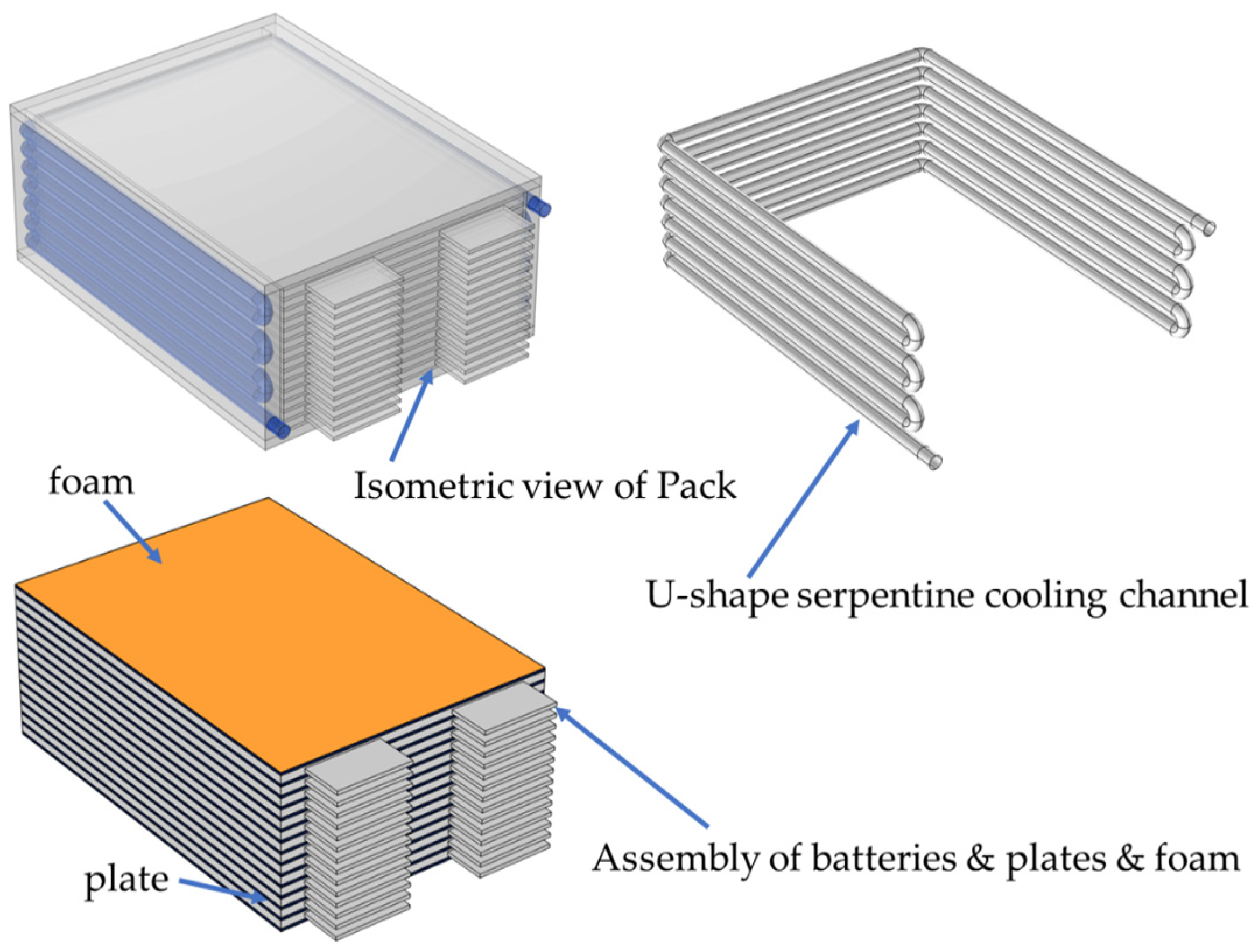
In consideration of the structural and thermal characteristics of pouch cells, a 48 V high-power battery module has been developed, incorporating an integrated cooling system. This system features a U-shaped cooling chamber that houses an aluminum heat-conducting plate. Aluminum has been selected due to its lightweight nature and effective thermal conductivity. This material facilitates the uniform distribution of the temperature across the cell plane, enables rapid heat transfer, and enhances the structural integrity. The aluminum heat-conducting plate, which is 1~2 mm in thickness and coated with a thermally conductive adhesive on both surfaces, is precisely sized to fit the battery and ensures tight contact. The adhesive serves to minimize contact thermal resistance that may arise from inadequate fitting and air gaps. Heat generated by the cells is conducted to the U-shaped aluminum cooling cavity and subsequently dissipated through the flow of the coolant within the cavity of the plate. The structural design is illustrated in
Figure 1, and the dimensions of each component of the battery module are shown in
Table 1.
The battery module comprises five essential components: batteries, heat-conducting plates, thermal silica gel or foam, a U-shaped cooling cavity, and cooling channels. It is constructed by connecting 14 lithium–iron–phosphate pouch batteries in series. Within the U-shaped cooling cavity, 13 aluminum heat-conducting plates are strategically arranged, alternating with the batteries. The foam within the U-cavity serves to provide both insulation and cushioning. A serpentine cooling channel integrated into the U-cavity facilitates a three-sided immersion-type liquid cooling system for the sides of the batteries (excluding the tab side), with a diameter of 8 mm. During charging and discharging, heat is first transferred from the battery to the heat-conducting plate through conduction. The cooling plate, equipped with the serpentine channel, conducts and exchanges heat, while the coolant and the naturally convecting air effectively remove the heat through convection. This design addresses the heat dissipation challenges associated with pouch cells, and the multi-faceted heat dissipation system is anticipated to enhance the module’s overall heat dissipation efficiency.
3.2. Module Modeling
In the field of research on battery thermal management, computational fluid dynamics (CFD) tools have evolved into essential resources with extensive application in many studies [
30,
31,
32]. The battery module model developed within this research framework has been seamlessly integrated with COMSOL 6.0 Multiphysics, as elaborated below.
Materials and parameter definition: It is essential to define the materials used in the module precisely and to input key parameters, as
Table 2 shows.
Heat source definition: The definition of heat sources in batteries should be strictly delineated for both the tab and cell components in accordance with Equation (1). The battery heat dissipation data are obtained by fitting the test results, and the value is 456,000 W/m3 at 40 C and 29,007 W/m3 at 10 C, which is set to be evenly distributed in the battery cells, as a constant, ensuring that it does not conflict with the intention of the simulations to assess the cooling ability of the designed system.
Boundary condition setting: The boundary condition of the battery pack is established based on the initial ambient temperature under natural convection conditions. To accurately model the heat transfer at the boundary, the convection coefficient is set to 5 W/(m2·K) considering the liquid cooling system’s airflow limitations. Thermal radiation is not considered at present. The initial temperatures of the ambient environment, coolant, and battery module are all set at 45 °C. For the inlet boundary, the mass flow rate or other appropriate parameters can be adaptively selected as control variables according to the research requirements. The outlet is set as a 0 Pa standard pressure boundary for an open flow environment. In coolant flow studies, a k-ε turbulence model is employed to construct a high-precision numerical framework after the Reynolds number has been calculated. Wall functions are enabled to improve the near-wall calculation accuracy, and the no-slip wall condition is enforced to meet fluid dynamics principles.
Mesh: The model utilizes a physically driven adaptive meshing strategy, where intelligent algorithms are harnessed to optimize both the mesh properties and the meshing process. The mesh density is adjusted dynamically according to physical quantity gradients, thereby refining high-gradient areas such as fluid domain walls. The final mesh comprises 2.4 × 10⁷ elements, predominantly tetrahedral in shape, and, to enhance the fitting accuracy in complex geometries, prismatic elements are added. Key parameters, which play a crucial role in determining the mesh quality, include a maximum element size of 26.5 mm and a minimum element size of 4.77 mm, among others. The boundary layer consists of five prismatic layers, where the first layer, with a thickness of 0.1 mm, is deliberately set to ensure the accurate representation of the near-wall flow characteristics, and it has a thickness factor of 2.5. Sharp corners are refined through geometric recognition techniques, which effectively strike a balance between computational efficiency and accuracy, ensuring that the simulation results are both reliable and computationally feasible.
Charging/discharging settings: Configure the charging and discharging rates and calculation duration. Set the calculation step to 1 s for a balance between accuracy and efficiency, enabling the thorough simulation of the thermal performance under various conditions.
3.3. Grid Independence Analysis
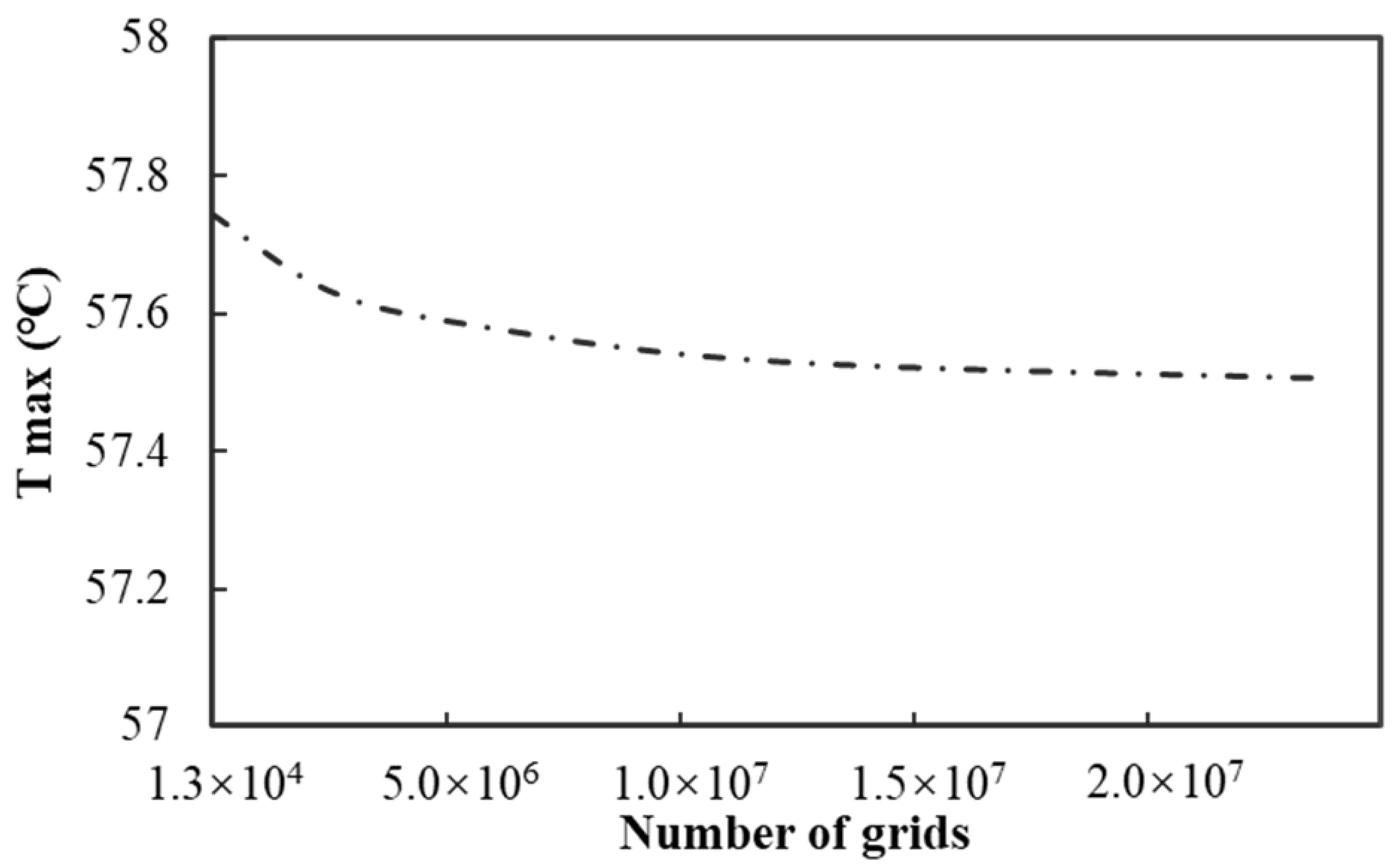
Before applying the model, it is essential to conduct a grid independence analysis. Five different types of grids are employed to mesh the model, and the number of grids is set within the range of 1.3 × 10
4 to 2.4 × 10
7. Subsequently, the simulation conditions are set as follows: the ambient temperature is kept constant at 45 °C, water is selected as the coolant, the flow rate of the coolant is maintained at 12 g/s, the battery discharge rate is set at 40 C, and the discharge duration is 90 s. The simulation experiment is carried out under these conditions, and the maximum temperature of the battery is taken as the key evaluation index. As shown in
Figure 2, the variation in the calculation results is extremely small, and the resulting errors are within a reasonable and acceptable range.
Taking both the calculation accuracy and cost factors into comprehensive consideration, the meshing scheme with a grid number of 2.4 × 10⁷ is finally determined.
4. Battery Module Simulation Calculation and Result Analysis
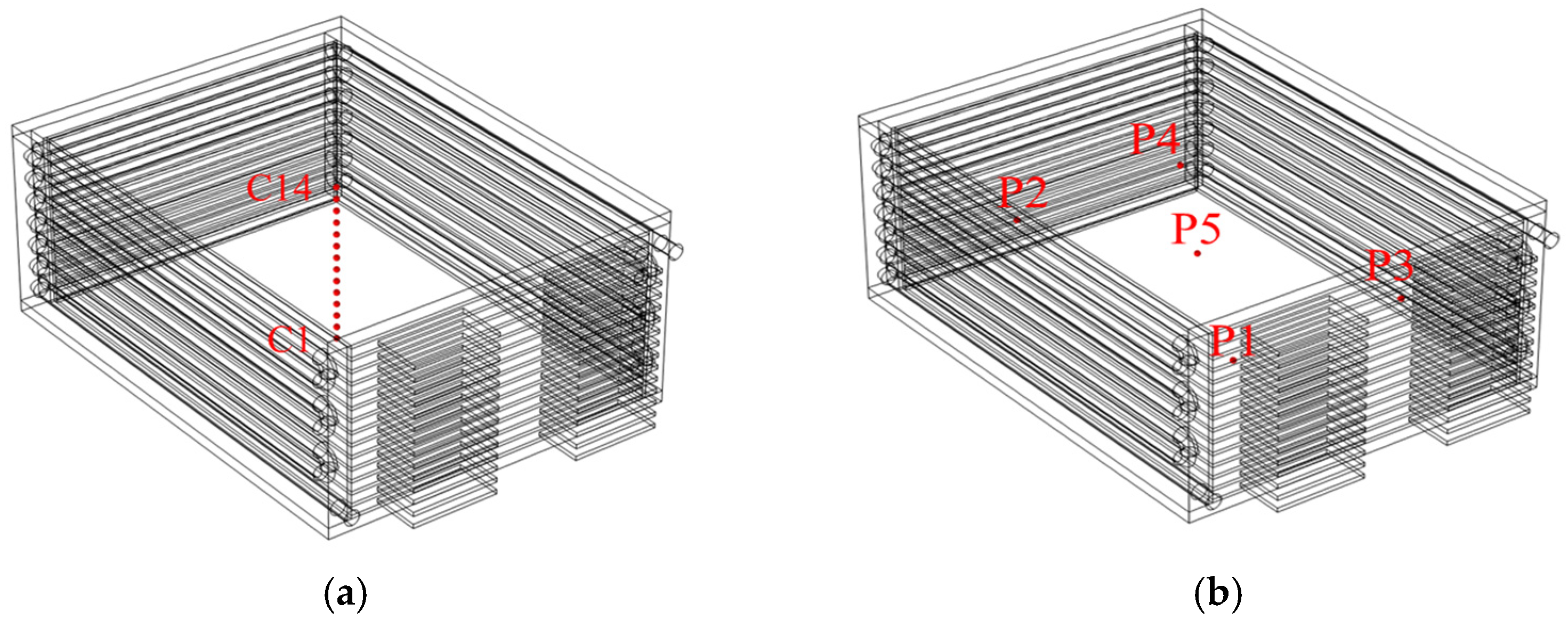
To assess the heat dissipation performance of the proposed scheme under extreme conditions, this study establishes a stringent ambient temperature of 45 °C. Simulation calculations are conducted across various practical application scenarios. These include a 90 s discharge at a maximum operating current of 320 A and a 7800 s pulse charge and discharge cycle at a commonly utilized working current of 80 A. Each battery within the battery module is designated as the specific subject of investigation. In
Figure 3a, the temperature variations at the centers of each of the 14 batteries, as well as at five points on the surface of the seventh battery (
Figure 3b), are presented. Through comprehensive data collection and analysis, this study examines the trends in surface temperature changes, the uniformity of the surface temperatures across each battery under varying conditions, and the thermal balance among the individual batteries. The objective is to evaluate the heat dissipation performance of the proposed scheme from multiple perspectives.
4.1. Heat Generation Analysis of Battery Pack Under Extreme Conditions
Prior to investigating the heat dissipation effects of the proposed cooling scheme, it is imperative to establish the temperature distribution of the battery pack in the absence of any heat dissipation mechanisms. Consequently, this study performs an analysis of the temperature rise due to heat generation during a single discharge of a battery pack that lacks a cooling structure, under an ambient temperature of 45 °C and a maximum discharge rate of 40 C. The pertinent temperature nephograms of the battery pack, cross-sectional nephograms, and the variations in the maximum temperature, minimum temperature, and temperature differential throughout the discharge duration are depicted in
Figure 4 and
Figure 5.
As seen in
Figure 4a, the temperature of the entire battery pack exhibits a significant increase. At the conclusion of the discharge process, the maximum temperature recorded for the cell body is 61.75 °C, while the minimum temperature is 59.47 °C, resulting in a temperature differential of 2.28 °C. The cross-sectional nephogram in
Figure 4b indicates that the temperature distribution within the battery pack is relatively uniform. This uniformity can be attributed to the absence of a cooling structure, which leads to comparable heat dissipation conditions across each cell within the pack. Therefore, heat accumulates uniformly, yielding a relatively consistent overall temperature distribution.
Subsequently, it is essential to elucidate the temperature equilibrium among the various cells within the battery pack. For each high-power cell, the requirement for temperature balance stipulates that the temperature differential must not exceed 5 °C. In the examination of the temperature balance within the battery pack, the average temperature or the central temperature of each battery is typically employed to monitor the temperature variation during discharge. In this study, based on the thermal characteristics of the power-type pouch cell, the center of each cell is designated as the measurement point. According to the monitoring data, the temperature at the center of the seventh cell is the highest, recorded at 61.75 °C, while the temperature of the first cell is the lowest, at 61.33 °C. The temperature difference between these two cells is a mere 0.42 °C. These data strongly suggest that there is a favorable temperature balance among the cells in the pack. This effective balance is attributed to the uniformity in the structure and materials of each cell, as well as the consistent distribution of the current during discharge, which results in similar heat generation conditions across the cells, thereby ensuring temperature equilibrium.
After assessing the temperature distribution and thermal equilibrium of the battery pack, it is found that the uniformity of the temperature across the surface of each cell significantly impacts the efficient operation of the battery. Therefore, it is essential to evaluate the surface temperature uniformity of a cell. Typically, the criterion stipulates that the temperature differential across the surface of each cell should not exceed 2 °C. To analyze the temperature uniformity of the surface of the seventh cell, five measurement points were selected. At the conclusion of the discharge cycle, the recorded temperatures at measurement points P1, P2, P3, P4, and P5 were 61.24 °C, 61.47 °C, 61.23 °C, 61.47 °C, and 61.51 °C, respectively. The maximum temperature difference observed between these points was a mere 0.28 °C. These data indicate that the temperature distribution across the surface of the battery is uniform. This uniformity can be attributed to the intrinsic material properties of the battery and the consistency of the internal chemical reactions during discharge, which facilitate the even conduction and distribution of heat across the surface.
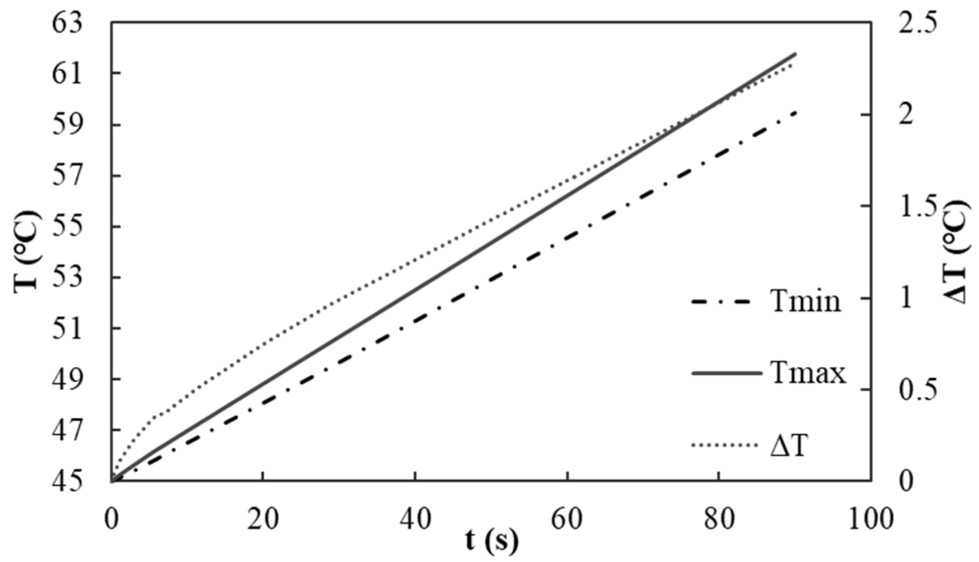
The variation characteristics of the maximum temperature, minimum temperature, and temperature differential at each moment are presented. As shown in
Figure 5, the temperature increase in the battery pack at the conclusion of the discharge process is 16.75 °C, with a temperature rise rate of 11.16 °C/min. Furthermore, the data pertaining to the maximum temperature, temperature differential, and temperature rise rate at specific intervals, namely 15 s, 30 s, 60 s, and 90 s, are outlined in
Table 3. Analyzing these data facilitates a more comprehensive understanding of the temperature change trends of the battery pack during the discharge phase. In the initial stage of discharge, rapid internal chemical reactions generate significant heat, resulting in a swift increase in temperature accompanied by a high rate of temperature rise. As the discharge progresses, the reactants within the battery are gradually depleted, leading to a decrease in the rate of heat generation and, consequently, a reduction in the temperature rise rate. Ultimately, a stable temperature rise state is achieved by the end of the discharge process.
4.2. Optimization of Thermal Conductive Plate Thickness in Battery Module
The thermal characteristics of the selected battery necessitate that its operating temperature be strictly maintained below 60 °C. Exceeding this threshold requires the battery to operate under reduced power conditions. When the temperature reaches 65 °C, the battery is at a heightened risk of damage and thermal runaway. Therefore, operations must be suspended immediately.
Previous simulation tests examining the temperature rise due to discharge heat generation in battery packs lacking a cooling structure have demonstrated that the temperature of the battery pack can exceed 60 °C, with the highest temperature concentrations occurring at the center of the pack. This observation indicates that heat dissipation in the central region of the battery is particularly challenging, underscoring the urgent need to enhance the heat dissipation mechanisms to remove the heat generated by the battery pack. To address this issue, a strategy has been implemented whereby each battery actively participates in the heat dissipation process. Specifically, an aluminum thermal conductive plate is inserted between each battery, thereby facilitating the outward conduction of heat generated by the batteries through the plate. The thickness of the thermal conductive plate is a critical factor affecting the heat dissipation efficiency of the battery module. A plate that is too thin may impede heat conduction, while one that is excessively thick can lead to material waste and an increase in the overall volume of the battery module. Therefore, determining the optimal thickness of the thermal conductive plate is essential to ensure efficient heat dissipation from the batteries while minimizing the volume of the module.
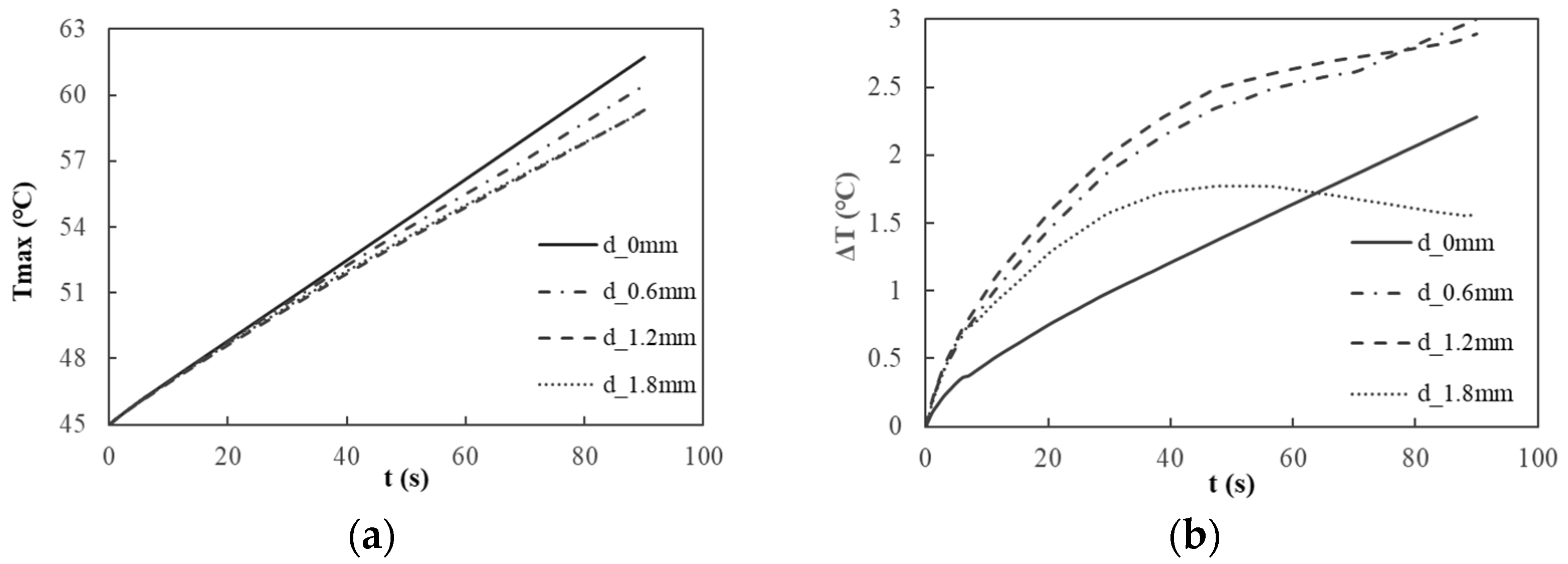
In this study, a comprehensive investigation was conducted on three thermal conductive plates with varying thicknesses (d) of 0.6 mm, 1.2 mm, and 1.8 mm, respectively. By analyzing the heat conduction effects of these plates within the battery module, the plate exhibiting optimal thickness was determined. The temperature rise and temperature differential of the battery module corresponding to the different thicknesses of the thermal conductive plates are illustrated in
Figure 6.
In relation to the suppression of the maximum temperature (
Figure 6a), the discharge temperature rise curve for the battery module indicates that, at the conclusion of the discharge process, the maximum temperatures recorded for the battery module are 60.43 °C for the 0.6-mm-thick plate, 59.33 °C for the 1.2-mm-thick plate, and 59.26 °C for the 1.8-mm-thick plate. The thermal conduction efficiency of the 0.6-mm-thick plate is significantly inferior to that of the other two plates. When the plate thickness exceeds 1.2 mm, the differences in the thermal conduction performance between the two thicker plates become negligible, with both exhibiting maximum temperatures below the battery’s maximum allowable operating temperature of 60 °C. In
Figure 6b, the characteristic curve of the discharge temperature difference for the battery module reveals that the maximum temperature difference for the battery utilizing the 1.8-mm-thick plate is the smallest, measuring only 1.77 °C.
Based on the results mentioned above, the 0.6-mm-thick heat-conducting plate was initially excluded from consideration. Subsequently, a more comprehensive comparative analysis was conducted to evaluate the temperature equilibrium of the battery cells and the surface temperature uniformity of the two modules utilizing 1.2- and 1.8-mm-thick heat-conducting plates. In the case of the 1.2-mm-thick plate, the maximum central point temperature recorded for the battery cells was 59.33 °C at the eighth cell. In contrast, the minimum temperature was 58.10 °C at the first cell, resulting in a temperature differential of 1.23 °C. Conversely, for the 1.8-mm-thick plate, the highest central point temperature was 59.14 °C at the first cell, and the lowest was 58.36 °C at the 10th cell, yielding a temperature difference of only 0.78 °C. To assess the uniformity of the surface temperature, five points on the surface of the seventh cell were analyzed. For the plate with a thickness of 1.2 mm, the recorded temperatures at points P1 through P5 were 58.76 °C, 58.83 °C, 58.74 °C, 58.83 °C, and 58.84 °C, resulting in a temperature differential of 0.09 °C. In contrast, for the plate with a thickness of 1.8 mm, the temperatures at points P1 through P5 were measured at 57.79 °C, 57.80 °C, 57.80 °C, 57.80 °C, and 57.80 °C, yielding a minimal temperature difference of 0.01 °C.
In light of the temperature distribution, maximum temperature, temperature differentials, thermal equilibrium and uniformity of individual cells, and structural considerations, the optimal thickness of the heat-conducting plate for the battery module has been established at 1.8 mm. This specified thickness facilitates efficient heat dissipation, effectively mitigates temperature disparities among the cells, enhances the temperature uniformity, and maintains the structural integrity, thereby fulfilling the practical requirements for the performance and spatial configuration of the battery module.
4.3. Verification of Liquid Cooling Scheme
This study focuses on the battery’s temperature variation during a 90 s discharge process to assess the heat dissipation efficacy of the design scheme presented. The experimental conditions include an ambient temperature of 45 °C and an extreme discharge rate of 40 C. In the simulation, water is selected as the cooling medium, with the cooling liquid temperature maintained at 45 °C and a flow rate of 12 g/s.
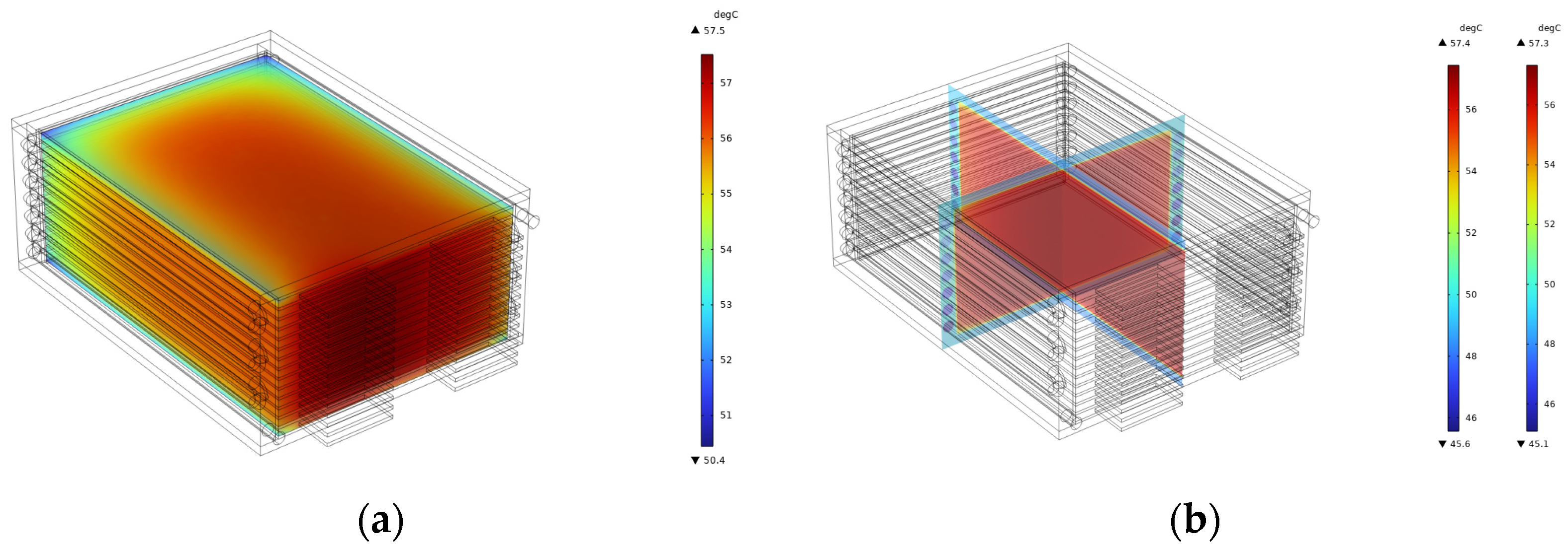
The temperature nephogram of the liquid-cooled battery module is presented in
Figure 7a, while the cross-sectional nephogram is illustrated in
Figure 7b. An analysis of these charts reveals that, at the conclusion of the discharge cycle, the maximum temperature of the battery body reaches 57.51 °C, which is below the threshold of 60 °C, thereby satisfying the operational temperature requirements for the battery. The minimum temperature recorded is 50.08 °C, resulting in a temperature difference of 7.43 °C. An examination of the cross-sectional nephogram indicates that batteries positioned closer to the inner wall of the shell’s U-shaped cavity exhibit lower temperatures. In contrast, those nearer to the center of the module demonstrate higher temperatures. In this heat dissipation configuration, the cooling liquid initially exchanges heat with the batteries adjacent to the inner wall of the U-shaped cavity, effectively removing a certain proportion of heat and consequently reducing their temperatures. As heat is conducted towards the center of the module, a gradual increase in temperature is observed. Furthermore, the simulation assumes direct contact between the battery side surface and the shell wall. In practice, however, a layer of silica gel or foam, approximately 1~2 mm thick, is interposed between the battery and the shell, and the pouch battery is encased in an aluminum–plastic film with seals. These factors contribute to thermal resistance, which mitigates the temperature difference within the battery module body.
Figure 8 depicts the variation characteristics of the maximum and minimum temperatures at various time intervals. At the conclusion of the discharge process, the module temperature increases by 12.51 °C, corresponding to a temperature rise rate of 8.34 °C/min. In comparison to a battery pack lacking a cooling structure, this temperature increase is mitigated by 4.24 °C. These results indicate that the liquid cooling system can substantially diminish the temperature rise of the battery module during discharge, thereby enhancing the heat dissipation efficiency.
Table 4 provides a detailed account of the maximum temperature, temperature differential, and temperature rise rate at specific time points, including 15 s, 30 s, 60 s, and 90 s.
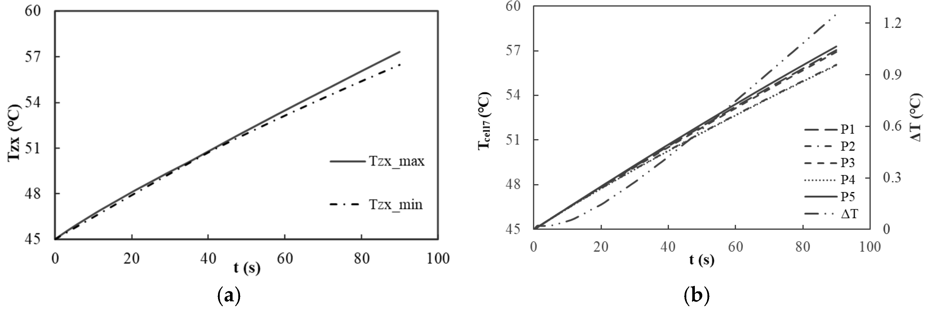
Figure 9a illustrates the variations in the maximum and minimum temperatures at the center of each battery in relation to the discharge duration. At the conclusion of the discharge cycle, the maximum temperature recorded at the center of each battery is 57.29 °C, while the minimum temperature is 56.43 °C, resulting in a temperature differential of only 0.86 °C. Although this value exceeds the 0.44 °C observed in a non-cooled battery pack, the overall temperature uniformity among the batteries is commendable, satisfying the temperature balance requirements necessary for the efficient operation of the battery module. This uniformity can be attributed to the effective heat conduction and dissipation properties of the liquid cooling structure, which enables each battery to maintain a relatively consistent temperature change trend during both heat generation and dissipation.
Following the assessment of the temperature distribution and balance within the liquid-cooled battery module, an investigation into the uniformity of the temperature distribution across the battery surface was conducted.
Figure 9b depicts the variations in temperature and the temperature differences at five measurement points on the surface of the seventh battery. At the conclusion of the discharge cycle, the recorded temperatures at measurement points P1, P2, P3, P4, and P5 were 57.05 °C, 56.06 °C, 56.90 °C, 56.02 °C, and 57.28 °C, respectively, resulting in a maximum temperature difference of 1.25 °C. In contrast, the maximum temperature difference observed in a non-cooled battery pack was 0.275 °C, indicating an increase in surface temperature variation. However, the overall surface temperature remains relatively uniform, thereby satisfying the requirements for temperature distribution uniformity across the battery surface. This result suggests that the liquid cooling system not only effectively manages the overall temperature of the battery pack but also ensures consistent temperature distribution across the battery surface, thereby mitigating the adverse impacts on battery performance that may arise from excessive temperature discrepancies.
The simulation verification of the liquid cooling system under extreme discharge rate conditions effectively demonstrates its capability to regulate the temperature of the battery module. However, due to the inherent limitations of single-discharge simulations, this approach cannot adequately verify or ensure compliance with the requirements for long-term operation, as well as the frequent charging and discharging encountered in practical applications. Therefore, this study further investigates the temperature variation during a 7800 s charging and discharging process under a 10 C common rate pulse cycle condition, with an ambient temperature of 45 °C. Water is utilized as the cooling medium, and the simulation is conducted with the cooling liquid temperature maintained at 45 °C and a flow rate of 12 g/s.
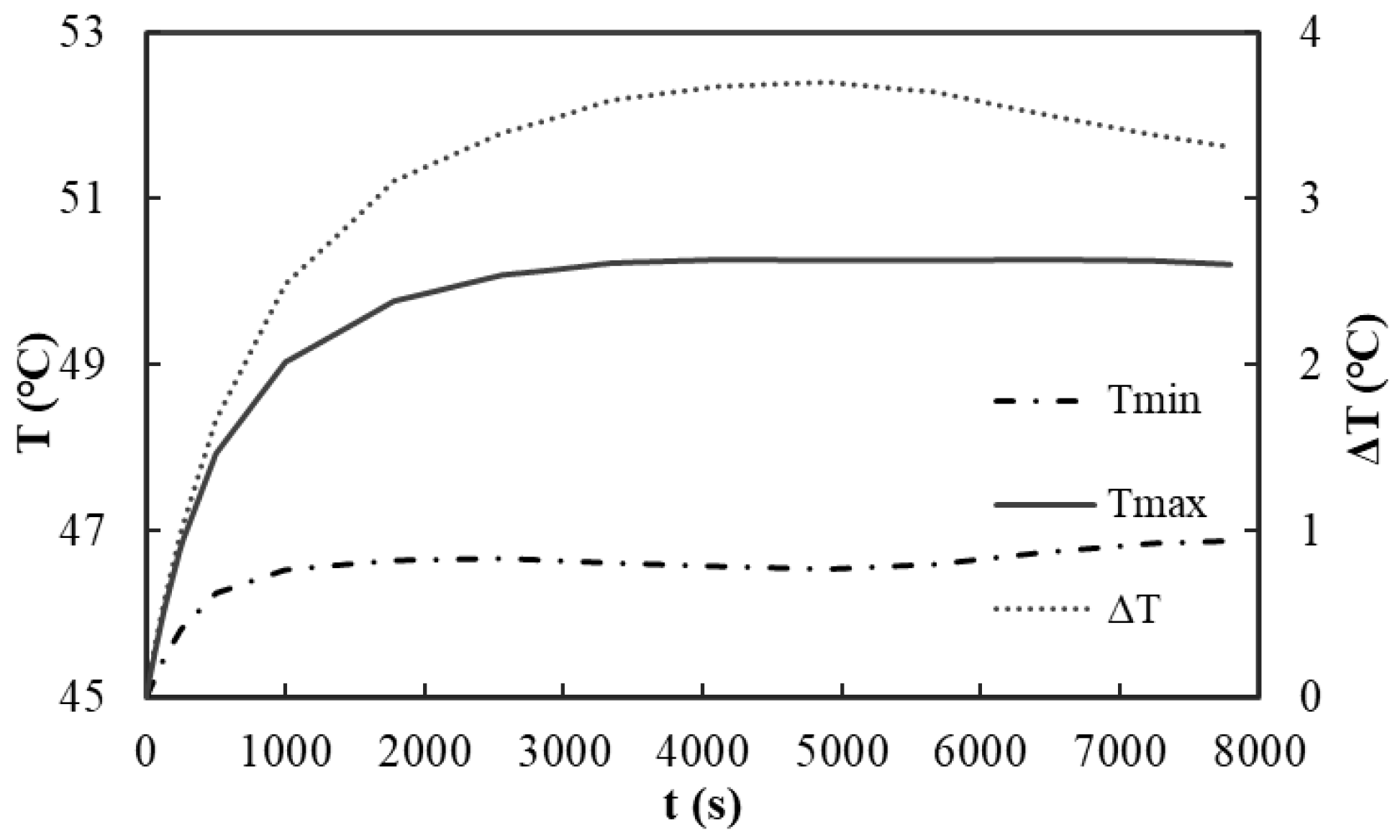
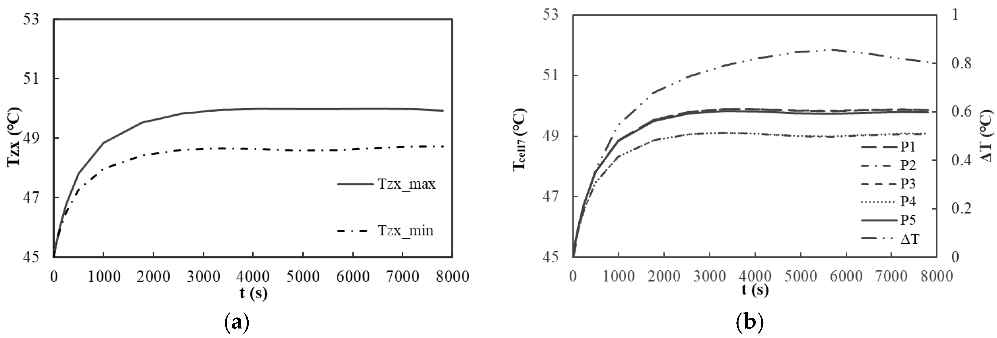
Figure 10 illustrates the variation characteristics of the maximum temperature, minimum temperature, and temperature differential of the liquid-cooled battery module during pulse cycle operation over time. The temperature of the battery body initially increases gradually at a moderate rate. At 4900 s, the total increase in the battery body temperature is 5.24 °C, after which it transitions into a relatively stable state. The maximum temperature of the battery body reaches 50.24 °C, while the minimum temperature remains at 46.55 °C, resulting in a temperature differential of 3.69 °C. These results indicate that the liquid cooling system effectively regulates the amplitude of the temperature rise in the battery body during prolonged operation, thereby maintaining a relatively stable thermal state and preventing potential damage to battery performance due to excessive temperatures.
Figure 11a depicts the variations in the maximum and minimum temperatures at the center of each battery throughout the operating time. The temperature at the center of each battery exhibits a gradual increasing trend. At 4900 s, the maximum temperature reaches 50.00 °C, subsequently stabilizing. The minimum temperature recorded at the center of each battery is 48.59 °C, resulting in a temperature differential of only 1.41 °C. This minimal difference indicates a commendable temperature balance among the batteries within the module under the specified conditions. These results further reveal that the liquid cooling structure effectively maintains temperature consistency among the batteries, even under complex operational conditions, thereby preventing performance imbalances within the battery module that could arise from excessive temperature disparities among individual batteries.
Figure 11b illustrates the variations in the temperature and temperature difference across five measuring points on the surface of the seventh battery under pulse cycle conditions as a function of the operating time. At 4900 s, the recorded temperatures are as follows: point P1 at 49.84 °C, point P2 at 49.00 °C, point P3 at 49.85 °C, point P4 at 49.00 °C, and point P5 at 49.76 °C. These result in a maximum temperature difference of only 0.85 °C. This indicates that the temperature distribution on the surfaces of the batteries within the module is relatively uniform under these conditions, thereby further validating the efficacy of the liquid cooling system in maintaining temperature consistency across the surface of each battery.
This paper has thus far validated the heat dissipation efficacy of the liquid-cooled module under extreme ambient conditions of 45 °C, specifically during a 40 C extreme discharge and a 10 C pulse cycle of charging and discharging. The results indicate that the module satisfactorily meets the requisite performance standards. Although, theoretically, there is no need to assess the heat dissipation effect at alternative ambient temperatures, a comprehensive and multidimensional approach is adopted to enhance the rigor and applicability of this research. An analysis of single-factor effects is conducted by varying parameters such as the ambient temperature (30 °C, 40 °C, 45 °C), cooling liquid flow rate (8 g/s, 12 g/s, 16 g/s), and inlet temperature (30 °C, 40 °C, 45 °C) to analyze the heat dissipation performance of the liquid-cooled module under diverse conditions. The results (
Table 5 and
Table 6) confirm that the design is sound and capable of fulfilling practical application requirements across various scenarios. This strongly supports the assertion that the U-shaped “bathtub-type” cooling structure proposed in this study, along with the associated parameter settings, possesses broad applicability and reliability, thereby offering a viable solution for the thermal management of high-power-density battery modules.
5. Thermal Performance Test of Liquid-Cooled Battery Module
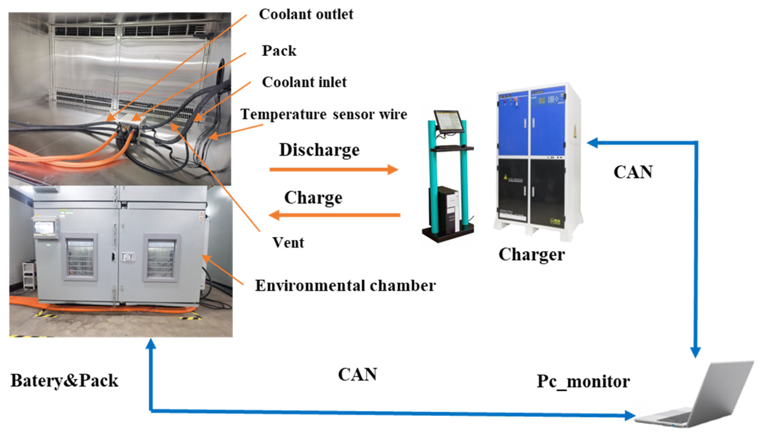
The objective of the battery module temperature rise test is to assess the engineering effectiveness of the heat dissipation structure design and to verify the accuracy of the model. The battery module is situated within a constant-temperature and -humidity chamber to ensure a stable testing environment, with the test conditions mirroring those of the simulation to facilitate precise comparisons. The test bench (
Figure 12) comprises a battery module, a charge–discharge device, an environmental chamber, a monitoring personal computer, cables, and a cooling system. The charge–discharge device is equipped with programmable functions, while the monitoring personal computer is capable of real-time data monitoring and test program control, thereby recording the battery parameters.
Typically, heat dissipation tests for battery modules require assessments at multiple ambient temperatures. However, due to the extensive volume of tests, this study, which references simulations, is limited to conducting a 40 C extreme rate discharge and a 10 C common rate pulse cycle charge and discharge test at 45 °C. During these tests, various temperatures are monitored, including the ambient temperature, the maximum temperature of the module, the center temperature of each battery, and five points on the surface of the seventh battery during operation. Testing at 45 °C simulates conditions of high-temperature operation, thereby validating the performance of the heat dissipation structure under extreme conditions. The two testing conditions are designed to evaluate the thermal performance of the module across different operational modes.
The discharge testing procedures are as follows. Here, a discharge rate of 40 C is used as an illustration.
First, we place the module in an environmental chamber maintained at 45 °C for 2 hours. Then, we charge it at a rate of 0.5 C until the terminal voltage reaches 50.4 V. Subsequently, we conduct a constant-voltage charging process at 50.4 V and stop charging when the current drops to 0.01 C.
After a 30-min rest period, we continuously discharge the battery pack at a rate of 40 C. We terminate the discharging process either when the discharge duration reaches 90 s or when the battery voltage drops below 30.8 V.
During the discharging process, the data acquisition unit records the temperature data.
At 45 °C with the 40 C scenario (
Table 7), the maximum temperature at the center of each battery (T
zxmax) reaches 56.1 °C, which is below the threshold of 60 °C. The difference between the simulation results and the test results is 1.28 °C, and the relative error is 2%. This result validates the effective heat dissipation capabilities under extreme discharge rates. Furthermore, the maximum temperature difference at the center of each battery (ΔT
zx) is recorded as 1.2 °C, suggesting a favorable temperature balance among the batteries. The temperature differential (ΔT
cell7) across five points on the surface of the seventh battery is measured at 1.2 °C, indicating commendable uniformity in the surface temperature. During the 10 C common operating rate pulse cycle test, the temperature of the module exhibits a gradual increase. At 4900 s, the T
zxmax recorded is 50.7 °C. The temperature differentials ΔT
zx and ΔT
cell7 are 1.5 °C and 0.6 °C, respectively, which align with the design expectations and confirm the stability of the module’s thermal performance under conditions of frequent charging and discharging.
The test results align closely with the simulations, thereby demonstrating the effectiveness of the heat dissipation structure design and the accuracy of the model. This alignment provides a solid experimental foundation for practical applications.
6. Conclusions
This study addresses the thermal management of high-power-density battery modules, validating the effectiveness of the proposed cooling design through theoretical analysis, simulations, and experimental validation. The key conclusions are summarized as follows.
Under the extreme condition of a 45 °C ambient temperature and a 40 C discharge rate for 90 s, simulations demonstrate that the liquid-cooled battery module maintains a peak temperature of 57.51 °C, which is well below the operational threshold of 60 °C. Furthermore, the temperature uniformity among the cells is excellent, with the temperature difference between the maximum (57.29 °C) and minimum (56.43 °C) cell centers being only 0.86 °C. The surface temperature of the seventh cell, monitored at five points, exhibits a maximum variation of 1.25 °C.
For a 10 C charge/discharge pulse cycle at 45 °C over 7800 s, simulations indicate that the liquid cooling system efficiently manages temperature rises. At 4900 s, the battery temperature stabilizes with a temperature increase of 5.24 °C, reaching a maximum of 50.24 °C and a minimum of 46.55 °C, with a temperature difference of 3.69 °C. The temperature difference among the center points of individual cells is 1.41 °C (maximum 50.0 °C, minimum 48.59 °C), and the surface temperature variation of the seventh cell is contained within 0.85 °C.
Single-factor sensitivity analyses, varying the ambient temperature, coolant flow, and inlet temperature, demonstrate the rational design of the U-shaped “bathtub-type” cooling structure. This design meets practical requirements across diverse operating conditions, providing a reliable and broadly applicable solution for high-power-density battery module thermal management.
This study’s cooling structure offers clear advantages. It efficiently controls the battery module temperature under various discharges. The design, with an integrated aluminum heat plate and serpentine channel, dissipates heat well, ensuring a good temperature balance and uniformity. This stabilizes battery operations and extends its life. Sensitivity analyses show wide applicability, making it a reliable thermal management solution for high-power-density modules. Adding intelligent controls in the future could optimize it further, improving the performance and meeting evolving needs to advance battery technology.


