
An Improved PSO-Based DC Discharge Heating Strategy for Lithium-Ion Batteries at Low Temperatures

Abstract
1. Introduction
2. Materials and Methods
2.1. Battery Model Development
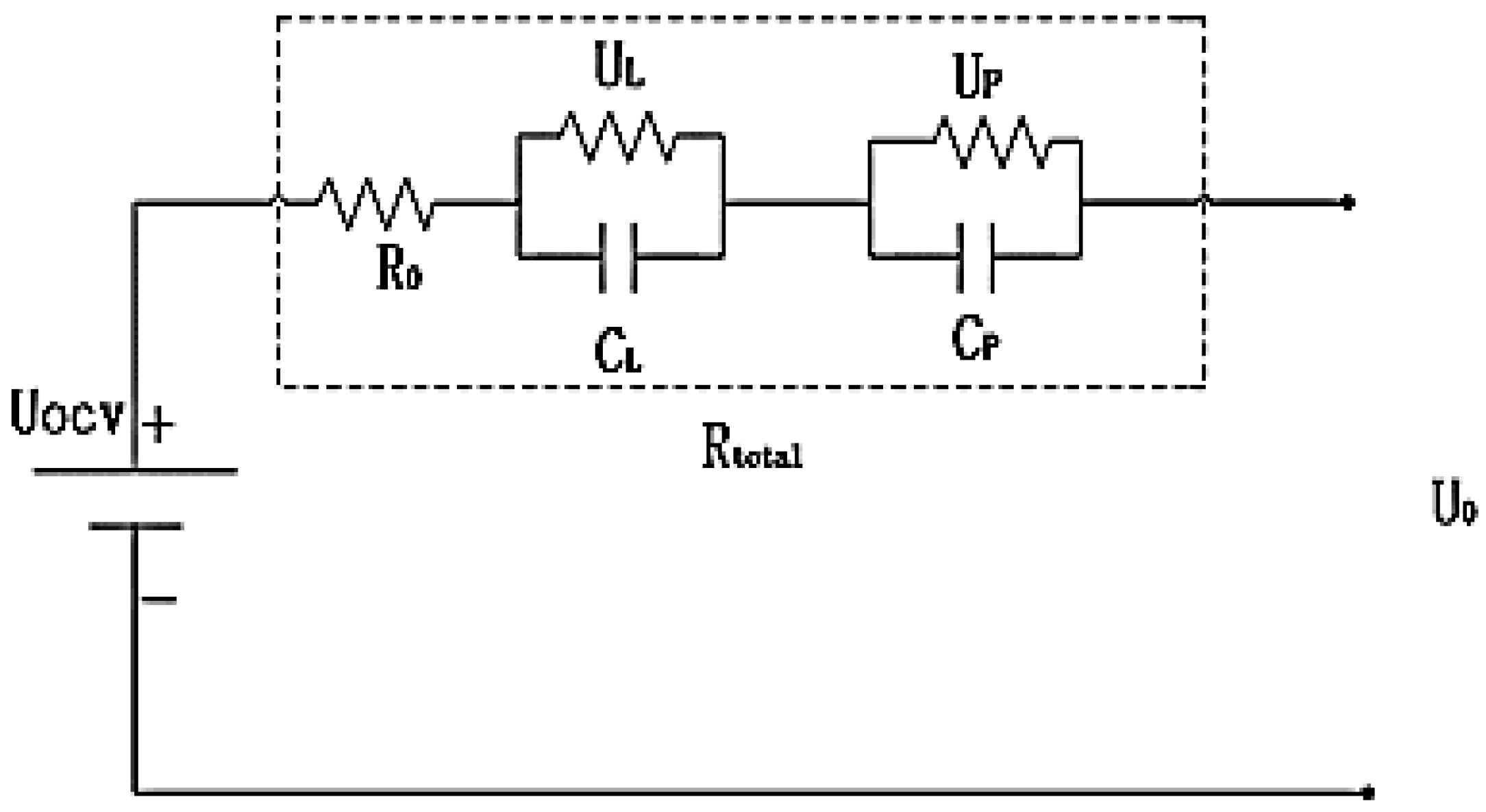
2.1.1. Development of the Battery Equivalent Circuit Model
2.1.2. Development of the Battery Heat Generation Model
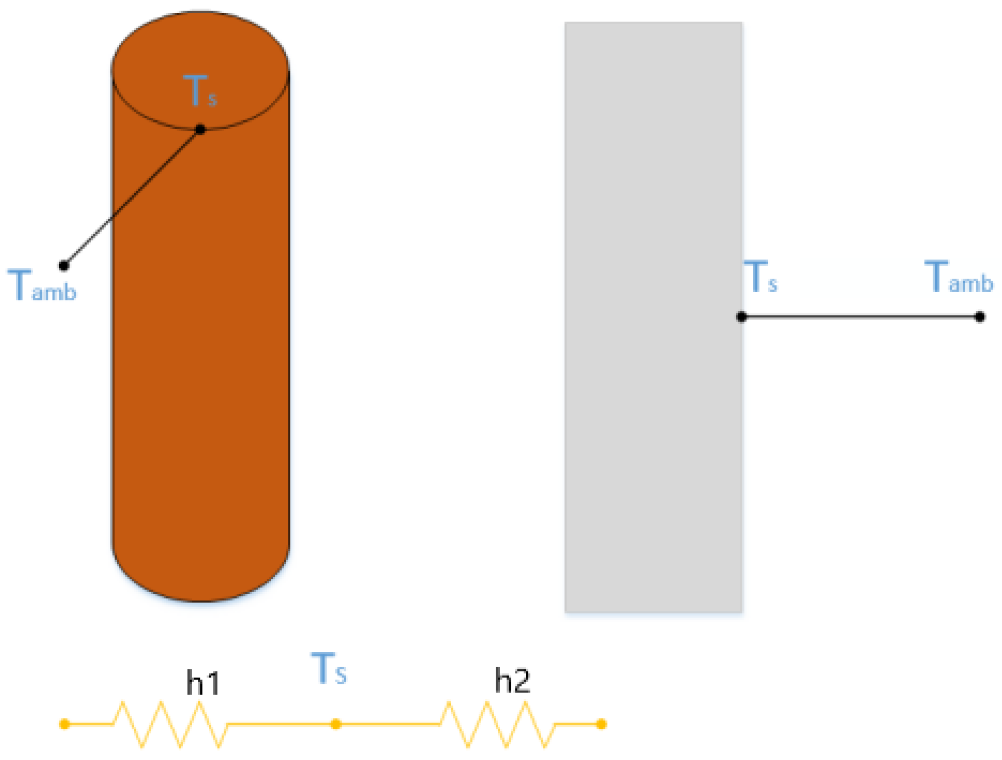
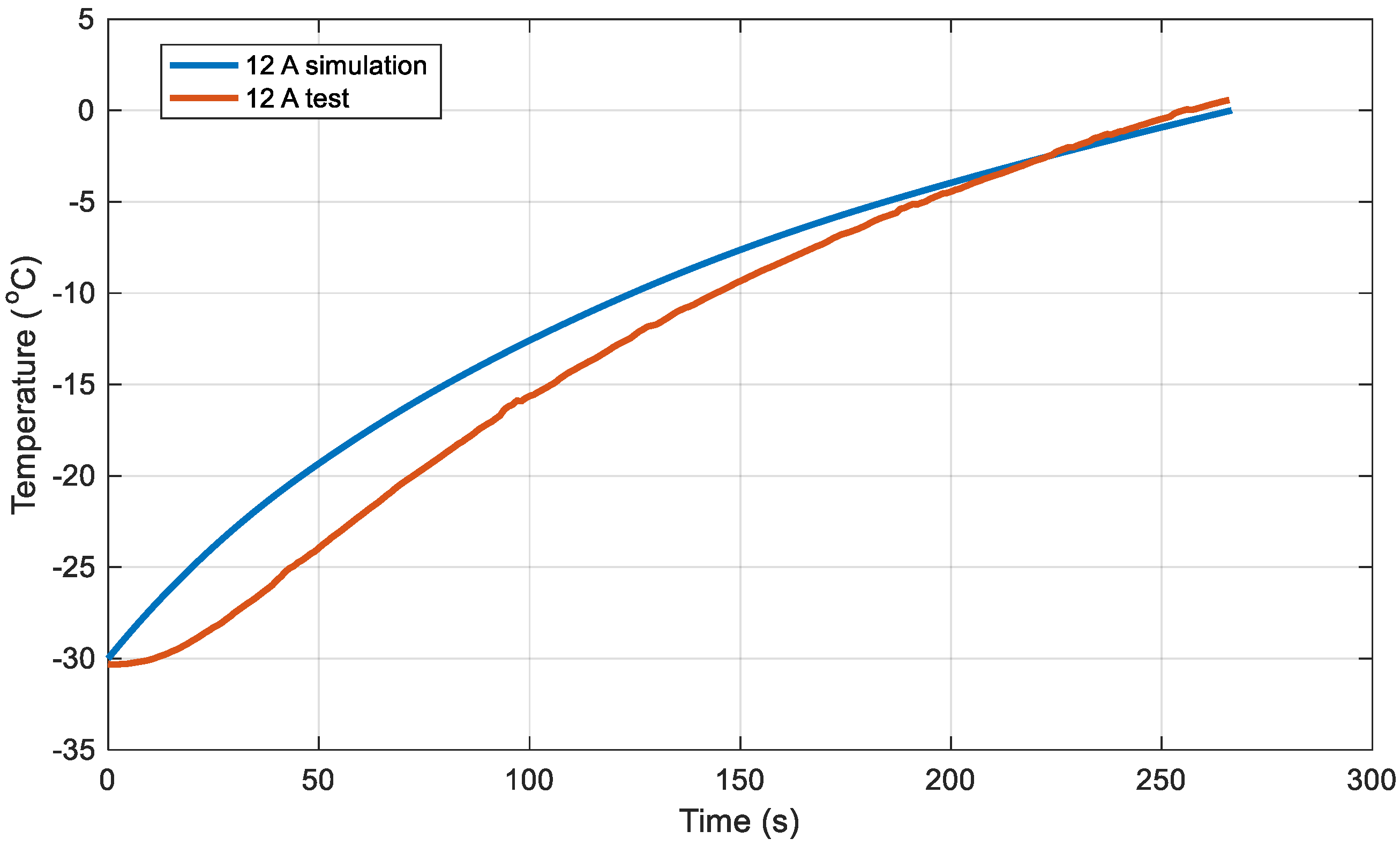
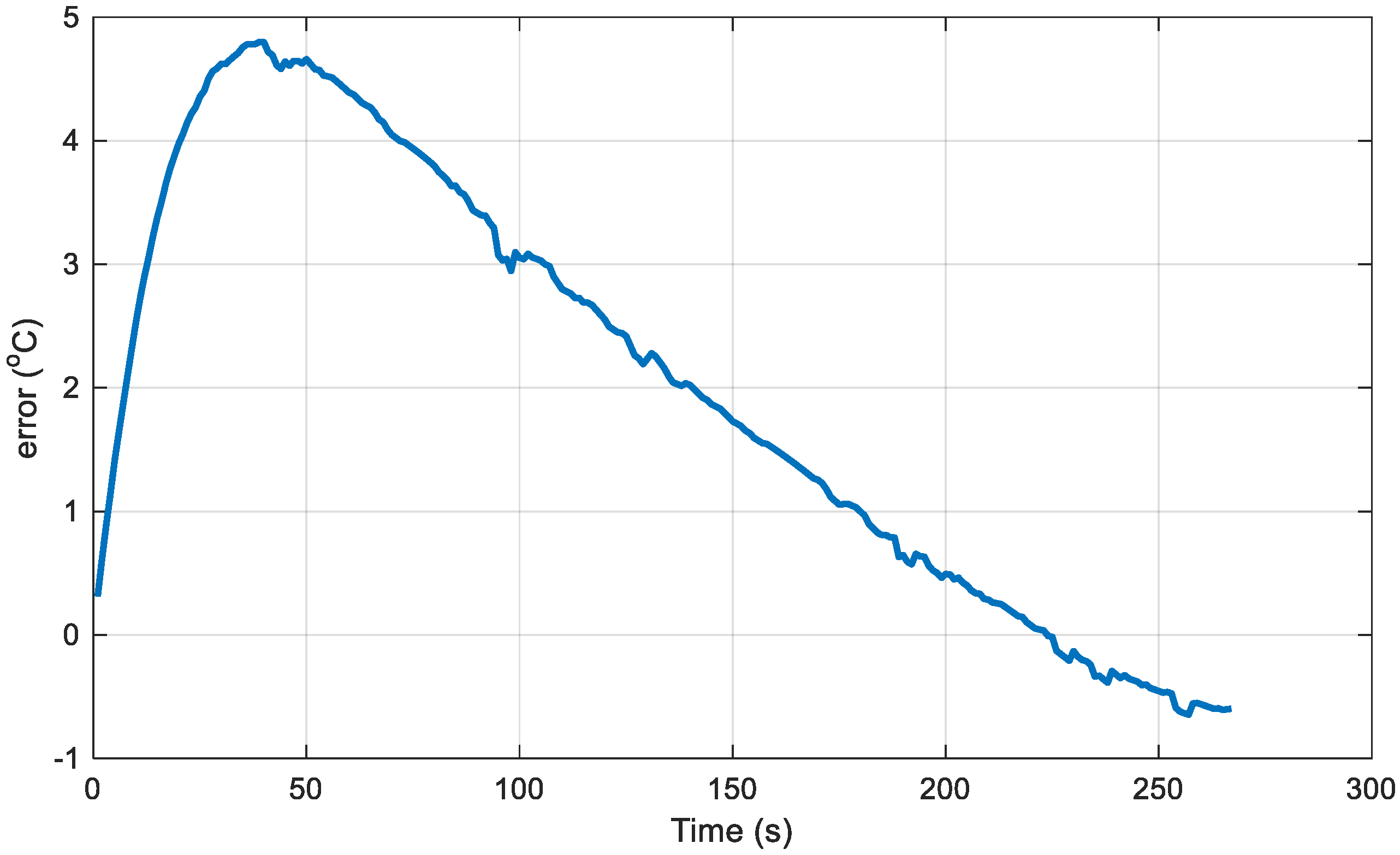
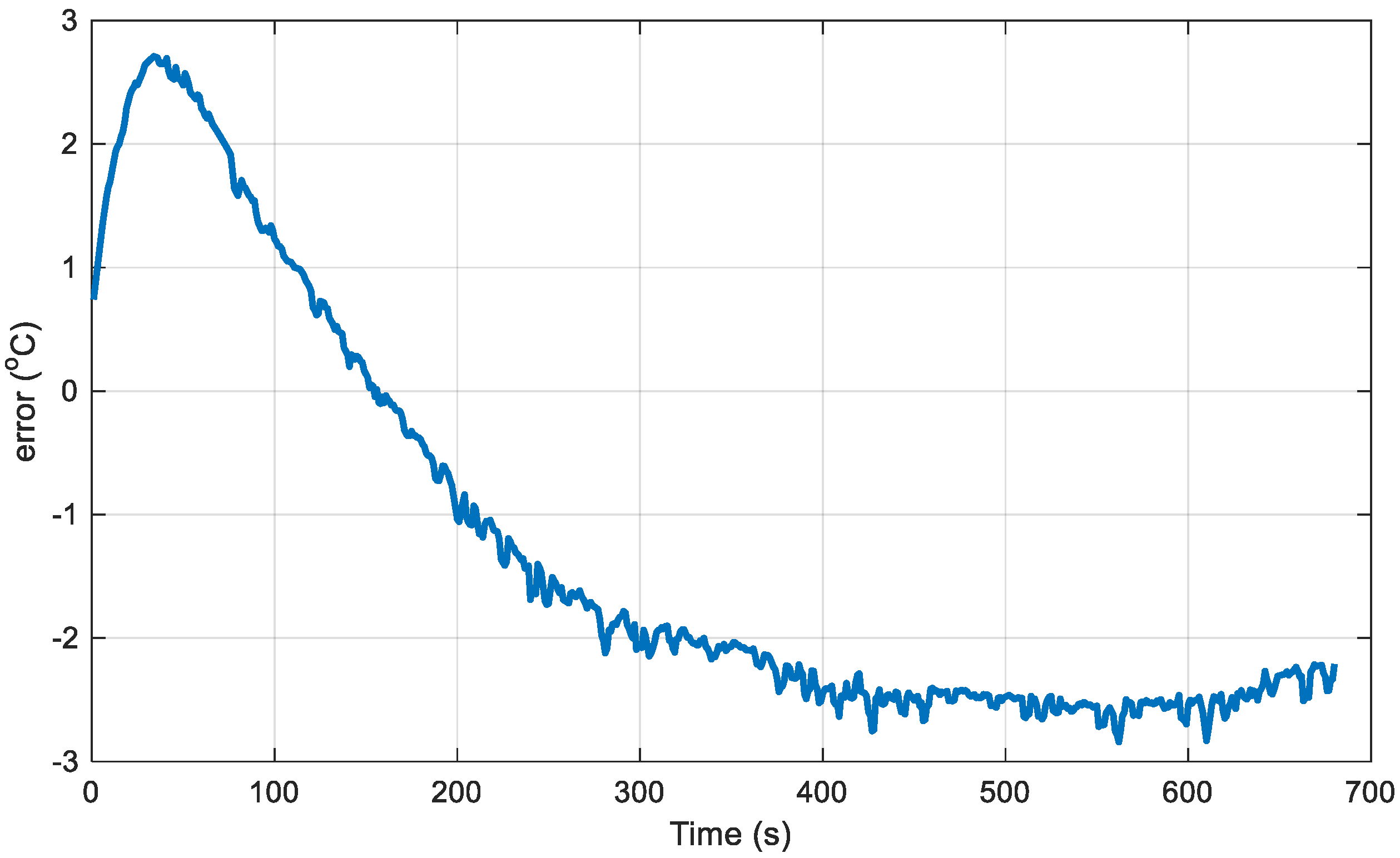
2.1.3. Development of a Thermoelectric Coupling Temperature Rise Simulation Model
2.2. Low-Temperature Preheating Optimization Strategy for Batteries Based on the PSO Optimization Algorithm
2.2.1. Determining the Optimization Objective Function for Battery Low-Temperature Preheating
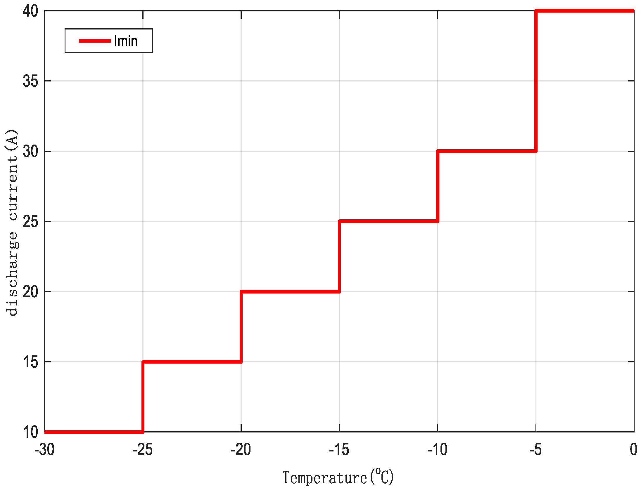
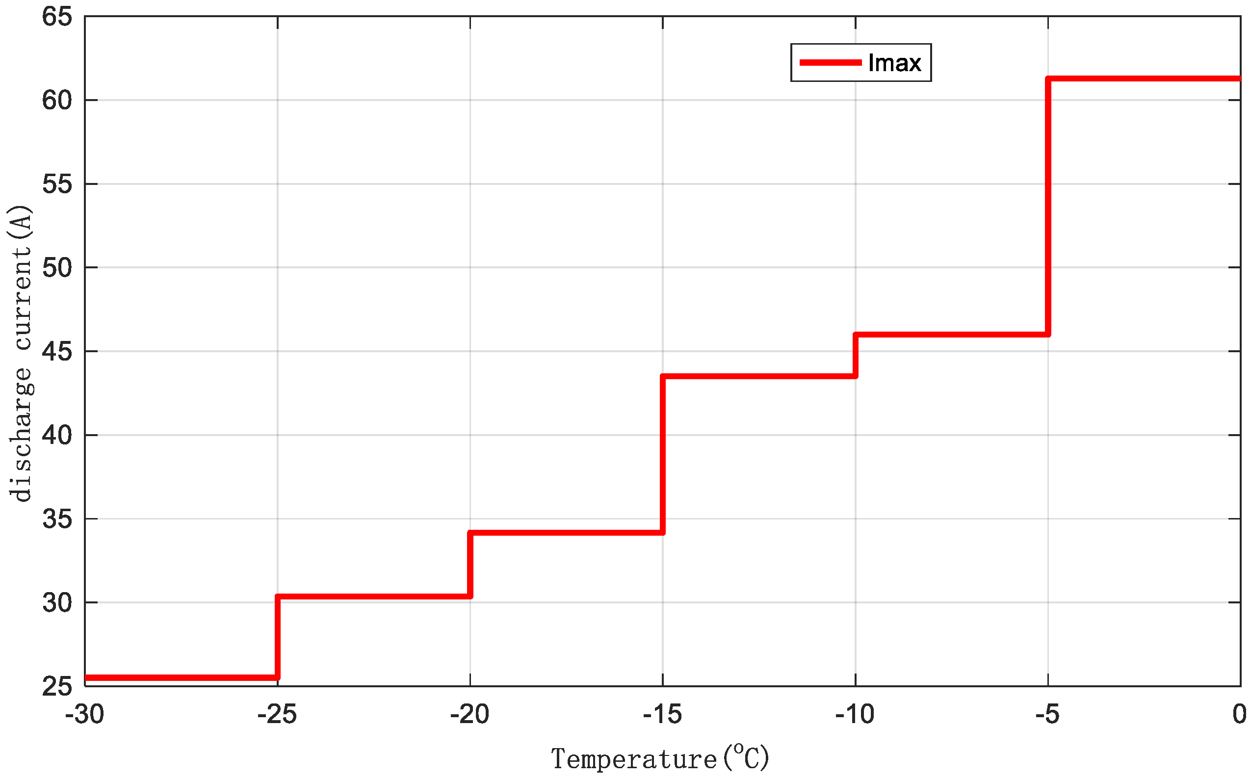
2.2.2. Setting Boundary Conditions for Discharge Current
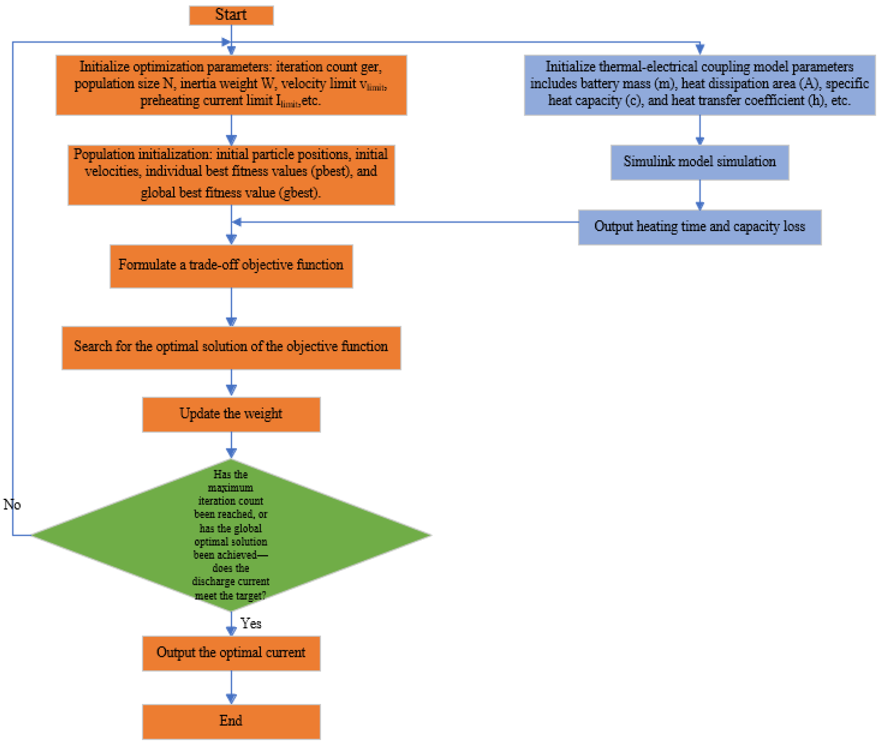
2.2.3. Discharge Current Solution Based on the PSO Optimization Algorithm
3. Results
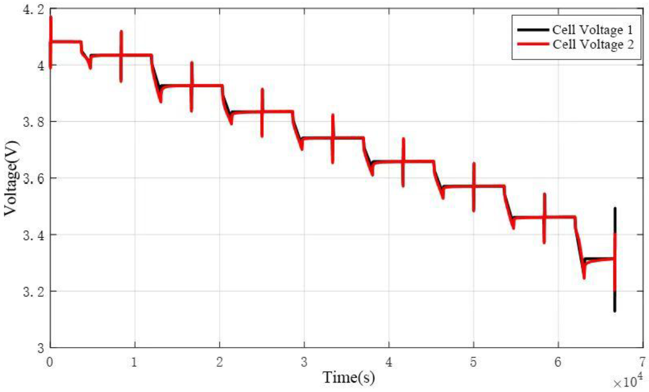
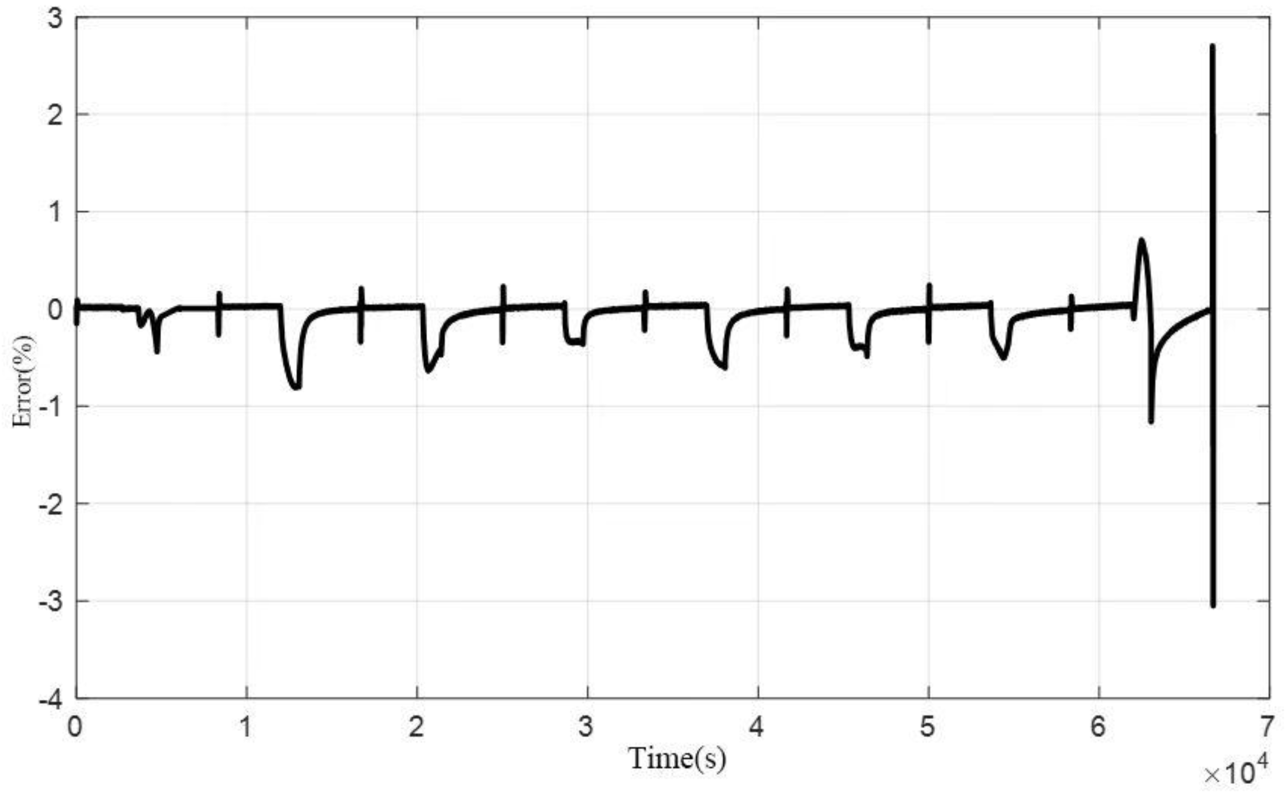
3.1. Research Results of Discharge Heating Optimization Method
3.2. Results of the Constant-Current Discharge Method
3.3. Power Consumption Comparative Analysis
4. Discussion
Author Contributions
Funding
Data Availability Statement
Conflicts of Interest
Abbreviations
| EVs | electric vehicles |
| DC | direct current |
| PSO | Particle Swarm Optimization |
| AC | alternating current |
| CSH | composite self-heating |
| SOC | state of charge |
| DP | Dual Polarization |
| OCV | open-circuit voltage |
| HPPC | Hybrid Pulse Power Characterization |
| BMS | battery management systems |
References
- Liu, D.; Zhou, J.; Guo, L.; Peng, Y. Survey on lithium-ion battery health assessment and cycle life estimation. Chin. J. Sci. Instrum. 2015, 36, 1–16. [Google Scholar]
- Park, H. A Design of Air Flow Configuration for Cooling Lithium ion Battery in Hybrid Electric Vehicles. J. Power Sources 2013, 239, 30–36. [Google Scholar] [CrossRef]
- Bandhauer, T.M.; Garimella, S.; Fuller, T.F. A Critical Review of Thermal Issues in Lithium-Ion Batteries. J. Electrochem. Soc. 2011, 158, R1. [Google Scholar] [CrossRef]
- Zhang, J.; Ge, H.; Li, Z.; Ding, Z. Internal Heating of Lithium-ion Batteries using Alternating Current based on the Heat Generation Model in Frequency Domain. J. Power Sources 2015, 273, 1030–1037. [Google Scholar] [CrossRef]
- Bae, S.; Song, H.D.; Nam, I.; Kim, G.-P.; Lee, J.M.; Yi, J. Quantitative Performance Analysis of Graphite-LiFePO4 Battery Working at Low Temperature. Chem. Eng. Sci. 2014, 118, 74–82. [Google Scholar] [CrossRef]
- Cho, H.-M.; Choi, W.-S.; Go, J.-Y.; Bae, S.-E.; Shin, H.-C. A Study on Time-Dependent Low Temperature Power Performance of a Lithium-ion Battery. J. Power Sources 2012, 198, 273–280. [Google Scholar] [CrossRef]
- Zhao, X.W.; Zhang, G.Y.; Yang, L.; Qiang, X.; Chen, Q. A new charging mode of Li-ion batteries with LiFePO4/C composites under low temperature. J. Therm. Anal. Calorim. 2011, 104, 561–567. [Google Scholar] [CrossRef]
- Tippmann, S.; Walper, D.; Balboa, L.; Spier, B.; Bessler, W.G. Low-temperature Charging of Lithium-ion Cells Part I: Electrochemical Modeling and Experimental Investigation of Degradation Behavior. J. Power Sources 2014, 252, 305–316. [Google Scholar] [CrossRef]
- Chang, W.; Kim, S.-J.; Park, I.-T.; Cho, B.-W.; Chung, K.Y.; Shin, H.-C. Low Temperature Performance of LiFePO4 Cathode Material for Li-ion Batteries. J. Alloys Compd. 2013, 563, 249–253. [Google Scholar] [CrossRef]
- Ji, Y.; Wang, C.Y. Heating Strategies for Li-ion Batteries Operated from Subzero Temperatures. Electrochim. Acta 2013, 107, 664–674. [Google Scholar] [CrossRef]
- Zeng, S.H.; Wu, W.X.; Liu, J.Z.; Wang, S.F.; Ye, S.F.; Feng, Z.Y. Review of immersion cooling technology for lithium-ion batteries. Energy Storage Sci. Technol. 2023, 12, 2888–2903. [Google Scholar]
- Zhu, J.W.; Huang, L.S.; Chen, X.J.; Zhang, X.Q. Capacitor-based self-heating method for low-temperature discharge of lithium batteries. Power Electron. Technol. 2023, 57, 77–79, 84. [Google Scholar]
- Pesaran, A.A. Energy efficient battery heating in cold climates. SAE Trans. 2002, 111, 377–382. [Google Scholar]
- Zhang, C.; Huang, J.; Sun, W.; Xu, X.; Li, C.; Li, Y. Research on liquid preheating performance for battery thermal management of electric vehicles at low temperature. J. Energy Storage 2022, 55, 105497. [Google Scholar] [CrossRef]
- Yu, T.; Liu, S.; Li, X.; Shi, W. Optimization of objective temperature for battery heating at low temperatures to improve driving range and battery lifetime of battery electric vehicles. Appl. Therm. Eng. 2025, 270, 126119. [Google Scholar] [CrossRef]
- Wang, C.; Tang, Q.; Sun, T.; Feng, X.; Shen, K.; Zheng, Y.; Ouyang, M. Application of high frequency square wave pulsed current on lithium-ion batteries at subzero temperature. J. Power Sources 2025, 633, 236413. [Google Scholar] [CrossRef]
- Lai, P.E.; Chang, S.C.; Chang, Y.S. Implementation of Heating System for Lithium-Ion Batteries in Low Temperature Environments. In Proceedings of the 2024 13th International Conference on Renewable Energy Research and Applications (ICRERA), Nagasaki, Japan, 9–13 November 2024; IEEE: Piscataway, NJ, USA, 2024; pp. 1363–1368. [Google Scholar]
- Cui, W.; Li, Y.; Ma, Z.-Y.; Nie, J.-X.; Liu, Y.-C. High-Frequency AC Heating Strategy of Electric Vehicle Power Battery Pack in Low-Temperature Environment. ACS Omega 2024, 9, 12753–12767. [Google Scholar] [CrossRef]
- Shang, Y.; Chen, G.; Peng, Q.; Zhu, T.; Liu, K. An intelligent preheating approach based on high-gain control for lithium-ion batteries in extremely cold environment. IEEE Trans. Ind. Electron. 2023, 71, 4697–4706. [Google Scholar] [CrossRef]
- Bao, J.; Zhou, Z.; Wu, W.-T.; Wei, L.; Lyu, J.; Li, Y.; Huang, H.; Li, Y.; Song, Y. Experimental study on liquid immersion preheating of lithium-ion batteries under low temperature environment. Case Stud. Therm. Eng. 2024, 60, 104759. [Google Scholar] [CrossRef]
- Cao, W.; Xu, X.; Wei, Z.; Wang, W.; Li, J.; He, H. Synergized heating and optimal charging of lithium-ion batteries at low temperature. IEEE Trans. Transp. Electrif. 2022, 9, 5002–5011. [Google Scholar] [CrossRef]
- Tang, A.; Gong, P.; Huang, Y.; Wu, X.; Yu, Q. Research on pulse charging current of lithium-ion batteries for electric vehicles in low-temperature environment. Energy Rep. 2023, 9, 1447–1457. [Google Scholar] [CrossRef]
- Li, W.; Bao, Z.; Gao, Q.; Du, Q.; Jiao, K. Investigation of novel pulse preheating strategies for lithium-ion batteries at subzero temperature based on a multi-level CFD platform. eTransportation 2024, 19, 100307. [Google Scholar] [CrossRef]
- Ruan, H.; Jiang, J.; Sun, B.; Su, X.; He, X.; Zhao, K. An optimal internal-heating strategy for lithium-ion batteries at low temperature considering both heating time and lifetime reduction. Appl. Energy 2019, 256, 113797. [Google Scholar] [CrossRef]
- Qu, Z.G.; Jiang, Z.Y.; Wang, Q. Experimental study on pulse self-heating of lithium-ion battery at low temperature. Int. J. Heat Mass Transf. 2019, 135, 696–705. [Google Scholar] [CrossRef]
- Wu, H.; Zhang, X.; Wang, C.; Cao, R.; Yang, C. Experimental study on aerogel passive thermal control method for cylindrical lithium-ion batteries at low temperature. Appl. Therm. Eng. 2020, 169, 114946. [Google Scholar] [CrossRef]
- Chen, Z.Y.; Xiong, R.; Li, S.J.; Zhang, B. Study on rapid low-temperature heating methods for lithium-ion batteries in electric vehicles. J. Mech. Eng. 2021, 57, 113–120. (In Chinese) [Google Scholar]
- Ruan, H.; Sun, B.; Zhu, T.; He, X.; Su, X.; Cruden, A.; Gao, W. Compound self-heating strategies and multi-objective optimization for lithium-ion batteries at low temperature. Appl. Therm. Eng. 2021, 186, 116158. [Google Scholar] [CrossRef]
- Wang, N.; Wang, W.; Li, C.; Yin, Y.; Chen, A.; Duan, B.; Zhang, C. A Self-heating and Charging Coordinated Strategy for Low-temperature Lithium-ion Batteries based on a Novel DAB-LC Converter. IEEE Trans. Transp. Electrif. 2024, 10, 9178–9191. [Google Scholar] [CrossRef]


| Optimization Results | ||||||
|---|---|---|---|---|---|---|
| Weightλ | Imax (A) | |||||
| 25.5107 | 30.36 | 34.1668 | 43.5132 | 45.9874 | 61.2796 | |
| −30–−25 °C | −25–−20 °C | −20–−15 °C | −15–−10 °C | −10–−5 °C | −5–0 °C | |
| 0 | 25.1777 | 30.36 | 33.691 | 43.5044 | 45.945 | 61.2236 |
| 0.1 | 20.092 | 26.2776 | 29.4918 | 32.7368 | 42.1821 | 51.727 |
| 0.2 | 19.008 | 25.1531 | 28.3996 | 31.6242 | 41.1079 | 50.5568 |
| 0.3 | 18.3232 | 24.439 | 27.6511 | 30.8283 | 40.2954 | 49.7927 |
| 0.4 | 17.7611 | 23.876 | 27.0448 | 30.2895 | 39.7506 | 49.1941 |
| 0.5 | 17.2274 | 23.3157 | 26.4773 | 29.6826 | 39.228 | 48.6808 |
| 0.6 | 16.6827 | 22.7279 | 25.9253 | 29.2011 | 38.6437 | 48.122 |
| 0.7 | 16.1404 | 22.1386 | 25.3889 | 28.5517 | 38.0842 | 47.5236 |
| 0.8 | 15.4742 | 21.4418 | 24.6521 | 27.8483 | 37.2904 | 46.7779 |
| 0.9 | 14.4202 | 20.3645 | 23.5654 | 26.7538 | 36.1374 | 45.6458 |
| 1 | 10 | 15 | 20 | 25 | 30 | 35.0299 |
| Capacity Degradation (Ah/Cycle) | Heating Time (s) | ||||||||||||
|---|---|---|---|---|---|---|---|---|---|---|---|---|---|
| Temperature Range (℃) | −30 ~ −25 | −25 ~ −20 | −20 ~ −15 | −15 ~ −10 | −10 ~ −5 | −5 ~ 0 | −30 ~ −25 | −25 ~ −20 | −20 ~ −15 | −15 ~ −10 | −10 ~ −5 | −5 ~ 0 | |
| Weight λ | |||||||||||||
| 0 | 2.89 ×10⁻¹⁰ | 7.37 ×10⁻⁹ | 7.09 ×10⁻⁸ | 4.54 ×10⁻⁵ | 3.03 ×10⁻⁴ | 10.38 | 5.71 | 3.90 | 3.97 | 2.89 | 3.3 | 2.40 | |
| 0.1 | 1.36 ×10⁻¹¹ | 5.86 ×10⁻¹⁰ | 5.51 ×10⁻⁹ | 4.78 ×10⁻⁸ | 2.68 ×10⁻⁵ | 1.60 ×10⁻² | 8.94 | 5.22 | 5.14 | 5.1 | 3.91 | 3.40 | |
| 0.2 | 6.87 ×10⁻¹² | 3.19 ×10⁻¹⁰ | 2.68 ×10⁻⁹ | 2.45 ×10⁻⁸ | 1.23 ×10⁻⁵ | 8.22 ×10⁻³ | 10.05 | 5.63 | 5.56 | 5.45 | 4.14 | 3.54 | |
| 0.3 | 4.81 ×10⁻¹² | 1.90 ×10⁻¹⁰ | 1.41 ×10⁻⁹ | 1.38 ×10⁻⁸ | 7.41 ×10⁻⁶ | 5.05 ×10⁻³ | 10.71 | 6.01 | 6 | 5.77 | 4.31 | 3.64 | |
| 0.4 | 3.37 ×10⁻¹² | 1.22 ×10⁻¹⁰ | 1.11 ×10⁻⁹ | 9.33 ×10⁻⁹ | 5.16 ×10⁻⁶ | 3.25 ×10⁻³ | 11.45 | 6.41 | 6.17 | 6.01 | 4.43 | 3.74 | |
| 0.5 | 2.63 ×10⁻¹² | 8.87 ×10⁻¹¹ | 8.34 ×10⁻¹⁰ | 7.23 ×10⁻⁹ | 3.61 ×10⁻⁶ | 2.479 ×10⁻³ | 12.01 | 6.70 | 6.38 | 6.18 | 4.55 | 3.81 | |
| 0.6 | 1.69 ×10⁻¹² | 6.71 ×10⁻¹¹ | 5.57 ×10⁻¹⁰ | 6.38 ×10⁻⁹ | 2.53 ×10⁻⁶ | 1.69 ×10⁻³ | 13.13 | 6.97 | 6.71 | 6.26 | 4.69 | 3.90 | |
| 0.7 | 1.26 ×10⁻¹² | 4.39 ×10⁻¹¹ | 3.50 ×10⁻¹⁰ | 3.11 ×10⁻⁹ | 1.88 ×10⁻⁶ | 1.02 ×10⁻³ | 13.95 | 7.43 | 7.12 | 6.78 | 4.80 | 4.03 | |
| 0.8 | 8.01 ×10⁻¹³ | 3.16 ×10⁻¹¹ | 2.39 ×10⁻¹⁰ | 2.06 ×10⁻⁹ | 5.46 ×10⁻⁷ | 6.44 ×10⁻⁴ | 15.42 | 7.81 | 7.48 | 7.10 | 5.33 | 4.15 | |
| 0.9 | 4.85 ×10⁻¹³ | 1.55 ×10⁻¹¹ | 1.24 ×10⁻¹⁰ | 1.02 ×10⁻⁹ | 4.92 ×10⁻⁷ | 3.38 ×10⁻⁴ | 17.33 | 8.74 | 8.17 | 7.71 | 5.37 | 4.33 | |
| 1 | 3.86 ×10⁻¹⁴ | 6.51 ×10⁻¹³ | 1.42 ×10⁻¹¹ | 3.43 ×10⁻¹⁰ | 9.65 ×10⁻⁹ | 3.84 ×10⁻⁷ | 36.87 | 16.16 | 11.37 | 8.84 | 7.82 | 7.28 | |
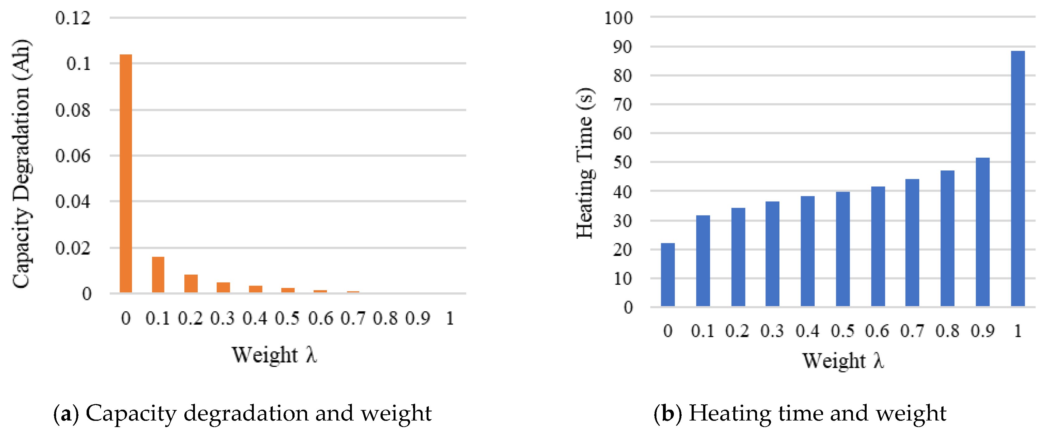
| Weight λ | Total Capacity Degradation (Ah) | Total Heating Time (s) |
|---|---|---|
| 0 | 0.10382248997655331 | 22.17 |
| 0.1 | 0.015977581179648 | 31.71 |
| 0.2 | 0.008228069218434 | 34.37 |
| 0.3 | 0.005059519498740 | 36.44 |
| 0.4 | 0.003253444981261 | 38.21 |
| 0.5 | 0.002482205828299 | 39.63 |
| 0.6 | 0.001690907963803 | 41.66 |
| 0.7 | 0.001018971640568 | 44.11 |
| 0.8 | 6.450307976452842 × 10⁻⁴ | 47.29 |
| 0.9 | 3.382935945904038 × 10⁻⁴ | 51.65 |
| 1 | 3.936906849750717 × 10⁻⁷ | 88.34 |
| Weight λ | 0 | 0.1 | 0.2 | 0.3 | 0.4 | 0.5 | 0.6 | 0.7 | 0.8 | 0.9 | 1 |
| Energy Loss (%) | 6.28 | 7.52 | 7.81 | 8.02 | 8.19 | 8.36 | 8.54 | 8.73 | 8.99 | 9.43 | 12.072 |
Disclaimer/Publisher’s Note: The statements, opinions and data contained in all publications are solely those of the individual author(s) and contributor(s) and not of MDPI and/or the editor(s). MDPI and/or the editor(s) disclaim responsibility for any injury to people or property resulting from any ideas, methods, instructions or products referred to in the content. |
© 2025 by the authors. Licensee MDPI, Basel, Switzerland. This article is an open access article distributed under the terms and conditions of the Creative Commons Attribution (CC BY) license (https://creativecommons.org/licenses/by/4.0/).
Share and Cite
Han, S.; Li, C.; Ding, J.; Gao, X.; Li, X.; Zhang, Z. An Improved PSO-Based DC Discharge Heating Strategy for Lithium-Ion Batteries at Low Temperatures. Energies 2025, 18, 2261. https://doi.org/10.3390/en18092261
Han S, Li C, Ding J, Gao X, Li X, Zhang Z. An Improved PSO-Based DC Discharge Heating Strategy for Lithium-Ion Batteries at Low Temperatures. Energies. 2025; 18(9):2261. https://doi.org/10.3390/en18092261
Chicago/Turabian StyleHan, Shaojian, Chengwei Li, Jifeng Ding, Xinhua Gao, Xiaojie Li, and Zhiwen Zhang. 2025. "An Improved PSO-Based DC Discharge Heating Strategy for Lithium-Ion Batteries at Low Temperatures" Energies 18, no. 9: 2261. https://doi.org/10.3390/en18092261
APA StyleHan, S., Li, C., Ding, J., Gao, X., Li, X., & Zhang, Z. (2025). An Improved PSO-Based DC Discharge Heating Strategy for Lithium-Ion Batteries at Low Temperatures. Energies, 18(9), 2261. https://doi.org/10.3390/en18092261