1. Introduction
The mine shaft hoist is one of the most essential pieces of equipment in mining plants. It is the transport link between the surface and underground parts of the mine. Concerning the type of rope drive (the element that changes the rotational movement into the progressive movement of the vessel in the shaft), hoisting machines are divided into the following categories [
1]:
- ▪
machines with a thrust wheel (Koepe pulley), where the hoisting rope is slung over the Koepe pulley and the movement of the skips/cages hooked to the ends of the rope is achieved by a suitable frictional coupling between the rope and the rope drive;
- ▪
machines with a drive drum, where the rope is wound on the drum when the hoisting vessel is raised and unwound when lowered.
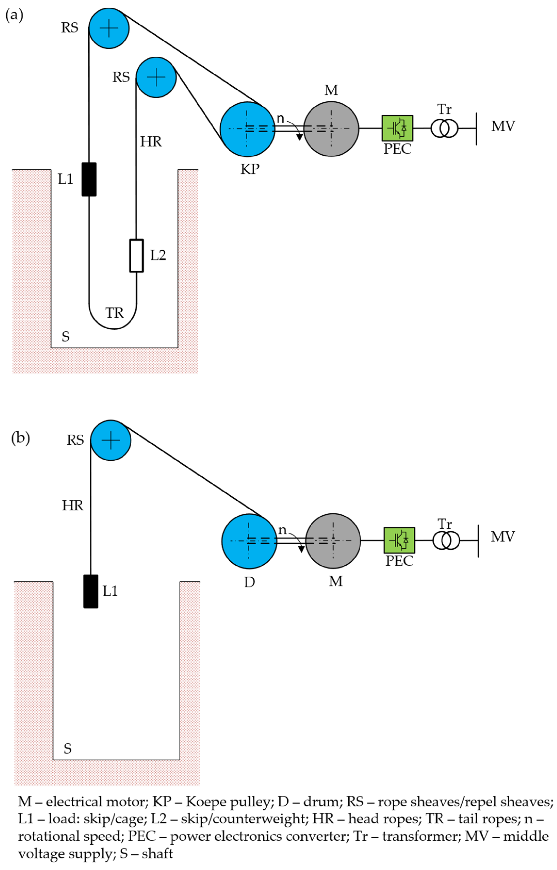
Both types of arrangement are shown in
Figure 1.
The arrangement with the Koepe pulley (
Figure 1a) has the possibility of building multi-rope systems to increase the safety of the shaft hoist operation. The disadvantage is the need for non-destructive testing of the hoisting ropes due to the inability to cut the rope for testing. In addition, in order to balance the forces in the ropes, so-called compensating ropes are used standing and suspended under both vessels. This ensures that the hoist is fully balanced and only the drive can be selected due to the static overweight resulting from the weight of the material/probe/people to be transported.
In addition to the mechanical parts of the drive system, the primary function in this system is the motor and the power electronics used to power and control the drive’s speed. The type of linkage does not matter when selecting the motor. The motor’s parameters are calculated based on the assumed load resulting from the driving diagram. The technical data of the converter and the converter transformer are determined based on the motor rating and the assumed operating conditions.
Due to its important function in the process line, the mine shaft hoist is counted among the basic equipment in mining plant operations. It consists of the following components [
2]:
- ▪
hoisting machine;
- ▪
hoisting vessels (skips, cages);
- ▪
rope sheaves;
- ▪
rope attachments for compensation, guide and buffer ropes;
- ▪
carrier attachments for hoisting vessels;
- ▪
shaft signalling system and communication equipment.
When looking at a mine shaft hoist through the prism of the hoisting machine, the most important thing is the choice of drive motor. This determines the configuration of the hoisting machine’s power (motor-current) circuit and the type of components used (converters, transformers, high-speed circuit breakers, etc.).
More than 90% of hoisting machines in Poland currently use DC motors of the PW series manufactured by DFME. A recent alternative to the DC motor is the alternating current motor (AC motor). This can be either a squirrel-cage induction motor or a synchronous motor. In the case of the former, a gearbox is required. In the case of a synchronous motor, it can be made as a slow-speed motor with a higher number of pole pairs. Regardless of the type of motor used, its power supply is provided by a dedicated static converter system of the appropriate type.
2. Arrangement with DC Motor
Drive systems for hoisting machines with DC motors are built as single- or twin-motor systems. Two-motor systems were used due to the lack of motors with sufficiently high technical parameters such as torque and power rating on the market. After the introduction of the PW 200 motor, the construction of twin-motor systems was no longer justified. It is also not true that twin-motor systems were built because of the possibility of increasing the machine’s safety. Such systems were not designed to operate with a single motor. This may be evidenced by the inability to reconfigure the electrical circuit for single-motor operation. Single-motor operation also requires an appropriate correction of the calculations of the mine shaft hoist in the electrical part. The additional moment of inertia of the rotor of the non-working motor must be included in the calculations. This significantly increases the sum of the masses in motion of such a system and sometimes makes operation with a single-drive motor impossible.
2.1. Single-Motor System
Figure 2 shows a block diagram of a single-motor winding machine drive system with a converter system.
The change of up/down direction is achieved by changing the direction of rotation of the motor, which is the result of a change in the direction of current flow in the excitation circuit. This is implemented through a converter marked C3. The investment cost of the entire system dictated this circuit configuration. The converters marked C1 and C2 are high-power converters with a rated current of more than 1 kA. The excitation converter (C3) is a much lower-power converter, i.e., from a few to several kilowatts, with a current rating of 100 to 250 A. To realise bi-directional energy flow, converters with oppositely connected semiconductor circuits are required, which increases the cost of building such a system. The cost of a converter increases with its power. However, the development of semiconductor components has meant that today, the price difference between single- and double-direction converters is insignificant. In addition, when changing the direction of rotation of the motor by changing the direction of current flow in the primary circuit, the control system of this set-up is simplified. Therefore, systems with so-called reversion through the primary circuit are increasingly common. A schematic of such a system is shown in
Figure 3. C1 and C2 converters are characterised by bi-directional energy flow, as indicated by the arrows, in contrast to the C3 converter, where energy can only flow from the power source to the load—in this case, to the motor excitation circuit.
The systems shown in
Figure 2 and
Figure 3 are 12-pulse systems, a typical arrangement used in winding machine drives. A detailed description of multi-pulse systems can be found in [
3,
4].
Converters C1 and C2 are supplied from separate converter transformers with the appropriate connection group, e.g., Dd0 and Dy11 (30° offset between the secondary side voltages of the transformers). The series connection of the converters ensures that the motor supply voltage level is adequate and the 12-pulse interaction of the drive with the main supply is realised. The ripple amplitude of the output voltage is significantly reduced, and the spectrum of the higher harmonics of the voltage supplying the converters is virtually devoid of harmonics 5 and 7. If one of the C1 or C2 converters fails, the system can operate as a 6-pulse system, i.e., one of the converters is disconnected, and the motor is powered only through the working system. The drive’s speed is limited to half of the rated speed due to a 50% reduction in the supply voltage.
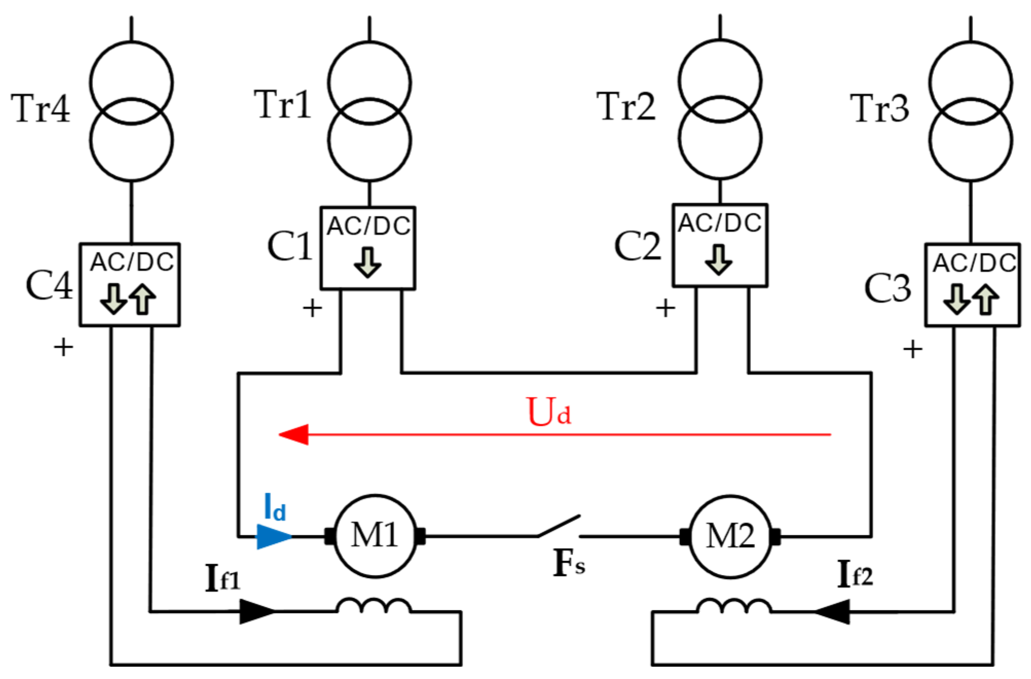
2.2. Twin-Motor System
For very high-power propulsion, twin-motor systems are used, the configuration of which originates in Pung’s system (multi-machine). The use of this system was dictated by the lack of huge motors (above 3.6 MW). This arrangement allowed two motors with correspondingly lower power to be connected on a standard shaft and with a control system ensuring equal loading of both motors.
Figure 4 shows a Pung’s system with two PW series motors and converters.
The construction of such a system is currently not economically and technically justifiable. Suppose that the propulsion power exceeds 6 MW (up to this power value, a PW 200 series motor can be used). In that case, an AC motor should be considered a more economically advantageous solution. The construction of a two-motor system is very costly due to the number of devices in this combination and the consequently greater complexity of the system, control, and protection. The consequence of this is significantly higher operating costs. The efficiency of the drive, which is calculated as a product of the efficiency of the individual components, also decreases. According to reliability theory [
5], the greater the number of devices, the greater the probability of failures.
3. AC Motors Powered by Inverters
When considering the use of AC motors in a hoisting machine drive system, two types of AC motors can potentially be used: the induction motor (squirrel-cage or ring motor) and the synchronous motor [
6,
7,
8]. The ring induction motor is not currently used due to its considerable cost and complex power supply concerning the operating parameters. Cage induction or slow-speed synchronous motors are used in newly built winders.
3.1. Squirrel-Cage Induction Motor
Squirrel-cage induction motors are manufactured as high-speed machines, i.e., their rotational speeds range between 500 and 3000 rpm. This rotational speed of the motor shaft is too high to make it possible to use it in the direct drive of a hoisting machine. Due to its design, it is not possible to construct a low-speed cage machine. Despite these disadvantages, squirrel-cage induction motors are used to drive winding machines thanks to a mechanical gearbox. The undoubted advantages of these motors are their production over an immense power and speed range and their durability.
The efficiency of induction motors currently available on the market reaches 96%, which is a considerable advantage compared with DC motors, which have efficiencies of the order of 90% [
9,
10,
11].
3.2. Slow Synchronous Motor
A synchronous motor is an AC machine in which the rotor rotates at the same speed at which the field generated by the three-phase stator winding rotates. Unlike an induction motor, in which there is slippage which is a measure of the ‘lagging’ of the short-circuited rotor relative to the rotating field, in a synchronous motor, energy must be supplied to the excitation circuit (the rotating part connected to the motor shaft). In the case of hoisting machine drive motors, the excitation circuit’s energy is provided from an external source, an AC/DC converter.
In the classic synchronous motor, the fundamental problem was the starting of such a motor. For this purpose, starting cages (asynchronous starting) or external starting machines were used. Such solutions are not feasible in the case of a hoisting machine drive due to the lack of smooth speed control and the problems of generating the correct value of electromagnetic torque. In this case, a system with a large number of pole pairs is used, which reduces the rotational speed, and by using converters, the motor is kept synchronised during start-up. This ensures that the correct drive torque is maintained in the speed range from zero up to the rated speed.
3.3. System with AC Motor and Direct Frequency Converter
The power supply for AC motors requires circuits that allow the infinitely variable speed control of the drive. Such systems built based on semiconductor components have led to a very rapid development of AC drive systems, successfully eliminating drives with DC motors. AC motors have also been successfully used in hoisting machines. In the case of AC motors, indirect or direct inverters are used to power and regulate their speed [
7]. The two systems are fundamentally different due to the number of stages of variation of the supplied voltage.
Figure 5 shows squirrel-cage induction and synchronous motors powered by a direct frequency converter called a cycloconverter.
The cycloconverter circuit consists of PC1, PC2, and PC3 converters in both cases. In the synchronous motor, a controlled rectifier PCEX supplies the excitation circuit.
The operation of the cycloconverter is based on changing the frequency of the motor supply voltage, which has a direct effect on the smooth regulation of the motor speed according to Equation (1)
where
ns—rotational speed of the field generated in the stator;
fs—frequency of supply voltage (controlled by the cycloconverter);
p—number of pole pairs.
Thus, speed control in both directions is achieved over a wide range for generator and motor operation. Therefore, the mechanical characteristics of the drives in all four quadrants of the speed and torque axis system can be shaped. The system can operate as a motor or generator in any direction of rotation.
When using cycloconverters, the main problem is the output frequency of such a system. As standard, AC motors are built to be powered at 50 Hz. Typically, cycloconverters are built for an output voltage frequency of 15 Hz. This is due to the need to maintain a suitable ratio between the input and output frequency of the cycloconverter. Due to the modulation of the 50 Hz voltage waveform by the control signal, it is recommended that the output frequency should not be greater than one-third of the input frequency—in this case 50 Hz, resulting in a maximum output frequency value of 1.33 Hz.
Consequently, there is a natural reduction in motor power due to the significant reduction in voltage in proportion to the decrease in frequency. The loss of drive power relative to rated conditions forces an oversizing of the system, which is an obvious disadvantage of this solution. The second disadvantage of this system is its impact on the mains supply. This negative effect of the cycloconverter is particularly noticeable in terms of reactive power. Due to its design, the cycloconverter consumes reactive power, which poses a serious problem regarding charges imposed by the distribution system operator. The limiting parameter is tgφ = 0.4. When this is exceeded due to the operation of the equipment, penalties are imposed on the consumer as specified in the connection contract. For this reason, appliances must operate in such a regime where the limit value is not exceeded excessively.
3.4. System with AC Motor and Indirect Frequency Converter
An indirect frequency converter is a design in which there is a double change in the energy parameters transferred from the grid to the load or from the load to the source.
Figure 6 shows block diagrams of drive systems with indirect frequency converters, squirrel-cage induction, and synchronous motors.
Converters PC1 and PC2 are bi-directional AC/DC circuits that perform the rectifier (PC1) roles in the system and the inverter (PC2) in the case of motor operation of the drive system. The machine’s generator operation is realised when PC2 operates as a rectifier and PC1 as an inverter.
The capacitor between the converters PC1 and PC2 constitutes the DC link circuit. Thanks to this system design, it is possible to reduce the system’s negative impact on the mains through suitable control algorithms for the PC1 converter. So-called enhanced power factor (PFC) systems are currently used as PC1, which makes the entire drive system a purely resistive load for the mine’s electrical network. There is no angular offset between the supply current and voltage indication. In the case of DC motors, the only way to reduce the impact on the mains was to use multi-pulse systems, which did not have the same measurable effect as PFC systems [
12].
4. Analysis of the Technical Parameters of DC and AC Motors Used in Hoisting Machines
Table 1 summarises the basic parameters for the four motors. These motors meet the criteria defined for the selected design process. The primary criterion was the motor’s rated torque, which could not be less than 480 kNm.
For comparison, motors used in the hoisting machinery drive were selected, and the selection procedure was carried out for a specifically selected mining shaft hoist. Both DC and AC motors were analysed. Mine crews’ preference for the motor type was ignored during the analysis. DC motors were analysed because of their production in Poland and high popularity among designers and mine employees.
During the design process, the motor is selected for its operating parameters—power and torque on the motor shaft. These two parameters result from the mass transported in the hoisting vessel and from the design of the mine shaft hoist itself, i.e., the depth of the shaft, the mass of the vessels, wheels, and ropes, i.e., generally, the masses in motion. Let us analyse the masses in progressive and rotational motion. Ideally, the rotor mass, and therefore the rotor moment of inertia of the hoisting motor rotor, should be as small as possible [
13,
14,
15,
16].
Evaluating the different motor types regarding technical parameters is essential for assessing investment costs (CAPEX) and determining their subsequent operation (OPEX) [
17,
18].
To select a hoisting motor combining technical and economic data, the equation proposed by the authors can be used:
where
Mmax—maximum torque [kNm];
MN—rated torque [kNm];
hk—number of hours needed for maintenance (brush changes);
PN—rated power [kW];
c—price [mln PLN];
J—rotor’s moment of inertia [kgm2];
m—mass of motor [kg];
η—efficiency [%].
Thus, analysing the results in
Figure 7, it can be concluded that separately excited DC motors, marked A and B, have significantly worse parameters than C and D motors. The rated parameters of torque, moment of inertia, maximum torque, and the power of individual motors were converted per 1 kW of power or per 1 kg of motor mass. This approach makes it possible to compare the motors despite the non-significant differences in the rated parameters.
By analysing the individual parameters, it can be concluded that the D motor is the right choice. The particular technical parameters have an impact on the subsequent operation of the motor. Thus, a lower moment of inertia means that less energy is required to accelerate and decelerate the mass. For example, the choice of a motor with a lower moment of inertia has a further impact when carrying out system upgrades in Poland. The regulations in force do not allow for increasing the masses in motion in retrofitted systems. This means that when carrying out a system modernisation aimed at increasing the mining capacity of a plant, it is necessary to reduce the masses in motion, i.e., to transfer the mass from components such as rope wheels, motor rotors, or rope drives to the useful mass transported in the vessel.
One of the machines with a separately excited DC motor was analysed. According to the documentation of this mining shaft hoist, the assumed capacity was 40 skips/h. The skip load capacity was equal to 15 Mg. The transport of excavated material was not only coal but also waste rock. It is assumed that only 70% [
19] of the extracted spoil is pure saleable coal. In this case, it was 10.5 Mg, which gives an hourly capacity of 420 Mg/h. The records from the hoist machine’s operating recorder were analysed to check the actual hourly capacity of the hoist. The average extraction was 30 skips/hour, i.e., the hourly capacity was 315 Mg/h.
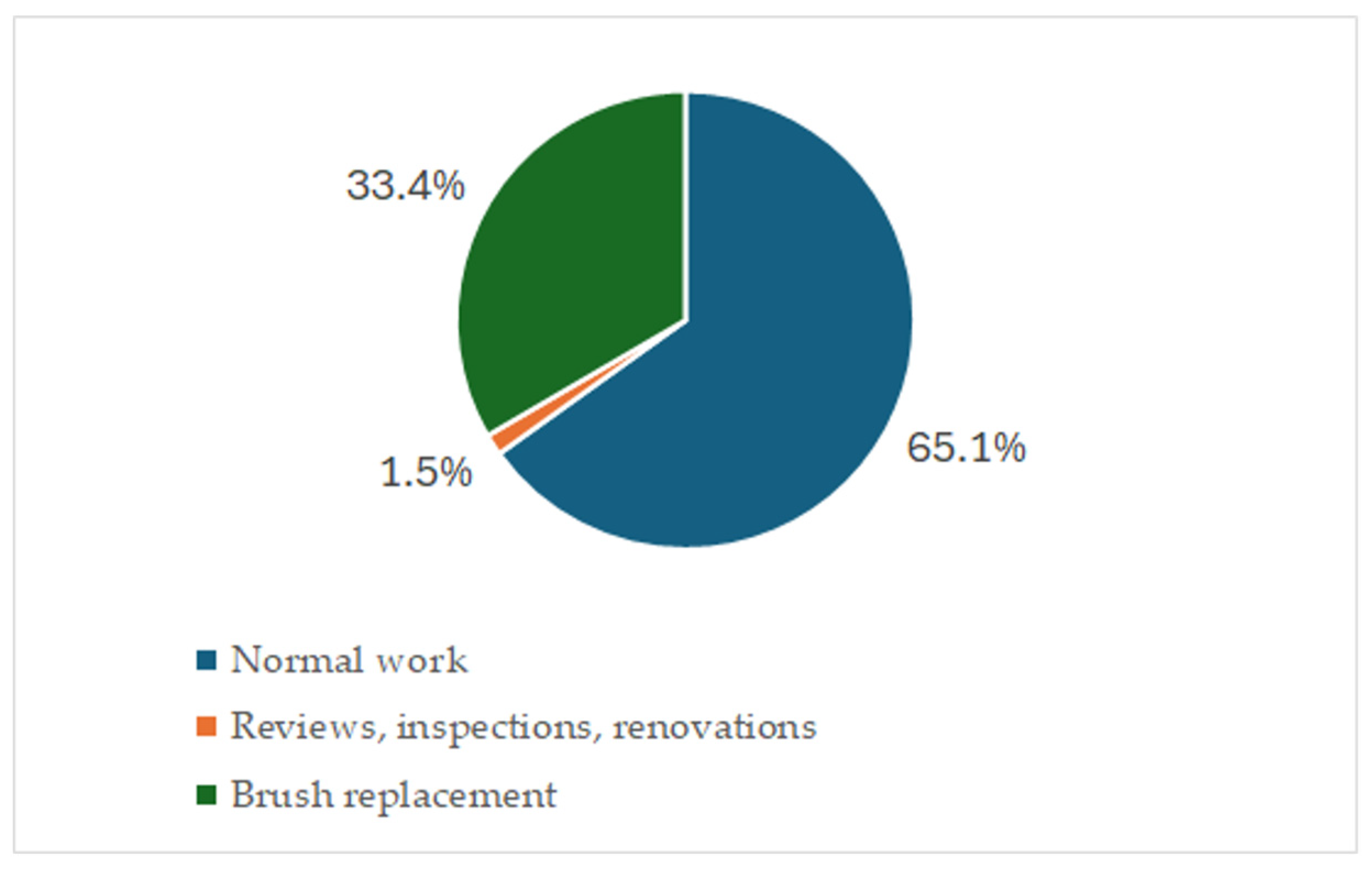
According to the daily operating schedule of the hoist [
20], the time allocated to haulage (adequate working time) was two working shifts (2 × 8 h) five days a week. The remaining time was scheduled for all inspections, checks, and necessary planned and unplanned work (repairs, maintenance and overhaul) [
21]. The time foreseen for replacing the electrographite brushes of the hoisting machine was 96 h/year, or an average of 2 h per week. The average weekly operating time of the hoisting machine is shown in
Figure 8.
5. Economic Analysis of the Use of DC and AC Motors in Hoisting Machines
Considering the technical findings in
Section 4, a financial and sensitivity analysis was drawn up in a purpose-built model. To obtain comparable results for all analysed solutions, a fundamental assumption was made that ore availability for transport is fixed. The model was built based on fixed prices, and the discount rate was assumed to be 4%, a standard rate used in the industry for such analyses. In addition, the model assumed the following:
a fair and equal useful life of 20 years for all motor types;
an initial investment value that represents the total value of the motor, all accessories, and installation costs (CAPEX);
discounted market salvage value [Residual Value], which refers to the estimated value of the motor at the end of its useful life.
5.1. Financial Analysis
When calculating the NPV indicator [
17] for the hoisting machine motor, the part of the indicator relating to revenue remains the biggest problem. Attributing the total revenue of the mining plant to the hoisting machine is incorrect as it is only one part of the production sequence. Determining a percentage of all assets to estimate allocating a part of the total revenue will lead to different results. The reason for this is that there are significant differences in the size of the assets of the individual mines due to the technical solutions adopted to suit the different mining and geological conditions. For this reason, differential analysis was used to calculate the revenue part of the NPV indicator. The calculation of the total indicator is presented in Equation (3)
where
r—discount rate;
n—lifetime.
In terms of the data making up the operating costs (OPEX) associated with the operation of the hoisting machinery, the difference is the cost of electricity consumed to transport the same amount of ore by machines with particular motors. Additional costs that differentiate the hoisting machine motors analysed are the costs associated with the maintenance of the equipment, consisting of the cost of human labour, the materials consumed, and the third-party services used which are necessary for periodic inspection and overhaul. The downtime induced by this work contributed to the lost revenue costs per year [LOSS], representing, for DC motors, between 37% and 38% of the discounted lifetime costs. These translate into a TCO [total cost of ownership] value representing the total discounted lifetime costs of the motors. The calculation of the indicator is given in Equation (4).
In general, the TCO value [
18] for AC motors represents, on average, 58% of the TCO generated by DC motors, which means that the total cost of ownership of AC motors is significantly lower, taking into account CAPEX and discounted OPEX, LESS, and Residual Value over the lifetime of the motors. This significant difference is mainly due to the presence of the lost revenue cost [LOSS] component in the calculation of the indicator for DC motors, which represents between 36.99% and 37.70% of the TCO indicator value, and the absence of this component in the calculation of the TCO indicator for AC motors. The next most weighted component on the TCO value is the amount of the discounted operating costs (OPEX). The calculated value of discounted operating costs (OPEX) for DC motors is 5.8 % to 9.4 % higher than those for AC motors. In the TCO structure, the discounted operating costs for DC motors were between 59.46% and 60.74% of the total indicator.
Due to the absence of the LOSS component in the TCO calculation for AC motors, its structure indicates a predominance of discounted operating costs (OPEX), representing between 95% and 96% of the TCO value. This means that this component has the most significant impact on the size of the total cost of ownership and should primarily be taken into account when selecting a motor. The discounted operating costs for DC motors are between 59.5% and 60.7% of the TCO structure. A significant share of the total cost of ownership indicator structure should lead to minimising operating costs and, thus, a lower TCO. In the analysis, the D motor achieved the lowest TCO value, which is the most desirable outcome and lower than the TCO of the C motor by 1.57%.
The share of CAPEX volume in the TCO calculation ranged from 2.36% to 4.79%, while the discounted Residual Value volume share ranged from 0.09% to 0.22%. These two components should not be significant when selecting a hoisting machine motor.
5.2. Sensitivity Analysis
A sensitivity analysis to a ±15% change in electricity prices resulted in a 53% to 62% change in TCO valuation in favour of AC motors. The sensitivity analysis to a ±15% change in coal prices only affects the LOSS components to which DC motors are sensitive. A 15% change in the price of coal resulted in a change in TCO from 5.5% to 5.8%.
A sensitivity analysis of the net present value of the investment (NPV) performed for changes in electricity prices and changes in coal prices (±15%) also confirmed that the recognition of reduced revenues resulting from the necessary downtime of the DC motors had the most significant impact on the indicator. Lower discounted operating costs for AC motors also translate into higher NPVs.
The difference between machine D and C represents 2.13% in favour of motor D. For the sensitivity analysis to a ±15% change in electricity prices, the difference in NPV between the AC motors reached a range of 2.80% to 1.67% in favour of motor D. The NPV sensitivity analysis to a ±15% change in coal prices also reached 3.29% to 1.57% in favour of motor D.
The magnitude differences between DC motors A and B in the NPV indicator are minimal. They are due to motor A’s lower electricity consumption relative to motor B, whose discounted operating cost value more than compensates for motor B’s slightly higher investment costs.
6. Discussion
Based on the analysis of technical parameters, it was concluded that the motor marked D was the best motor selected for the study. However, in addition to the technical analysis, it is necessary to determine the purchase and operating costs.
When assessing operating costs, one criterion is the maintenance and overhaul specified in the motor’s technical and operating documentation. In addition to periodic maintenance, DC motors need to have their brushes changed and their commutator cleaned. This is in contrast to only periodic maintenance for AC motors.
Of course, there are organisational possibilities to move the brush replacement work to non-working days. Still, when planning an investment to build or replace a hoisting machine, it cannot be assumed that it will only work five days a week due to the need to increase the machine’s effective operating time.
The calculated NPVs for all motors reached positive values. A higher NPV means a more profitable investment. The order of investment selection from highest NPV to lowest is as follows:
D > C > A > B
The calculated TCO values for DC motors are significantly higher than the TCO of AC motors, representing only 58% of their value on average. A lower TCO value means cheaper device use over its entire useful life cycle. The order of investment selection from lowest TCO values to highest is as follows:
D > C > A > B
For the two indicators adopted in the financial analysis, the best investment choice is AC motor D, followed by the second AC motor C. DC motors have lower net present values and a higher total cost of ownership.
From the analyses, it is clear that the D motor obtained the best results for the assumed needs, i.e., the specified technical parameters of the hoisting machine. This article does not state that this motor has the best techno-economic parameters of all the motors, but only for this one case. In each case, the choice of motor will require careful analysis from both the technical and economic sides.
7. Conclusions
The motor is the most critical component of the hoisting machine drive system. Its performance and operating parameters determine the entire mine shaft hoist’s operational safety and efficiency. It should be noted that in most underground mines, two or three mine shaft hoists are available for transporting crew and ore. The hoisting machines are among the equipment which has a very long service life and are relatively rarely replaced due to technical wear and tear and the availability of new technology. It is, therefore, essential to decide on the type of motor prudently and to analyse both technical and economic aspects.
The analysis shows that the choice of AC motor (D motor) is justified from both technical and economic perspectives. In addition to the issues presented in the article, the choice of motor type determines the configuration of the entire drive system.
The reduction in investment costs is mainly due to the absence of additional devices to reduce the negative impact of the hoisting machine system on the mine’s main supply.
Improvements in operating conditions are realised by the following:
- ▪
reduction in electricity demand;
- ▪
increasing the efficiency of the whole system (no additional components, e.g., reactive power compensators);
- ▪
elimination of machine elements requiring special supervision and maintenance (no commutator);
- ▪
no additional elements are subject to periodic checks and inspections, e.g., fast circuit breakers, reactive power compensators, and higher harmonics filters.
Unfortunately, little information can be found in the literature on selecting a motor for a winding machine and its potential benefits or losses. As can be concluded from this analysis, the choice of the motor determines the design of the entire electrical system. This translates into both investment and operating costs for the entire machine.


