
Enhancing CO2 Capture Efficiency: Advanced Modifications of Solvent-Based Absorption Process—Pilot Plant Insights
 , , , , ,
Abstract
1. Introduction
2. Materials and Methods
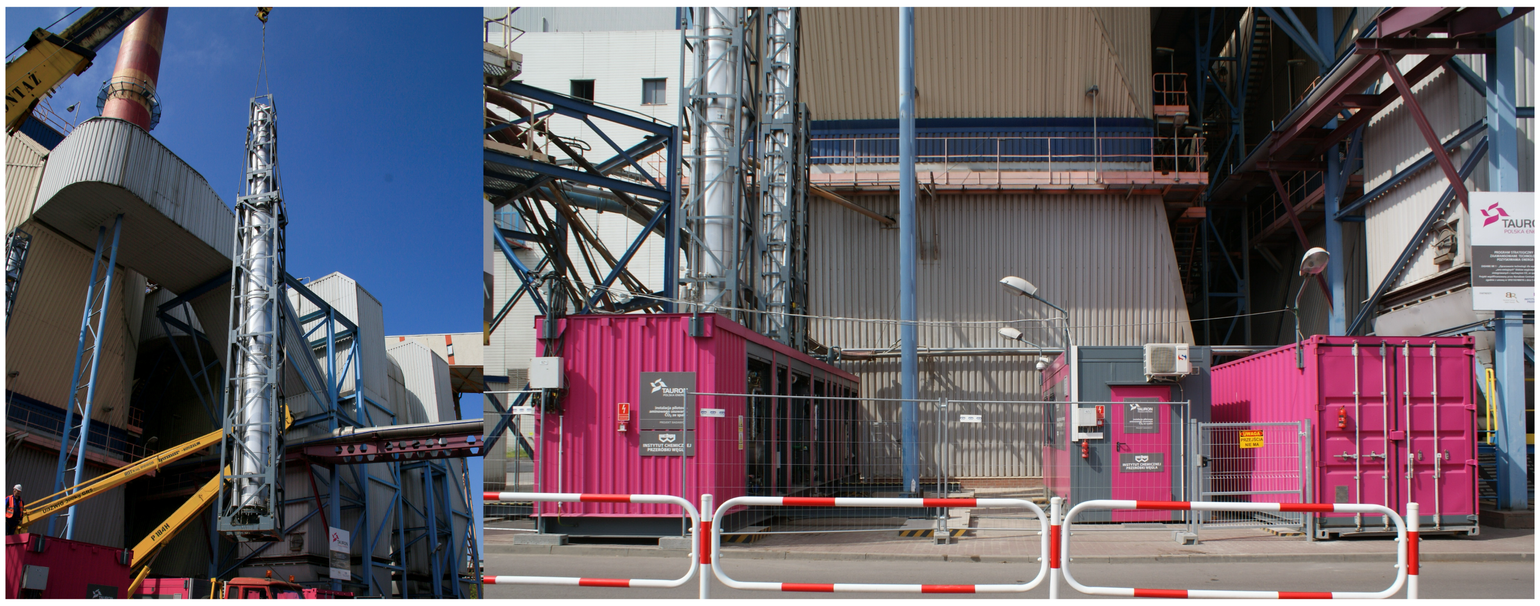
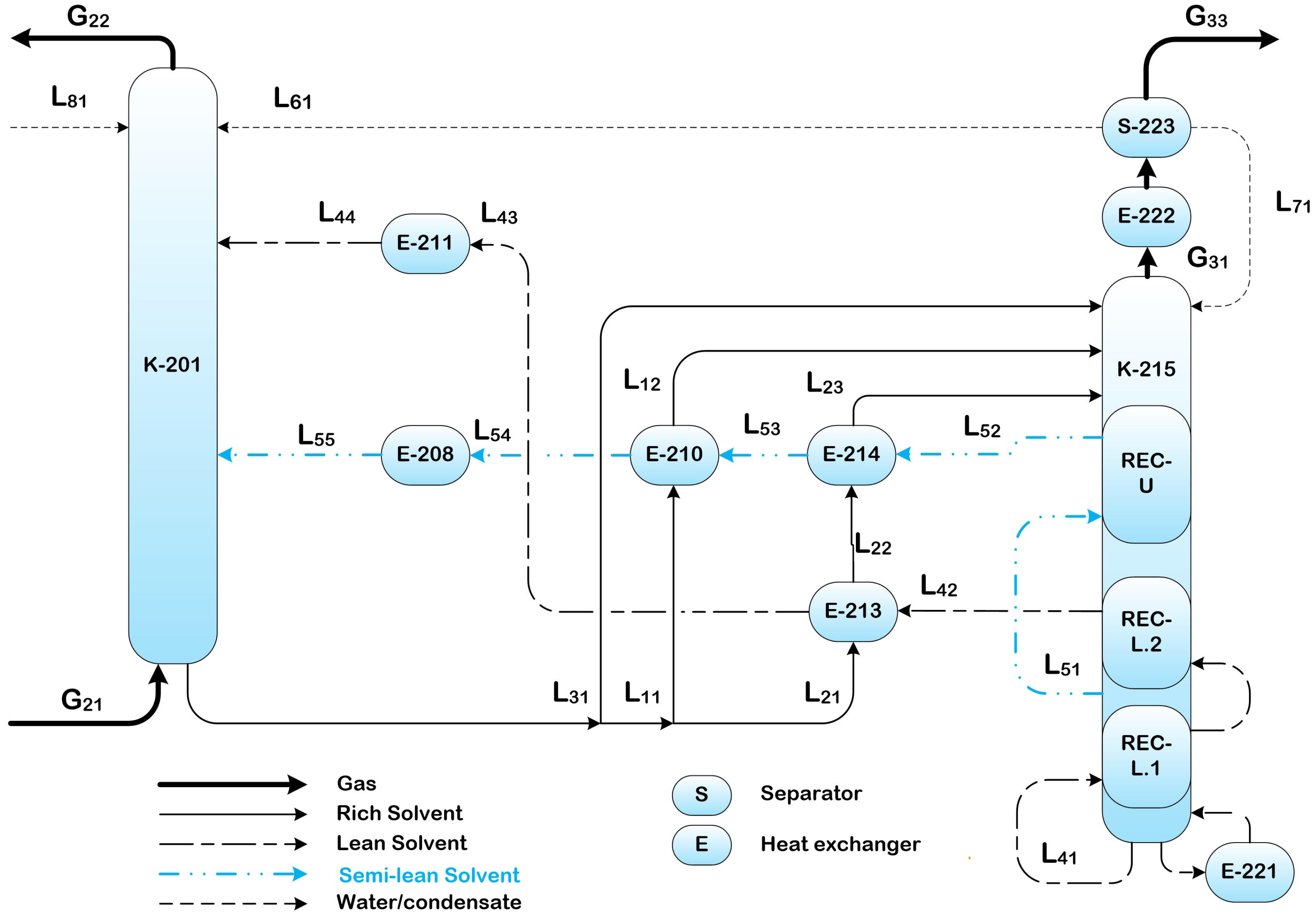
2.1. The Pilot Plant
2.2. Main Apparatus
2.3. Andvanced Proces Configurations
2.3.1. Standard Configuration with Cold Solvent Split (CSS)
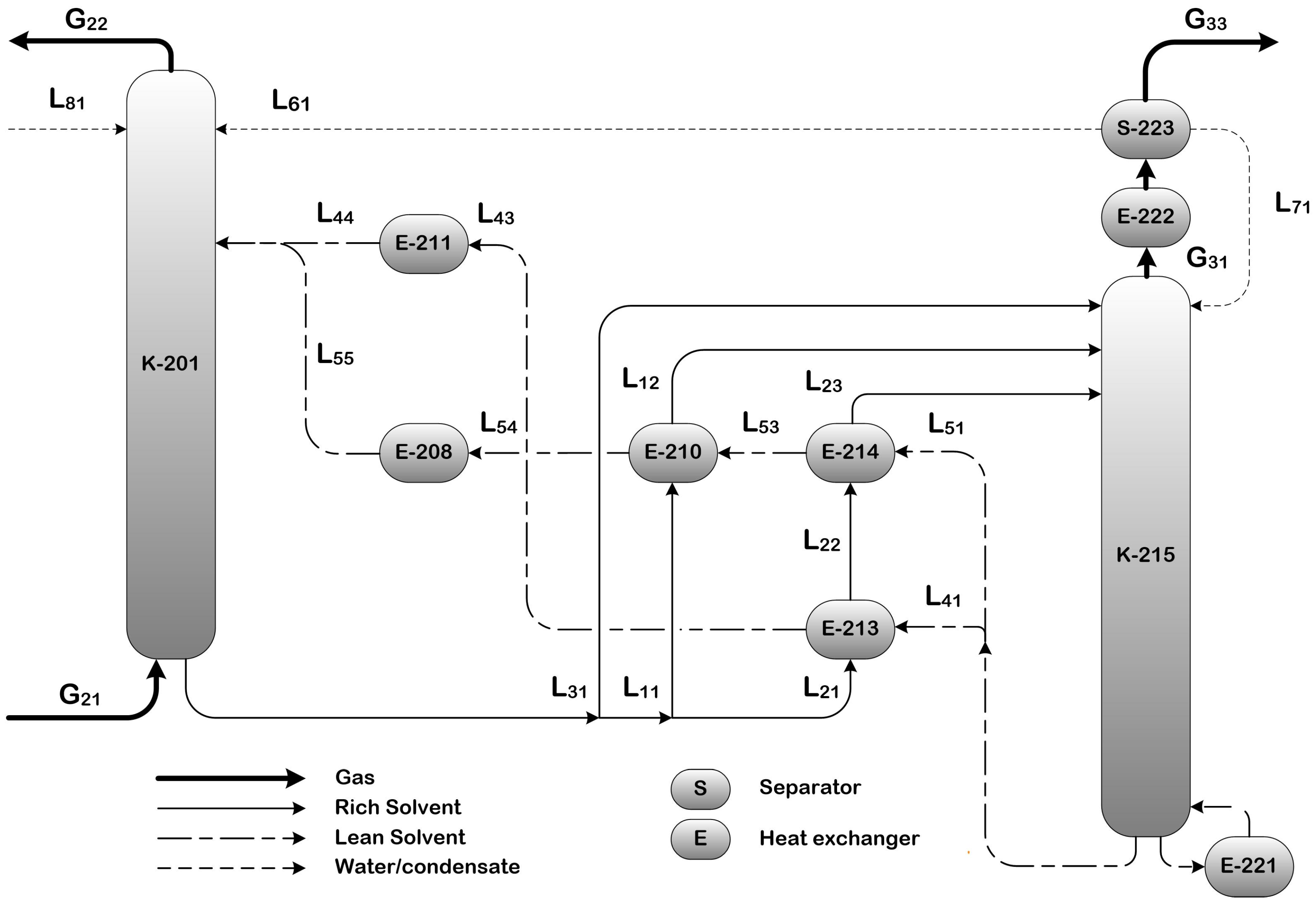
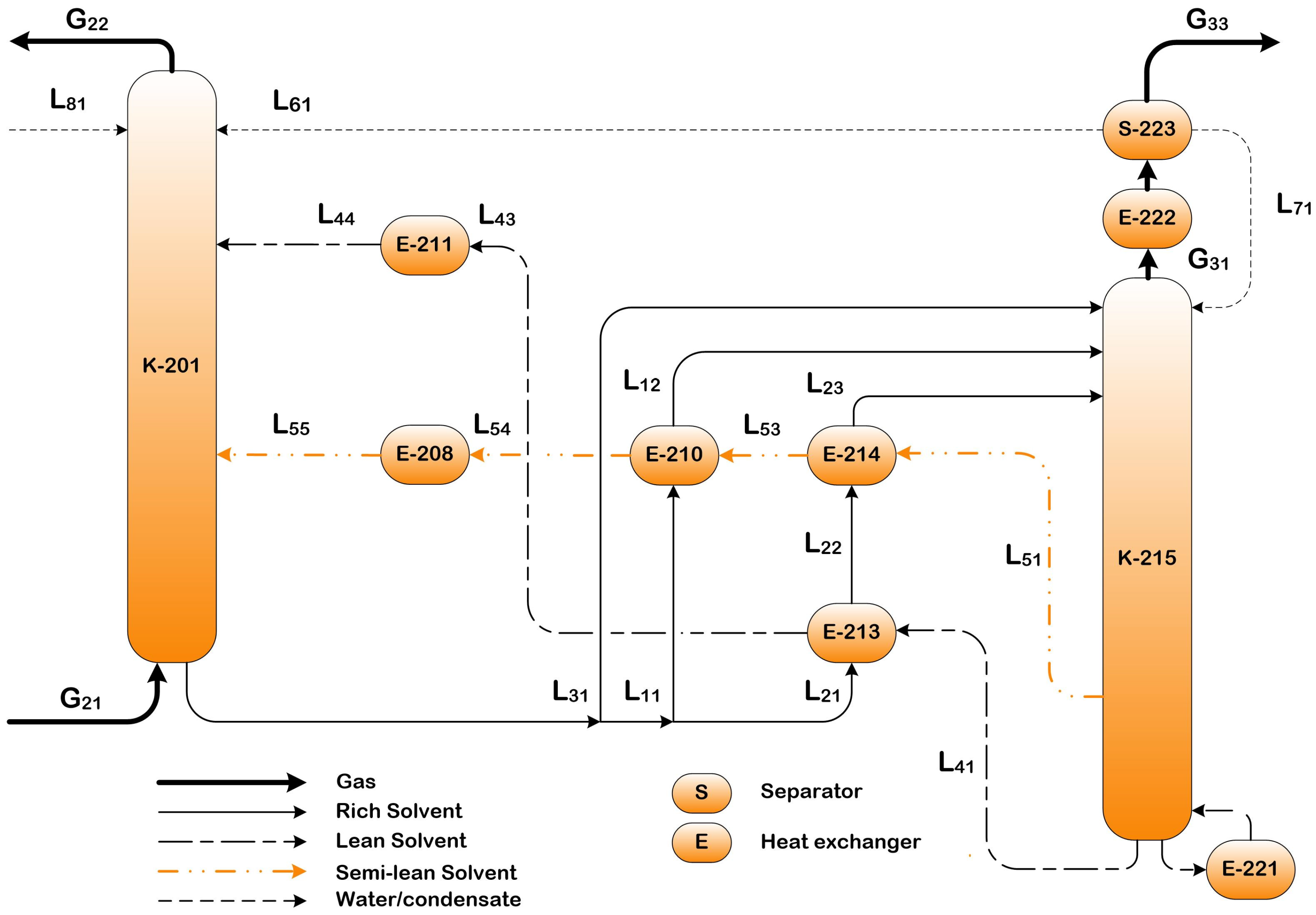
2.3.2. Split Flow (SF)
2.3.3. Split Flow with Heat Integrated Stripper (SF-HIS)
2.4. Main Proces Indicators
2.4.1. CO2 Capture Efficiency
2.4.2. Reboiler Heat Duty
- Heat of Desorption (Qdes)—Represents the minimum energy required to break the chemical bonds between CO2 and the amine solvent, enabling solvent regeneration. In CO2 capture studies [47,48,49,50], it is often assumed that the heat of desorption equals the heat of absorption, although this depends on the solvent composition. In this study, the heat of absorption value was adopted based on Bruder et al. [51].
- Heat of Vaporization (Qvap)—Energy associated with solvent evaporation, primarily water. Some water exits the system with the desorbed CO2, and the heat required for its vaporization is lost. The amount of water leaving the stripper in this manner depends on process parameters, including stripper operating pressure and temperature, solvent composition, and CO2 loading. Higher desorption temperatures and lower solvent CO2 loadings generally increase water vaporization losses.
- Sensible Heat (Qsens)—Represents the energy required to raise the temperature of the solvent entering the desorption system. Its magnitude depends on the temperature difference between the inlet and outlet solvent streams and the specific heat capacity of the solution. In this study, the specific heat capacity of a MEA 30 wt.% solvent was determined using data from Hilliard [52].
- Stripper heat loss (Qloss.S)—Heat dissipation from the stripper, influenced by factors such as design, insulation quality, number of connection points, instrumentation, and the surface-area-to-volume ratio of flowing media (scale effect).
- Exchanger heat loss (Qloss.E)—Heat loss occurring in heat exchangers and other process equipment, including measurement devices and piping between the stripper and cross-flow heat exchangers. The extent of this loss depends on the complexity and the scale of the plant.
- Heat lost in coolers (Qloss.C)—This occurs when the lean solvent is not sufficiently cooled due to inadequate heat exchange in cross-flow heat exchangers, leading to excess heat removal in coolers. Such a situation is more likely in research facilities where varying process configurations are tested, causing deviations from nominal design parameters. However, this type of heat loss does not occur in properly designed industrial systems operating near their design specifications. For this pilot-scale installation, a maximum acceptable (and not counted as a loss) temperature difference between the lean and rich solvent at the outlet of the cross-flow heat exchangers was set at 7 °C.
- The actual heat input required for solvent regeneration, considering all losses, is given by Equation (4):
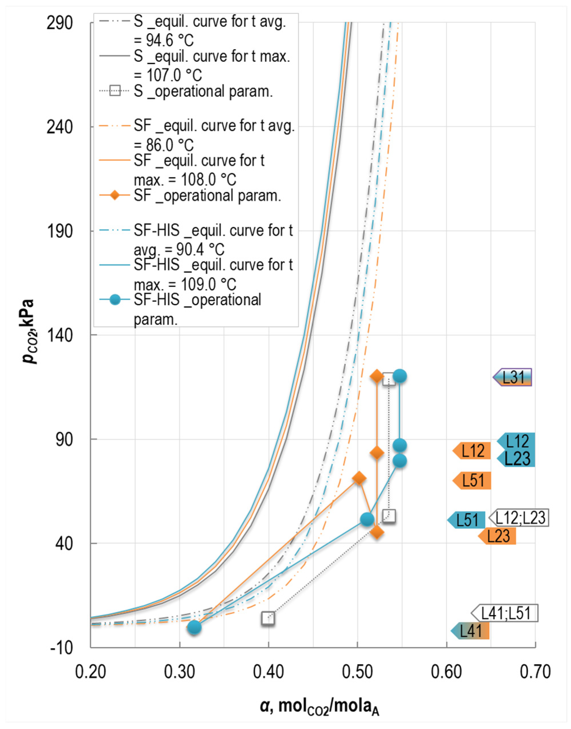
2.4.3. CO2 Loading
3. Results
3.1. Effect of the SF Configuration
3.1.1. Impact on the Absorber
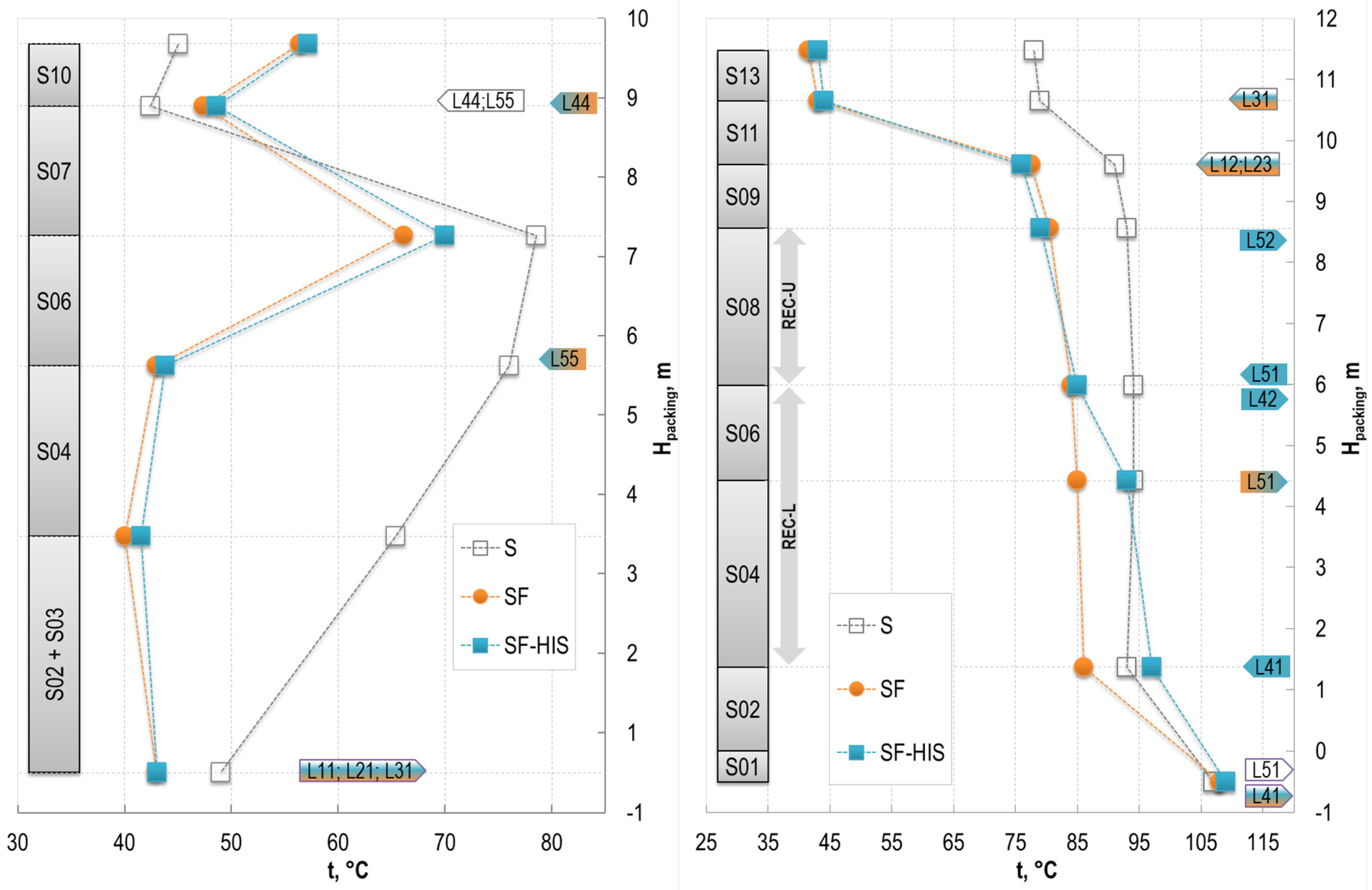
3.1.2. Impact on the Stripper
3.2. Impact of HIS Implementation on Process
3.2.1. Upper Sections of the Stripper Performance
3.2.2. Lower Sections of the Stripper Performance
3.2.3. Impact of HIS on Heat Losses
4. Discussion
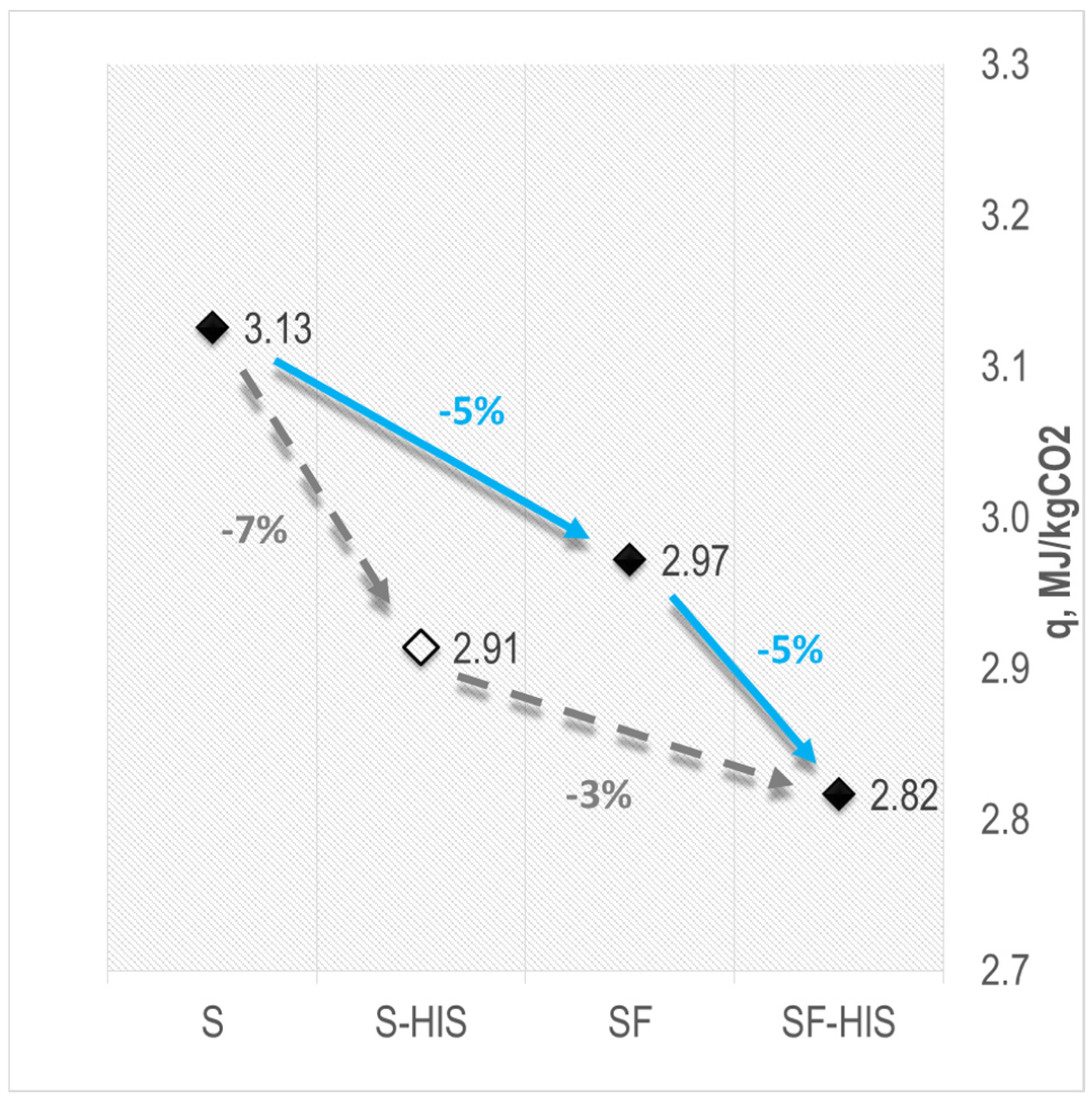
4.1. Reduction in Process Heat Demand
4.2. Reduction in Heat of Vaporization
4.3. Reduction in Sensible Heat
- A dual pumping system for lean and semi-lean solvents;
- Modification of the stripper to allow semi-lean solvent extraction;
- Redesign of the absorber to accommodate changed solvent flows;
- Increased heat exchange surface in cross heat exchangers.
- For the HIS configuration, the modifications include the following:
- Significant modification of the stripper, particularly due to the integration of internal recuperators;
- A slightly increased pumping load for the lean solvent.
4.4. Comparison with Literature Data
5. Conclusions
Author Contributions
Funding
Data Availability Statement
Acknowledgments
Conflicts of Interest
Nomenclature
| BECCS | Bio-energy with Carbon capture and storage |
| c(n_i) | concentration of the component ‘i’ in gas stream ‘n’ (dry basis), %vol. |
| C% | amine mass concentration in the CO2 unloaded solvent, %wt. |
| cp | specific heat capacity of the solvent at a given balance point, kJ/kg K |
| CSS | Cold Solvent Split (solvent-based process configuration) |
| D | diameter, mm |
| DAF | Double Absorber Feed (solvent-based process configuration) |
| G(n_i) | gas stream (mass flow rate of the component ‘i’ in ‘n’ stream), kg/h |
| G’ | gas stream (volumetric flow rate), m3/h |
| H | height, mm |
| HIS | Heat Integrated Stripper (solvent-based process configuration) |
| ITPE | Institute of Energy and Fuel Processing Technology |
| L(n_i) | liquid stream (mass flow rate of the component ‘i’ in ‘n’ stream), kg/h |
| L’(n_i) | liquid stream (volumetric flow rate of the component ‘i’ in ‘n’ stream), kg/h |
| MEA | Monoethanolamine (2-aminoethanol) |
| p | pressure, kPa |
| pi | partial pressure of the component ‘i’ |
| PCCC | post-combustion carbon capture |
| q | reboiler heat duty, MJ/kgCO2 |
| qcross | unit heat duty in cross-flow heat exchangers, MJ/kgCO2 |
| qdes | heat of desorption, MJ/kgCO2 |
| qh | reboiler heater duty, MJ/kgCO2 |
| qloss.C | unit heat loss in coolers, J/h, kW |
| qloss.E | unit heat loss in cross-flow heat exchangers, J/h, kW |
| qloss.S | unit heat loss in stripper, J/h, kW |
| qsens | sensible heat of the solvent, MJ/kgCO2 |
| qsens-semi | sensible heat of the semi lean solvent, MJ/kgCO2 |
| qsens-deep | sensible heat of the deep lean solvent, MJ/kgCO2 |
| qvap | heat of vaporization, MJ/kgCO2 |
| Qcross | heat transfer rate in a cross-flow heat exchanger, J/h, kW |
| Qdes | heat flow for desorption, J/h, kW |
| Qh | reboiler heater power setting, kW |
| Qloss.C | heat loss in coolers, J/h, kW |
| Qloss.E | heat loss in cross-flow heat exchangers, J/h, kW |
| Qloss.S | heat loss in stripper, J/h, kW |
| QREC | heat flow through recuperators, J/h, kW |
| Qreg | heat flow for solvent regeneration, J/h, kW |
| Qsens | sensible heat flow, J/h, kW |
| Qvap | heat flow for solvent vaporization, J/h, kW |
| REC-U | upper recuperator of the stripper |
| REC-L | lower recuperator of the stripper |
| RS | Rich Split (solvent-based process configuration) |
| S | Standard (solvent-based process configuration) |
| SF | Split Flow (solvent-based process configuration) |
| SI | Stripper Interheating (solvent-based process configuration) |
| t | temperature, °C |
| u | uncertainty |
| y(n_i) | molar fraction of the component ‘i’ in ‘n’ stream (dry basis), mol/mol |
| α | CO2 loading of the solvent (ratio of the moles of absorbed CO2 to the moles of amine functional groups in the solvent), molCO2/molA |
| ρ | density, kg/dm3 |
| η | CO2 capture efficiency, % |
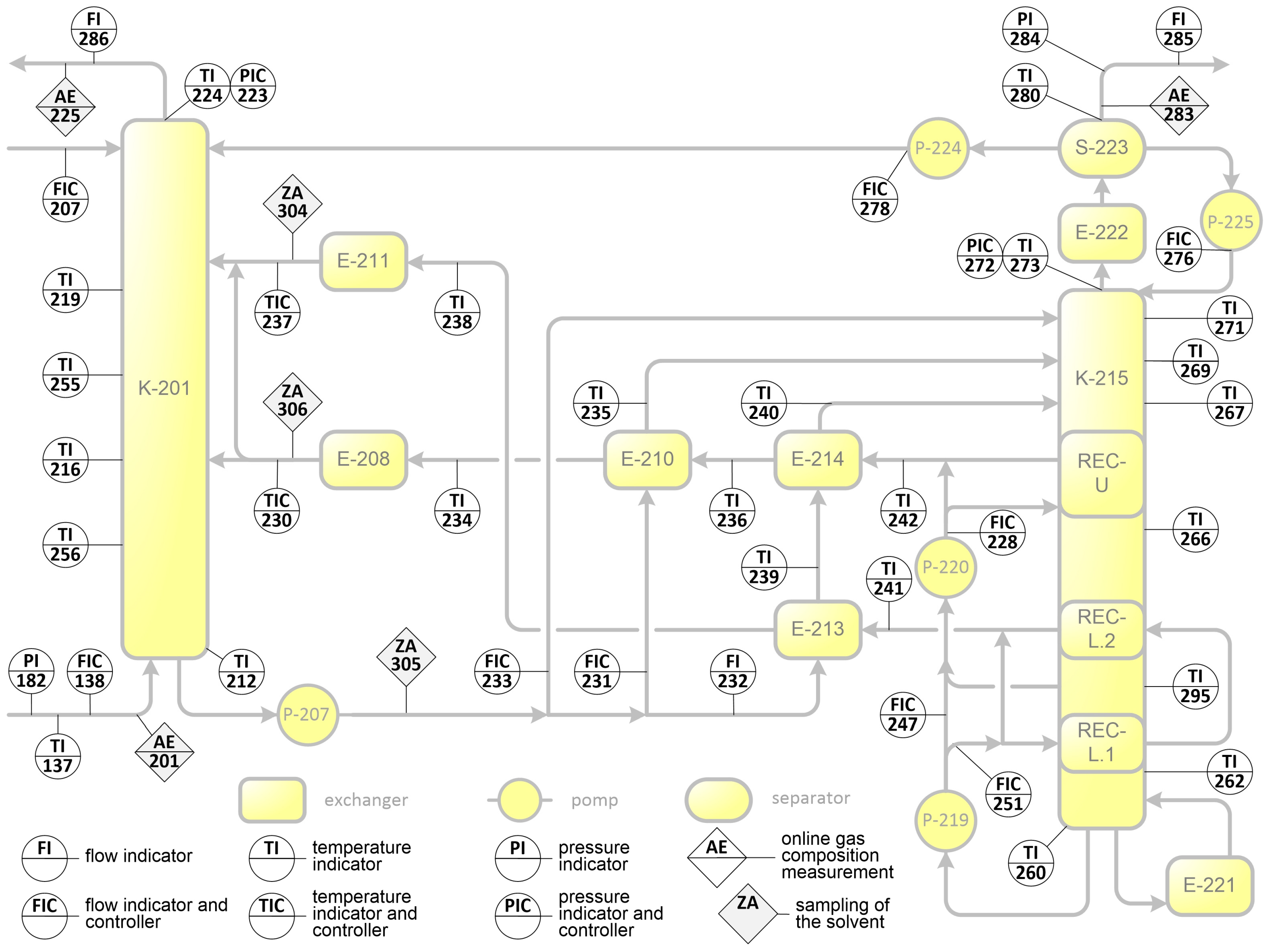
Appendix A
Measurement Scheme of the Pilot Plant
Appendix B
Raw Measurement Data

| Configuration | S | SF | SF-HIS | ||||||
|---|---|---|---|---|---|---|---|---|---|
| Sym. | Measured Parameter | Unit | Meas. no | Value | u | Value | u | Value | u |
| G21 | Absorber inlet flue gas flow | kg/h | FI-138 | 299.7 | 5.9 | 286.5 | 5.9 | 285.6 | 5.9 |
| p21 | Pressure of the absorber inlet flue gas | kPa(g) | PI-182 | 24.6 | 0.1 | 25.0 | 0.1 | 24.8 | 0.1 |
| t21 | Temperature of the absorber inlet flue gas | °C | TI-137 | 29.0 | 1.2 | 32.6 | 1.3 | 30.0 | 1.2 |
| y21_CO2 | The molar fraction of CO2 in the dry inlet flue gas | molCO2/ moldfg | AE-201 | 0.1366 | 0.0017 | 0.1299 | 0.0019 | 0.1305 | 0.0016 |
| y21_O2 | The molar fraction of O2 in the dry inlet flue gas | molO2/ moldfg | AE-201 | 0.0616 | 0.0017 | 0.0689 | 0.0020 | 0.0674 | 0.0016 |
| G22 | Absorber outlet flue gas flow | kg/h | FI-286 | 245.2 | 7.3 | 254.2 | 7.3 | 252.7 | 7.3 |
| p22 | Flue gas pressure at the top of the absorber | kPa(g) | PI-223 | 20.4 | 0.1 | 21.3 | 0.1 | 21.2 | 0.1 |
| t22 | Flue gas temperature at the top of the absorber | °C | TI-224 | 44.9 | 0.8 | 56.0 | 0.8 | 57.1 | 0.8 |
| y22_CO2 | The molar fraction of CO2 in the dry outlet flue gas | molCO2/ moldfg | AE-225 | 0.0412 | 0.0015 | 0.0336 | 0.0017 | 0.0217 | 0.0015 |
| y22_O2 | The molar fraction of O2 in the dry outlet flue gas | molO2/ moldfg | AE-225 | 0.0673 | 0.0018 | 0.0768 | 0.0021 | 0.0756 | 0.0017 |
| G33 | Separator S-223 outlet flue gas flow | kg/h | FI-285 | 40.9 | 0.4 | 39.6 | 0.4 | 45.1 | 0.4 |
| p33 | Outlet gas pressure from the Separator S-223 | kPa(g) | PI-284 | -3.0 | 0.1 | -2.0 | 0.1 | -1.8 | 0.4 |
| t33 | Outlet gas temperature from the Separator S-223 | °C | TI-280 | 29.0 | 1.3 | 25.0 | 1.2 | 25.0 | 1.2 |
| p31 | Gas pressure at the top of the stripper | dm3/h | PI-272 | 30.0 | 0.1 | 29.9 | 0.1 | 30.1 | 0.1 |
| L’11 | E-210 HX-rich solvent inlet flow | dm3/h | FI-231 | 601.0 | 8.8 | 736.0 | 6.6 | 739.2 | 6.9 |
| α11 | CO2 loading of the rich solvent from the absorber | molCO2/ molA | ZA-305 | 0.5436 | 0.0095 | 0.5246 | 0.0091 | 0.5443 | 0.0094 |
| t11 | Temperature of the rich solvent from the absorber | °C | TI-212 | 49.0 | 0.8 | 43.0 | 0.8 | 43.0 | 0.8 |
| t12 | Temperature of the rich solvent to the stripper (sec. 10) | °C | TI-235 | 92.8 | 0.9 | 79.0 | 0.8 | 77.0 | 0.8 |
| C% | Amine concentration in the CO2 unloaded solvent | % | ZA-304 | 33.8 | 1.7 | 32.4 | 1.7 | 32.4 | 1.7 |
| L’21 | E-213 HX-rich solvent inlet flow | dm3/h | FI-232 | 571.1 | 17.8 | 666.1 | 10.7 | 656.7 | 12.6 |
| t22 | Temperature of the rich solvent to the HX E-214 | °C | TI-239 | 97.4 | 1.0 | 97.0 | 0.8 | 81.0 | 0.8 |
| t23 | Temperature of the rich solvent to the stripper (sec. 8) | °C | TI-240 | 100.5 | 0.8 | 95.0 | 0.8 | 81.0 | 0.8 |
| L’31 | Stripper (sec. 12) solvent inlet flow | dm3/h | FI-233 | 100.4 | 1.6 | 125.3 | 1.5 | 124.6 | 1.5 |
| L’41 | Stripper solvent outlet flow | dm3/h | FI-251 | 608.8 | 2.6 | 773.0 | 2.6 | 727.6 | 2.4 |
| α41 | CO2 loading of the lean solvent from the stripper | molCO2/ molA | ZA-304 | 0.3967 | 0.0067 | 0.3150 | 0.0055 | 0.3167 | 0.0055 |
| t41 | Temperature of the lean solvent from the stripper | °C | TI-260 | 107.0 | 0.8 | 108.0 | 0.8 | 109.0 | 0.8 |
| t42 | Temperature of the lean solvent to the HX E-213 | °C | TI-241 | 107.0 | 0.9 | 108.0 | 0.8 | 87.0 | 0.8 |
| t43 | Temperature of the lean solvent to the cooler E-211 | °C | TI-238 | 58.7 | 0.9 | 55.4 | 0.9 | 52.1 | 0.8 |
| t44 | Temperature of the lean solvent to the top absorber | °C | TI-237 | 40.0 | 0.8 | 40.0 | 0.8 | 40.0 | 0.8 |
| L’51 | Stripper (sec. 1/sec. 5) solvent outlet flow | dm3/h | FI-247/ FI-228 | 689.7 | 3.1 | 800.1 | 2.5 | 799.8 | 2.5 |
| α51 | CO2 loading of the lean solvent from the stripper (sec. 1/sec. 5) | molCO2/ molA | ZA-306 | 0.3967 | 0.0067 | 0.5007 | 0.0087 | 0.5118 | 0.0089 |
| t51 | Temperature of the lean solvent from the stripper (sec. 1/sec. 5) | °C | TI-260/ TI-295 | 107.0 | 0.8 | 85.0 | 0.8 | 93.0 | 0.8 |
| t52 | Temperature of the lean solvent to the HX E-214 | °C | TI-242 | 107.0 | 0.8 | 85.0 | 0.8 | 83.4 | 0.9 |
| t53 | Temperature of the lean solvent to the HX E-210 | °C | TI-236 | 99.2 | 0.9 | 86.0 | 0.8 | 83.0 | 0.8 |
| t54 | Temperature of the lean solvent to the cooler E-208 | °C | TI-234 | 59.8 | 0.8 | 51.0 | 0.8 | 51.0 | 0.8 |
| t55 | Temperature of the lean solvent to the mid-section of the absorber | °C | TIC-230 | 40.0 | 0.8 | 40.0 | 0.8 | 40.0 | 0.8 |
| L’61 | Top absorber condensate inlet flow | dm3/h | FI-278 | 7.7 | 0.5 | 0.5 | 0.0 | 0.7 | 0.1 |
| t61 | Temperature of the condensate from the Separator S-223 | °C | TI-280 | 29.0 | 0.9 | 25.0 | 0.7 | 25.0 | 0.7 |
| L’81 | Top absorber make-up water inlet flow | dm3/h | FI-207 | 11.8 | 0.7 | 22.1 | 1.8 | 20.1 | 1.6 |
| t81 | Temperature of the make-up water | °C | Ext. | 12.6 | 0.7 | 17.0 | 0.7 | 17.0 | 0.7 |
References
- Alizadeh, S.M.; Khalili, Y.; Ahmadi, M. Comprehensive Review of Carbon Capture and Storage Integration in Hydrogen Production: Opportunities, Challenges, and Future Perspectives. Energies 2024, 17, 5330. [Google Scholar] [CrossRef]
- Yang, J.; Wang, C.; Xu, D.; Yu, X.; Yang, Y.; Wang, Z.; Wu, X. Study on the Economic Operation of a 1000 MWe Coal-Fired Power Plant with CO2 Capture. Energies 2024, 17, 4986. [Google Scholar] [CrossRef]
- Kopacz, M.; Matuszewska, D.; Olczak, P. Carbon Capture and Storage (CCS) Implementation as a Method of Reducing Emissions from Coal Thermal Power Plants in Poland. Energies 2024, 17, 6342. [Google Scholar] [CrossRef]
- He, S.; Zheng, Y. CO2 Capture Cost Reduction Potential of the Coal-Fired Power Plants under High Penetration of Renewable Power in China. Energies 2024, 17, 2050. [Google Scholar] [CrossRef]
- Strojny, M.; Gładysz, P.; Hanak, D.P.; Nowak, W. Comparative Analysis of CO2 Capture Technologies Using Amine Absorption and Calcium Looping Integrated with Natural Gas Combined Cycle Power Plant. Energy 2023, 284, 128599. [Google Scholar] [CrossRef]
- Vijayan, D.S.; Gopalaswamy, S.; Sivasuriyan, A.; Koda, E.; Sitek, W.; Vaverková, M.D.; Podlasek, A. Advances and Applications of Carbon Capture, Utilization, and Storage in Civil Engineering: A Comprehensive Review. Energies 2024, 17, 6046. [Google Scholar] [CrossRef]
- Christianides, D.; Bagaki, D.A.; Timmers, R.A.; Zrimec, M.B.; Theodoropoulou, A.; Angelidaki, I.; Kougias, P.; Zampieri, G.; Kamergi, N.; Napoli, A.; et al. Biogenic CO2 Emissions in the EU Biofuel and Bioenergy Sector: Mapping Sources, Regional Trends, and Pathways for Capture and Utilisation. Energies 2025, 18, 1345. [Google Scholar] [CrossRef]
- Feron, P. Absorption-Based Post-Combustion Capture of Carbon Dioxide; Woodhead Publishing: Duxford, UK, 2016; ISBN 978-0-08-100514-9. [Google Scholar]
- Le Moullec, Y.; Kanniche, M. Screening of Flowsheet Modifications for an Efficient Monoethanolamine (MEA) Based Post-Combustion CO2 Capture. Int. J. Greenh. Gas Control 2011, 5, 727–740. [Google Scholar] [CrossRef]
- Cousins, A.; Wardhaugh, L.T.; Feron, P.H.M. Preliminary Analysis of Process Flow Sheet Modifications for Energy Efficient CO2 Capture from Flue Gases Using Chemical Absorption. Chem. Eng. Res. Des. 2011, 89, 1237–1251. [Google Scholar] [CrossRef]
- Feron, P.H.M.; Cousins, A.; Jiang, K.; Zhai, R.; Garcia, M. An Update of the Benchmark Post-Combustion CO2-Capture Technology. Fuel 2020, 273, 117776. [Google Scholar] [CrossRef]
- Shoeld, M. Purification and Separation of Gaseous Mixtures. U.S. Patent 1,971,798, 28 August 1934. [Google Scholar]
- Towler, G.; Shethna, H.; Cole, B.; Hajdik, B. Improved Absorber-Stripper Technology for Gas Sweetening to Ultra-Low H2S Concentrations. Proc. Annu. Conv.-Gas Process. Assoc. 1997. Available online: https://www.bre.com/PDF/Improved-Absorber-Stripper-Technology-for-Gas-Sweetening-to-Ultra-Low-H2S-Concentrations.pdf (accessed on 31 January 2025).
- Condorelli, P.; Mariz, C.; Scherffius, J.; Won, R. Split Flow Process and Apparatus 2001. Available online: https://patents.google.com/patent/EP1152815A1/en (accessed on 31 January 2025).
- Freguia, S.; Gilmartin, J.; Reddy, S.; Scherffius, J. Improved Split Flow Process and Apparatus 2004. Available online: https://patents.google.com/patent/WO2004005818B1/en (accessed on 31 January 2025).
- Cousins, A.; Wardhaugh, L.T.; Feron, P.H.M. A Survey of Process Flow Sheet Modifications for Energy Efficient CO2 Capture from Flue Gases Using Chemical Absorption. Int. J. Greenh. Gas Control 2011, 5, 605–619. [Google Scholar] [CrossRef]
- Iijima, M.; Nagayasu, T.; Kamijyo, T.; Nakatani, S. MHI’s Energy Efficiency Flue Gas CO2 Capture Technology and Large Scale CCS Demonstration Test at Coal-Fired Power Plants in USA. Mitsubishi Heavy Ind. Tech. Rev. 2011, 48, 26–32. [Google Scholar]
- Oyenekan, B.A.; Rochelle, G.T. Alternative Stripper Configurations for CO2 Capture by Aqueous Amines. AIChE J. 2007, 53, 3144–3154. [Google Scholar] [CrossRef]
- Wagener, H.D. Stripper Modeling for CO2 Removal Using Monoethanolamine and Piperazine Solvents. Ph.D. Thesis, The University of Texas, Austin, TX, USA, 2011. [Google Scholar]
- Le Moullec, Y.; Neveux, T.; Al Azki, A.; Chikukwa, A.; Hoff, K.A. Process Modifications for Solvent-Based Post-Combustion CO2 Capture. Int. J. Greenh. Gas Control 2014, 31, 96–112. [Google Scholar] [CrossRef]
- Stoffregen, T.; Rigby, S.; Jovanovic, S.; Krishnamurthy, K.R. Pilot-Scale Demonstration of an Advanced Aqueous Amine-Based Post-Combustion Capture Technology for CO2 Capture from Power Plant Flue Gases. Energy Procedia 2014, 63, 1456–1469. [Google Scholar] [CrossRef]
- Li, K.; Cousins, A.; Yu, H.; Feron, P.; Tade, M.; Luo, W.; Chen, J. Systematic Study of Aqueous Monoethanolamine-Based CO2 Capture Process: Model Development and Process Improvement. Energy Sci. Eng. 2016, 4, 23–39. [Google Scholar] [CrossRef]
- Zhao, B.; Liu, F.; Cui, Z.; Liu, C.; Yue, H.; Tang, S.; Liu, Y.; Lu, H.; Liang, B. Enhancing the Energetic Efficiency of MDEA/PZ-Based CO2 Capture Technology for a 650MW Power Plant: Process Improvement. Appl. Energy 2017, 185, 362–375. [Google Scholar] [CrossRef]
- Muhammad, H.A.; Sultan, H.; Lee, B.; Imran, M.; Baek, I.H.; Baik, Y.-J.; Nam, S.C. Energy Minimization of Carbon Capture and Storage by Means of a Novel Process Configuration. Energy Convers. Manag. 2020, 215, 112871. [Google Scholar] [CrossRef]
- Vinjarapu, S.H.B.; Neerup, R.; Larsen, A.H.; Villadsen, S.N.B.; Jensen, S.; Karlsson, J.L.; Kappel, J.; Lassen, H.; Blinksbjerg, P.; von Solms, N.; et al. Pilot-Scale CO2 Capture Demonstration of Stripper Interheating Using 30 Wt% MEA at a Waste-to-Energy Facility. Energy 2025, 320, 134973. [Google Scholar] [CrossRef]
- Rochelle, G.; Gao, T.; Liu, C.-T.; Suresh, A.; Akinpelumi, K.; Chen, E.; Wu, Y. National Carbon Capture Center Work Supported by Carbon Capture Project 4-PZASTM at NGCC Conditions. Appl. Energy 2020, 367, 123416. [Google Scholar]
- Frimpong, R.A.; Nikolic, H.; Bahr, D.; Kiran, G.; Liu, K. Pilot Scale Testing of an Advanced Solvent in a 0.7 MWe Post-Combustion CO2 Capture Unit. Int. J. Greenh. Gas Control 2021, 106, 103290. [Google Scholar] [CrossRef]
- Leites, I.L.; Sama, D.A.; Lior, N. The Theory and Practice of Energy Saving in the Chemical Industry: Some Methods for Reducing Thermodynamic Irreversibility in Chemical Technology Processes. Energy 2003, 28, 55–97. [Google Scholar] [CrossRef]
- Oyenekan, B.A. Modeling of Strippers for CO2 Capture by Aqueous Amines. Ph.D. Thesis, The University of Texas, Austin, TX, USA, 2007. [Google Scholar]
- Salimi, M.; Karimi, V.; Hosseinifard, F.; Amidpour, M. Techno-Economic Study of Different Process Configurations of CO2 Capture by MEA Absorption and Utilization of an MCDM Method for Their Ranking. Energy Rep. 2024, 12, 593–607. [Google Scholar] [CrossRef]
- Løge, I.A.; Demir, C.; Vinjarapu, S.H.B.; Neerup, R.; Jensen, E.H.; Jørsboe, J.K.; Dimitriadi, M.; Halilov, H.; Frøstrup, C.F.; Gyorbiro, I.; et al. Pilot-Scale CO2 Capture in a Cement Plant with CESAR1: Comparative Analysis of Specific Reboiler Duty across Advanced Process Configurations. Chem. Eng. J. 2025, 506, 159429. [Google Scholar] [CrossRef]
- Stec, M.; Tatarczuk, A.; Więcław-Solny, L.; Krótki, A.; Ściążko, M.; Tokarski, S. Pilot Plant Results for Advanced CO2 Capture Process Using Amine Scrubbing at the Jaworzno II Power Plant in Poland. Fuel 2015, 151, 50–56. [Google Scholar] [CrossRef]
- Stec, M.; Tatarczuk, A.; Więcław-Solny, L.; Krótki, A.; Spietz, T.; Wilk, A.; Śpiewak, D. Demonstration of a Post-Combustion Carbon Capture Pilot Plant Using Amine-Based Solvents at the Łaziska Power Plant in Poland. Clean Technol. Environ. Policy 2016, 18, 151–160. [Google Scholar] [CrossRef]
- Tatarczuk, A.; Szega, M.; Billig, T.; Więcław-Solny, L.; Zdeb, J. Techno-Economic Analysis of Heat Integrated Stripper Application in Chemical Absorption Process for CO2 Capture: Insights from Pilot Plant Studies. Energy 2025, 319, 134995. [Google Scholar] [CrossRef]
- Tatarczuk, A.; Tańczyk, M.; Więcław-Solny, L.; Zdeb, J. Pilot Plant Results of Amine-Based Carbon Capture with Heat Integrated Stripper. Appl. Energy 2024, 367, 123416. [Google Scholar] [CrossRef]
- Krótki, A.; Chwoła, T.; Więcław-Solny, L.; Tatarczuk, A.; Spietz, T.; Dobras, S.; Zdeb, J. Advancements in CO2 Hydrogenation–Investigating a CNG Pilot Plant in Poland. Fuel 2025, 381, 133599. [Google Scholar] [CrossRef]
- Chwoła, T.; Spietz, T.; Więcław-Solny, L.; Tatarczuk, A.; Krótki, A.; Dobras, S.; Wilk, A.; Tchórz, J.; Stec, M.; Zdeb, J. Pilot Plant Initial Results for the Methanation Process Using CO2 from Amine Scrubbing at the Łaziska Power Plant in Poland. Fuel 2019, 263, 116804. [Google Scholar] [CrossRef]
- Tatarczuk, A.; Szega, M.; Zuwała, J. Thermodynamic Analysis of a Post-Combustion Carbon Dioxide Capture Process in a Pilot Plant Equipped with a Heat Integrated Stripper. Energy 2023, 278, 127907. [Google Scholar] [CrossRef]
- Bottoms, R. Process for Separating Acidic Gases. U.S. Patent 1,783,901, 2 December 1930. [Google Scholar]
- Kohl, A.L.; Nielsen, R. Gas Purification, 5th ed.; Gulf Professional Publishing: Houston, TX, USA, 1997; ISBN 978-0-88415-220-0. [Google Scholar]
- Weiland, R.H.; Rawal, M.; Rice, R.G. Stripping of Carbon Dioxide from Monoethanolamine Solutions in a Packed Column. AIChE J. 1982, 28, 963–973. [Google Scholar] [CrossRef]
- Vinjarapu, S.H.B.; Neerup, R.; Larsen, A.H.; Villadsen, S.N.B.; von Solms, N.; Jensen, S.; Karlsson, J.L.; Kappel, J.; Lassen, H.; Blinksbjerg, P.; et al. Pilot-Scale CO2 Capture Demonstration of Heat Integration through Split Flow Configuration Using 30 Wt% MEA at a Waste-to-Energy Facility. Sep. Purif. Technol. 2024, 345, 127311. [Google Scholar] [CrossRef]
- Oh, H.-T.; Ju, Y.; Chung, K.; Lee, C.-H. Techno-Economic Analysis of Advanced Stripper Configurations for Post-Combustion CO2 Capture Amine Processes. Energy 2020, 206, 118164. [Google Scholar] [CrossRef]
- Leites, I.L. Thermodynamics of CO2 Solubility in Mixtures Monoethanolamine with Organic Solvents and Water and Commercial Experience of Energy Saving Gas Purification Technology. Energy Convers. Manag. 1998, 39, 1665–1674. [Google Scholar] [CrossRef]
- Artanto, Y.; Jansen, J.; Pearson, P.; Do, T.; Cottrell, A.; Meuleman, E.; Feron, P. Performance of MEA and Amine-Blends in the CSIRO PCC Pilot Plant at Loy Yang Power in Australia. Fuel 2012, 101, 264–275. [Google Scholar] [CrossRef]
- Oexmann, J. Post Combustion CO2 Capture: Energetic Evaluation of Chemical Absorption Processes in Coal—Fired Steam Power Plants. Ph.D. Thesis, Technischen Universität Harburg, Hamburg, Germany, 2011. [Google Scholar]
- Nwaoha, C.; Idem, R.; Supap, T.; Saiwan, C.; Tontiwachwuthikul, P.; Rongwong, W.; Al-Marri, M.J.; Benamor, A. Heat Duty, Heat of Absorption, Sensible Heat and Heat of Vaporization of 2–Amino–2–Methyl–1–Propanol (AMP), Piperazine (PZ) and Monoethanolamine (MEA) Tri–Solvent Blend for Carbon Dioxide (CO2) Capture. Chem. Eng. Sci. 2017, 170, 26–35. [Google Scholar] [CrossRef]
- Oexmann, J.; Kather, A. Minimising the Regeneration Heat Duty of Post-Combustion CO2 Capture by Wet Chemical Absorption: The Misguided Focus on Low Heat of Absorption Solvents. Int. J. Greenh. Gas Control 2010, 4, 36–43. [Google Scholar] [CrossRef]
- Quang, D.V.; Dindi, A.; Rayer, A.V.; Hadri, N.E.; Abdulkadir, A.; Abu-Zahra, M.R.M. Effect of Moisture on the Heat Capacity and the Regeneration Heat Required for CO2 Capture Process Using PEI Impregnated Mesoporous Precipitated Silica. Greenh. Gases Sci. Technol. 2015, 5, 91–101. [Google Scholar] [CrossRef]
- Rayer, A.V.; Henni, A. Heats of Absorption of CO2 in Aqueous Solutions of Tertiary Amines: N-Methyldiethanolamine, 3-Dimethylamino-1-Propanol, and 1-Dimethylamino-2-Propanol. Ind. Eng. Chem. Res. 2014, 53, 4953–4965. [Google Scholar] [CrossRef]
- Brúder, P.; Grimstvedt, A.; Mejdell, T.; Svendsen, H.F. CO2 Capture into Aqueous Solutions of Piperazine Activated 2-Amino-2-Methyl-1-Propanol. Chem. Eng. Sci. 2011, 66, 6193–6198. [Google Scholar] [CrossRef]
- Hilliard, M.D. A Predictive Thermodynamic Model for an Aqueous Blend of Potassium Carbonate, Piperazine, and Monoethanolamine for Carbon Dioxide Capture from Flue Gas. Ph.D. Thesis, The University of Texas, Austin, TX, USA, 2008. [Google Scholar]
- Notz, R.; Mangalapally, H.P.; Hasse, H. Post Combustion CO2 Capture by Reactive Absorption: Pilot Plant Description and Results of Systematic Studies with MEA. Int. J. Greenh. Gas Control 2012, 6, 84–112. [Google Scholar] [CrossRef]
- Dugas, R. Pilot Plant Study of Carbon Dioxide Capture by Aqueous Monoethanoloamine. Master’s Thesis, The University of Texas, Austin, TX, USA, 2006. [Google Scholar]
- Mangalapally, H.P.; Notz, R.; Asprion, N.; Sieder, G.; Garcia, H.; Hasse, H. Pilot Plant Study of Four New Solvents for Post Combustion Carbon Dioxide Capture by Reactive Absorption and Comparison to MEA. Int. J. Greenh. Gas Control 2012, 8, 205–216. [Google Scholar] [CrossRef]
- VDI-Richtlinien Messunsicherheiten Bei Abnahmemessungen an Energie- Und Kraftwerkstechnischen Anlagen—Grundlagen. VDI 2048; VDI 2048. 2000. Available online: https://www.vdi.de/richtlinien/details/vdi-2048-blatt-3-messunsicherheiten-bei-abnahmemessungen-an-energie-und-kraftwerkstechnischen-anlagen-beispiele-insbesondere-vorbereitung-der-abnahme-einer-kombi-anlage-1 (accessed on 29 January 2025).
- Spietz, T.; Stec, M.; Wilk, A.; Krótki, A.; Tatarczuk, A.; Więcław-Solny, L. Density Correlation of Carbonated Amine Solvents for CO2 Loading Determination. Asia-Pac. J. Chem. Eng. 2018, 13, e2248. [Google Scholar] [CrossRef]
- Stec, M.; Tatarczuk, A.; Więcław-Solny, L.; Krótki, A.; Spietz, T.; Wilk, A. Process Development Unit Experimental Studies of a Split-Flow Modification for the Post-Combustion CO2 Capture Process. Asia-Pac. J. Chem. Eng. 2017, 12, 283–291. [Google Scholar] [CrossRef]
- Butwell, K.; Kubek, D. Process for CO2 Removal. U.S. Patent 4,184,855, 22 January 1980. [Google Scholar]
- El Hadri, N.; Quang, D.V.; Goetheer, E.L.V.; Abu Zahra, M.R.M. Aqueous Amine Solution Characterization for Post-Combustion CO2 Capture Process. Appl. Energy 2017, 185, 1433–1449. [Google Scholar] [CrossRef]
- Park, H.; Lee, J.; Yun, S.; Kim, J.-K. Energy-Efficient Process Design and Optimization of the Absorption-Based CO2 Capture Process with a Low-Pressure Flash Column for the SMR-Based Hydrogen Production Plant. Energy Convers. Manag. 2025, 325, 119416. [Google Scholar] [CrossRef]
- Krishnamurthy, K.R. Slipstream Pilot-Scale Demonstration of a Novel Amine-Based Post-Combustion Technology for Carbon Dioxide Capture from Coal-Fired Power Plant Flue Gas; Linde LLC: Murray Hill, NJ, USA, 2017. [Google Scholar]
- Więcław-Solny, L.; Krótki, A.; Tatarczuk, A.; Sobolewski, A.; Wilk, A.; Chwoła, T.; Stec, M.; Jastrząb, K.; Dobras, S.; Liszka, M.; et al. Method of Integrating Thermal Synthesis of Natural Gas with a CO2 Removal Module. PL 238451 B1, 31 December 2018. [Google Scholar]


| Absorber | Stripper | ||||
|---|---|---|---|---|---|
| Section No | Section Content | Packing Dimensions H × D [mm × mm] | Section No | Section Content | Packing Dimensions H × D [mm × mm] |
| S10 | Sulzer Mellapak 750Y | 810 × 273 | S13 | Sulzer Mellapak 750Y | 830 × 273 |
| S07 | Sulzer Mellapak 500Y | 1620 × 273 | S11 | Sulzer Mellapak 750Y | 1040 × 273 |
| S06 | Sulzer Mellapak 500Y | 1620 × 273 | S09 | Sulzer Mellapak 750Y | 1050 × 273 |
| S04 | Sulzer Mellapak 350Y | 2160 × 273 | S08 | Upper recuperator (REC-U) with Sulzer C ring 1” | 2570 × 508 |
| S03 | Sulzer Mellapak 350Y | 2160 × 273 | S06 | Lower recuperator (REC-L2) with Sulzer C ring 1” | 1570 × 508 |
| S02 | Sulzer Mellapak 350Y | 810 × 273 | S04 | Lower recuperator (REC-L1) with Sulzer C ring 1” | 3050 × 508 |
| S02 | Sulzer Mellapak 750Y | 1370 × 323 | |||
| S01 | Reboiler with el. heater, 63 kWel |
| Parameter | Symbol | Value | ||
|---|---|---|---|---|
| Process configuration | S | SF | SF-HIS | |
| Inlet gas (volumetric flow), m3n/h | G’21 | 223.3 | 214.7 | 213.5 |
| CO2 capture efficiency, % | η | 72.5 | 76.2 | 85.1 |
| Liquid/gas flow ratio to the absorber, kg/kg | L/G | 4.73 | 5.92 | 5.71 |
| CO2 conc. in the inlet gas (dry basis), %vol. | c21_CO2 | 13.62 | 12.94 | 13.04 |
| Reboiler heater power setting, kW | Qh | 52.5 | 47.25 | 47.25 |
| Total heat flow through recuperators, kW | QREC | 0.0 | 0.0 | 25.89 |
| Symbol—Mass Flow Rate, kg/h | Test | ||
|---|---|---|---|
| Test Configuration | S | SF | SF-HIS |
| G21—Inlet flue gas to the absorber K-201 | 287.5 | 280.4 | 282.4 |
| G21_CO2 | 55.5 | 51.4 | 52.3 |
| G21_N2 | 208.3 | 202.5 | 204.7 |
| G21_O2 | 18.1 | 19.9 | 19.6 |
| G21_H2O | 5.5 | 6.6 | 5.8 |
| G22—Cleaned flue gas at the outlet of the absorber K-201 | 254.9 | 258.5 | 257.0 |
| G22_CO2 | 15.2 | 12.2 | 7.8 |
| G22_N2 | 208.3 | 202.5 | 204.7 |
| G22_O2 | 18.1 | 19.9 | 19.6 |
| G22_H2O | 13.2 | 23.8 | 24.8 |
| G33—Gas at the outlet of the F-223 separator | 41.0 | 39.7 | 45.1 |
| G33_CO2 | 40.3 | 39.1 | 44.5 |
| G33_H2O | 0.7 | 0.5 | 0.6 |
| L11—Rich solvent at the inlet to the heat exchanger E-210 | 664.8 | 816.3 | 813.6 |
| L11_CO2 | 75.0 | 88.1 | 92.9 |
| L11_H2O | 395.2 | 494.1 | 485.0 |
| L11_A | 194.6 | 234.1 | 235.7 |
| L21—Rich solvent at the inlet to the heat exchanger E-213 | 632.9 | 744.4 | 706.7 |
| L21_CO2 | 71.4 | 80.3 | 80.7 |
| L21_H2O | 376.2 | 450.6 | 421.3 |
| L21_A | 185.3 | 213.5 | 204.7 |
| L31—Rich solvent to the top of the stripper | 110.9 | 138.6 | 137.9 |
| L31_CO2 | 12.5 | 15.0 | 15.7 |
| L31_H2O | 65.9 | 83.9 | 82.2 |
| L31_A | 32.5 | 39.8 | 40.0 |
| L41—Lean solvent to the lower recuperator (w/o HIS to E-213) | 637.6 | 796.1 | 750.3 |
| L41_CO2 | 55.6 | 54.3 | 52.1 |
| L41_H2O | 388.7 | 503.2 | 469.7 |
| L41_A | 193.3 | 238.7 | 228.5 |
| L51—Lean solvent to the upper recuperator (w/o HIS to E-214) | 722.3 | 863.1 | 862.1 |
| L51_CO2 | 63.0 | 89.9 | 92.7 |
| L51_H2O | 440.3 | 524.4 | 517.6 |
| L51_A | 219.0 | 248.7 | 251.9 |
| L61—Condensate (H2O) to the top of the absorber K-201 | 7.7 | 0.5 | 0.7 |
| L81—Make-up water to the upper part of the absorber K-201 | 8.4 | 17.8 | 19.6 |
Disclaimer/Publisher’s Note: The statements, opinions and data contained in all publications are solely those of the individual author(s) and contributor(s) and not of MDPI and/or the editor(s). MDPI and/or the editor(s) disclaim responsibility for any injury to people or property resulting from any ideas, methods, instructions or products referred to in the content. |
© 2025 by the authors. Licensee MDPI, Basel, Switzerland. This article is an open access article distributed under the terms and conditions of the Creative Commons Attribution (CC BY) license (https://creativecommons.org/licenses/by/4.0/).
Share and Cite
Tatarczuk, A.; Spietz, T.; Więcław-Solny, L.; Krótki, A.; Chwoła, T.; Dobras, S.; Zdeb, J.; Tańczyk, M. Enhancing CO2 Capture Efficiency: Advanced Modifications of Solvent-Based Absorption Process—Pilot Plant Insights. Energies 2025, 18, 2236. https://doi.org/10.3390/en18092236
Tatarczuk A, Spietz T, Więcław-Solny L, Krótki A, Chwoła T, Dobras S, Zdeb J, Tańczyk M. Enhancing CO2 Capture Efficiency: Advanced Modifications of Solvent-Based Absorption Process—Pilot Plant Insights. Energies. 2025; 18(9):2236. https://doi.org/10.3390/en18092236
Chicago/Turabian StyleTatarczuk, Adam, Tomasz Spietz, Lucyna Więcław-Solny, Aleksander Krótki, Tadeusz Chwoła, Szymon Dobras, Janusz Zdeb, and Marek Tańczyk. 2025. "Enhancing CO2 Capture Efficiency: Advanced Modifications of Solvent-Based Absorption Process—Pilot Plant Insights" Energies 18, no. 9: 2236. https://doi.org/10.3390/en18092236
APA StyleTatarczuk, A., Spietz, T., Więcław-Solny, L., Krótki, A., Chwoła, T., Dobras, S., Zdeb, J., & Tańczyk, M. (2025). Enhancing CO2 Capture Efficiency: Advanced Modifications of Solvent-Based Absorption Process—Pilot Plant Insights. Energies, 18(9), 2236. https://doi.org/10.3390/en18092236