Enhanced Voltage Sensorless Control for a PWM Converter with DSOGI-FLL Under Grid Disturbances


Abstract
1. Introduction
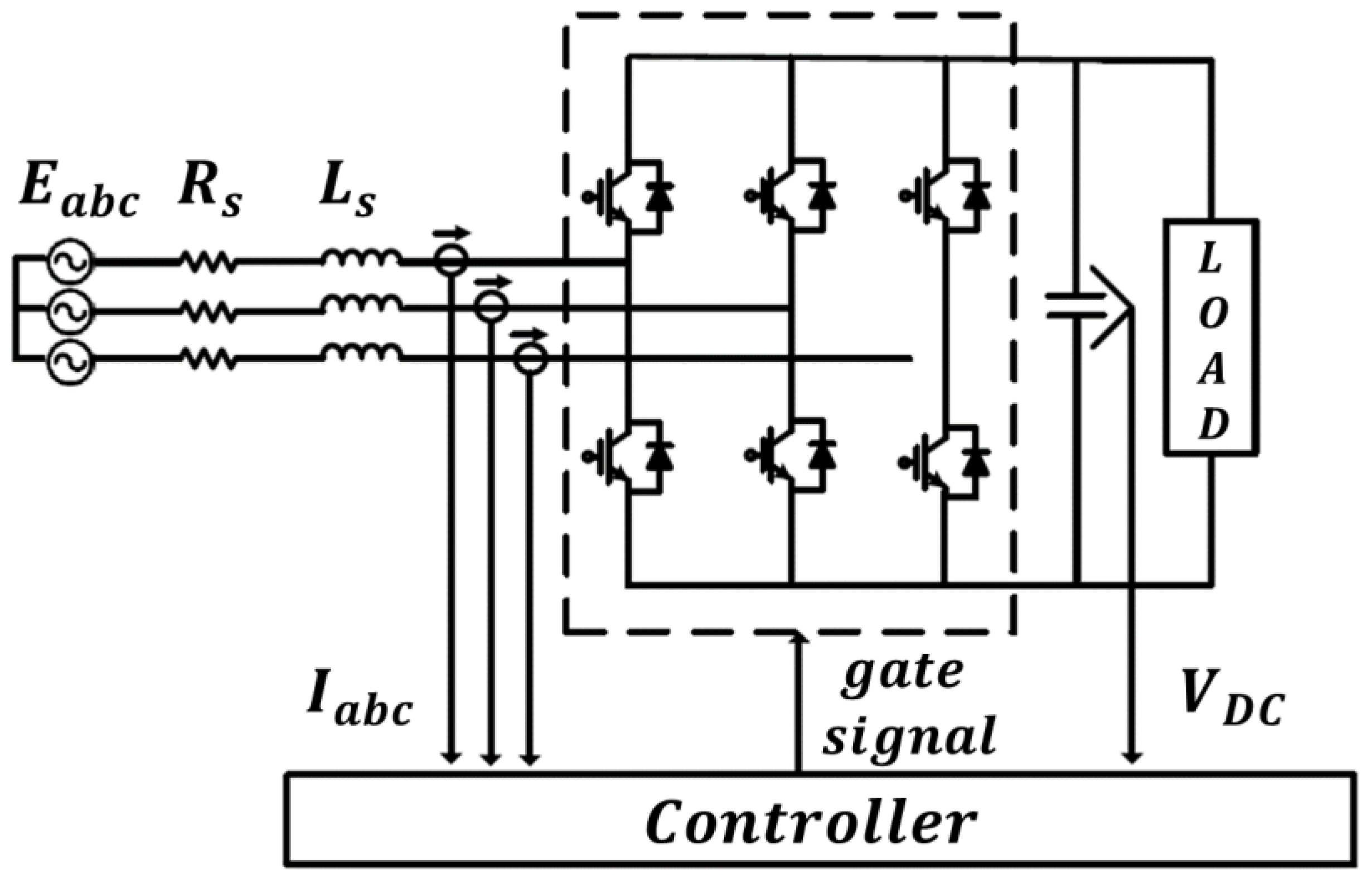
2. Conventional Sensorless Control for a Three-Phase PWM Converter
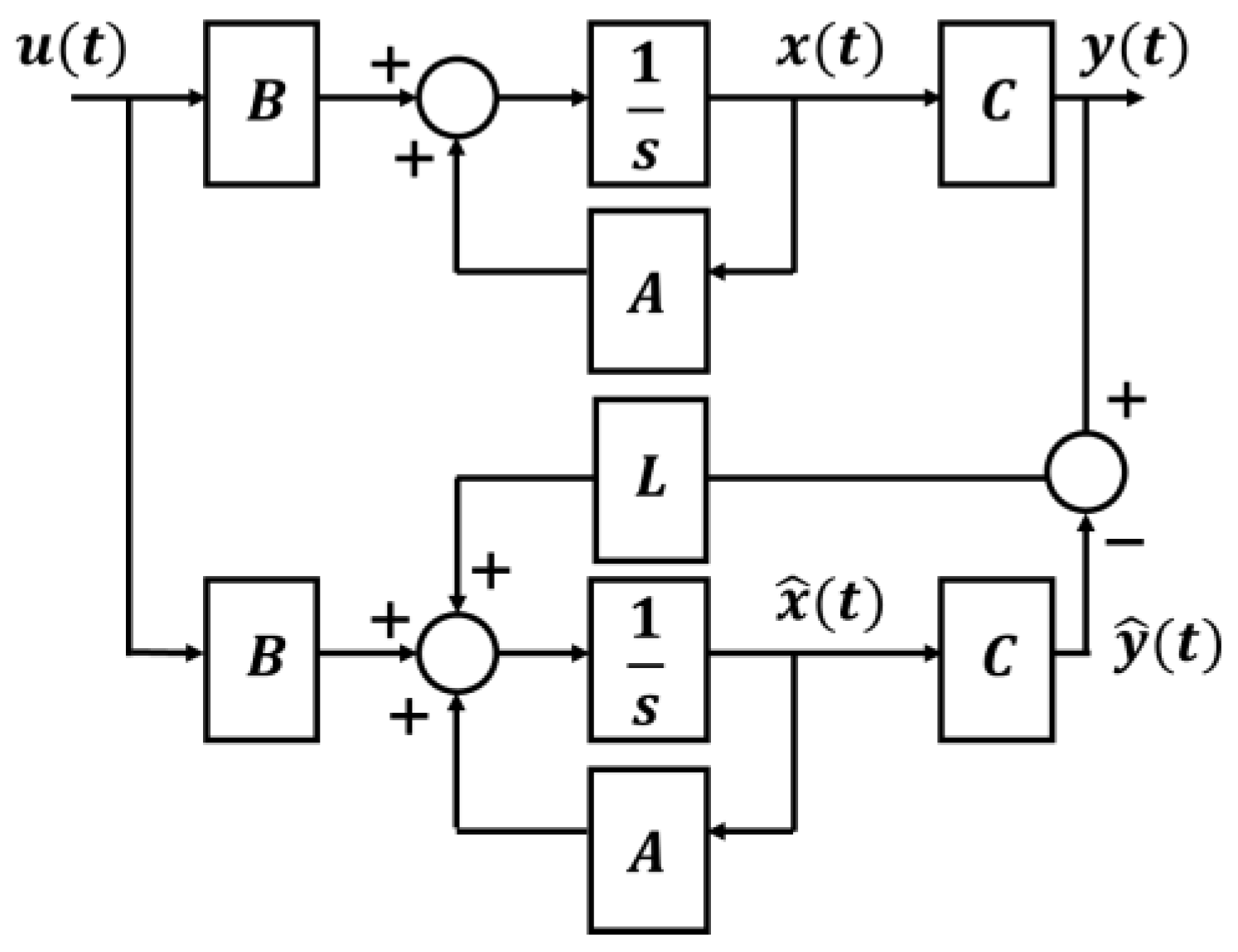
2.1. Source Voltage Observer
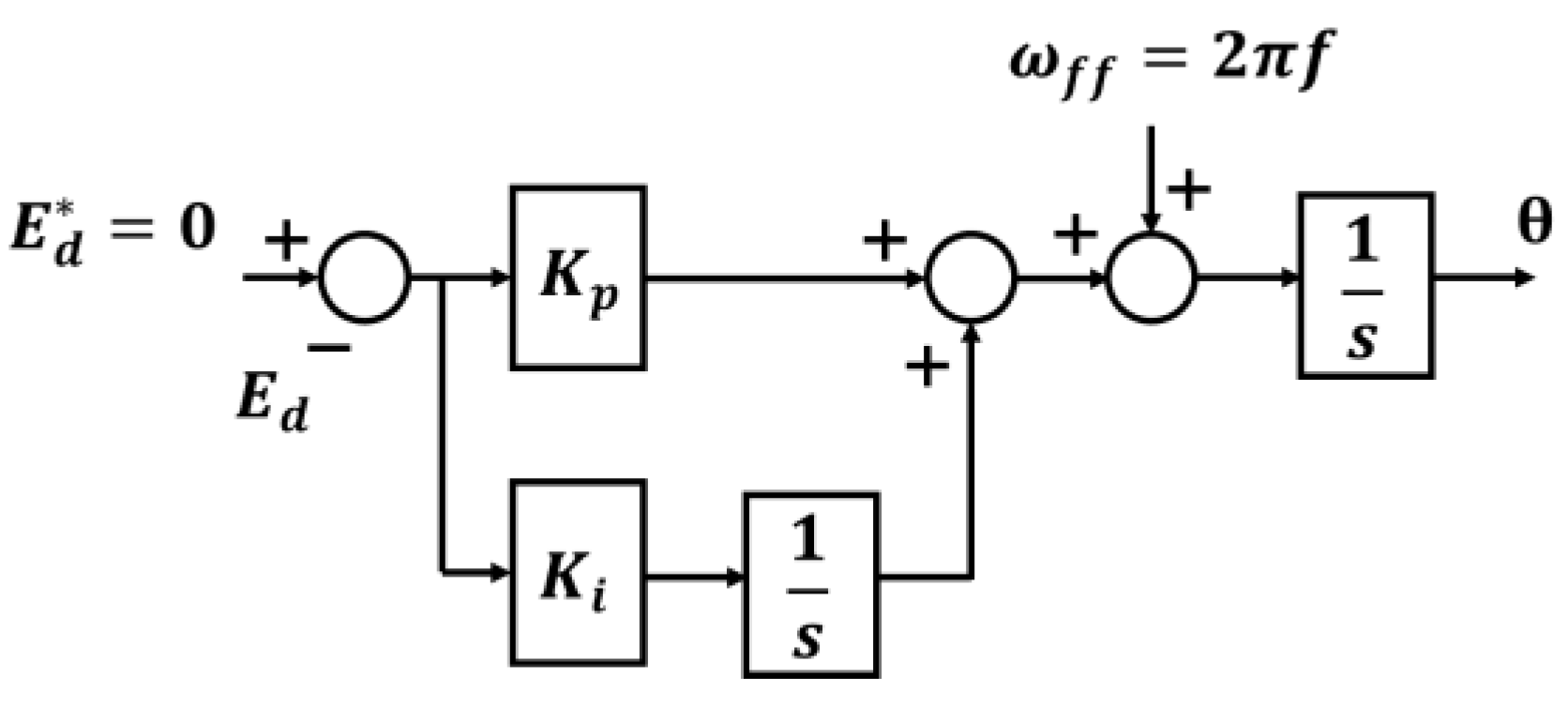
2.2. Grid Synchronization
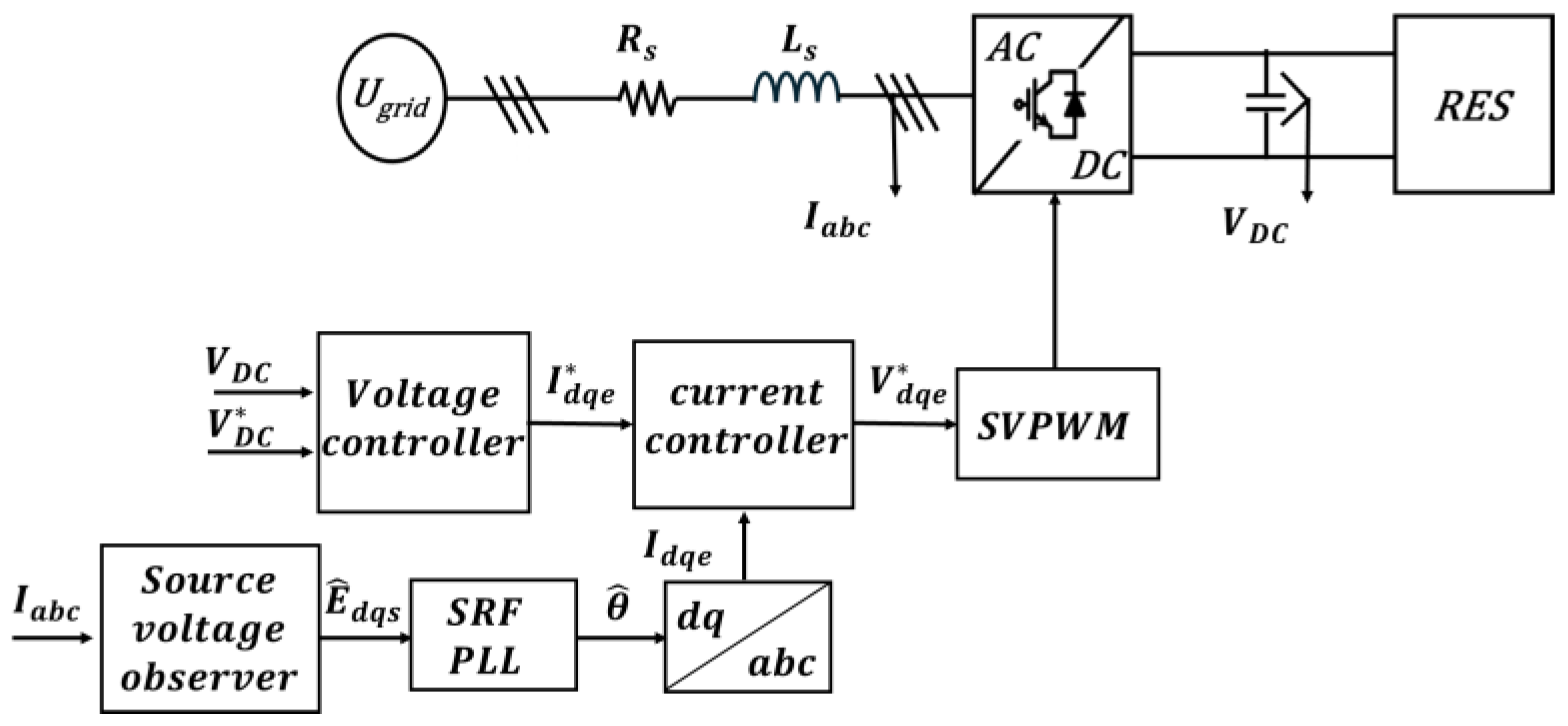
2.3. Grid Synchronization Sensorless Control for a Three-Phase PWM Converter
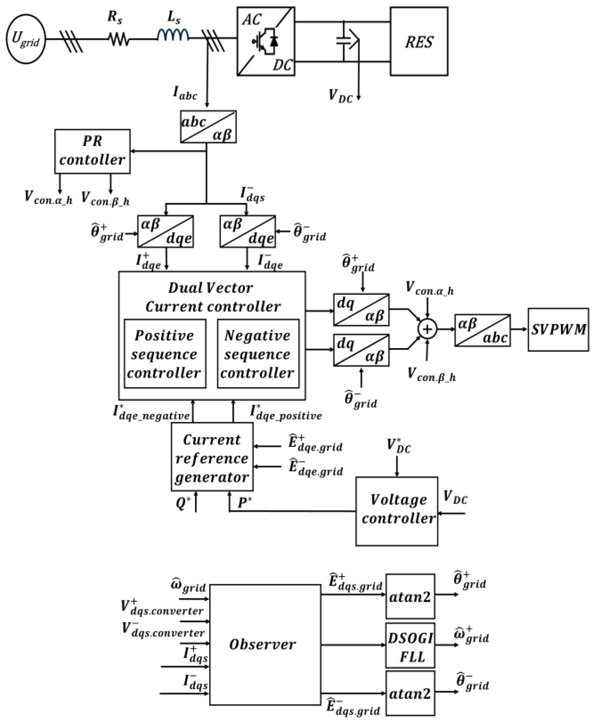
3. Proposed Sensorless Control of a Three-Phase PWM Converter Under Grid Disturbance Conditions
3.1. Source Voltage Observer for Proposed Sensorless Control of Three-Phase PWM Converter
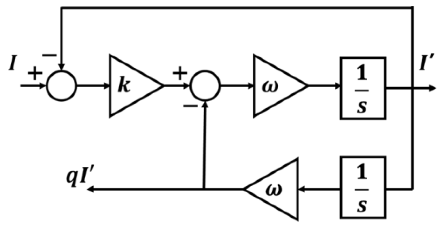
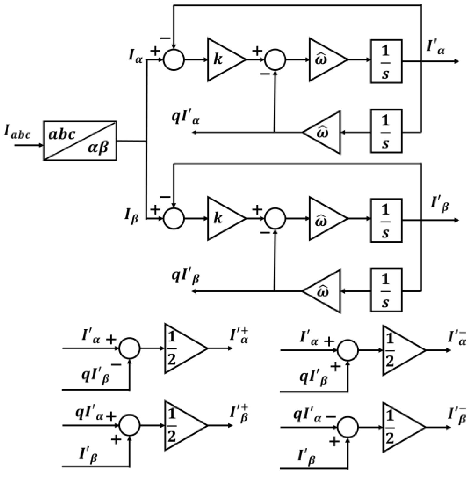
3.2. Separation of Positive and Negative Sequences Using DSOGI-QSG for the Proposed Sensorless Control of a Three-Phase PWM Converter
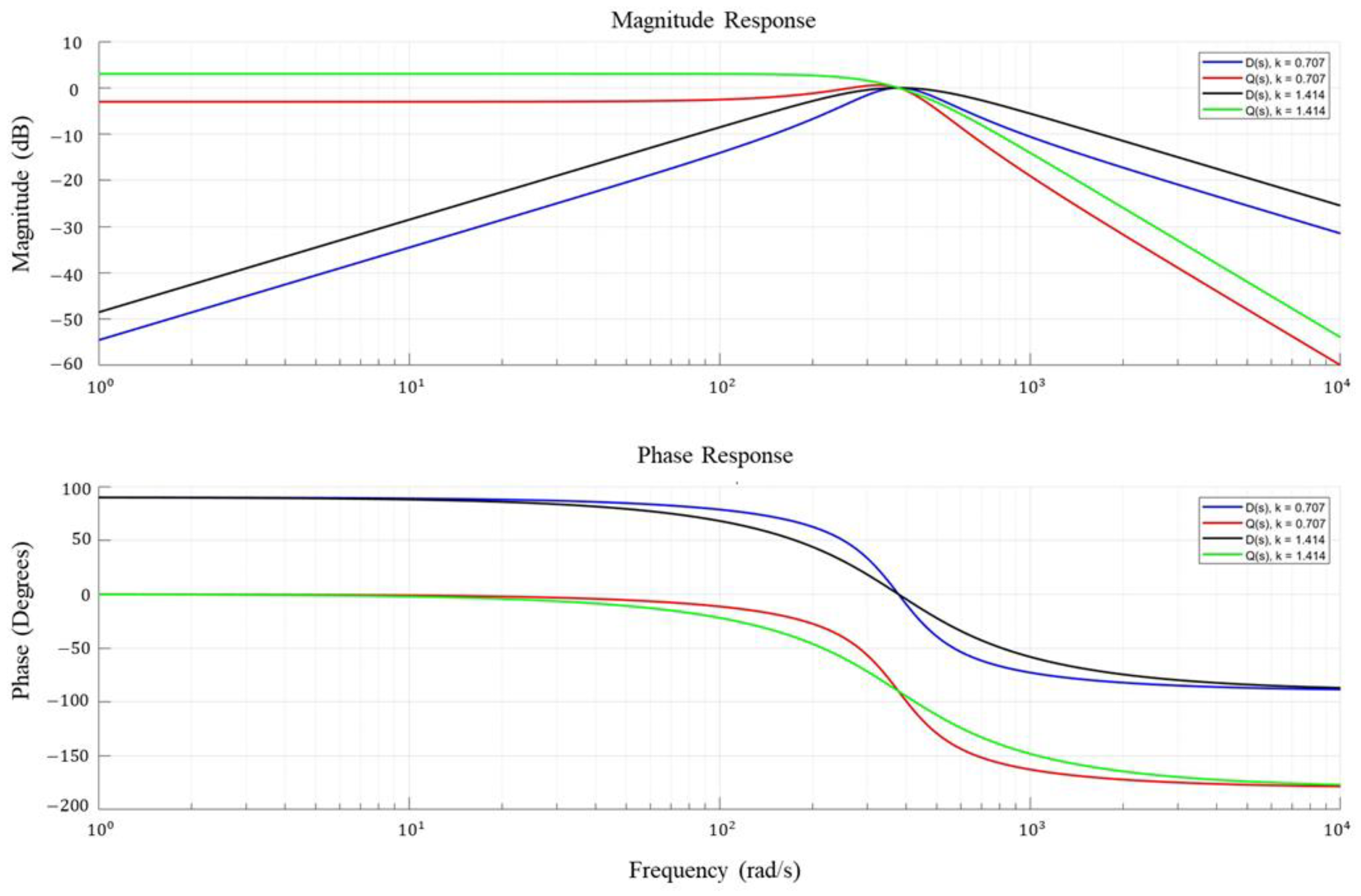
3.3. DSOGI-QSG-Based Frequency-Locked Loop for the Proposed Sensorless Control of a Three-Phase PWM Converter
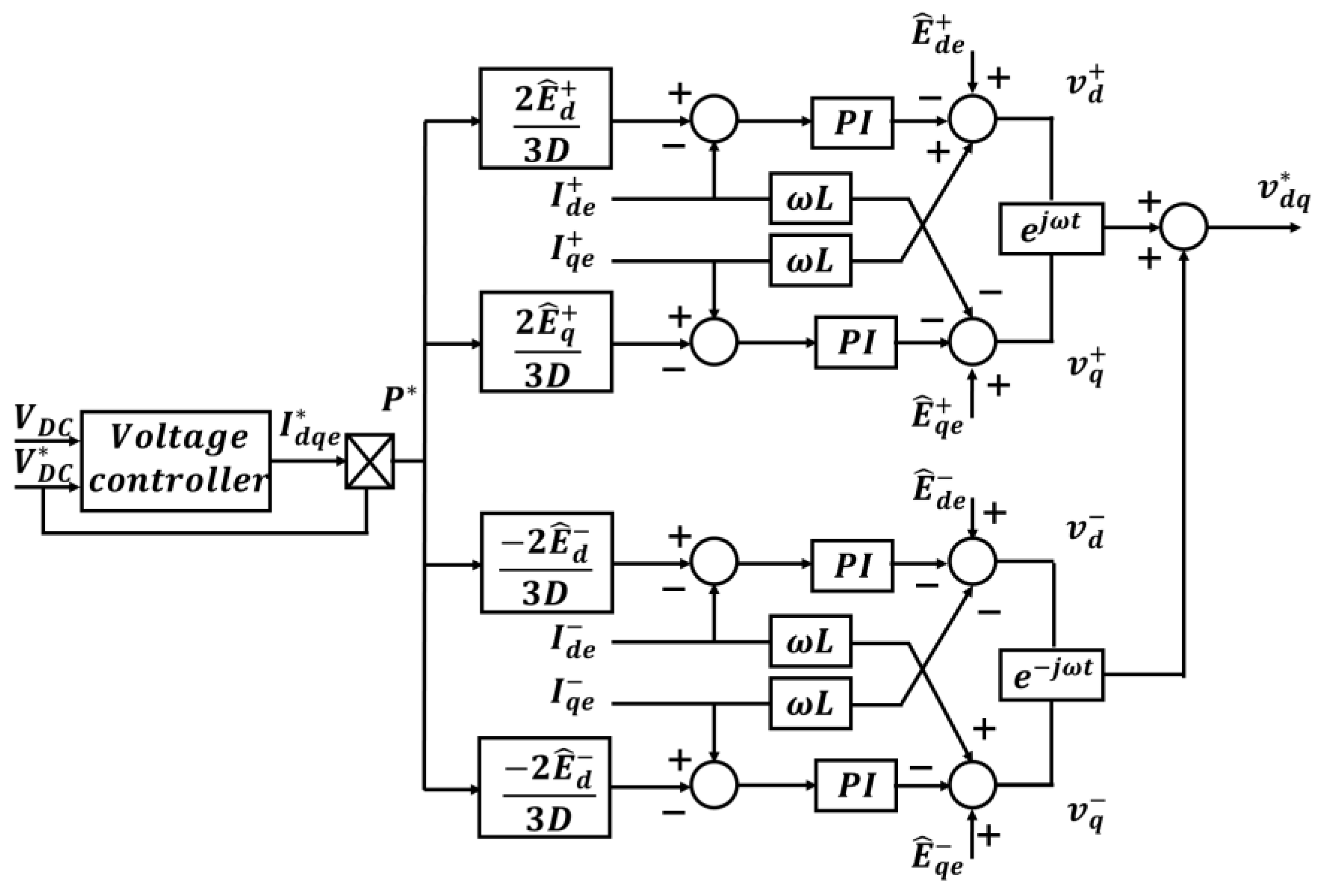
3.4. Current Control Strategy for a Three-Phase PWM Converter Under Grid Disturbance
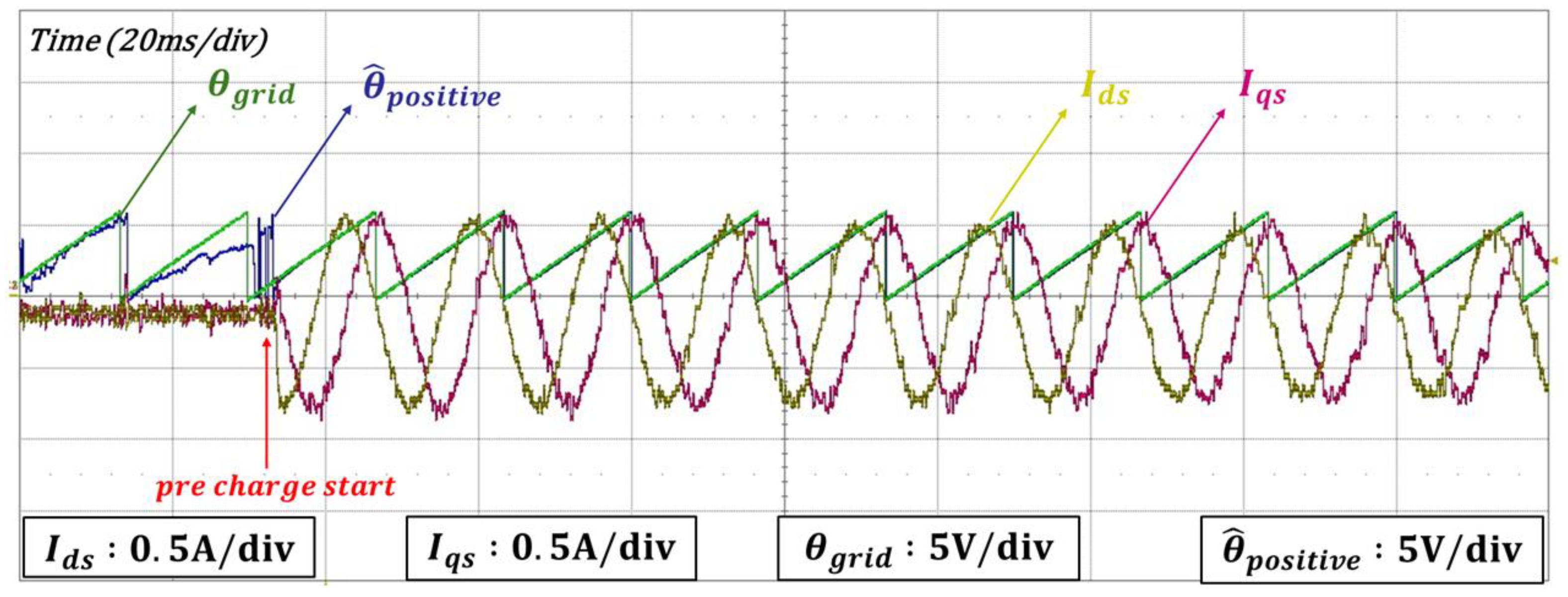
3.5. Grid Synchronization Strategy During Initial Operation
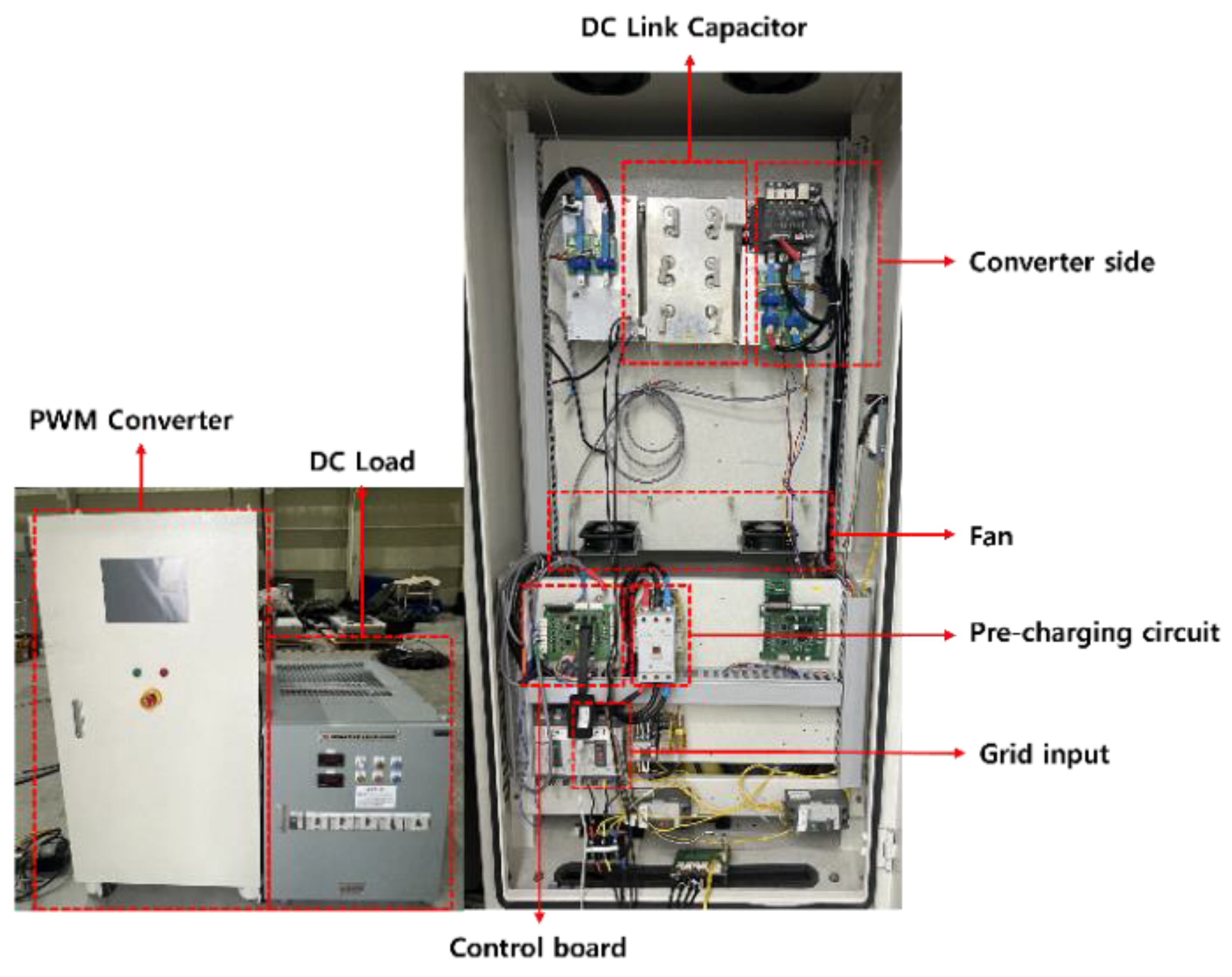
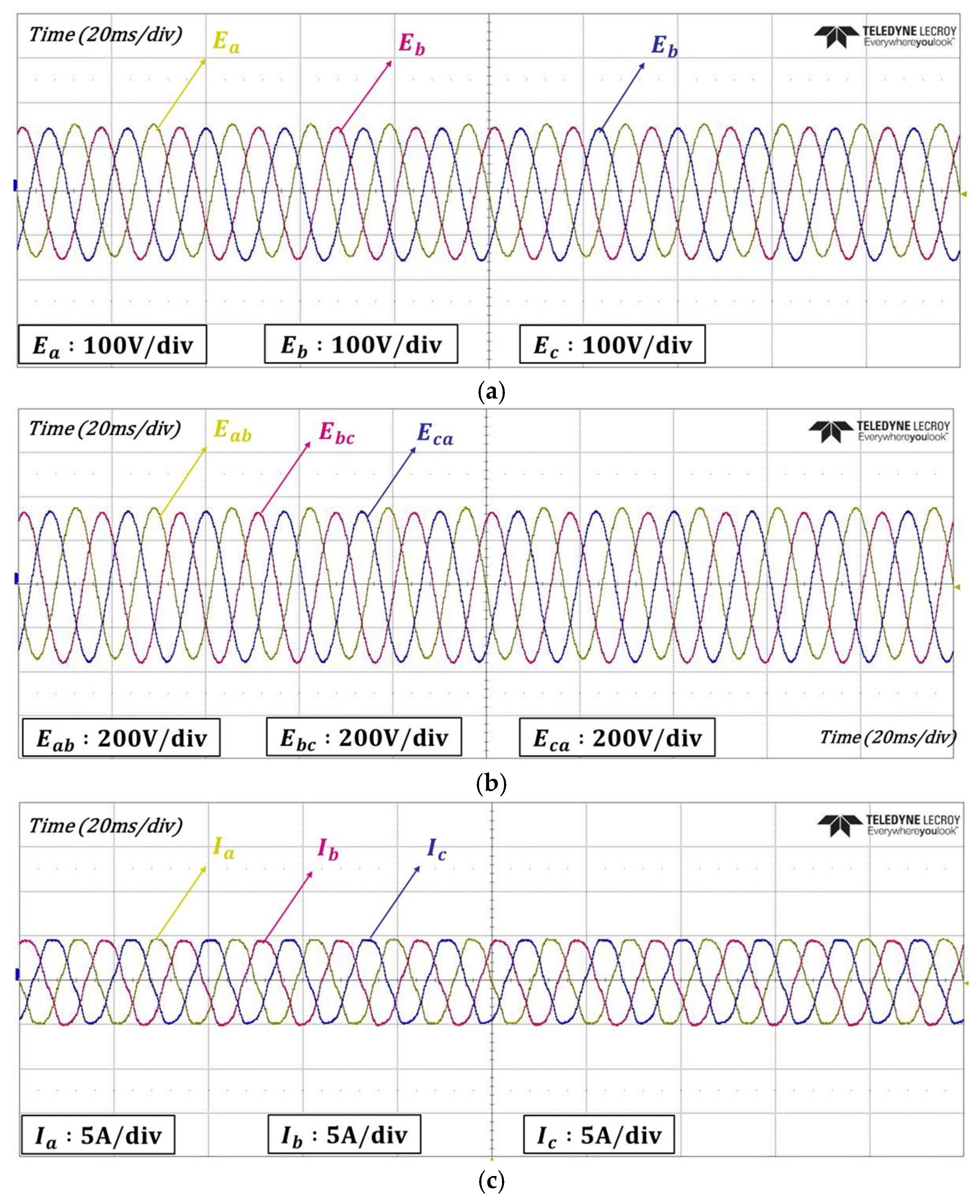
4. Experimental Results
5. Conclusions
Author Contributions
Funding
Data Availability Statement
Conflicts of Interest
References
- Chen, J.; Zhang, J.; Zhou, J.; Shi, G.; Jia, Y.; Wang, H.; Cai, X. An Enhanced Modular Multilevel Converter with Multiple MVAC Ports Based on Active Fundamental-Frequency Circulating Current Injection to Realize Full-Range Operation. IEEE Trans. Power Electron. 2024, 40, 5423–5439. [Google Scholar] [CrossRef]
- Zhang, J.; Li, H.; Kong, X.; Zhou, J.; Shi, G.; Zang, J.; Wang, J. A Novel Multiple-Medium-AC-Port Power Electronic Transformer. IEEE Trans. Ind. Electron. 2024, 71, 6568–6578. [Google Scholar] [CrossRef]
- Jung, E.; Kim, M.; Sul, S.K. Control scheme for source voltage sensorless PWM converters under source voltage unbalance. In Proceedings of the 2011 14th European Conference on Power Electronics and Applications, Birmingham, UK, 30 August–1 September 2011; pp. 1–10. [Google Scholar]
- Wu, R.; Dewan, S.; Slemon, G. Analysis of an AC-to-DC voltage source converter using PWM with phase and amplitude control. IEEE Trans. Ind. Appl. 1991, 27, 355–364. [Google Scholar] [CrossRef]
- Kaura, V.; Blasko, V. Operation of a voltage source converter at increased utility voltage. IEEE Trans. Power Electron. 1997, 12, 132–137. [Google Scholar] [CrossRef]
- Blasko, V.; Kaura, V. A new mathematical model and control of a three-phase AC-DC voltage source converter. IEEE Trans. Power Electron. 1997, 12, 116–123. [Google Scholar] [CrossRef]
- Ohnishi, T.; Fujii, K. Line voltage sensorless three phase PWM converter by tracking control of operating frequency. In Proceedings of the Power Convers. Conf.—PCC ’97, Nagaoka, Japan, 3–6 August 1997; Volume 1, pp. 247–252. [Google Scholar]
- Noguchi, T.; Tomiki, H.; Kondo, S.; Takahashi, I. Direct power control of PWM converter without power source voltage sensors. In Proceedings of the IAS ’96. Conference Record of the 1996 IEEE Industry Applications Conference Thirty-First IAS Annual Meeting, San Diego, CA, USA, 6–10 October 1996; Volume 2, pp. 941–946. [Google Scholar]
- Hansen, S.; Malinowski, M.; Blaabjerg, F.; Kazmierkowski, M.P. Sensorless control strategies for PWM rectifier. In Proceedings of the APEC 2000. Fifteenth Annual IEEE Applied Power Electronics Conference and Exposition (Cat. No.00CH37058), New Orleans, LA, USA, 6–10 February 2000; Volume 2, pp. 832–838. [Google Scholar]
- Song, H.S.; Joo, I.W.; Nam, K. Source voltage sensorless estimation scheme for PWM rectifiers under unbalanced conditions. IEEE Trans. Ind. Electron. 2003, 50, 1238–1245. [Google Scholar] [CrossRef]
- Yoo, H.; Kim, J.H.; Sul, S.K. Sensorless Operation of a PWM Rectifier for a Distributed Generation. IEEE Trans. Power Electron. 2007, 22, 1014–1018. [Google Scholar] [CrossRef]
- Ghodke, A.; Chatterjee, K. One-cycle-controlled bidirectional three-phase unity power factor ac–dc converter without having voltage sensors. IET Power Electron. 2012, 5, 1944–1955. [Google Scholar] [CrossRef]
- Ketzer, M.B.; Jacobina, C.B. Sensorless control technique for PWM rectifiers with voltage disturbance rejection and adaptive power factor. IEEE Trans. Ind. Electron. 2014, 62, 1140–1151. [Google Scholar] [CrossRef]
- Rahoui, A.; Bechouche, A.; Seddiki, H.; Abdeslam, D.O. Grid Voltages Estimation for Three-Phase PWM Rectifiers Control Without AC Voltage Sensors. IEEE Trans. Power Electron. 2017, 33, 859–875. [Google Scholar] [CrossRef]
- Lokesh, N.; Mishra, M.K.; Ismail, N.M. Variable Structure Control for Three Phase-Three Wire Nine Switch Converter with LCL Filter. In Proceedings of the 2019 IEEE 13th International Conference on Power Electronics and Drive Systems (PEDS), Toulouse, France, 9–12 July 2019. [Google Scholar]
- Wang, B.; Xu, Y.; Shen, Z.; Zou, J.; Li, C.; Liu, H. Current Control of Grid-Connected Inverter with LCL Filter Based on Extended-State Observer Estimations Using Single Sensor and Achieving Improved Robust Observation Dynamics. IEEE Trans. Ind. Electron. 2017, 64, 5428–5439. [Google Scholar] [CrossRef]
- Roslan, N.F.; Suul, J.A.; Rocabert, J.; Rodriguez, P. A comparative study of methods for estimating virtual flux at the point of common coupling in grid connected voltage source converters with LCL filter. In Proceedings of the 2016 IEEE Energy Conversion Congress and Exposition (ECCE), Milwaukee, WI, USA, 18–22 September 2016. [Google Scholar]
- Lai, N.B.; Baltas, G.N.; Marin, L.; Tarasso, A.; Rodriguez, P. Voltage Sensorless Control for Grid-connected Power Converters based on State Feedback and State Observer. In Proceedings of the 2020 IEEE 21st Workshop on Control and Modeling for Power Electronics (COMPEL), Aalborg, Denmark, 9–12 November 2020. [Google Scholar]
- Enjeti, P.N.; Choudhury, S.A. A new control strategy to improve the performance of a PWM AC to DC converter under unbalanced operating conditions. IEEE Trans. Power Electron. 1993, 8, 493–500. [Google Scholar] [CrossRef]
- Li, S.; Zhou, J.; Zhou, F.; Niu, F.; Deng, W. A Reduced Current Ripple Overmodulation Strategy for Indirect Matrix Converter. IEEE Trans. Ind. Electron. 2024, 72, 3768–3777. [Google Scholar] [CrossRef]
- Peng, L.; Fu, Z.; Xiao, T.; Qian, Y.; Zhao, W.; Zhang, C. An Improved Dual Second-Order Generalized Integrator Phased-Locked Loop Strategy for an Inverter of Flexible High-Voltage Direct Current Transmission Systems under Nonideal Grid Conditions. Processes 2023, 11, 2634. [Google Scholar] [CrossRef]
- Nazib, A.A.; Holmes, D.G.; McGrath, B.P. Decoupled DSOGI-PLL for Improved Three Phase Grid Synchronisation. In Proceedings of the 2018 International Power Electronics Conference (IPEC-Niigata 2018 -ECCE Asia), Niigata, Japan, 20–24 May 2018; pp. 3670–3677. [Google Scholar]
- Kang, J.-W.; Shin, K.-W.; Lee, H.; Kang, K.-M.; Kim, J.; Won, C.-Y. A Study on Stability Control of Grid Connected DC Distribution System Based on Second Order Generalized Integrator-Frequency Locked Loop (SOGI-FLL). Appl. Sci. 2018, 8, 1387. [Google Scholar] [CrossRef]
- Abdelrahem, M.; Hackl, C.M.; Kennel, R. Finite position set-phase locked loop for sensorless control of direct-driven permanent-magnet synchronous generators. IEEE Trans. Power Electron. 2017, 33, 3097–3105. [Google Scholar] [CrossRef]
- Ahmed, H.; Amamra, S.-A.; Bierhoff, M.H. Frequency-locked loop-based estimation of single-phase grid voltage parameters. IEEE Trans. Ind. Electron. 2018, 66, 8856–8859. [Google Scholar] [CrossRef]
- Wang, G.; Zhan, H.; Zhang, G.; Gui, X.; Xu, D. Adaptive compensation method of position estimation harmonic error for EMF-based observer in sensorless IPMSM drives. IEEE Trans. Power Electron. 2013, 29, 3055–3064. [Google Scholar] [CrossRef]
- Xu, W.; Jiang, Y.; Mu, C.; Blaabjerg, F. Improved nonlinear flux observer-based second-order SOIFO for PMSM sensorless control. IEEE Trans. Power Electron. 2018, 34, 565–579. [Google Scholar] [CrossRef]
- Sreejith, R.; Singh, B. Sensorless Predictive Current Control of PMSM EV Drive Using DSOGI-FLL Based Sliding Mode Observer. IEEE Trans. Ind. Electron. 2020, 68, 5537–5547. [Google Scholar] [CrossRef]
- Kivanc, O.C.; Ozturk, S.B. Sensorless PMSM drive based on stator feedforward voltage estimation improved with MRAS multiparameter estimation. IEEE/ASME Trans. Mechatron. 2018, 23, 1326–1337. [Google Scholar] [CrossRef]
- Pinto, J.; Carvalho, A.; Rocha, A.; Araújo, A. Comparison of DSOGI-Based PLL for Phase Estimation in Three-Phase Weak Grids. Electricity 2021, 2, 244–270. [Google Scholar] [CrossRef]
- Fuad, K. Grid-Voltage Synchronization Algorithms Based on Phase-Locked Loop and Frequency-Locked Loop for Power Converters. Master’s Thesis, Aalto University, Espoo, Finland, 2014. [Google Scholar]
- Jang, J. Sensorless Control of PMSMs for Wide Speed Operation Range. Ph.D. Dissertation, Seoul National University, Seoul, Republic of Korea, 2006. [Google Scholar]
- Setiawan, I.; Facta, M.; Priyadi, A.; Purnomo, M.H. Comparison of three popular PLL schemes under balanced and unbalanced grid voltage conditions. In Proceedings of the 2016 8th International Conference on Information Technology and Electrical Engineering (ICITEE), Yogyakarta, Indonesia, 5–6 October 2016. [Google Scholar]
- Priyanka, B.; V, S.K.; Lavanya, M.C.; Krishnan V, M. Phase-Locked Loop (PLL) Techniques for Grid Synchronization: A Comprehensive Review. In Proceedings of the 2024 Second International Conference on Emerging Trends in Information Technology and Engineering (ICETITE), Vellore, India, 22–23 February 2024. [Google Scholar]
- Rodríguez, P.; Luna, A.; Muñoz-Aguilar, R.S.; Etxeberria-Otadui, I.; Teodorescu, R.; Blaabjerg, F. A Stationary Reference Frame Grid Synchronization System for Three-Phase Grid-Connected Power Converters Under Adverse Grid Conditions. IEEE Trans. Power Electron. 2011, 27, 99–112. [Google Scholar] [CrossRef]
- Kim, H.-S.; Kim, K.-H. Voltage-Sensorless Control Scheme for a Grid Connected Inverter Using Disturbance Observer. Energies 2017, 10, 166. [Google Scholar] [CrossRef]
- Qiming, C.; Fengren, T.; Jie, G.; Yu, Z.; Deqing, Y. The separation of positive and negative sequence component based on SOGI and cascade DSC and its application at unbalanced PWM rectifier. In Proceedings of the 2017 29th Chinese Control and Decision Conference (CCDC), Chongqing, China, 28–30 May 2017. [Google Scholar]
- Rodríguez, P.; Luna, A.; Candela, I.; Mujal, R.; Teodorescu, R.; Blaabjerg, F. Multiresonant frequency-locked loop for grid synchronization of power converters under distorted grid conditions. IEEE Trans. Ind. Electron. 2011, 58, 127–138. [Google Scholar] [CrossRef]
- Rioual, P.; Pouliquen, H.; Louis, J.P. Regulation of a PWM rectifier in the unbalanced network state using a generalized model. IEEE Trans. Power Electron. 1996, 11, 495–502. [Google Scholar] [CrossRef]
- Song, H.-S.; Nam, K. Dual current control scheme for PWM converter under unbalanced input voltage conditions. IEEE Trans. Ind. Electron. 1999, 46, 953–959. [Google Scholar] [CrossRef]
- Park, H.-S.; Heo, H.-J.; Choi, B.-S.; Kim, K.C.; Kim, J.-M. Speed Control for Turbine-Generator of ORC Power Generation System and Experimental Implementation. Energies 2019, 12, 200. [Google Scholar] [CrossRef]
- Regatron, Technical Datasheets, TC.ACS.50.528.4WR.S.LC. Programmable Regenerative AC Power Supply. Available online: https://www.regatron.com/product/overview/programmable-bidirectional-ac-power-sources/tc-acs-series/#technical-datasheets (accessed on 1 March 2025).
- BS EN 50160:2022; Voltage Characteristics of Electricity Supplied by Public Electricity Networks. European Standards: Brussels, Luxembourg, 2022.


| Specification | Value |
|---|---|
| Rated Grid Voltage | 220 Vrms/60 Hz |
| DC Link Voltage | 350 V |
| Interface Inductor | 2 mH |
| DC Link Capacitor | 4700 μF |
| Switching Frequency | 5 kHz |
| Rated Power | 10 kW |
| No. | Test Condition |
|---|---|
| 1 | Balanced grid condition |
| 2 | Unbalanced grid condition |
| 3 | Harmonic injection |
| 4 | Frequency step change |
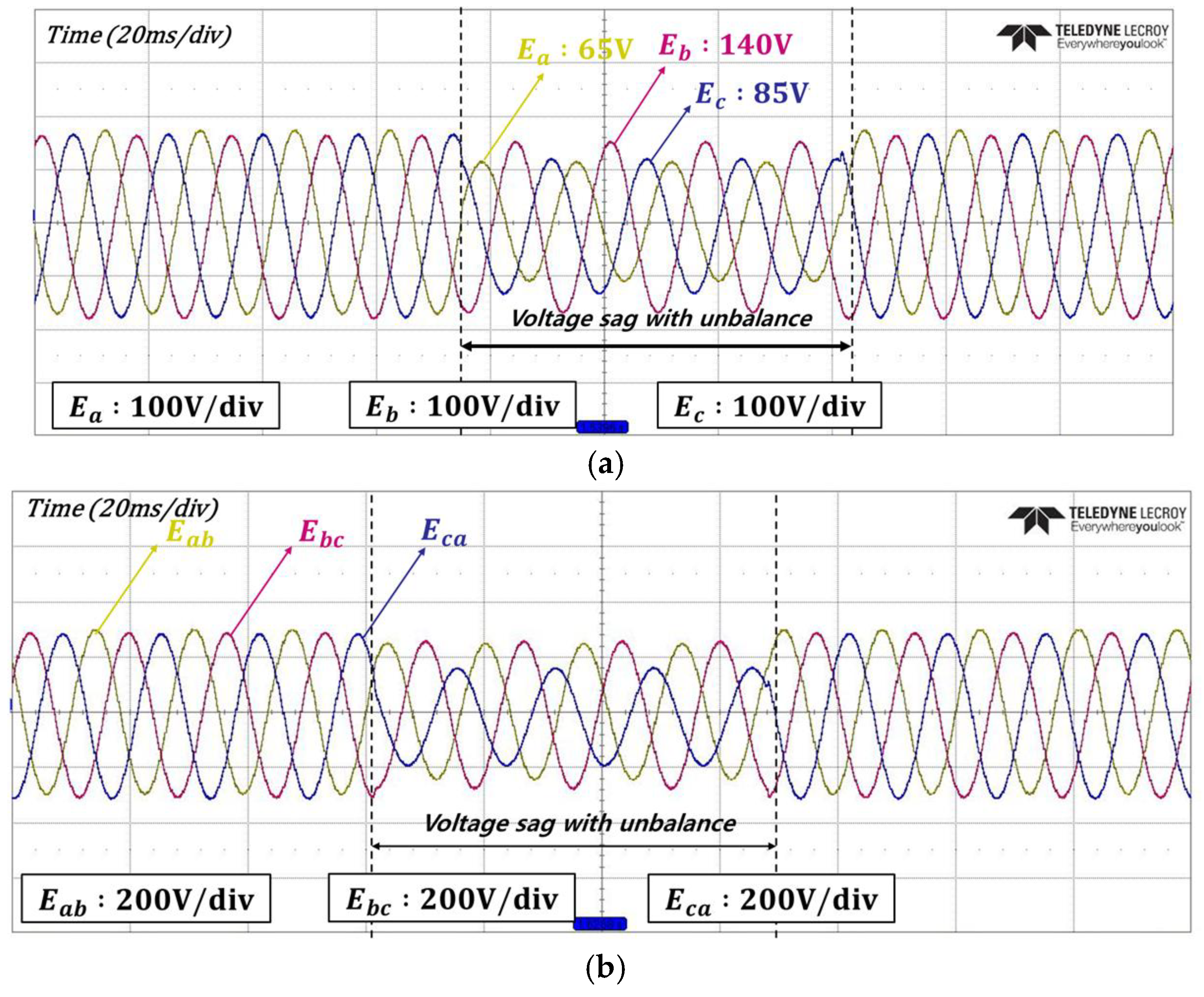
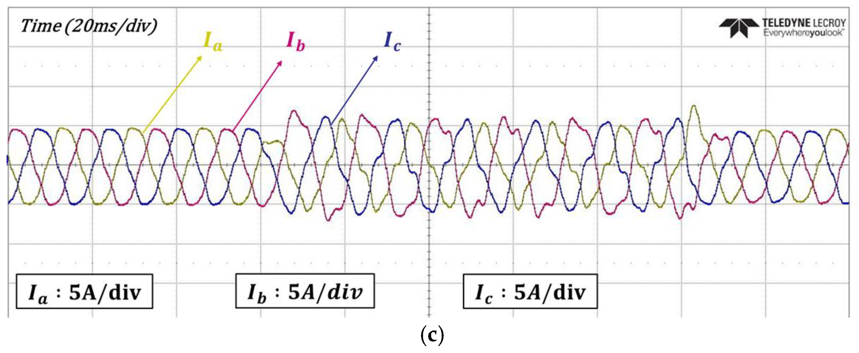
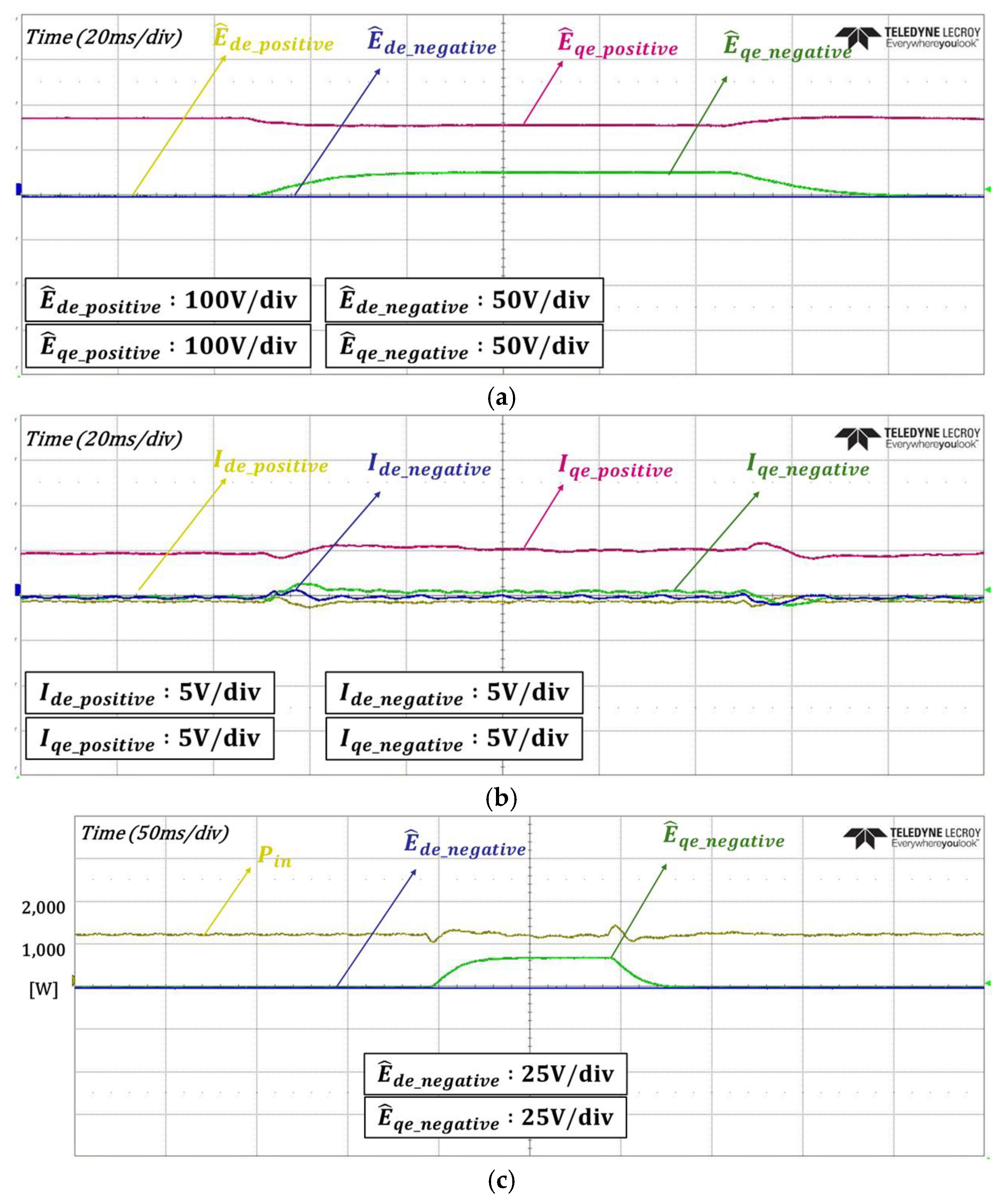
| 5 | Voltage sag with unbalance |
Disclaimer/Publisher’s Note: The statements, opinions and data contained in all publications are solely those of the individual author(s) and contributor(s) and not of MDPI and/or the editor(s). MDPI and/or the editor(s) disclaim responsibility for any injury to people or property resulting from any ideas, methods, instructions or products referred to in the content. |
© 2025 by the authors. Licensee MDPI, Basel, Switzerland. This article is an open access article distributed under the terms and conditions of the Creative Commons Attribution (CC BY) license (https://creativecommons.org/licenses/by/4.0/).
Share and Cite
Kang, S.-P.; Kim, D.-Y.; Kim, J.-M. Enhanced Voltage Sensorless Control for a PWM Converter with DSOGI-FLL Under Grid Disturbances. Energies 2025, 18, 2199. https://doi.org/10.3390/en18092199
Kang S-P, Kim D-Y, Kim J-M. Enhanced Voltage Sensorless Control for a PWM Converter with DSOGI-FLL Under Grid Disturbances. Energies. 2025; 18(9):2199. https://doi.org/10.3390/en18092199
Chicago/Turabian StyleKang, Seung-Pyo, Dong-Youn Kim, and Jang-Mok Kim. 2025. "Enhanced Voltage Sensorless Control for a PWM Converter with DSOGI-FLL Under Grid Disturbances" Energies 18, no. 9: 2199. https://doi.org/10.3390/en18092199
APA StyleKang, S.-P., Kim, D.-Y., & Kim, J.-M. (2025). Enhanced Voltage Sensorless Control for a PWM Converter with DSOGI-FLL Under Grid Disturbances. Energies, 18(9), 2199. https://doi.org/10.3390/en18092199