1. Introduction
With the increasing penetration of renewable energy in power grids, the reduction in fossil fuel usage has mitigated environmental pollution. However, the growing share of renewables has introduced challenges such as randomness, volatility, and intermittency [
1,
2], increasing the complexity of grid operation and potentially affecting system security and stability. As key flexibility resources, energy storage systems (ESSs) can effectively mitigate power fluctuations through their charge and discharge characteristics, enhance renewable energy accommodation, and fundamentally alleviate the integration issues caused by high renewable penetration [
3].
Hybrid energy storage systems (HESSs) integrate multiple storage technologies to leverage the advantages of different energy storage types [
4,
5]. For instance, short-duration high-power storage is suitable for rapid load fluctuation responses, while long-duration storage can balance the intermittent power supply from renewables. This coordinated optimization approach significantly enhances system flexibility and economic efficiency, making it an effective strategy for addressing large-scale renewable energy integration.
Given the challenges caused by insufficient grid flexibility under high-renewable scenarios, the planning and optimization of hybrid energy storage systems have become crucial directions in power system development. The further promotion and advancement of hybrid storage technology will help overcome existing cost barriers and provide more economical and flexible solutions for renewable energy integration and grid operation.
Several studies have explored various flexibility resources in power systems. Authors [
6] proposed a nonlinear planning model considering wind and solar energy accommodation through flexibility retrofits. The results demonstrated that reasonable flexibility retrofits of thermal power units could further reduce overall costs and alleviate wind and solar curtailment. Moreover, it was found that appropriate subsidies for wind and solar power could incentivize enterprises to retrofit thermal power units, indirectly increasing renewable energy accommodation. A study [
7] introduced an integrated planning and scheduling method for source–grid–load–storage (SGLS) power systems, incorporating multiple energy storage types. The study showed that the performance of the integrated SGLS method in utilizing system flexibility resources depends on the capacity and power configuration of different storage types.
Additionally, demand response (DR) has become a major dispatchable resource on the load side [
8,
9]. Authors [
10] conducted a coordinated planning study integrating two demand response mechanisms—shiftable loads and interruptible loads—with wind farms. However, the study only considered a single type of flexibility resource, neglecting the complementary characteristics of multiple flexibility resources, which led to suboptimal utilization. Other authors [
11] considered multiple flexibility resources, including thermal power retrofits, demand response, and energy storage stations, and developed an optimal investment cost model for high-renewable-energy power planning. Researchers [
12] further accounted for the spatial distribution of flexible resources while optimizing the capacity selection of multiple flexibility resources in power systems. Reference [
13] proposes a joint planning model considering the operational characteristics of renewable energy, storage systems, the power grid, and conventional units. References [
14,
15] focus on the co-planning of wind power and storage, considering different scenarios affecting wind-storage coordination. However, only a limited number of studies have fully covered integrated planning across renewable energy, storage, transmission networks, and demand-side flexibility resources [
16]. Authors [
16] studied the source–grid–load–storage problem, modeling demand-side response through direct load control (DLC) while incorporating an energy storage model. However, the study did not account for the impact of large-scale transmission lines in the planning process.
As a primary flexibility resource, energy storage can optimize the integration of renewable energy and improve its efficient utilization [
17,
18]. However, the high cost of storage remains a significant barrier to investment in energy storage facilities. With the continuous development and application of hybrid storage technology, the combination of multiple storage types offers an effective approach to enhancing power system flexibility and economic efficiency. By integrating different storage resources, hybrid energy storage systems can better adapt to variations in electricity demand and balance the volatility and intermittency of renewable energy [
19,
20]. This configuration approach fully leverages the advantages of various storage technologies, optimizes resource allocation, and enhances the overall economic efficiency of the system.
Recent advancements in energy-efficient technologies, such as those demonstrated by Citroni et al. [
21] in their comprehensive review of ultra-low-power integration and energy harvesting for self-sufficient devices, further highlight the critical role of optimized energy management systems. Building on these foundational insights, our study extends this discourse to hybrid energy storage systems (HESSs) in high-penetration renewable grids, addressing the unique challenges of large-scale flexibility and economic viability.
The current challenges in hybrid energy storage planning include identifying the specific storage needs of power systems, optimally configuring different storage types, and establishing economically viable mechanisms to support the sustainable development of hybrid energy storage systems. Hybrid energy storage systems (HESSs) combine the characteristics of power-type and energy-type storage devices to simultaneously meet the grid’s requirements for fast-response and long-duration energy storage. Power-type storage (e.g., supercapacitors) effectively mitigates second-level fluctuations from renewable sources, while energy-type storage (e.g., lithium batteries) is suitable for hourly level energy dispatch. This coordinated configuration can enhance renewable energy utilization while potentially reducing the overall costs of storage systems under optimal operating conditions.
Therefore, this study selected a high-renewable penetration region as the case study background and optimized the siting and configuration of hybrid storage systems within the main grid framework. A hybrid energy storage optimization model was developed for high-renewable-penetration scenarios to determine the optimal storage capacity required to ensure economic efficiency in high-renewable power grids.
Hybrid energy storage systems (HESSs) synergistically combine power-intensive and energy-dense technologies to optimally manage renewable energy variability. This integrated approach provides comprehensive grid support, outperforming single-technology solutions in both operational flexibility and system economics for renewable-rich power networks. The organization of this paper is as follows:
Section 2 presents the modeling of the hybrid energy storage system.
Section 3 provides case studies and simulation analysis.
Section 4 discusses the sensitivity of the key influencing factors and concludes this paper. To assist readers in understanding the technical terminology used throughout the paper, key terms are summarized in Abbreviation section, providing a glossary of technical terms and abbreviations at the end of this manuscript.
2. Hybrid Energy Storage Configuration Demand Calculation Model Under High Renewable Penetration
In new power systems, the flexibility demand is significantly affected by the volatility of the renewable energy output. The response characteristics of various flexibility resources on the source, load, and storage sides differ considerably, leading to a more complex interactive response structure. The lack of flexible resources, coupled with the increasing penetration of renewable energy, has intensified the pressure on renewable energy accommodation.
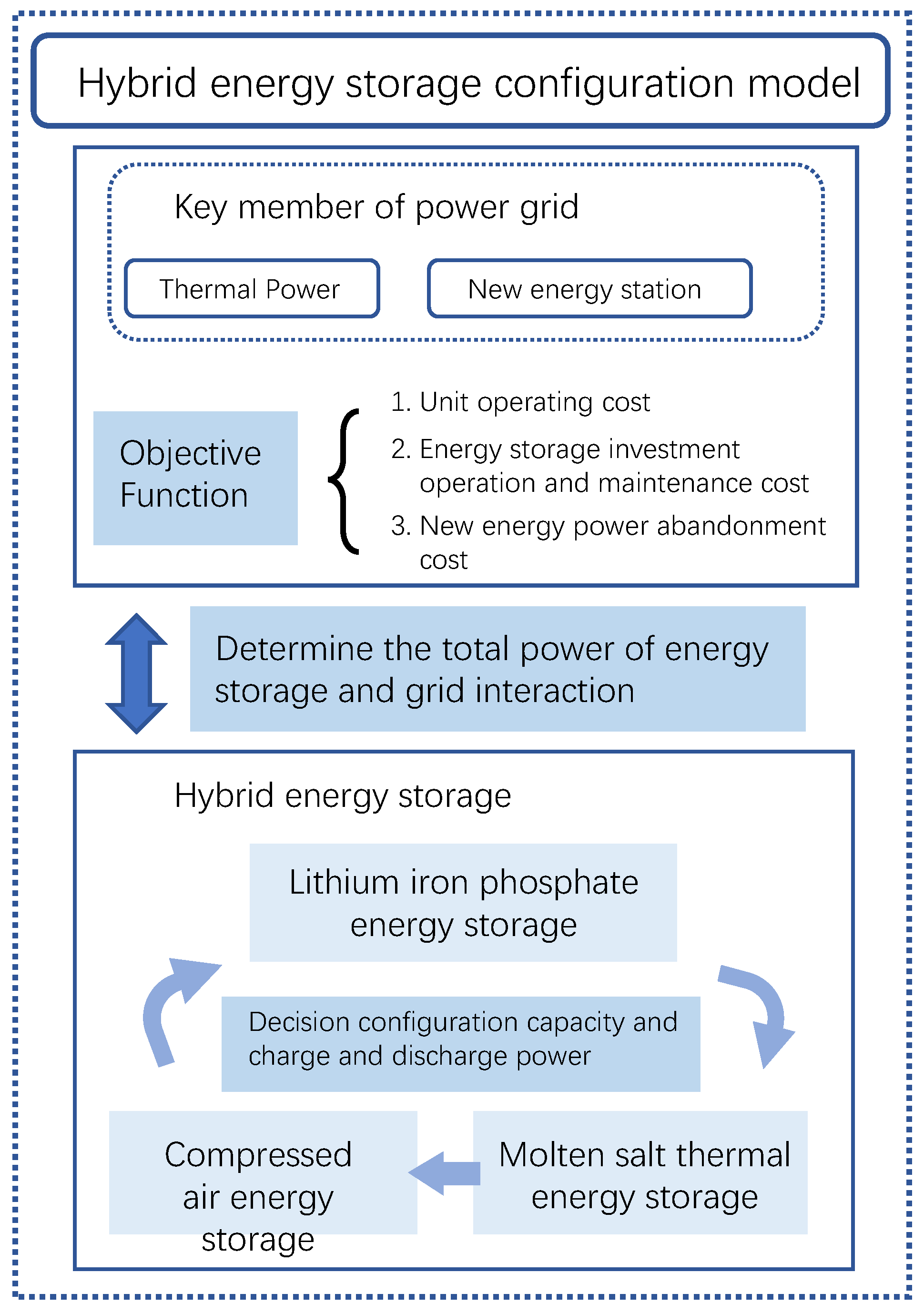
This study developed a hybrid energy storage configuration demand calculation model tailored for high-renewable-penetration systems, based on the supply–demand balance of system flexibility. The model comprehensively considers factors such as thermal unit startup and shutdown operations, renewable energy accommodation, energy storage station configuration, storage system operation, and system capacity reserves. By jointly optimizing the siting and investment scale of energy storage, the model determines the optimal deployment of storage facilities. The configuration framework of the proposed model is illustrated in
Figure 1.
2.1. Objective Function
Taking the power grid system as the main entity, the objective cost includes unit startup and operation costs, energy storage investment, operation and capacity degradation costs, and renewable energy curtailment losses. The model is established with the objective of minimizing the overall operational cost of the power grid:
where
is the planning scenario;
is the probability of scenario s;
is the probability of scenario s;
and
are, respectively, the startup and shutdown costs of conventional thermal power units in scenario
;
is the investment, operation, and maintenance cost of energy storage stations;
is the operational cost of conventional thermal power units in scenario
;
is the capacity degradation cost during energy storage operation in scenario
;
is the curtailment cost of renewable energy in scenario
.
The calculation of each cost item in the objective function is as follows:
- (1)
Startup and shutdown costs of thermal units
The startup cost function and shutdown cost function of thermal units are given as follows:
where
represents the status of unit i at time period t, where
indicates startup and
indicates shutdown.
and
denote the startup and shutdown costs of unit iii, respectively.
- (2)
Operating cost of the unit
where
represents the power output of the
g conventional generator in scenario s at time period t;
denotes the unit fuel cost required for power generation using conventional thermal generators;
represents the environmental cost associated with pollutant emissions from conventional generators during operation; and
T denotes the total number of time periods.
- (3)
Investment and operation and maintenance costs for energy storage
where
represents the index of the storage device to be constructed;
denotes the set of storage devices to be constructed;
represents the configured capacity of storage device
h;
denotes the unit capacity investment cost of the storage system;
represents the annualization factor of the storage investment; and
represents the unit capacity operation and maintenance cost of the storage device.
- (4)
Cost of energy storage capacity loss
where
represents the discharge power of storage device h at time period t under scenario s;
denotes the capacity degradation coefficient of the storage system; Δ
t represents the unit time interval, which was set to 1 h in this study.
- (5)
The cost of abandoned electricity from new energy sources
where
represents the set of renewable energy units;
denotes the unit curtailment cost;
represents the predicted output of renewable energy unit
f at time period
t under scenario
s;
represents the actual output of renewable energy unit
f at time period
t under scenario
s.
2.2. Constraints
- (1)
Power supply–demand balance constraint
where
represents the charging power of storage device
h at time
t;
represents the discharging power of storage device
h at time
t;
denotes the active load at time
t.
- (2)
Branch current flow constraints
The line power is calculated by using the DC power flow model.
where
represents the power injected at each node;
is the m × m branch reactance matrix, with m representing the number of branches;
is the n × n node reactance matrix, with n representing the number of nodes;
is the n × m node-branch incidence matrix;
is the power distribution factor, which characterizes the relationship between branch power and node injection power.
where
represents the influence matrix that shows the effect of other branches on the power flow when the power flow in one transmission line increases by one unit.
where
is the maximum allowed flow on branch l;
is the node-to-branch transfer distribution factor from node n to branch l, obtained from the system’s configuration;
is the node-to-branch transfer distribution factor from branch k to branch l, obtained from the system’s configuration.
- (3)
Constraints on the start-up and shutdown of conventional units
- (4)
Conventional unit operation constraints
- a.
Unit output constraint
where
is the minimum output of conventional generator g;
is the maximum output of conventional generator
g.
- b.
Unit climbing constraint
where
is the maximum allowed downward ramp rate for generator g;
is the maximum allowed upward ramp rate for generator g.
- (5)
New energy operation constraints
- a.
New energy output constraints
where
is the upper output limit of renewable generator
f;
is the lower output limit of renewable generator
f.
- b.
New energy utilization minimum threshold constraints
where
is the maximum generation capacity of renewable generator
f at time period
t;
is the probability of scenario s;
is the minimum threshold for renewable energy utilization.
- (6)
Constraints on energy storage operation
The energy storage operation constraints mainly include the state of charge (SOC) constraint, the charging and discharging power limit constraint, and the charging and discharging state constraint.
where
is the capacity degradation of storage device h at time period
t;
is the remaining stored energy in battery
h at time period
t;
and
are the lower and upper limits of the state of charge (SOC) of the storage device, respectively;
and
are the charging and discharging efficiency coefficients of the storage device.
- b.
Constraints on charging and discharging energy storage
where
and
are the charging and discharging states of storage device
h at time period
t, represented as binary variables. A value of 1 indicates the corresponding state, while 0 indicates the absence of the corresponding state.
- c.
Energy storage location constraint
where
is the configuration status of storage device h, represented as a binary variable. A value of 1 indicates the storage device is configured, and 0 indicates it is not configured.
and
represent the maximum capacity and configuration power of storage device h at time period t, which can be set to large values.
The optimization model was formulated as a mixed-integer linear programming (MILP) problem. It was implemented using the YALMIP modeling environment and solved with the solver CPLEX 12.6.
3. Case Study Analysis
3.1. Comparative Analysis of Hybrid Energy Storage and Single Energy Storage Configuration Strategy
The case study is based on the typical grid structure of major power networks in northwest China, which includes 44,000 MW of wind power, 45,000 MW of photovoltaic power, and 63,000 MW of thermal power units, resulting in a renewable energy penetration rate of 58.6%. The simulation adopted a 1 h temporal resolution, with wind and PV generation profiles derived from typical daily patterns clustered from annual historical data. The simulation aimed to optimize the full-cycle flexibility cost of a high-renewable-penetration system while ensuring renewable energy accommodation and secure system operation. The energy storage configuration demand was calculated under scenarios with high renewable penetration.
In this study, four configuration strategies were analyzed under the same grid structure. The objective was to minimize the total system cost, considering either multi-type hybrid energy storage or single-type energy storage (lithium iron phosphate, compressed air, and molten salt thermal storage). A sensitivity analysis was conducted to compare the cost-effectiveness of different storage configurations. The cost results under different strategies are shown in
Table 1, and the corresponding energy storage configuration scales are presented in
Table 2.
- (1)
Comparison of Energy Storage Configuration Scale
From the perspective of configured power and capacity, hybrid energy storage has the largest scale, providing sufficient flexibility for the power grid. In contrast, single-type energy storage has a smaller scale, especially for compressed air energy storage (CAES), which is configured at 1.1032 GW/3.3298 GWh and has weak regulation capability. This is due to the limitations of different energy storage technologies in terms of capacity and response ability. A single energy storage technology struggles to efficiently provide large-scale flexibility regulation in the short term without incurring excessive construction costs, which would make the overall system cost uneconomical.
- (2)
Cost Analysis
From a cost perspective, hybrid energy storage reduces the total cost by up to CNY 1.1113 million per day compared to single-type energy storage. The larger energy storage capacity in the hybrid strategy enhances its efficiency and flexibility in meeting regulation and renewable energy accommodation requirements. In contrast, single-type energy storage has a lower installation cost but leads to higher curtailment costs, ultimately increasing total costs and reducing economic efficiency.
- (3)
Comparison of Renewable Energy Accommodation and Flexibility
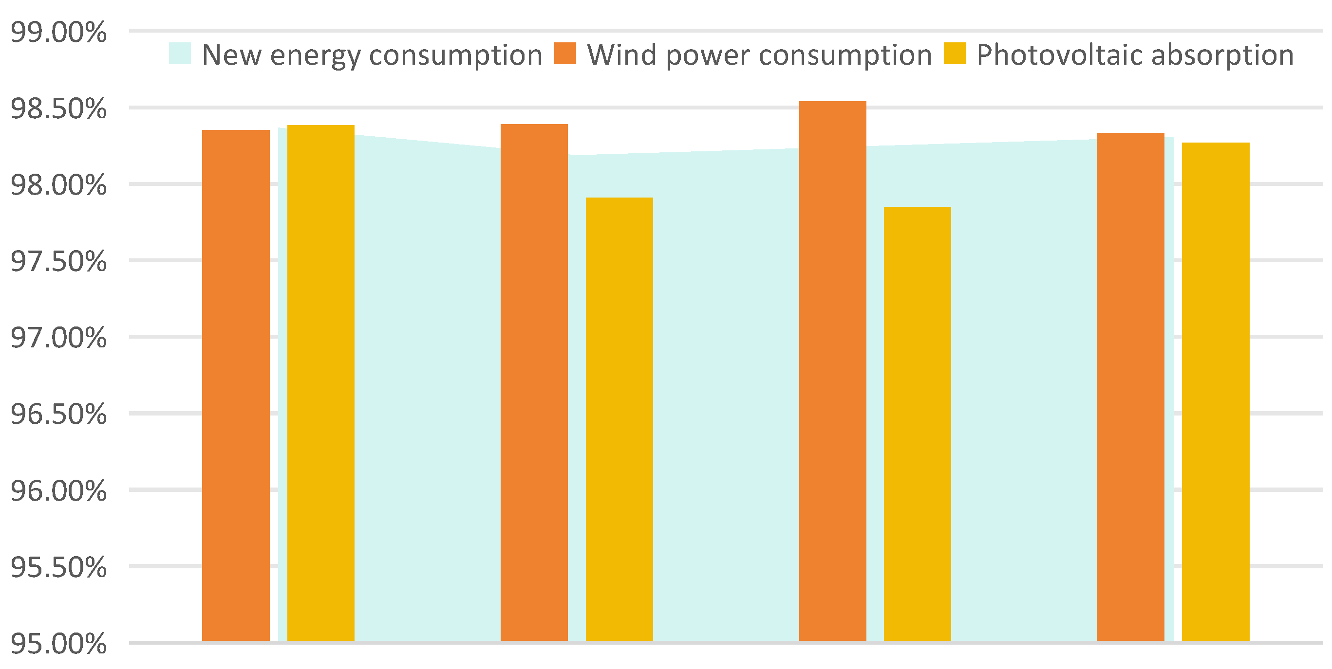
By analyzing
Table 1 and
Figure 2, which illustrate the participation of energy storage in renewable energy accommodation, it can be observed that under the hybrid energy storage strategy, the renewable energy accommodation rate of the power grid reaches 98.37%, which is 0.07% to 0.18% higher than that of single-type energy storage strategies.
This difference primarily stems from the distinct characteristics of different energy storage technologies: Lithium iron phosphate batteries are suitable for short-term regulation but have limited discharge duration. Compressed air energy storage (CAES) offers large capacity but responds more slowly. Molten salt thermal storage is ideal for long-duration energy storage but lacks rapid frequency regulation capabilities.
3.2. Hybrid Energy Storage Configuration
By coordinating the advantages of various energy storage technologies, hybrid energy storage achieves more efficient renewable energy accommodation, effectively reduces curtailment, and enhances the stability of the power grid.
The following analysis focuses on the configuration of hybrid energy storage across the entire network. The configuration details of lithium iron phosphate, compressed air, and molten salt thermal storage at each node are presented in
Table 3.
From the analysis of the results in
Table 3, it can be seen that a total of 2429.4 MW/7136.5 MWh of energy storage resources are configured at the seven nodes. Among them, lithium iron phosphate energy storage, due to its low cost, high efficiency, and rapid response characteristics, has a configuration scale of 1307.9 MW/3916 MWh, making it the primary choice for the system. Compressed air energy storage is deployed at Node 16, and the system configures a portion of molten salt thermal storage at Nodes 19, 21, and 24. This indicates that the energy storage configuration requirements in different regions vary significantly, reflecting the differences in power demand characteristics and the capacity for new energy consumption in each region. The hybrid configuration of energy storage, by fully leveraging the advantages of different energy storage technologies, provides the system with greater flexibility and regulation capabilities, better meeting the operational requirements of each region under high new energy penetration conditions.
3.3. Analysis of the Mitigation of Power Fluctuations in Power Systems and Line Regulation Capacity with Hybrid Energy Storage
By analyzing the line congestion situation in
Table 4, it can be found that the lines between Node 3 and Node 4, between Node 7 and Node 8, etc., have congestion or overloading issues, with their line occupancy rates exceeding 77%. Even more severe congestion occurs near Node 14 and Node 21, where the lines are almost fully loaded, with the highest occupancy rate reaching 97.48%.
Node 4 has 5.01 million kilowatts of new energy stations but only 1.45 million kilowatts of load, resulting in the abandonment of new energy. Similarly, Node 7, as a new energy collection node, has a large power transmission capacity, and the power on the nearby lines fluctuates. To overcome these problems, the system configures lithium iron phosphate energy storage at Nodes 4, 8, and 32, and compressed air energy storage at Node 16. Through the charging and discharging functions of energy storage, the power fluctuations in new energy are smoothed out, the pressure on line power flow is relieved, and the stability of the system operation is improved. The area from Node 24 to Node 32 has a large load demand, accounting for 47.24% of the total network load. Although there is a ring network that can supply power in multiple directions, there is still a power shortage during peak hours. Therefore, the system chose to configure long-term energy storage molten salt thermal storage at Nodes 21 and 24, etc., to meet the load demand in this area and optimize the operation of the power grid.
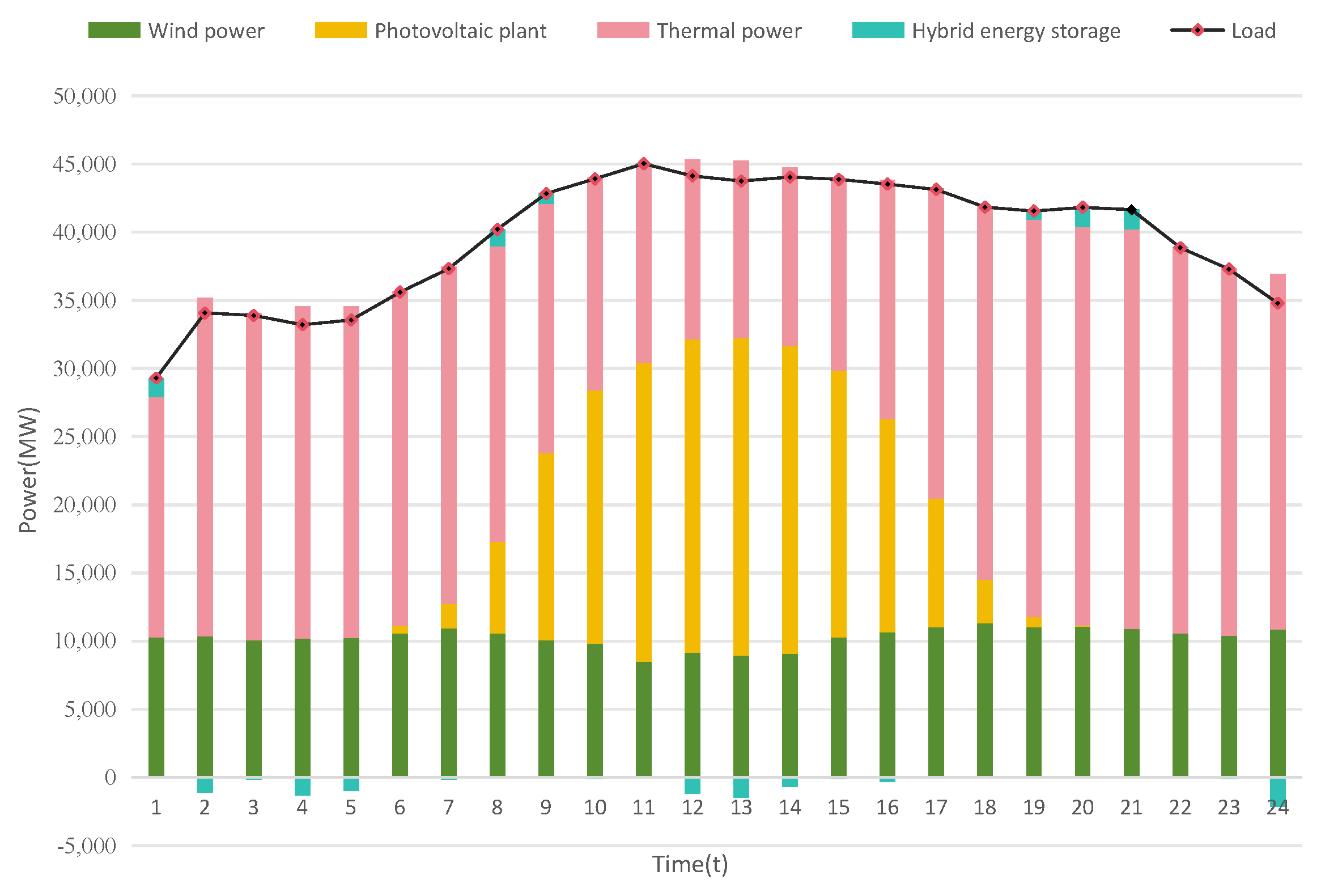
By analyzing the charging and discharging conditions of energy storage, as shown in
Figure 3, the energy storage system charges during the 12–14 period when the photovoltaic output is relatively high at noon, and effectively smooths out the load fluctuations through discharging during the peak load period of 19–21, optimizing the consumption rate of new energy. Meanwhile, lithium iron phosphate storage performs well in handling short-term power fluctuations, while molten salt thermal storage, through longer charging and discharging cycles, undertakes more long-term regulation tasks.
4. Conclusions
This paper proposes an optimal configuration model for hybrid energy storage with the high penetration of new energy. The analysis of the results shows that
The optimal configuration of hybrid energy storage effectively enhances system flexibility. In scenarios with the high penetration of new energy, the hybrid energy storage system can significantly improve the flexibility of the power grid. By rationally configuring lithium iron phosphate energy storage, compressed air energy storage, and molten salt thermal storage, the power grid can more stably meet load demands when responding to fluctuations in renewable energy output, alleviate line congestion, and enhance the safety and reliability of system operation.
Different types of energy storage have their own advantages and work in synergy. Lithium iron phosphate energy storage is suitable for rapid response and short-term regulation; molten salt thermal storage has a longer discharge cycle and is suitable for balancing long-term load changes; compressed air energy storage, with its longer charging and discharging capabilities, plays a crucial role in peak shaving and valley filling. The coordinated configuration of the three achieves the efficient utilization of new energy and provides more flexible and diverse solutions by covering the regulation demands across multiple time scales.
Optimizing the placement of energy storage improves the consumption rate of new energy. Through the rational placement of energy storage, the utilization of new energy can be more efficient. Configuring large-capacity shared energy storage at the sites where new energy is aggregated offers dual benefits. This approach not only meets the demand for new energy to be connected to the grid but also effectively reduces the investment pressure on the power grid.
This study presents a novel optimization model for the siting and sizing of hybrid energy storage systems in high-renewable-energy-penetration scenarios. The proposed framework improves system stability and economic efficiency by considering the coordinated operation of storage and renewable energy sources under multiple constraints. A key contribution of this work lies in its incorporation of hybrid energy storage at renewable aggregation stations, offering a more practical and scalable solution for future power systems.
However, this study also has certain limitations. The optimization model relies on representative planning-year data and assumes idealized system conditions. In practical applications, uncertainties such as real-time electricity pricing, regional policy differences, and data granularity may affect the model’s performance. These limitations could influence the generalizability of the results, highlighting the need for further real-world validation and scenario-based analysis.
In future work, we plan to extend the model to include economic dispatch mechanisms under dynamic market pricing and explore how hybrid storage systems can participate in ancillary service markets. Additionally, we aim to develop a hierarchical multi-timescale control strategy that coordinates both fast-response and long-duration storage technologies. Scenario-based stochastic optimization will also be considered to improve model robustness under variable renewable energy conditions.


