1. Introduction
Wind farms are exposed to continually changing meteorological conditions, which can jeopardize their operational integrity under specific conditions. The methodical exposition of the procedure to construct an expert knowledge base for WPP (Wind Power Plant) for the WPPES (Wind Power Plant Expert System) system is the work’s originality. The authors have demonstrated clearly and reasonably how and why a specific knowledge base for the emerging expert system can be constructed. The authors have given their technique (method) for developing inference rules that serve as the foundation for analysis, verification of the established knowledge base, and decision generation. The authors’ endeavor to develop a paper on developing an expert knowledge base for WPP and ES devices is what makes this paper unique. The presentation of the expert system’s organization, including the construction of an expert knowledge base, the development of an expert system’s functional structure, and the presentation of the organization of the method of inference (decision making) on the safety status of the use of wind farm equipment, is also novel in the literature.
The method adopted by the team of authors to visually (logically) illustrate the flow of inference (decision) information (facts, relationships, and rules) in the structure of WPP devices distinguishes this article from previous studies analyzed in the literature. This method of displaying graphs of decision information flow in functional teams of each of the five WPPs and ES proven to be an important factor in confirming the correctness of the WPPES system’s made decisions. During the commissioning and testing of the developed WPPES system, the developed inference graphs were quite useful.
The paper is organized as follows:
Section 1 and
Section 2 provide an introduction and a review of the literature.
Section 3 discusses the approach for building inference rules for expert systems.
Section 4 addresses the issue of diagnosing WPP devices.
Section 5 addresses the problem of developing a set of rules for the expert knowledge base of the WPP wind turbine and the GPO/ES main power connection.
Section 6 offers the results analysis and the collected results.
Intelligent systems in technological applications are described in the literature. They are used to aid in the organization of production and the control of technical and technological operations. Intelligent advising systems are used to make recommendations based on available information in the form of various factors. Furthermore, they take into consideration complicated elements influencing the processes or phenomena under investigation. Work [
1,
2] has made significant progress in this area. These works can be beneficial in the creation of a set of information in the form of inferential rules. These works describe strategies for building knowledge representations, recording them, and analyzing them. The studies described above have the nature of theoretical considerations; they lack a description of actual applications, particularly in the area of overcoming practical challenges while establishing expert knowledge databases. To a limited extent, the literature discusses methodologies and solutions for developing expert knowledge bases based on diagnostic data obtained.
Studies by F. Hayer-Roth, D. Waterman, and others in [
3,
4] described the foundations and mathematical solutions in the field of expert system development, design, and organization. This research can be used to generate sets of inference rules and establish an expert knowledge base.
Intelligent systems in technical and production applications were described in studies by W. Kacalak and others [
5,
6,
7]. This literature provides information on theoretical considerations in the description of methods and analysis (review and sorting) of large sets of information.
S. Duer’s paper [
1,
8] presents actual technical solutions connected to the usage of artificial neural networks in the diagnostics of technical items. The diagnostic information gathered in this manner served as the foundation for the effective development of organizational and technical solutions in the field of building autonomous intelligent renewal systems. The author offered his solutions in the field of diagnostic and expert knowledge database designation, construction, and organization in this work [
9]. Experience in this field was required in order to establish expert knowledge bases, which is the issue addressed in this article.
The papers by L. Bedkowski and others [
10,
11,
12,
13,
14] present the theoretical background of the reliability of technical devices in the operation process. The work presents the issues of modeling technical objects as well as operational and reliability processes in the field of testing their effectiveness. The studies of these authors present practical solutions in the field of modeling technical objects.
Many writers [
15,
16] discuss supporting and intelligent systems. Intelligent systems for diagnostic and quality evaluation supervise or organize technical–technical issues. These systems are useful for analyzing a large number of variables and including intricate factors like technical equipment, tools, manufacturing means, or process conditions and parameters. B. Buchannan and others [
17,
18] contribute greatly. These works explore conclusion rules, knowledge representation, collection, and analysis. Their contributions considerably improve practical solutions while gaining expert knowledge for diagnostics and technical equipment operation. F. Hayer-Roth, D. Waterman, and others’ works on mathematical background in expert system development and organization, including rules for creating expert knowledge bases, conclusion rules, and their analyses, should be considered in this issue.
The development of adequate knowledge bases for expert systems to diagnose wind power plant equipment safety is quite difficult. IT (expert systems, knowledge bases), mathematics (gathering and analyzing knowledge sets), diagnostic (creating models for technical models and organizing significant measurements), reliability-operational (examining project technical conditions), and artificial intelligence are involved. The research by T. Nakagawa and others [
19,
20,
21,
22,
23,
24,
25,
26] presents technical solutions in the field of using diagnostic information to organize the operation of devices and technical facilities. This study describes the problems of modeling technical facilities in terms of presenting their internal structure for the needs of technical service organization.
Iqbal et al. conducted research in [
27], wherein they proposed optimization techniques for wind turbine stability and performance. The optimization involved the application of various methodologies, including predictive and adaptive techniques, resulting in a reduction in the structural loading effects.
No such comprehensive edition on the architecture and organization of an intelligent system (expert system) in practical application exists in the literature on which this work is based. Some discussions of expert systems can be found in the writings of Hayer-Roth, Waterman, and others. Problems with constructing and organizing expert knowledge bases are described as they pertain to expert systems in the aforementioned literature. Decision making (inference) issues related to various types of knowledge bases are the focus of the described methodologies. As can be seen in the literature on expert systems, the issue of inference and decision making remains a significant and systematically addressed one. Buchannan et al. [
17] describe specialized computer programs called “inference modules” in expert systems. There is a close functional relationship between inference modules and knowledge bases, and in many cases, inference modules are important components of knowledge bases. It has been noted in the literature on expert systems that these systems are built in such a way that the inference modules, in conjunction with extended expert knowledge bases, perform the task of processing and analyzing such large amounts of expert knowledge under the control of the inference algorithm developed by the expert, all in real time. In an expert system, the expert knowledge base mandates a specific processing mode for decision making. There is a lack of a comprehensive (complex) presentation of the problems of the expert system construction and organization in the literature describing expert systems, especially in the construction and development of expert knowledge based on a concrete example in the practical application for a particular device.
The article discusses topics such as:
- -
creating models for technical objects, including functional-diagnostic models;
- -
examining technical objects, including technical condition evaluation and the creation of diagnostic signal sets;
- -
determining diagnostic signal sets;
- -
measuring diagnostic signals, including analysis of measurement results and creation of reference diagnostic signal sets,
- -
expert knowledge associated with gathering, analyzing, and concluding an expert system;
- -
mathematical problems, including knowledge set creation, analysis, and conclusions (making decisions).
The literature does not clearly address these difficulties. The article’s cited publications span many themes. This article describes the authors’ strategy to developing (solving) a difficult problem. A comprehensive strategy to developing an expert knowledge base for assessing wind farm equipment safety is innovative. The paper develops guidelines for an expert knowledge base for diagnosing the safety of wind farm equipment.
2. Determining the Diagnostic Knowledge Base for Wind Farm Devices
2.1. Functional–Diagnostic Structure of Wind Power Plant’s Equipment
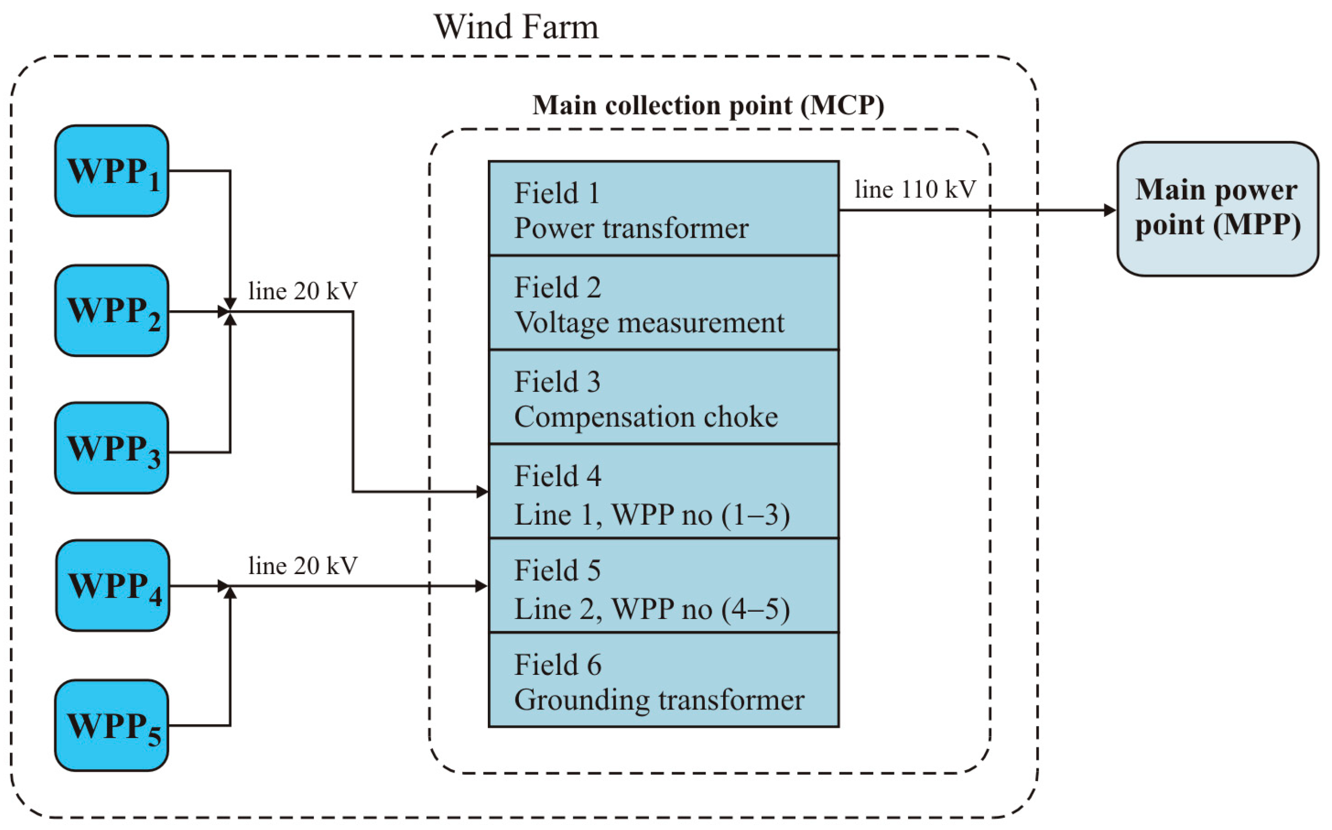
A functional wind farm structure has been developed for the construction of an expert wind farm supervision and safety system (
Figure 1). The designed expert knowledge base concerns a wind farm consisting of five Vestas V90 2.0 MW wind farms connected to the Main Collection Point (GPO) by means of two 20 kV power lines constituting the internal power infrastructure of the wind farm (
Figure 1).
Due to the object’s multilevel method of transformation into an expert knowledge form, the material in this section is presented in stages. The first step involves explaining the basics of how the (WTG) and (WPP) machines work. The second phase involves detailing any problems encountered during the diagnostic evaluation of the tested machinery. By taking this course of action, technical and diagnostic expertise with respect to (WTG) and (WPP) apparatus is gained. In the next paragraphs, we will discuss problems associated with building databases with expert-level information (
Figure 1).
- -
WF is wind farm,
- -
WPP(1–5) is wind power plant, No. 1–5,
- -
MCP is the main collection point,
- -
MPP is the main power point
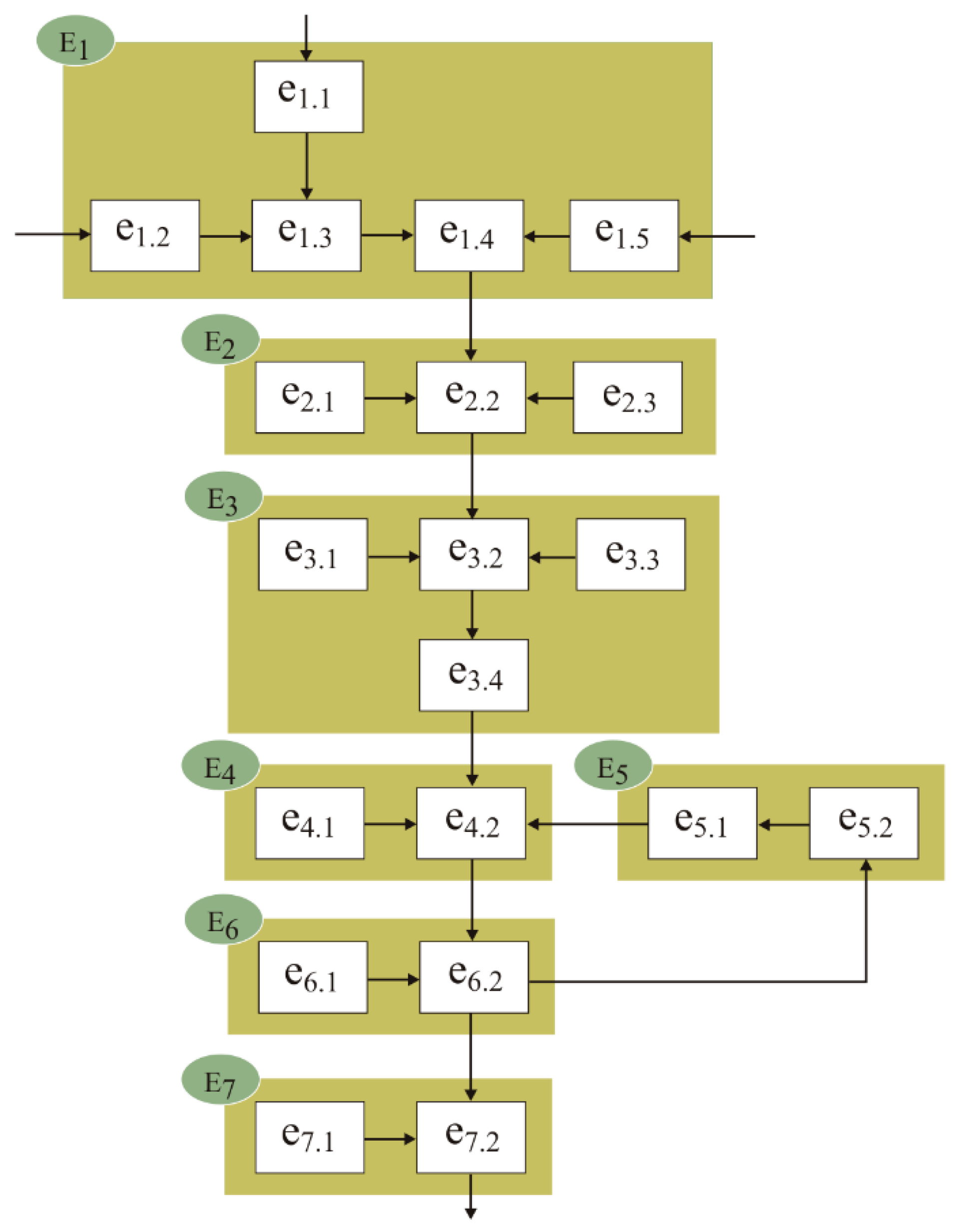
Functional–diagnostic models of technical equipment serve as a foundation for diagnostic research. Consequently, a functional–diagnostic model of the (WPP) was created (
Figure 2 and
Table 1).
- -
E1 is generator drive system,
- -
E2 is synchronous generator system,
- -
E3 is generator’s magnet system,
- -
E4 is power regulator system,
- -
E5 is electric power converter system,
- -
E6 is voltage and current coordinate converter system,
- -
E7 is MV transformer assembly.
In the model of the wind power plant, seven i-functional sets were determined as a result of the functional–diagnostic evaluation. In each i-set, a subset of j-fundamental (functional) elements was determined. The internal structure of the wind power plant model is determined by the set of fundamental elements e
i,j listed in
Table 1.
- -
e1,1, e1,2, e1,3, e1,4, e1,5 is Wind Turbine Generators no. 1–5,
- -
e2,1, e2,2 is MV cable power lines no. 1 and 2,
- -
e3,1 ÷ e3,3 is MV switchgear no. 1–3,
- -
e4,1 is a system for measuring and diagnosing electrical parameters in specific elements of a wind power plant,
- -
e4,2 is a diagnostic system of the wind power plant,
- -
e5,1 is a arcing suppression coil of the wind power plant,
- -
e5,2 is a secondary power transformer of the wind farm,
- -
e6,1 is HV power transformer,
- -
e6,2 is HV Switchgear,
- -
e7,1 and e7,2 is Substation.
The developed functional–diagnostic model of the Wind Power Plant depicted in
Figure 2 served as a basis for determining both a set of diagnostic signals and their respective reference signals.
Table 2 displays the established collection of diagnostic signals X(e
i,
j).
- -
E1 is generator drive system,
- -
E2 is synchronous generator system,
- -
E3 is generator’s magnet system, E4 is power regulator system,
- -
E5 is electric power converter system,
- -
E6 is voltage and current coordinate converter system,
- -
E7 is MV transformer assembly.
2.2. Functional and Diagnostic Structure of a Wind Power Station’s Equipment
Diagnostic tests are performed on technological devices and objects {O(e
i,j)} for evaluation purposes. Additional to cerebral challenges, the item diagnostic test contains technical and technology tasks. These actions yield a functional and diagnostic diagram of the technical object, which determines the diagnostic signals {X
i,j}. The item’s functional units in
Figure 2’s functional and diagnostic diagram are “addressed”. The item’s i-th functional unit is (E
i). Unit elements are “addressed” as (e
i,j), where j-th represents the element’s quantity in the i-th unit. It is accepted that the item’s j-th element or basic module in the structure diagram is indivisible and generates its output signal. This signal measures or diagnoses. With many output signals, just one generalized signal must be determined to best describe the j-th element’s functional (diagnostic, dependability, etc.) qualities. The system calls functional units and basic elements. The third level subunits are intermediate “elements” that enable the bidirectional transition of the item’s hierarchical form into the matrix internal structure (
Table 3 and
Figure 2–4).
- -
e1,1 is turbine shaft stabilization unit,
- -
e1,2 is main transmission,
- -
e1,3 is transmission temperature control system,
- -
e1,4 is clutch,
- -
e1,5 is generator brake,
- -
e2,1 is synchronous generator,
- -
e2,2 is generator temperature control system,
- -
e3,1 is magnetic field winding,
- -
e3,2 is system excitation voltage regulation,
- -
e3,3 is matching system,
- -
e4,1 is PWM inverter assembly,
- -
e4,2 is generator power regulator,
- -
e5,1 is controlled rectifier,
- -
e5,2 is inverter,
- -
e6,1 is UA, UB, UC—three-phase voltage coordinate converter assembly,
- -
e6,2 is current coordinate converter unit IA, IB, IC;
- -
e7,1 is MV transformer temperature control system,
- -
e7,2 is MV transformer unit.
In
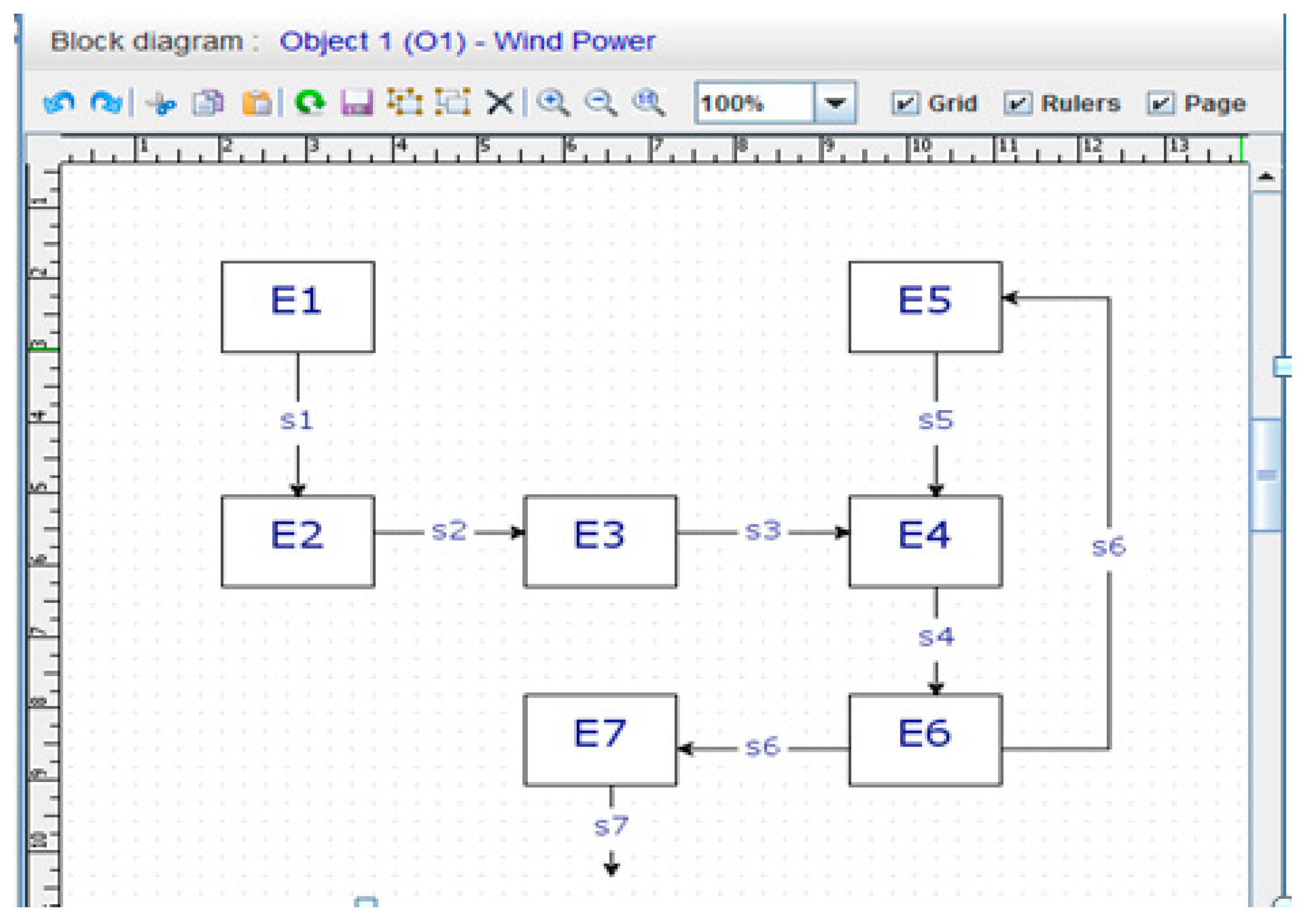
Figure 3 and
Figure 4, diagnostic information from DIAG 2 is used to build a wind farm expert surveillance and safety system. The object’s j-th basic element or basic module is assumed to be an indivisible element-module that creates its output signal. This is a diagnostic or measurement signal. If an element has many output signals, specify just the generalized signal that best represents the j-th element’s functional qualities (diagnostic, reliability, etc.).
- -
E1 is generator drive system,
- -
E2 is synchronous generator system,
- -
E3 is generator’s magnet system,
- -
E4 is power regulator system,
- -
E5 is electric power converter system,
- -
E6 is voltage and current coordinate converter system,
- -
E7 is MV transformer assembly.
The wind farm model’s functional and diagnostic analysis (
Figure 3 and
Figure 4) yields measurement and reference signals such as {X(e
i,j)} at j-functional element outputs.
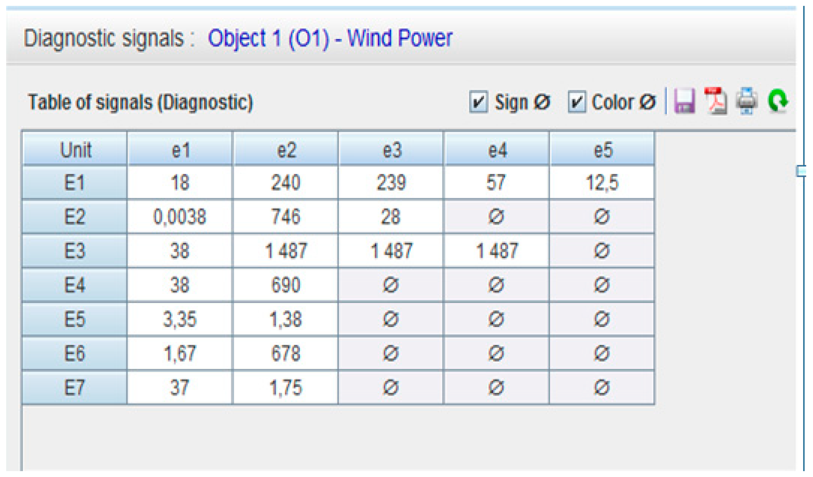
Table 4 displays the wind power plant’s reference and measurement diagnostic signals {X
w(e
i,j)}.
Table 4 displays the reference diagnostic signals {X
w(e
i,j)} for wind turbine generators identified using measurement signal analysis.
3. Construction of the Expert Knowledge Base’s Rule Structure for Wind Farm Equipment
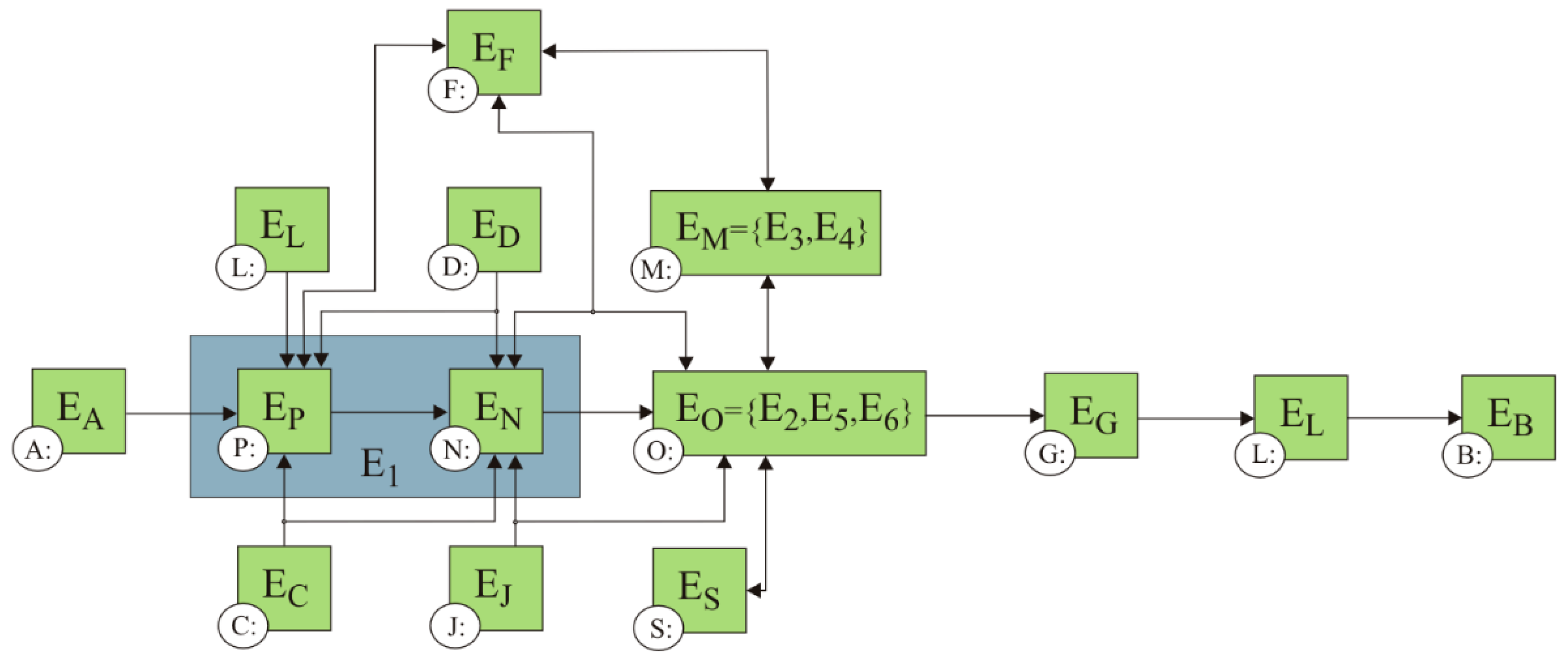
Facts (parameters and working units) about the wind power plant were determined by analyzing the wind power plant’s fundamental components (
Figure 5). This resulted in the identification of two fundamental functional–structure units: a wind turbine generator and a substation (
Figure 5).
Then, for each functional–structure unit, basic blocks comprising equipment, system, and network parameters were determined. Wind turbine generators Symbols in
Figure 5 represent:
- -
A is Environmental and Ambient,
- -
B is Grid, C is Brake Systems,
- -
D is Hydraulics, E is Yaw System,
- -
F is Communications, G is Connectors,
- -
H is Protection Relays,
- -
I is Pitch System,
- -
J is Cooling and Heating Systems,
- -
K is Transmission,
- -
L is MV Unit Power Transformer,
- -
M is Controller,
- -
N is Gearbox,
- -
O is Generator,
- -
P is Rotor.
Items were classified as A–P blocks, where A is Environmental and Ambient, B is Grid, C is Brake Systems, D is Hydraulics, E is Yaw System, F is Communications, G is Connectors, H is Protection Relays, I is Pitch System, J is Cooling and Heating Systems, K is Transmission, L is MV Unit Power Transformer, M is Controller, N is Gearbox, O is Generator, P is Rotor.
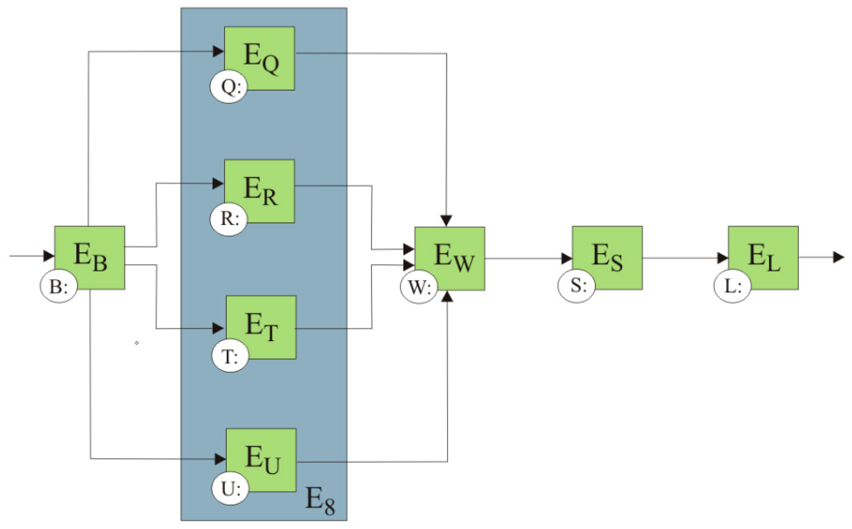
A functional and diagnostic diagram of electrical substation devices is shown in
Figure 6.
- -
Q is Feeder Cable Line Field,
- -
R is Arcing Suppression Coil Filed,
- -
S is Power Transformer Field,
- -
T is Auxiliaries Field,
- -
U is Voltage Measurement Field,
- -
W is General Signalization.
The development of parameters for the entire wind farm, i.e., wind turbine generators (WTGs), medium and high voltage power grids, and the plant’s electrical HV substation (ES), allowed the definition of the facts from which 109 rules for the planned wind farm surveillance and safety system were created. The rules were created for all the developed functional blocks, combining the facts from different blocks together as well, which facilitated a network of mutual relations [
1].
All the rules were presented in a form of the specific dependencies as follows:
Symbols in the dependence 9 represent:
- -
W is result (rule number),
- -
Q is specifies a block’s type for which a specific result is made,
- -
Z is specifies a number of the given result.
Rules (dependence 11) are described in a table as follows:
Ordinal number: specifies numbers of the subsequent rules.
Result: determines the final result for a given rule, according to the Formula (11).
Name: specifies a name of the rule.
Category: defines a given block.
The set of answers: {yes; no}.
Block: defines the symbol of the block for which a given rule was created.
Mathematical description: defines how to create a given rule.
Verbal description: identifies possible causes of failure/malfunction or a given state of work.
Answer: determines whether a rule is met.
Example:
The rule WA1 is to be read as: a name of the rule for the block A (where A—environment and weather conditions)—WTG ready for operation, category—environment and weather conditions, set of answers—[yes/no], mathematical description for the rule is as follows: if there is a rule, e.g., RA001: = PA001< 3.5, then verbal description of this rule is as follows: wind speed is less than Cutin wind speed.
The developed rules correspond to individual wind farm’s operational states. For each rule, in addition to the mathematical description, there is also a verbal description containing the wind farm status data and possible faults/failures, which gives practical support to a dispatcher operating the expert system to supervise and ensure the safety of the wind farm.
The way all the rules are created is shown below using an example of the WA2 rule nominal operation of the wind turbine generator for a normal operational state and the WO3 rule limited operation of the wind turbine generator for a disturbance state.
The example for the WA2 rule nominal operation of the wind turbine generator is presented below. In order to create the WA2 rule necessary parameters (facts) that specify nominal operational conditions for wind turbine generators are determined, which include:
- -
wind speed for nominal operation of the wind turbine generator PA003,
- -
nominal active power PB003,
- -
pitch angle for the Blade A PI001,
- -
pitch angle for the Blade B PI002,
- -
pitch angle for the Blade C PI003.
Then, conditions to be met were defined:
The condition no. 1 wind speed greater or equal to 12 m/s; thus the rule is:
If the dependence (10) exists, then this condition is met.
Answer: Yes
The condition no. 2 wind speed is less than 20 m/s; thus the rule is:
If the dependence (11) exists, then this condition is met.
Answer: Yes
The condition no. 3 WTG in nominal power; thus the rule is:
If the dependence (12) exists, then this condition is met.
Answer: Yes
The above conditions were used to create the rule for the nominal operation of WTG (WA2), which is shown below:
Result: Yes
The example for the WO32 rule limited operation of WTG (disturbance state) is presented below. In order to create this rule, necessary parameters (facts) were defined:
- -
temperature of the generator—phase 1 PO006,
- -
temperature of the generator—phase 2 PO007,
- -
temperature of the generator—phase 3 PO008,
- -
generator alarm PO011,
- -
generator output power reduction due to too high temperature PO012,
- -
wind speed for WTG nominal power PA003,
- -
nominal active power PB003,
- -
main fan in the nacelle PJ001,
- -
thermostat unit failure PJ006,
- -
temperature in the nacelle PJ010,
- -
alarm PH010.
Then, conditions to be met were defined:
The condition no. 1 WTG power reduction due to too high generator’s temperature; thus the rule is:
If the dependence (14) exists, then this condition is met.
Answer: Yes
The condition no. 2 too high temperature of the generator—phase 1, phase 2 or phase 3; thus the rule is:
If the dependence (15) exists, then this condition is met.
Answer: Yes
The condition no. 3 nacelle main fan’s fuse triggered; thus the rule is:
If the dependence (16) exists, then this condition is met.
Answer: Yes
The condition no. 4 nacelle main fan or thermostat failure; thus the rule is:
If the dependence (20) exists, then this condition is met.
Answer: Yes
The condition no. 5 Generator’s output power limited to 75%; thus the rule is:
The above conditions were used to create the WO3 rule for WTG limited power (cooling system malfunction):
Result: Yes
The set of diagnostic rules for the wind power and the electrical substation have been presented in the form of a table.
The CLIPS (C Language Integrated Production System) language implements a forward inference method. During this process, new facts are created corresponding to the operating states for individual units in the wind farm elements. To define these facts, a 3-character symbolism was adopted, preceded by an element identifier (turbine or ES). The first character always indicates letter “W”, the second is the block number, and the third is the operating state of the indicated block. The following sets of operating states were defined for each element and the wind farm itself:
where WF is a set of all possible operating states of a wind farm, WTG is a set of all the possible operating states of a wind farm, ES is a set of all the possible operating states of the main receiving point.
A Set of Expert Knowledge Collection
Statements constitute an important element in the representation of the human specialist knowledge in expert systems. Those statements which correspond to the known and collected facts are one of the main elements of knowledge bases. They concern such issues as events, phenomena, manifestations, and activities. Statements are most frequently written in the form of an ordered triplet:
Dictionaries of the names of objects, attributes and their values are used for the purpose of a simplification of the notation of statements. This enables an identification of notations with the use of labels without a multiple repetition of names. Owing to this, a more economical notation is obtained, one which takes up less place in the computer memory. In general, open dictionaries are applied. Semantic networks and frames are often used for the expression of relationships between objects. It should be emphasized that in the case of multi-value attributes, there appear difficulties connected with the negation of statements in the representation of knowledge with the use of statements. In some systems, statements are written in the form of an ordered quadruple:
while CF coefficient is a degree of certainty which serves the purpose of an expression of uncertain knowledge, the so-called approximate statements. A certain coefficient, which defines the degree of the certainty of a statement, is then assigned to each statement. In general, this is a number from a certain interval, e.g., [−l, l] or [0, l] or [0, 1]. If this coefficient is defined for the first of the intervals mentioned above, then (CF = l) means that the statement is fully true. We know that the statement is false for (CF = −l). (CF = 0) denotes a statement as to which one does not know whether it is true or false. Such statements are determined subjectively. No precise definitions were implemented and the methods of their definition were not formalized, either [
2].
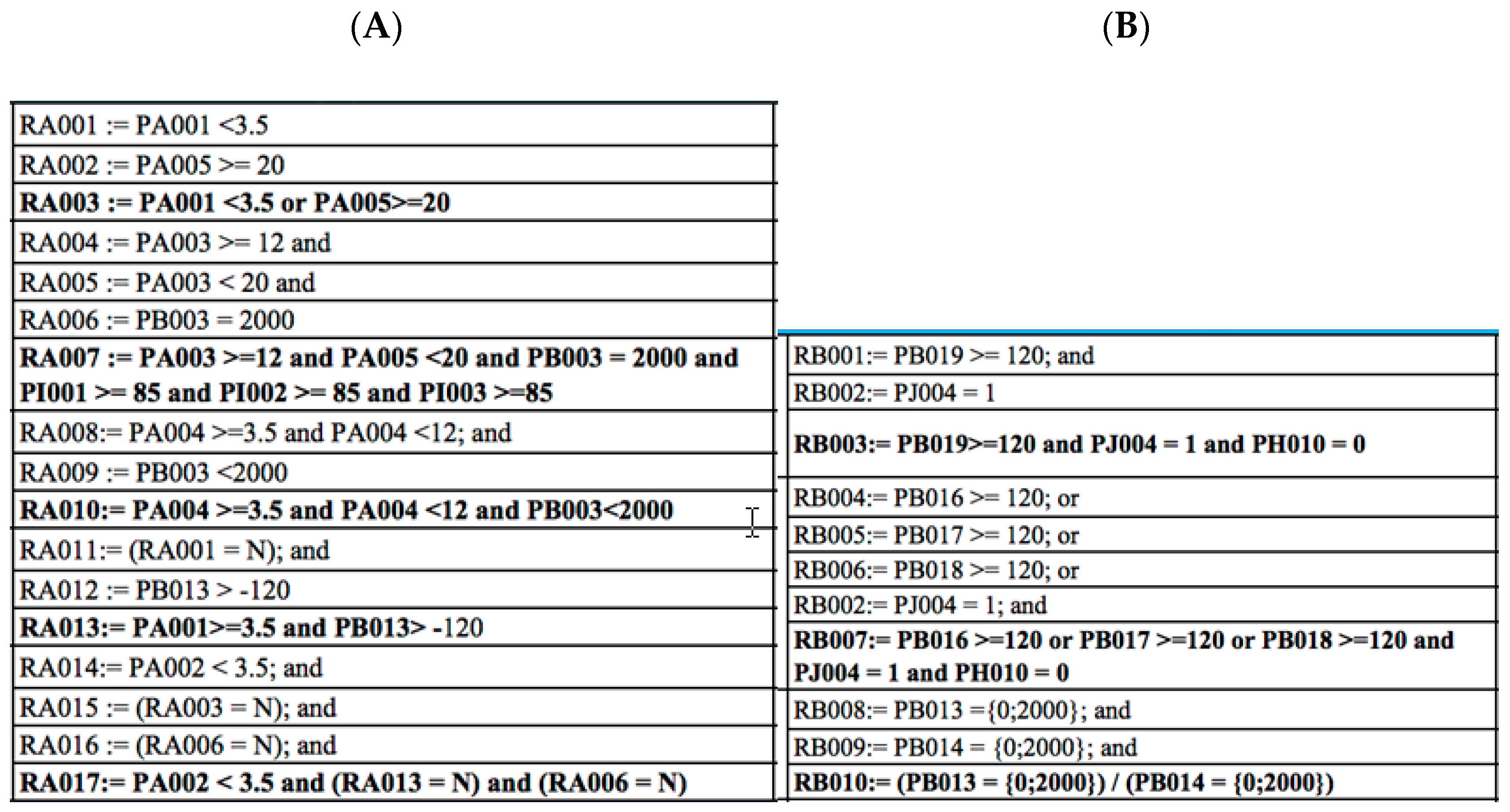
Figure 7 demonstrates example wind turbine generator rules based on Block A’s Environment and Ambient and Block B’s Grid.
4. Results
We define the expert knowledge base as knowledge related to a given field separated from the rest of the system. It contains a set of facts that describe data and input parameters as well as a set of rules that present relationships between these facts.
The functional and diagnostic models developed for the wind power plant and the General Power Output (
Figure 5 and
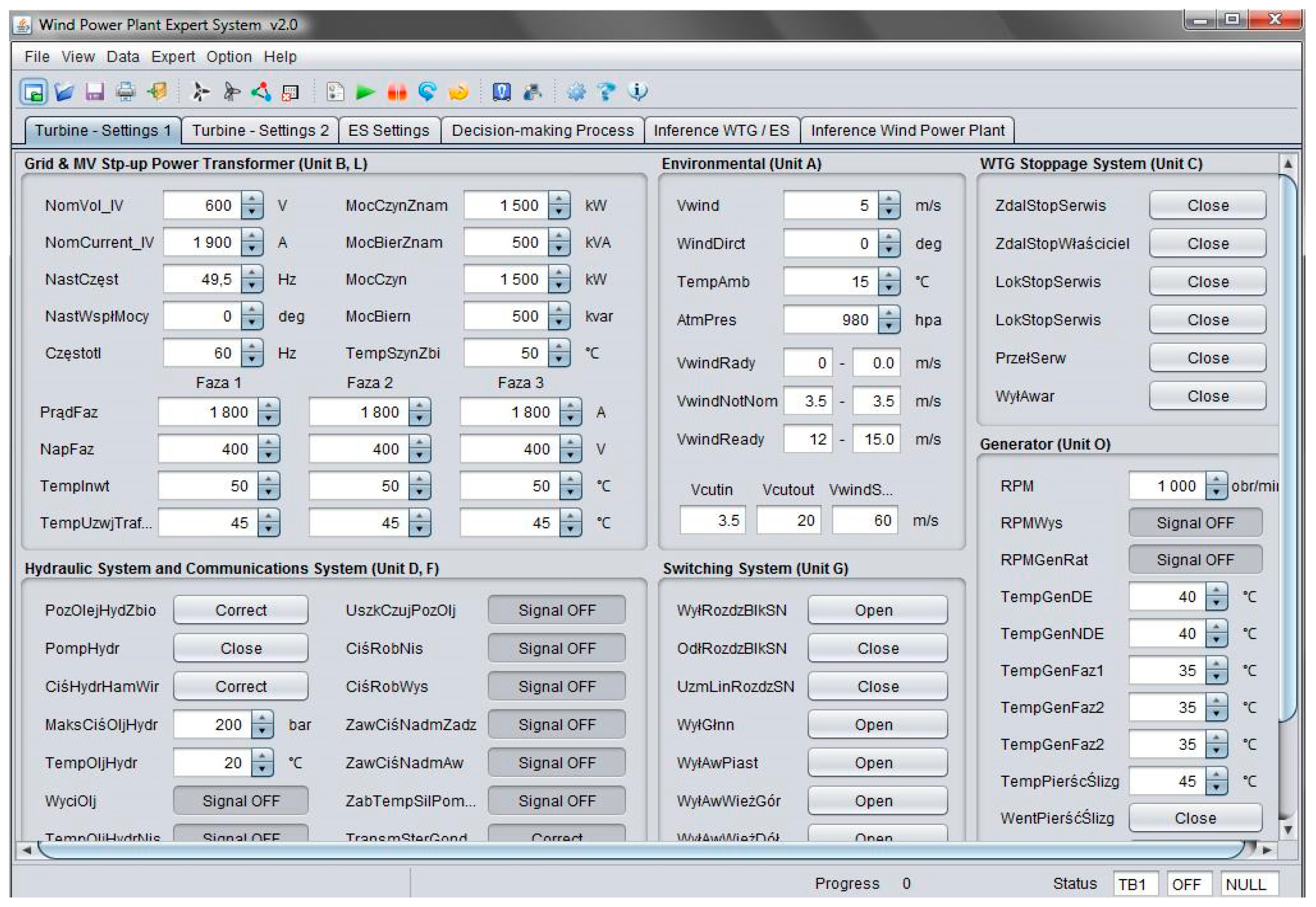
Figure 6) made it possible to distinguish the elementary blocks that group the parameters of individual components, devices and units. Sixteen (16) A-P blocks, for whom 224 facts and 258 rules were created, were defined for a single wind power plant (turbine). Six (6) Q-W blocks, 96 facts and 135 rules were analogically defined for the General Power Output (GPO). Constant sets of facts were additionally created for default values and for several example variants of the functioning of the wind farm. The entire knowledge base (
Figure 8 and
Figure 9) described was placed in separate files which are compliant with the syntax of the CLIPS language, i.e.,
- -
facts.clp: a file that includes a set of the facts of the default values of parameters and several example variants of the wind farm functioning;
- -
gpo.clp: a file that includes a set of rules for all the blocks of the General Power Output and additional rules that define the initial condition of the object;
- -
turbine.clp: a file that includes a set of rules for all the blocks of the wind power plant and additional rules defining the initial condition of the object;
- -
windfarm.clp: a file that includes templates and functions that determine the working condition of the wind farm and auxiliary rules, e.g., the starting (initiating) rule.
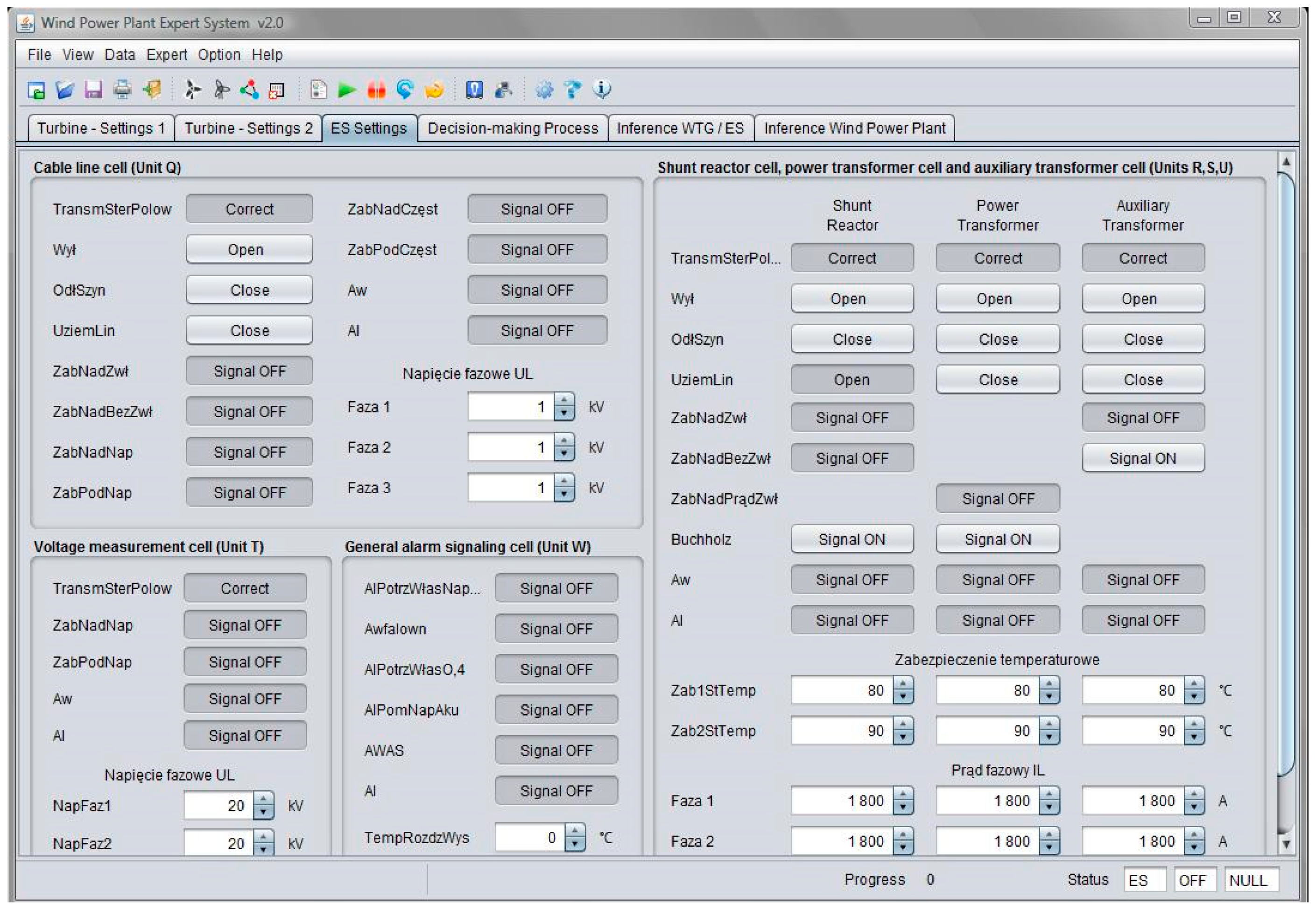
Owing to the division of knowledge into the thematic parts placed in external files, it was possible to obtain large clarity and an ease of edition. In each group of facts related to the wind power plant and the General Power Output (GPO), several to dozen or so parameters were included, whose number depends from the function and quantity of devices included in a given block. These parameters are divided into groups, and they are available in the first three panels that describe the setting of wind power plants and the General Power Output, which is presented in
Figure 8 and
Figure 9.
To determine the characteristic values for each fact, 13 categories were developed according to which the individual facts were defined. The categories define the following among others: the object, voltage, direction, block, type, symbol, abbreviation, unit, condition, default, minimum and maximum value. All the facts and rules described according to the above-mentioned categories are placed in the table which is available in source.
One may notice in
Figure 8 and
Figure 9 that the reserve parameters for the blocks of the wind power plant and of the General Power Output were neglected. In the process of the implementation of the knowledge base in the CLIPS language, the common five-sign symbols were accepted both for facts and rules. The first sign of the symbol indicates a fact when it accepts letter P or a rule in the case of the occurrence of letter R. The subsequent sign determines the number of the block which a given fact or rule belongs to. The last part is a three-digit number attributed to a given parameter.
The symbol is additionally expanded to include an identifier with the number of the wind power plant or of the General Power Output placed at the beginning as a prefix. As the names of blocks in the various elements of the wind farm do not repeat, one may determine in an explicit manner which type of the element we are dealing with. In the case of the occurrence of the WTG01RB003 symbol, we know that it indicates rule 3 of Block B in turbine number 1. This rule means an occurrence of the signal of stopping of the work of the turbine because of too high a temperature of the bus bars.
5. Discussion
Extremely complex is the issue of creating expert knowledge bases for intelligent (advisory) decision support systems. These databases are complex due to their organization, structure, and development techniques. The article discusses building an expert knowledge base for wind farm equipment, such as Wind Turbines (WTG) and the Main Power Supply Point: Electrical Substation (ES). The expert knowledge base created for wind farm equipment includes the following subsets of data: measurements, facts, relationships and dependencies, as well as diagnostic and inference rules. The novelty of this article is, among other things, the systematic presentation and description of the subsequent stages of building an expert knowledge base. In the initial phase of constructing an expert knowledge base, the Wind Farm WF’s components, including the WTG and ES, are diagnosed.
This action produces the measurement knowledge base designated for the WTG and ES. The measurement (diagnostic) knowledge base serves as the foundation for determining the set of facts directly related to and describing the conditions and properties associated with various events related to the operation of the Wind Power Plant and the Main Supply Point. The studies present the issues associated with the development of a set of facts for wind farm equipment. In the second phase of constructing an expert knowledge base, diagnostic and inference rules for WPP and ES devices are developed. The article utilizes a “decision tree” to construct a database of expert knowledge. This strategy necessitates a particular procedure for developing an expert knowledge base. For this purpose, the functional structure of the wind farm is depicted as a branching “structure tree” comprising the Wind Power Plant and the Main Power Supply Point. Then, each of these devices is presented in
Figure 5 and
Figure 6 as a block functional structure.
In WTG, 16 functional blocks were distinguished in the set {A, B, …, P}. There are six functional blocks in ES marked in the set {Q, R, ..., W}. In the third stage of building an expert knowledge base, the process of building a set of diagnostic and inference rules for WTG and ES devices is carried out. For this purpose, a general form of the rule was developed, which is presented in the form of dependence (12). The rules developed at the very beginning of their construction were assigned an analytical form. This form of rules is convenient (appropriate) for building a rule in the form of a mathematical dependence. The dependency in this form was implemented in the CLIPS computer language in the further process of building the knowledge base, and it was saved in the set of rules.
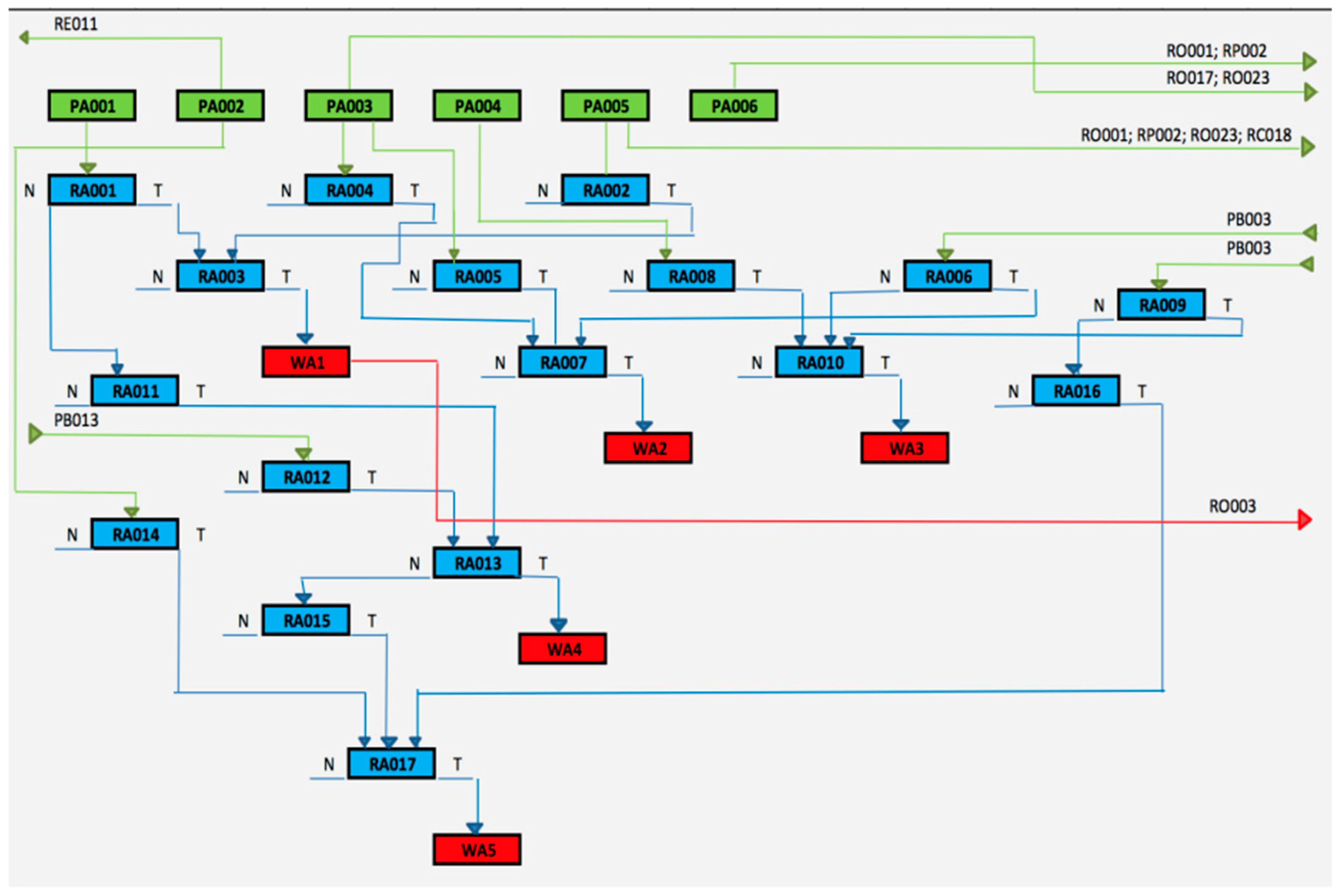
In the study, in the form of Relationships (2 to 11) the rules developed for Block A are presented: Environment and external conditions. On the other hand,
Figure 10 presents the rules for Block A: Environment and external conditions processed into an analytical form.
The symbols in
Figure 10 represent the following:
- -
PAno (green in
Figure 10) is an elementary number of facts in BlockA: environment and external conditions,
- -
RAno (blue in
Figure 10) is an elementary number of rules in BlockA Block: environment and external conditions,
- -
WAno (red in
Figure 10) is an elementary number of decisions in Block A Block: environment and external conditions.
A novelty in this article in relation to other studies on this subject is a methodical presentation of support in relation to building expert knowledge bases with the use of graphs: graphic models of the decision information flow in the structure of the “decision tree” for WTG and ES devices. This flow of diagnostic information was presented for all the 16 functional blocks in WTG and for 6 blocks in ES. The graphical approach to solving the problem of developing a decision on the use of WTG and ES proved to be appropriate, both at the stage of building the knowledge base and in subsequent work during the launch and testing of the WPPES program.
Figure 10 shows an example of a “decision tree” graph for Block A: Environment and external conditions. The method of constructing the “decision tree” graphs for individual wind farm blocks is shown on the example for Block A. The primary issue in the process of building the graphs was the definition of facts and diagnostic parameters for both the wind farm and ES. The next step in this process was the creation of inference rules for the expert system.
Rectangles were assigned to the parameters that appear in dependences (10 to 19), which were marked with symbols compliant with the method of describing parameters appearing in the constructed rules for the expert system. The facts are marked green, the rules are marked blue, and the results are marked red. Facts defined as a reserve (with the possibility of a further expansion of the system) are marked gray. Each block was divided into several tree chart windows, the number of which depended on the number of facts for a given block and the appropriate level of information complexity as well as the type of devices, networks and installations that constitute them. As a rule, fact numbering should be described in the upper part of the “decision trees” window. An important step in the presentation of the “path” of the decision information flow in each block of the “decision tree” was the assignment of the facts and the line connection to the relevant rules. The output information designated in the form of a decision rule is derived from a given block of the “decision tree” as the target result. Due to the fact that the rules were created from facts from different blocks of the “decision tree”, the rule was adopted to place the markings for a given rule symbol in the window where the facts were stored. On the other hand, in the window of a given rule, there is also a symbol of the fact used to create a given rule. This principle organized the structure of the creation of the “decision tree” and made it possible to easily navigate through other information flow windows in the blocks of the “decision tree”.
Each graphical form of a “decision tree” of the decision information flow in a given block of the “tree” structure contains the information entering that block and the generated output information. The output information from each block of the “decision tree” containing inferring information is analyzed when developing a decision on the fitness of wind farms or GPO.
6. Conclusions
The primary issue in expert systems are knowledge bases. Each expert system requires a specialized set of information that is an expert knowledge base. For this purpose, specialized data sets are created by specialists, that is to say information sets concerning: specialized data sets—information sets ensuring the transfer of expert knowledge to a computer program. The development of specialized data sets requires extensive engineering knowledge about a technical object being examined. An important element of these knowledge bases are the rules used in expert systems during the process of developing decisions. At this stage of the expert system’s work, the language of communication between the system and the user through the graphic interface through which the communication takes place is very significant. The entire knowledge base stored in the expert system can be accessed multiple times by a large number of users, i.e., computer users who seek advice. On the other hand, the computer returns the best, in its opinion, advice to us and, if necessary, explains the logic on the basis of which the initial conclusions arose. We also refer to the systems used when a person, despite having extensive knowledge on a particular subject, is unable to utilize it optimally.


 ,
, 


