Article

Recovery of Waste-Activated Carbon for Synthesizing High-Efficiency ORR Electrocatalyst

1
Tianjin Key Lab of Biomass/Wastes, School of Environmental Science and Engineering, Tianjin University, Tianjin 300072, China
2
School of Science and Engineering, Shenzhen Institute of Aggregate Science and Technology, The Chinese University of Hong Kong, Shenzhen 518172, China
*
Author to whom correspondence should be addressed.
Energies 2025, 18(7), 1666; https://doi.org/10.3390/en18071666
Submission received: 19 February 2025 / Revised: 6 March 2025 / Accepted: 20 March 2025 / Published: 27 March 2025

Abstract

Activated carbon used to adsorb organic pollutants and heavy metals in wastewater is often used to prepare precursor materials to avoid re-polluting the environment. Non-precious metal and heteroatom co-doped electrocatalysts have emerged as promising alternatives to Pt-based catalysts due to their high catalytic activity and remarkable stability. This has greatly developed the ORR process in the field of energy storage, which is restricted due to the high price of Pt-based catalysts. In this study, bamboo shavings were pre-activated to synthesize carbon materials, which were subsequently mixed with an oil phase to simulate “waste-activated carbon”. The results demonstrate that the modified waste-activated carbon exhibits a high specific surface area, a well-developed porous structure, and characteristic element doping, which collectively contribute to the effective construction of active sites. Furthermore, the material displays ORR electrocatalytic performance that surpasses that of commercial Pt/C catalysts. In this study, a high-performance ORR electrocatalyst was successfully synthesized through the retreatment of “waste-activated carbon”. Building on this achievement, this study offers a novel perspective and contributes to advancing research on the resource utilization and sustainable treatment of waste-activated carbon.

1. Introduction

Activated carbon has been demonstrated to be an effective and environmentally sustainable adsorbent due to its exceptionally high specific surface area and porous structure [1] and has been extensively used in gas-phase adsorption, denitrification, desulfurization oil, gas recovery [2], liquid-phase adsorption [3,4] catalyst carrier [5], and energy storage materials [1,6]. The disposal of waste-activated carbon (WAC) presents a significant environmental challenge due to its limited adsorption capacity and the presence of specific hazardous contaminants. Improper disposal methods, such as incineration or landfilling, can result in secondary environmental pollution and resource wastage [2]. Therefore, it is an urgent need to develop effective strategies for the regeneration of WAC to enable its value-added reuse.
Oxygen reduction reaction (ORR) [7] is a vital cathode reaction in energy storage and conversion devices such as fuel cells and metal–air cells [8,9]. The low cathodic ORR rate generally requires Pt-based electrocatalysts to facilitate the reaction process. However, the high cost, limited availability, and poor stability of these materials significantly impede the advancement of fuel cells and metal–air batteries [8]. In contrast, carbon-based electrocatalysts offer a promising alternative for the ORR, demonstrating high electrocatalytic activity while being both cost-effective and environmentally friendly [10,11,12]. M-Nx-C catalysts made of nitrogen-doped carbon embedded with transition metals (e.g., Fe, Co, and Ni) are candidates to replace traditional Pt-based electrocatalysts [13]. M-Nx-C catalysts can even be more effectively used for cathodic ORRs due to their abundant active sites and high stability [14]. The doping of nitrogen can create the ligand structure derived from the carbon skeleton, which can anchor the metal ions at specific positions and produce active sites; the doping of transition metals can lead to the production of more metal nanoparticles in the carbon skeleton and facilitate the graphitization of carbon materials, thus enhancing the electrocatalytic performance of the catalysts [14,15,16]. Metal doping of WAC induces a reorganization of its pore structure, thereby restoring its original adsorption capacity and creating active sites for the electrocatalytic ORR [17]. This process facilitates the effective reuse of activated carbon.
In this study, WAC was simulated by mixing the oil phase with bamboo chip-derived AC. Magnesium hydroxide carbonate (Mg5(OH)2(CO3)4) was used as a foaming agent to create mesoporous and macroporous activated carbon, forming a unique pore structure in the oil–carbon mixture for a graded porous carbon-based catalyst. Ferric chloride and urea served as the Fe and N sources to prepare the ORR electrocatalyst. Characterization confirms the successful pore structure and high specific surface area. Through calcination and doping processes, this study fully utilizes the characteristics of oily activated carbon to develop materials with excellent electrocatalytic properties. Electrocatalytic performance tests demonstrated that the incorporation of the oil phase significantly enhances both the electrocatalytic activity and cycle stability of the ORR. Furthermore, density functional theory (DFT) simulations of the material surface revealed that the increase in positive electrostatic potential following doping facilitates the adsorption of hydroxyl (·OH) species, thereby accelerating the ORR process. This strategy provides an effective and sustainable approach for the reprocessing and resource utilization of waste-activated carbon, highlighting its potential as a valuable material for advanced energy applications.

2. Materials and Methods

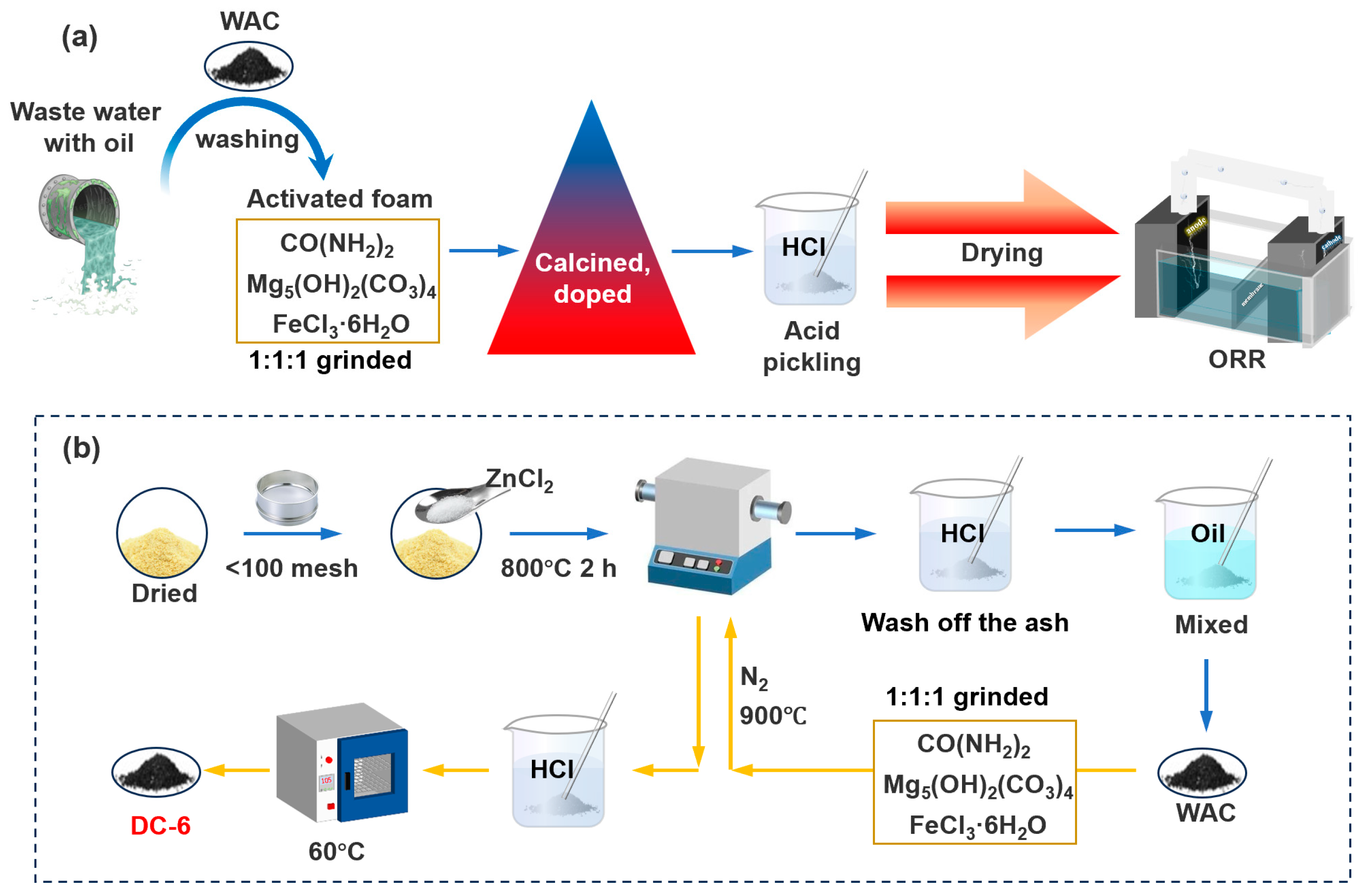
2.1. Synthesis of Activated Carbon

As depicted in Figure 1a, the schematic representation delineates a three-stage regeneration protocol for oily waste-activated carbon, comprising sequential activation, acid treatment, and structural reconstruction, which ultimately yields an efficient ORR electrocatalyst. The corresponding experimental procedures are detailed in Figure 1b. Initially, bamboo shavings were dried at 60 °C, mechanically pulverized, and sieved to achieve a particle size below 100 mesh. Subsequently, 9.0 g of the processed bamboo shavings was homogeneously blended with 9.0 g of ZnCl2 and thoroughly ground into a fine powder. The mixture was subsequently pyrolyzed in a programmable tube furnace under a continuous nitrogen atmosphere, employing a heating rate of 10 °C/min from ambient temperature to 800 °C, with a subsequent isothermal retention period of 2 h. The resulting carbonized product underwent sequential HCl washing to remove residual ash and vacuum drying at 105 °C to obtain the final activated carbon material.
Two grams of carbon material were directly mixed with diesel oil (0, 6, and 12 g) to simulate WAC after oil adsorption. After further activation as mentioned below, they were labeled as DC-0, DC-6, and DC-12, respectively. Subsequently, 2 g of carbon material was separately mixed with 6 g of crude oil from Daqing (DY-6) and lubricating oil (DR-6) to examine the effects of different oil types. Additionally, 2 g of inactivated carbon material was combined with 6 g of diesel oil, and the resulting mixture was labeled as DC-N following activation. The deactivated activated carbon here refers to activated carbon that has not been treated with activators (ZnCl2 and Mg5(OH)2(CO3)4).
The WAC was mixed with urea (CO(NH2)2), basic magnesium carbonate (Mg5(OH)2(CO3)4), and ferric chloride (FeCl3·6H2O) in a 1:1:1:1 mass ratio. The mixture was then mechanically ground for 10 min until a homogeneous blend was achieved. Subsequently, the mixture was calcined at 900 °C with a heating rate of 10 °C·min−1 under a nitrogen (N2) atmosphere and held at this temperature for 1 h. The resulting powder was washed multiple times with 1 M hydrochloric acid and deionized water to remove residual activators and achieve neutrality. After drying at 60 °C, the carbon-based catalyst was obtained.

2.2. Electrochemical Tests

Electrochemical characterization was performed using a standard three-electrode configuration connected to a CHI 760E electrochemical analyzer (Chenhua Instruments, Shanghai, China). The system comprised three components: a 5 mm diameter glassy carbon disk coated with synthesized catalyst as the working electrode, a Ag/AgCl reference electrode (calibrated at +0.059 V vs. RHE), and a platinum wire auxiliary electrode. Catalyst ink formulation involved homogenizing a 5 mg carbon catalyst in a blended solution containing 700 μL of isopropyl alcohol, 250 μL of deionized water, and 50 μL of 5 wt% Nafion dispersion via 60 min ultrasonication. The precise deposition of 10 μL of catalyst ink (mass loading: 250 μg·cm−2) onto mirror-polished GC substrates was followed by ambient air drying. Commercial Pt/C (20 wt%) electrodes were fabricated using identical protocols.
Prior to RDE/RRDE measurements, 0.1 M KOH electrolyte underwent 30 min gas purging (N2/O2) to establish saturation conditions. Cyclic voltammetry analysis was performed between −0.628 and +0.172 V (vs. Ag/AgCl) at a 10 mV·s−1 scan rate. Oxygen reduction kinetics were evaluated through linear sweep voltammetry (10 mV·s−1) under varied rotation speeds (400–2000 rpm, Δ400 rpm increments). All electrode potentials were normalized to the RHE scale according to the conversion formula: ERHE = ESCE + 0.059(pH) + 0.059 V.

2.3. Catalyst Characterization

Scanning electron microscopy high-resolution transmission electron microscopy (HRTEM-Tecnai G2 F30, Thermo Fisher Scientific, Eindhoven, The Netherlands) and the energy-dispersive spectroscopy (EDS-Xplore 30, EDAX Inc., Mahwah, NJ, United States) analyzer were employed to observe the morphology, microstructure, and element distribution, respectively. The crystallographic structure, composition, and surface properties were determined by X-ray diffraction (XRD-D8 Advance, Bruker, Karlsruhe, Germany), Raman spectroscopy, and X-ray photoelectron spectrometry (XPS-K-Alpha, Thermo Fisher Scientific, Cheshire, United Kingdom), respectively. The specific BET surface area and pore size distribution (Dymax Corporation, Torrington, CT, United States) were assessed and obtained in a gas adsorption analyzer.

2.4. Simulation Details

Computational simulations were performed using Gaussian 09 software (EM64L version) with the density functional theory (DFT) framework [18,19]. The B3LYP/6-311G(d,p) basis set was selected due to its optimal balance between computational accuracy and resource efficiency, particularly for characterizing non-covalent interactions and surface property modifications. To address dispersion effects in the standard DFT approach, we implemented the DFT-D method incorporating pairwise energy corrections [7], which effectively compensates for the inherent dispersion description limitations of the 6-311G(d,p) basis set.
Post-processing analyses were conducted through Multiwfn 3.8 software to derive electrostatic potential distributions and reduced density gradient functions [20]. Visualization workflows employed VMD 1.9.3 to generate three-dimensional representations, including isosurface plots and color-mapped atomic charge transfer diagrams [21]. These graphical outputs provided an intuitive characterization of property evolution in functionalized carbon materials.

3. Results and Discussion

3.1. Physicochemical Characterization
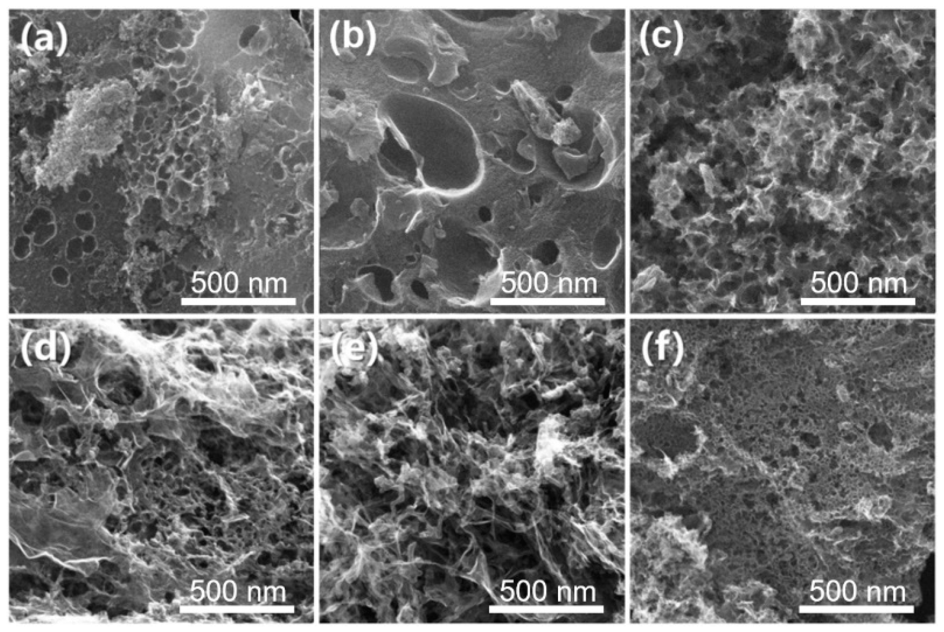
3.1.1. Morphology

The SEM images presented in Figure 2 reveal the morphological characteristics of DC-N, DC-0, DC-6, DC-12, DY-6, and DR-6. Following activation with multiple chemical agents, all WAC-derived electrocatalysts demonstrated a pronounced and heterogeneous porous architecture. Initial characterization revealed a heterogeneous pore size distribution across the material surface, as illustrated in Figure 2. The comparative analysis in Figure 2b–d demonstrates the significant influence of oil absorption on the morphological evolution of the carbon matrix. Specifically, DC-6, DC-12, and DY-6 samples exhibited a well-defined 3D honeycomb-like porous architecture. These findings suggest that the incorporation of diesel fuel serves as a critical structural determinant in the formation of 3D hierarchical pore networks within the activated carbon framework. These 3D honeycomb pores effectively reduce mass transfer resistance and system pressure, improve adsorption efficiency, and potentially enhance ORR activity. This further supports the idea that waste-activated carbon, after adsorbing oil products, becomes a promising material for ORR catalysts [22]. Additionally, it is important to note that the adsorption of lubricating oil did not lead to the formation of more pronounced 3D honeycomb pores, indicating that the type of oil is also critical in determining the pore structure of carbon materials, which may directly influence their ORR performance. Notably, the surface roughness of DC-6 is higher than that of DC-0, suggesting that DC-6 has an obvious macroporous structure on the surface. In DC-12, the pores are interconnected, whereas no such interconnection is observed in DC-6. This indicates that the higher diesel content induces cross-linking, thereby influencing the development of the pore structure. As depicted in Figure 2e,f, the addition of Daqing crude oil and lubricating oil also leads to the formation of pore structures of carbon materials and an obvious cross-linking structure, affecting the specific surface area of carbon materials [23]. The results show that, in addition to the activator, which plays a role in the activation process of pyrolysis, the oil phase and high-temperature pyrolysis process also cause the carbon material to form a richer 3D pore structure, as shown in Figure 2c,e,f [24]. This is conducive to exposing more of the active site, meaning the oil-derived carbon electrical carbon catalyst has high ORR electric catalytic properties. Therefore, from the perspective of adsorption, it can be preliminarily concluded that the oil-based waste-activated carbon regenerated has outstanding advantages in the electrocatalytic ORR process. It is worth mentioning that when comparing Figure 2c,e,f, the surface structure of DC-6 is rougher and more conducive to the construction of the active site. However, the surface of DY-6 exhibits a greater number of large defects, whereas the surface of DR-6 appears smoother. These differences are unfavorable for the increase in specific surface area. This demonstrates that insufficient oil is inadequate for forming a rougher pore structure, while too much oil can cause crosslinking, which ultimately disrupts the pore structure. Therefore, maintaining an optimal oil-to-carbon ratio is crucial as it offers clearer guidance for material selection in the practical application of this technology. It is necessary to conduct a more detailed study of DC-6 to explore its performance in the ORR.
TEM and EDX characterization tests were performed to further discuss the microscopic morphology and distribution of characteristic elements of DC-6, as presented in Figure 3. The HRTEM results indicated that the surface of DC-6 was layered with alternating light and dark areas, thus suggesting a structure with considerable pores [25]. In Figure 3e, Fe is uniformly distributed on the surface of DC-6. It is noteworthy that C and O in DC-6 are more densely distributed than N and Fe because the oil phase will decompose into coke and O-containing functional groups during the pyrolysis process [22]. Figure 3f shows the overall distribution of C, O, N, and Fe on the surface of DC-6, thus suggesting that the uniform distribution of Fe and N is conducive to the generation of more active sites or defects on the surface of DC-6, effectively improving the oxygen reduction electrocatalytic activity of DC-6. This provides physical conditions for the effective use of waste-activated carbon-containing diesel in the ORR.

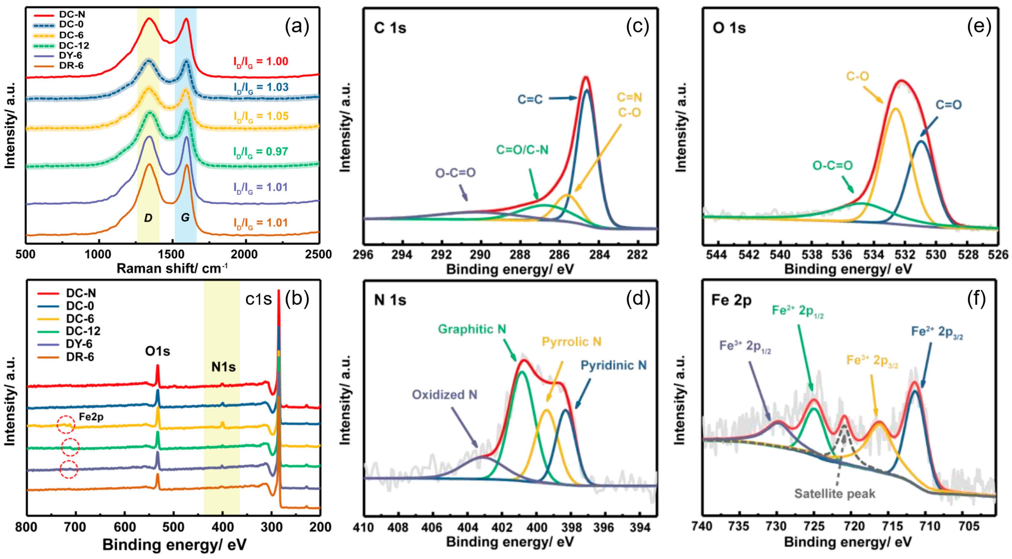
3.1.2. Structure Feature

As summarized in Table 1, the carbon yield following oil–carbon co-pyrolysis was systematically evaluated. For DC-N, which lacked pre-activation treatment, the oil phase exhibited limited infiltration into the carbon matrix due to insufficient pore development. This restricted interfacial interaction between the oil phase and the carbon skeleton resulted in a relatively low carbon yield of 13.3%. In contrast, DC-6, which underwent pre-activation treatment, achieved a significantly higher carbon yield of 24.3%. This enhancement can be attributed to the effective crosslinking and polymerization of the carbon skeleton during the oil phase pyrolysis. Furthermore, previous studies [22] have demonstrated that both oxygen-containing functional groups and aromatic compounds in the oil phase contribute to coke formation, thereby explaining the increased carbon yield observed in DC-6.
Through specific surface area and characteristic pore volume, the structural characteristics exhibited by oil–carbon-derived carbon-based electrocatalysts can be seen intuitively. The specific surface area (SBET) of DC-N was 417.69 m2·g−1 and the total pore volume (Vtotal) was 0.374 cm3·g−1, which were significantly lower than those of DC-6, indicating that the mixture of carbon materials and the oil phase was not uniform without pre-activation treatment, and the limited pore structure prevented the infiltration of activator into the carbon skeleton. Thus, the oil interaction and activation were not fully played, resulting in poor pore structure of DC-N. In contrast, the pore structure of DC-6 was rich, and the specific surface area and total pore volume reached 1596.4 m2·g−1 and 0.934 cm3·g−1, respectively, indicating that the pre-activated carbon material had a pore structure dominated by micropores, which can make the diesel oil and activator penetrate more effectively and play a pore-forming role. The major reason for the above result is that the oil-phase component is capable of producing pores and increasing the specific surface area of pores when the growth chain breaks at high temperatures. However, when the diesel mass increased to 12 g, the specific surface area value of DC-12 decreased to 515.89 m2·g−1 and the total pore volume decreased to 0.373 cm3·g−1, suggesting the pyrolysis process produces too much coke, which in turn clogs the pores, thus resulting in a poor activation effect and affecting the formation of specific surface area and abundant pores. Furthermore, the microporous volume (Vmicro) of DC-6 was 0.694 cm3·g−1, which was significantly higher than that of DY-6 (Vmicro 0.356 cm3·g−1) and DR-6 (Vmicro 0.331 cm3·g−1). Accordingly, the mesoporous volume (Vmeso 0.187 cm3·g−1) of DC-6 was slightly lower than that of DY-6 and DR-6. This has a more prominent pore performance than conventional activated carbon [26]. Due to the directional pore-forming effect of the activator, diesel oil is more likely to be used to construct a microporous structure, while Daqing crude oil and lubricating oil are more likely to be used to construct a mesoporous structure. The above results indicate that the DC-6 has a larger specific surface area. This is bound to enable it to bind more active sites, which in turn, is more conducive to the electrocatalytic ORR.
It is evident that the type of oil has a significant impact on the material properties. Both lubricating oil and Daqing crude oil evidently lead to a deterioration of the activated carbon’s pore structure. We believe this is due to differences in the calorific value and viscosity of the various oils. On one hand, diesel has a moderate calorific value, and during pyrolysis at high temperatures, it more readily forms a richer pore structure without generating excessive energy that could cause pore collapse. On the other hand, the viscosity of diesel is relatively well-matched, allowing it to easily remain in the pores of the activated carbon, where it disperses throughout the material’s pore network without causing substantial aggregation. In contrast, lubricating oil and Daqing crude oil behave differently. Under high temperatures, large amounts of these oils can accumulate, leading to further collapse of the material’s pore channels and resulting in pore destruction [27]. Therefore, although both DR-6 and DY-6 contain oil additives, their specific surface area is still lower than that of the undoped activated carbon. This, in turn, negatively impacts the subsequent electrochemical testing.
Raman spectroscopy was used to characterize the defect degree of an oil–carbon-derived carbon-based electrocatalyst, as presented in Figure 4a. At nearly 1340 and 1595 cm−1, there are two distinct characteristic peaks, representing the D peak and the G peak, respectively. The intensity ratio (ID/IG) of the two peaks is obtained to compare the degree of disorder and structural defect of carbon-based electrocatalysis [28]. To be specific, the ID/IG value of DC-N without pre-activation treatment is 1.00, while the ID/IG value of DC-6 after pre-activation treatment is better (1.05), suggesting that full mixing of diesel fuel will be conducive to an increase in defects and active sites in the pyrolysis process, showing a higher ID/IG value. When diesel is not added, the ID/IG value of DC-0 is 1.03, i.e., the effect of a variety of activators and additives can also cause the carbon-based materials to exhibit a high defect degree. Notably, when the diesel hybrid increases to 12 g, the ID/IG value decreases to 0.97, suggesting a decrease in the degree of graphitization enhancement and structural defects. This finding reveals that the excess of diesel will be blocked by pyrolytic carbon material porosity, and the number of active sites and specific surface area decreases, consistent with BET results. In addition, the ID/IG values of DY-6 and DR-6 were also lower than those of DC-6 when comparing the effects of different oil-phase types, suggesting that the specific groups contained in different oil-phase types would affect the production of active functional groups, affecting the graphitization and defect degree of carbon-based materials. The low specific surface area exhibited by DY-6 and DR-6 is related to the type of oil used, particularly the viscosity of the oil. Viscosity influences the diffusion of the oil within the activated carbon and affects its retention behavior in the material’s pores. Lubricating oil has a very low viscosity, typically less than 5 mm2/s at room temperature, which allows it to easily flow through the pores during the adsorption process and accumulate in larger pores. This makes it more prone to pyrolyzing at high temperatures, releasing greater energy and thereby damaging the pore structure. In contrast, Daqing crude oil has a very high viscosity of around 20 mm2/s at room temperature and tends to form clusters during adsorption, which similarly hinders the effective modification of the activated carbon’s pore structure [29]. Diesel, with a viscosity of approximately 10 mm2/s, lies between lubricating oil and Daqing crude oil and thus has a more favorable effect on the formation of the pore structure.
Thus, DC-6 exhibits the highest ID/IG value, i.e., its active site and defect degree are higher, which exhibits the optimal electrocatalytic performance. It is beneficial to increase ORR reactivity.

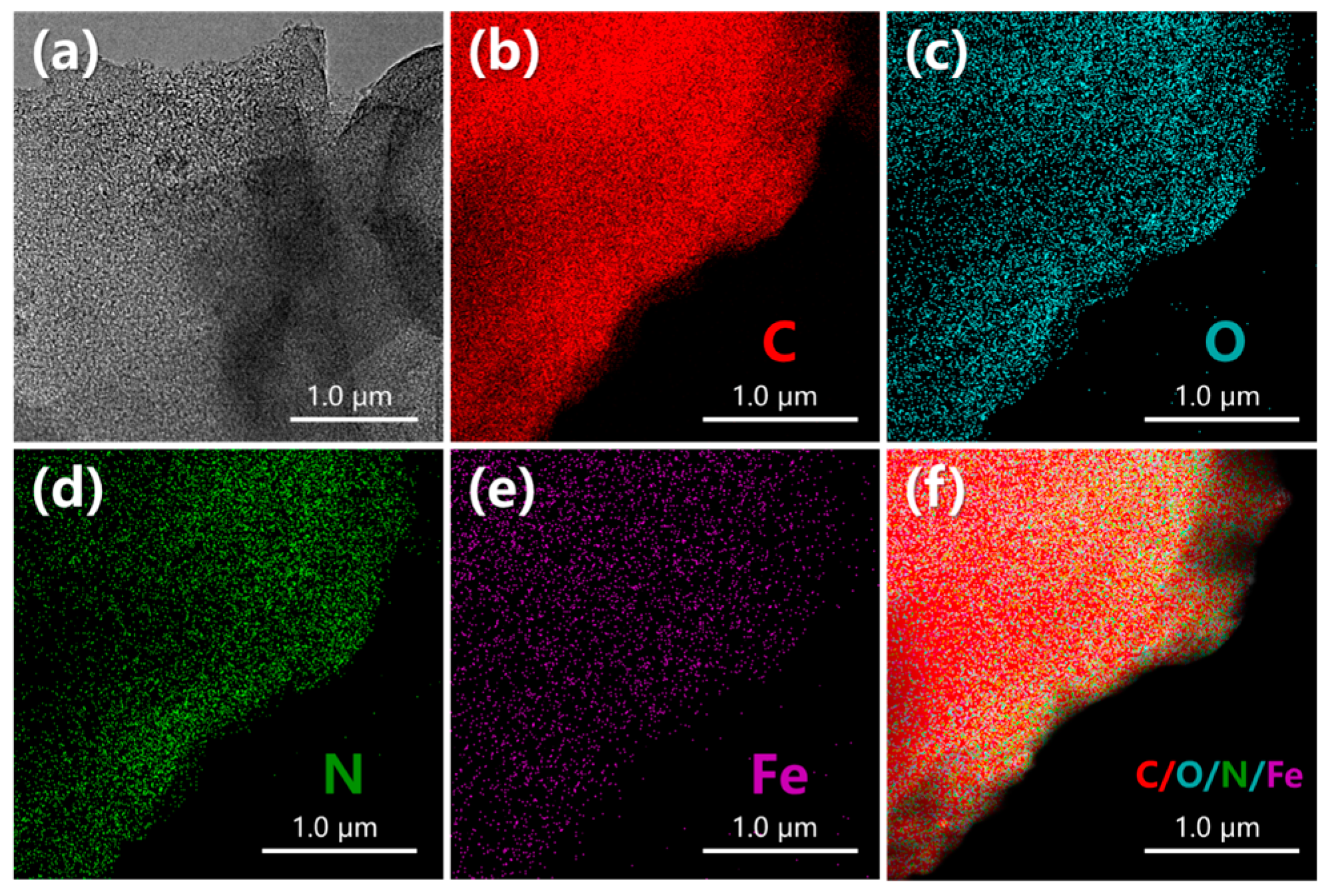
3.1.3. Composition Characteristics

XPS is mainly used to study the surface chemical elements composition and existing states of DC-N, DC-0, DC-6, DC-12, DY-6, and DR-6, as presented in Figure 4d. Three characteristic signal peaks of C 1s, N 1s, and O 1s can be obviously observed in the full spectrum of XPS, which proves that N is adequately doped into the electrocatalyst [7]. In the full XPS spectrum, the peak intensity of N1s represents the content of N in the sample. The N 1s characteristic peak intensity of DC-6 is significantly higher than that of other samples, suggesting that DC-6 contains a high content of N. Since DC-6 has a larger specific surface area and a more developed pore structure, which are both related to the effectiveness of nitrogen doping, this helps explain why the nitrogen content in DC-6 is higher than in the other materials. Table 2 shows the content of C, O, N, and Fe in each sample. The N content of DC-6 at 5.24 at% was significantly higher than that of DC-N (2.04 at%), DC-0 (2.24 at%), DC-12 (1.65 at%), DY-6 (1.98 at%), and DR-6 (1.94 at%). These results agree well with XPS spectra. It is noteworthy that the content of O in DC-6 is 8.24 at%, which is significantly higher than that of other samples, suggesting that more o-containing functional groups will be generated during the pyrolysis of the appropriate oil phase. For the presence of Fe, only weak characteristic peaks of DC-6, DC-12, and DY-6 were observed between 705 eV and 740 eV because the intensity of characteristic peaks was weak due to the low Fe content. The Fe content of DC-6 was 0.41 at% higher than that of DC-N (0.38 at%) because the ferric chloride could not penetrate into the carbon skeleton during the pyrolysis activation process of DC-N without pre-activation treatment, resulting in a decrease in Fe content. The above results indicate that DC-6 has a high content of N and Fe, which means it can easily form the Fe-N structure and generate more active sites to promote the electrocatalytic activity of ORR.
The integral peaks of C 1s, O 1s, N 1s, and Fe 2p in DC-6 are divided by Gaussian functions. Four obvious characteristic peaks can be observed in the high-resolution spectral image of C 1s (Figure 4b), which are C=C (284.6 eV), C=N/C−O (285.6 eV), C=O/C−N (286.7 eV), and O−C=O (290.1 eV) [26], among which the peak area of C=C is the largest. C mainly exists in DC-6 with an sp2 hybrid carbon–carbon double bond, thus suggesting that it has a good graphitization degree and conductivity. In addition, the existence of C=N and C−N verifies that the effective combination of N and C forms the carbon skeleton structure doped with N, which is conducive to improving the electrocatalytic stability of DC-6. In Figure 4c, O 1s has three peaks at 531.0 eV, 532.6 eV, and 534.7 eV, representing C=O, C−O, and O−C=O, respectively [30]. Among them, studies have shown that the presence of oxygen vacancies at 531.0 eV also represents the presence of oxygen vacancies, which can be used as the edge active sites of the carbon skeleton to form edge defects on the surface of the carbon skeleton to promote the adsorption process of the ORR and provide a more favorable microenvironment for the reaction area of the ORR.
Figure 4e illustrates the high-resolution N 1s spectrum, with four characteristic peaks, including pyridine nitrogen (398.3 eV), pyrrole nitrogen (399.4 eV), graphite nitrogen (400.8 eV), and nitrogen oxide (403.1 eV) [31]. The binding energy of 398.3 eV represents pyridine nitrogen, and it was likely to have an Fe−N structure. This result confirms that Fe is capable of forming a coordination structure with N to increase the number of active sites. The doping of N in the process of the ORR was achieved primarily because the two characteristic forms of nitrogen formed by pyridinic-N and graphitic-N are capable of effectively changing the surface properties and electronic structure of the carbon-based catalyst, which is beneficial to enhancing the electrocatalytic performance of ORR. The peak area of various forms of nitrogen was N 1s from high to low: graphite nitrogen > pyridine nitrogen > pyrrole nitrogen > nitrogen oxide, suggesting that the content of functional nitrogen is relatively high, which can increase the electrocatalytic activity of DC-6. In the high-resolution Fe 2p atlas (Figure 4f), two different spin-orbit couplings were largely shown, in which the satellite peak of Fe 2p was nearly 720 eV. It is noteworthy that when the binding energy is nearly 716.5 eV, it also represents the existence of an Fe-Nx structure, corresponding to the peak differentiation result of N, which proves that Fe is adequately doped and forms a stable Fe-Nx valence bond structure with N, thus leading to the formation of more reactive sites for DC-6, and this will directly provide a guarantee for the continuation of the ORR response.

3.2. Electrochemical Characterization

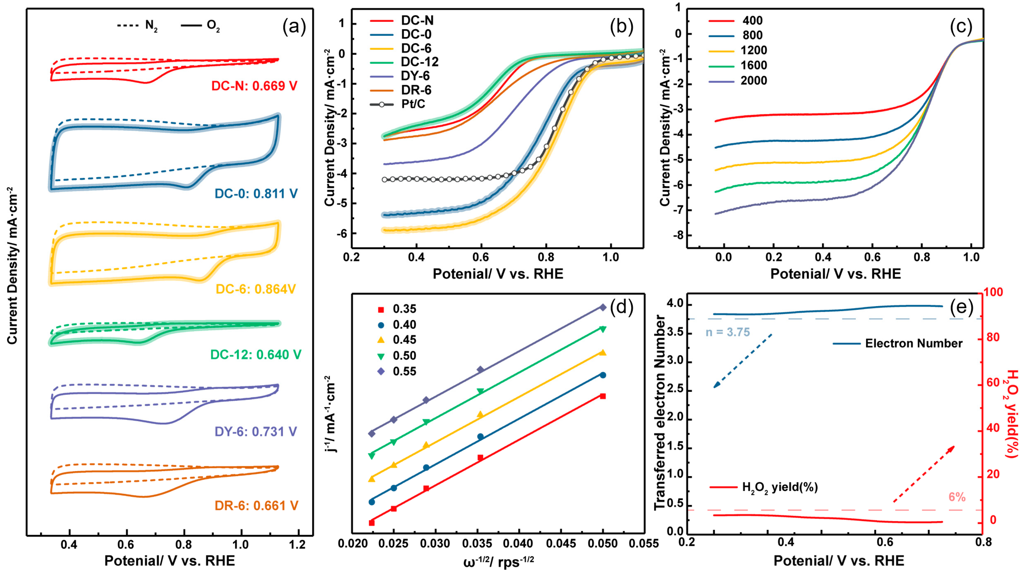
3.2.1. Basic Electrochemical Performance

RDE and RRDE tests were performed on the electrocatalytic performance of oil–carbon-derived carbon-based materials using a three-electrode system. As depicted in Figure 5a, CV curves were obtained by cyclic voltammetry in a 0.1 M KOH solution saturated with N2 and O2 atmosphere at a scanning rate of 10 mV·s−1. The result indicated that DC-N, DC-0, DC-6, DC-12, DY-6, and DR-6 had no reduction peaks in the nitrogen atmosphere (dashed line), whereas they showed obvious reduction peaks in the oxygen atmosphere (solid line), confirming that all oil–carbon-derived carbon-based electrocatalysts exhibit oxygen reduction performance. In DC-N, DC-0, DC-6, and DC-12, the peak potential values (Epeaks) in descending order are 0.864 V (DC-6) > 0.811 V (DC-0) > 0.669 V (DC-N) > 0.640 V (DC-12). The results indicated that the pre-activated carbon-based electrocatalyst DC-6 exhibited optimal ORR activity. When the diesel fuel content increased to 12 g, the ORR performance was significantly reduced under the effect of the blocked channel structure. The peak potentials of DY-6 and DR-6 derived from the other two kinds of oil are 0.731 V vs. RHE and 0.661 V, respectively. It is evident that the redox peaks of DC-6 are higher than those of DR-6 and DY-6, indicating superior redox performance, thus confirming that diesel oil is more beneficial to increasing the electrocatalytic redox properties of carbon-based materials than Daqing crude oil and lubricating oil.
In order to further study the ORR kinetics of DC-N, DC-0, DC-6, DC-12, DY-6, and DR-6, linear cyclic voltammetry was used to measure the LSV polarization curve in 0.1 M KOH solution saturated in an O2 atmosphere at 1600 RPM at the same speed, as presented in Figure 5b. It can be seen that the half-wave potential (E1/2) of DC-N without zinc chloride pre-activation is 0.641 V vs. RHE, which is significantly lower than that of the carbon-based electrocatalyst DC-6 after activation pretreatment, thus suggesting that diesel oil is fully immersed in activated carbon and has enhanced ORR activity [32]. As shown in Table 3, a comparison of DC-0, DC-6, and DC-12 carbon-based electrocatalysts with different diesel-added qualities, the half-wave potential of DC-6 is 0.822 V vs. RHE, which is higher than that of DC-0 (0.781 V vs. RHE, E1/2) and DC-12 (0.610 V vs. RHE, E1/2), suggesting that the addition of the appropriate amount of diesel fuel can promote the catalytic performance of ORR. This result is consistent with the order of peak potential value in CV. The half-wave potential and limiting diffusion current density of DC-6 was significantly higher than DY-6 (E1/2 0.703 V, J0.3V 3.691 mA·cm−2) and DR-6 (E1/2 0.649 V, J0.3V 2.889 mA·cm−2) in different oil phase types. Compared with commercial Pt/C, the half-wave potential of DC-6 shows a negative shift of 18 mV, but the limit diffusion current density (J0.3V) of 5.895 mA·cm−2 is significantly higher than that of commercial Pt/C (J0.3V is 4.216 mA·cm−2). This suggests that the surface of the DC-6 material exhibits a faster mass transport rate and reaction rate. In contrast, the other materials show the opposite behavior. The half-wave potential of the other materials synthesized in this study is more negative, and their limiting current densities are more positive, indicating significantly poorer performance compared to the commercial Pt/C catalyst. The above results indicate that DC-6 has the best ORR performance compared with other oil-derived carbon-based electrocatalysts and is superior to commercial-grade Pt/C.
With the use of the LSV test method, LSV curves of DC-6 at different speeds (including 400 rpm, 800 rpm, 1200 rpm, 1600 rpm, and 2000 rpm) were analyzed, respectively, as presented in Figure 5c. The limit diffusion current density also increases with the increase in rotational speed. Precisely because the diffusion distance is small at a high rotational speed, a better ORR kinetics process is displayed. In accordance with the Koutecky–Levich (K-L) equation in Figure 5d, the number of transferred electrons (n) in the reaction process is slightly more than 4, and J−1 has a linear relationship with ω−1/2, suggesting that the oxygen reduction process of DC-6 is a four-electron pathway. It is noteworthy that the K-L equation (e.g., oxygen solubility, diffusion coefficient, and viscosity coefficient) values are ideal, whereas there may be slight deviations in the actual measurement, resulting in obtaining an electron number slightly more than 4.
Accordingly, the ring current and disk current were collected using the RRDE three-electrode system at 1600 rpm in an O2-saturated 0.1 M KOH solution to further verify the transfer electron value (n) and hydrogen peroxide yield (H2O2%) during the ORR [9,18]. As depicted in Figure 5e, the average number of transferred electrons is 3.91, which is close to 4 electrons, and the hydrogen peroxide production rate of below 3% is far lower than that of commercial-grade Pt/C.

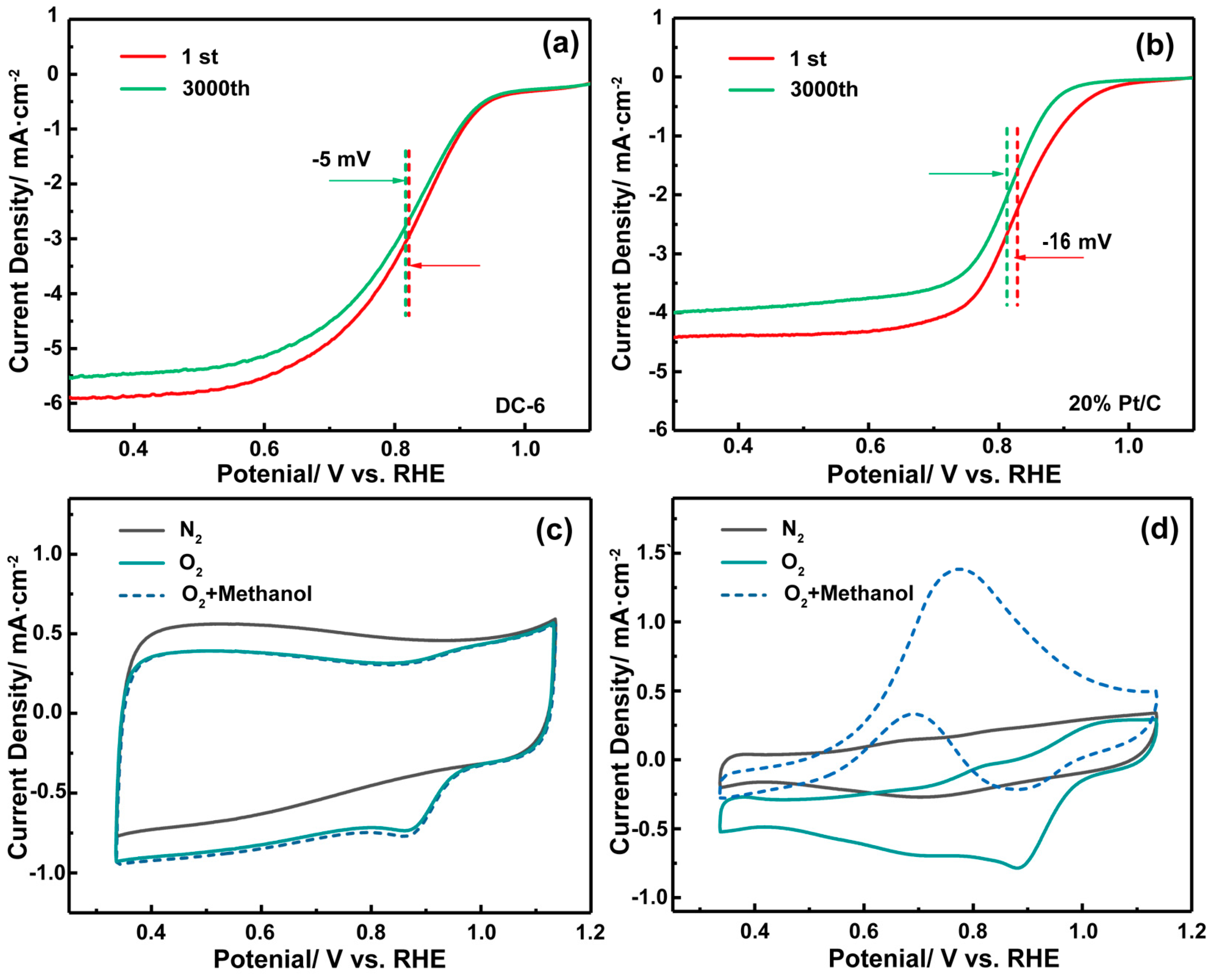
3.2.2. Methanol Resistance and Cycle Stability

As depicted in Figure 6a, the half-wave potential in LSV polarization curves of DC-6 and 20 wt% Pt/C was compared after a cyclic charge–discharge process with a sweep speed of 50 mV·s−1 and a sweeping number of 3000 cycles. It can be found in Figure 6b that the half-wave potential drop △E1/2 in DC-6 is −5 mV while △E1/2 of commercial-grade Pt/C is −16 mV. This phenomenon indicates that the half-wave potential drop in commercial-grade Pt/C is larger after 3000 cycles of the charging and discharging process, which proves that the poor cyclic stability of Pt/C leads to a decrease in ORR reactivity. DC-6, on the other hand, shows better long-term cyclic stability because the stable chemical bond structure in DC-6 improves the durability of the carbon-based electrocatalyst. Through methanol resistance and cyclic stability, it can be concluded that DC-6 can still show relatively high ORR electrocatalytic reaction activity in complex scenes and long-term use.
Based on the high ORR reactivity of DC-6, the methanol resistance and long-term cycle stability of DC-6 were investigated. As depicted in Figure 6c,d, DC-6 and 20wt% Pt/C were examined in a 0.1 M KOH solution and 0.1 M KOH + 1 M methanol solution saturated with O2 to obtain the CV curve. For DC-6, the current density and oxygen reduction performance did not change significantly after the introduction of the 1 M CH3OH solution. However, for 20 wt% Pt/C, the current density fluctuated greatly, and the oxygen reduction peak disappeared, suggesting that DC-6 has a stronger tolerance to the methanol solution than commercial-grade Pt/C. The type of oil used has varying effects on the modification of activated carbon for the preparation of ORR materials. Among them, diesel exhibited a more favorable impact, whereas Daqing crude oil and lubricating oil did not show significant improvements. Therefore, waste-activated carbon adsorbed with oil-contaminated diesel wastewater is more suitable for the preparation of ORR materials. It can be seen that the reuse of waste-activated carbon has excellent properties.

3.3. Structure–Activity Relationships and Catalysis Mechanism

From DFT simulation analysis, it can be concluded that after Fe and N are doped, the surface properties of the waste carbon material change, especially the electrostatic potential, as shown in Figure 7. It also shows that after Fe and N doping, the proportion of the electrostatic potential of waste carbon materials changes. As shown in Figure 7a, the original electrostatic potential of the material is mainly concentrated near −15 kcal·mol−1, while the electrostatic potential of most of the modified areas is concentrated at −5 kcal·mol−1, and there is an electrostatic potential higher than 25 kcal·mol−1, which will obviously be more conducive to the adsorption of negatively charged groups (mainly *OH). It can also be seen that the local area centered on Fe exhibits a higher potential distribution, which is bound to become the active center of the ORR, as shown in Figure 7b. This is also reflected in Figure 7c. Compared with the original carbon material, the amount of charge is reduced after Fe is doped, 1.73 electrons are transferred, and the charge of the entire carbon material is reduced, which is also conducive to the adsorption and analysis of *OH, which in turn can promote the ORR. The above analysis echoes this experiment.

4. Conclusions

This article explores the modification of waste-activated carbon after oil adsorption and its application as a catalyst for the ORR. It performed well with considerable pores and a high specific surface, showing high ORR electric catalytic performance and stability, to realize “waste-activated carbon” in electrocatalysis efficient use.
(i)
Reprocessed waste-activated carbon played a crosslinking role in the process of pyrolysis and activation of the honeycomb porous structure. In addition, it shows that Fe and well-doped N are evenly distributed on the surface of DC-6. This is very important for the structure of the microenvironment of the ORR area and for maintaining the continuity of the reaction. This is also proven by the DFT calculation.
(ii)
The carbon yield of DC-6 (24.3%) is significantly higher than that of DC-N (13.3%). The main reason is that the oil phase can take place in the pyrolysis process of cross-linking polymerization while retaining the original pore structure of coke products and increasing the carbon yield. When using waste-activated carbon, care should be taken to control the proportion of oil.
(iii)
It is found that DC-6 has an ORR pathway close to four electrons, and the yield of hydrogen peroxide produced in the reaction process is less than 3%, which is much lower than that of commercial-grade Pt/C (about 40%). In addition, DC-6 is superior to commercial-grade Pt/C in long-term cycle stability and methanol resistance.
The substantial accumulation of waste-activated carbon necessitates urgent treatment solutions. This study aims to not only alleviate environmental pressures but also create additional industrial value through resource utilization. Furthermore, critical issues such as catalyst poisoning resistance will be thoroughly investigated and addressed in the future to ensure practical applicability.

Author Contributions

Writing—original draft, Z.T.; resources, supervision, and funding acquisition, F.L.; visualization, formal analysis, H.L.; software, X.J.; investigation, methodology, K.L. All authors have read and agreed to the published version of the manuscript.

Funding

This work was supported by the Young Elite Scientists Sponsorship Program by Tianjin (TJSQNTJ-2020-13) and the National Natural Science Foundation of China (52322005).

Data Availability Statement

Informed consent was obtained from all subjects involved in the study.

Conflicts of Interest

The authors declare no conflicts of interest.

References

  1. Tang, Q.; Wang, L.; Xue, Z.; Li, C.; Lv, D.; Zhang, N.; Zhu, K. Free-standing sulfur/carbon nanocomposite cathodes for lithium–sulfur rechargeable batteries. ACS Appl. Nano Mater. 2024, 8, 863–870. [Google Scholar] [CrossRef]
  2. Suresh, D.; Goh, P.S.; Kang, H.S.; Ahmad, M.N.; Ismail, A.F. Waste reutilization in pollution remediation: Paving new paths for wastewater treatment. J. Environ. Chem. Eng. 2024, 12, 113570. [Google Scholar] [CrossRef]
  3. Ye, S.; Zhu, J. Application and Development Prospects of Activated Carbon in Heavy Metal Pollution Treatment. Highlights Sci. Eng. Technol. 2025, 125, 28–32. [Google Scholar] [CrossRef]
  4. Wong, S.; Ngadi, N.; Inuwa, I.; Hassan, O. Recent advances in applications of activated carbon from biowaste for wastewater treatment: A short review. J. Clean. Prod. 2018, 175, 361–375. [Google Scholar] [CrossRef]
  5. Pahasup-anan, T.; Suwannahong, K.; Kampeerapappun, P.; Rangkupan, R.; Dechapanya, W. Conditional optimization on the photocatalytic degradation removal efficiency of formaldehyde using TiO2–nylon 6 electrospun composite membrane. Appl. Sci. Eng. Prog. 2025, 18, 7509. [Google Scholar] [CrossRef]
  6. Dupre, K.; Ryan, E.M.; Suleimenov, A.; Goldfarb, J.L. Experimental and computational demonstration of a low-temperature waste to by-product conversion of US oil shale semi-coke to a flue gas sorbent. Energies 2018, 11, 3195. [Google Scholar] [CrossRef]
  7. Reckien, W.; Janetzko, F.; Peintinger, M.; Bredow, T. Implementation of empirical dispersion corrections to density functional theory for periodic systems. J. Comput. Chem. 2012, 33, 23–31. [Google Scholar] [CrossRef]
  8. Zhou, Z.; Zhang, H.J.; Feng, X.; Ma, Z.; Ma, Z.F.; Xue, Y. Progress of Pt and iron-group transition metal alloy catalysts with high ORR activity for PEMFCs. J. Electroanal. Chem. 2024, 959, 118165. [Google Scholar] [CrossRef]
  9. Tang, C.; Titirici, M.; Zhang, Q. A review of nanocarbons in energy electrocatalysis: Multifunctional substrates and highly active sites. J. Energy Chem. 2017, 26, 1077–1093. [Google Scholar] [CrossRef]
  10. Jia, Y.; Wang, Y.; Zhang, G.; Zhang, C.; Sun, K.; Xiong, X.; Liu, J.; Sun, X. Pyrolysis -free formamide-derive d N-dope d carbon supporting atomically dispersed cobalt as high-performance bifunctional oxygen electrocatalyst. J. Energy Chem. 2020, 49, 283–290. [Google Scholar] [CrossRef]
  11. Gusiatin, M.Z. Advantages of Co-pyrolysis of sewage sludge with agricultural and forestry waste. Energies 2024, 17, 5736. [Google Scholar] [CrossRef]
  12. Zhang, X.; Cheng, X.; Zhang, Q. Nanostructured energy materials for electrochemical energy conversion and storage: A review. J. Energy Chem. 2016, 25, 967–984. [Google Scholar]
  13. Lu, Z.; Yao, S.; Dong, Y.; Wu, D.; Pan, H.; Huang, X.; Wang, T.; Sun, Z.; Chen, X. Earth-abundant coal-derived carbon nanotube/carbon composites as efficient bifunctional oxygen electrocatalysts for rechargeable zinc-air batteries. J. Energy Chem. 2021, 56, 87–97. [Google Scholar]
  14. Zhang, Y.; Wang, X.; Zheng, S.; Yang, B.; Li, Z.; Lu, J. Hierarchical cross-linked carbon aerogels with transition metal-nitrogen sites for highly efficient industrial-level CO2 Electroreduction. Adv. Funct. Mater. 2021, 31, 2104377. [Google Scholar] [CrossRef]
  15. Niu, H.; Lin, S.; Chen, Y.; Feng, J.; Zhang, Q.; Wang, A. Hydrogel derived FeCo/FeCoP embedded in N, P-codoped 3D porous carbon framework as a highly efficient electrocatalyst for oxygen reduction reaction. Appl. Surf. Sci. 2021, 536, 147950. [Google Scholar] [CrossRef]
  16. Han, Z.; Feng, J.; Yao, Y.; Wang, Z.; Zhang, L.; Wang, A. Mn, N, P-tridoped bamboo-like carbon nanotubes decorated with ultrafine Co2P/FeCo nanoparticles as bifunctional oxygen electrocatalyst for long-term rechargeable Zn-air battery. J. Colloid Interface Sci. 2021, 590, 330–340. [Google Scholar]
  17. Akula, S.; Mooste, M.; Kozlova, J.; Käärik, M.; Treshchalov, A.; Kikas, A. Transition metal (Fe, Co, Mn, Cu) containing nitrogen-doped porous carbon as efficient oxygen reduction electrocatalysts for anion exchange membrane fuel cells. Chem. Eng. J. 2023, 458, 141468. [Google Scholar]
  18. Frisch, M.; Trucks, G.; Schlegel, H.; Scuseria, G.; Robb, M.; Cheeseman, J. Gaussian 16 Rev. C.01. Wallingford, CT2016. Available online: https://gaussian.com/g09citation/ (accessed on 19 March 2025).
  19. Zhao, H.; Tang, Z.; He, M.; Yang, X.; Lai, S.; An, K.; Han, S.; Qu, Z.; Zhou, W.; Wang, Z. Effect of oxygen functional groups on competitive adsorption of benzene and water on carbon materials: Density functional theory study. Sci. Total Environ. 2023, 863, 160772. [Google Scholar]
  20. Zhu, C.; Shi, Q.; Xu, B.; Fu, S.; Wan, G.; Yang, C. Hierarchically porous M-N-C (M = Co and Fe) single-atom electrocatalysts with robust MNx active moieties enable enhanced ORR Performance. Adv. Funct. Mater. 2018, 8, 1801956. [Google Scholar] [CrossRef]
  21. Humphrey, W.; Dalke, A.; Schulten, K. VMD: Visual molecular dynamics. J. Mol. Graph. 1996, 14, 33–38. [Google Scholar] [CrossRef]
  22. Taxi, D.; Shao, S.; Maimaitiyiming, X.; Sawut, A.; Tursun, M.; Kuerban, Z.; Lin, H. Biomass carbon with defective structures as effective ORR catalyst for DMFC. Sep. Purif. Technol. 2025, 356, 129775. [Google Scholar]
  23. Liu, X.; Wu, H.; Chen, S.; He, J.; Yang, Z.; Cheng, J.; Wu, J. Study on the alkali-free three-component flooding system in the Daqing oilfield. ACS Omega 2024, 9, 16006–16015. [Google Scholar]
  24. Xiong, Z.; Syed-Hassan, S.S.A.; Hu, X.; Guo, J.; Qiu, J.; Zhao, X.; Su, S.; Hu, S.; Wang, Y.; Xiang, J. Pyrolysis of the aromatic-poor and aromatic-rich fractions of bio-oil: Characterization of coke structure and elucidation of coke formation mechanism. Appl. Energy 2019, 239, 981–990. [Google Scholar]
  25. Yu, H.; Wang, W.; Lin, F.; Li, K.; Yan, B.; Song, Y.; Huang, C.; Chen, G. A facile and green strategy to synthesize N/P co-doped bio-porous carbon with high yield from fungi residue for efficient VOC adsorption. Sep. Purif. Technol. 2021, 276, 119291. [Google Scholar]
  26. Yusop MF, M.; Abdullah, A.Z.; Ahmad, M.A. Amoxicillin adsorption from aqueous solution by Cu (II) modified lemon peel based activated carbon: Mass transfer simulation, surface area prediction and F-test on isotherm and kinetic models. Powder Technol. 2024, 438, 119589. [Google Scholar]
  27. Sabitov, A.; Atamanov, M.; Doszhanov, O.; Saurykova, K.; Tazhu, K.; Kerimkulova, A.; Orazbayev, A.; Doszhanov, Y. Surface characteristics of activated carbon sorbents obtained from biomass for cleaning oil-contaminated soils. Molecules 2024, 29, 3786. [Google Scholar] [CrossRef] [PubMed]
  28. Sun, Y.; Jia, Z.; Yu, B.; Zhang, W.; Zhang, L.; Chen, P.; Xu, L. Research progress of nanoparticles enhanced carbon dioxide foam stability and assisted carbon dioxide storage: A review. Chem. Eng. J. 2024, 495, 153177. [Google Scholar]
  29. Fu, X.; Zamani, P.; Choi, J.; Hassan, F.M.; Jiang, G.; Higgins, D.C.; Zhang, Y.; Hoque, A.; Chen, Z. In situ polymer graphenization ingrained with nanoporosity in a nitrogenous electrocatalyst boosting the performance of polymer-electrolyte-membrane fuel cells. Adv. Mater. 2017, 29, 1604456. [Google Scholar] [CrossRef]
  30. Chen, G.; Yu, H.; Lin, F.; Zhang, Z.; Yan, B.; Song, Y. Utilization of edible fungi residues towards synthesis of high-performance porous carbon for effective sorption of Cl-VOCs. Sci. Total Environ. 2020, 727, 138475. [Google Scholar]
  31. Yan, W.; Wu, Y.; Chen, Y.; Liu, Q.; Wang, K.; Cao, N.; Dai, F.; Li, X.; Jiang, J. Facile preparation of N-doped corncob-derived carbon nanofiber efficiently encapsulating Fe2O3 nanocrystals towards high ORR electrocatalytic activity. J. Energy Chem. 2020, 44, 121–130. [Google Scholar]
  32. Liang, B.; Su, M.; Zhao, Z.; Liang, S.X. Iron-involved zeolitic imidazolate framework-67 derived Co/Fe-NC as enhanced ORR catalyst in air–cathode microbial fuel cell. J. Electroanal. Chem. 2024, 962, 118260. [Google Scholar]
Figure 1. (a) Waste-activated carbon recycling technology roadmap, (b) schematic illustration of the formation process of DC-6.
Energies 18 01666 g001
Figure 2. SEM morphological characterization: (a) DC-N, (b) DC-0, (c) DC-6, (d) DC-12, (e) DY-6, and (f) DR-6.
Energies 18 01666 g002
Figure 3. HRTEM images of DC-6 (a) and corresponding EDX mapping of C (b), O (c), N (d), and Fe (e), and elements summary (f).
Energies 18 01666 g003
Figure 4. (a) Raman spectra of DC-N, DC-0, DC-6, DC-12, DY-6, and DR-6. (b) XPS spectrum of DC-N, DC-6, DC-0, DC-12, DY-6, and DR-6. (cf) High-resolution XPS spectra of (a) C 1s, O 1s, (c) N 1s, (d) Fe 2p for DC-6.
Energies 18 01666 g004
Figure 5. (a) CV curves of DC-N, DC-0, DC-6, DC-12, DY-6, and DR-6 in N2 (dashed) and O2 (solid) saturated 0.1 M KOH electrolyte solution at 10 mV·s−1. (b) LSV curves of DC-N, DC-0, DC-6, DC-12, DY-6, and DR-6 at 1600 rpm in O2-saturated 0.1 M KOH electrolyte solution. (c) LSV curves of D-ZB-Fe at different rotating rates, and (d) K-L plots of D-ZB-Fe at the potential between 0.35 V and 0.55 V vs. RHE. (e) The transferred electron number (n) and peroxide yield (H2O2%) of DC-6.
Energies 18 01666 g005
Figure 6. (a,b) DC-6 and Pt/C (20 wt%) in N2 (gray solid) and O2 (green solid) and with the introduction of 1 M methanol (blue dashed). The electrolyte solution: 0.1 M KOH, 10 mV·s−1. LSV curves of continuous potential cycling (c) DC-6 and (d) Pt/C (20 wt%) electrodes in an aqueous solution of O2-saturated, 0.1 M KOH over 1–3000 cycles, 1600 rpm.
Energies 18 01666 g006
Figure 7. (a) Comparison of electrostatic potential area distribution of WAC and DC-6 materials. (b) Electrostatic potential distribution of AC and DC-6 materials. (c) Charge transfer analysis from WAC to DC-6.
Energies 18 01666 g007
Table 1. Pore parameters of the different carbon-based electrocatalysts.
CatalystSSA (m2·g−1) aVtotal (cm3·g−1) bVmicro (cm3·g−1) cVmeso (cm3·g−1) dProduction Rate of Carbon (%)
DC-N417.690.3740.1900.15913.3
DC-01242.550.7300.5660.156/
DC-61596.400.9340.6940.18724.3
DC-12515.890.3730.2300.13019.5
DY-6779.990.5970.3560.26025.5
DR-6726.480.5330.3310.20923.6
a Multi-point BET-specific surface area [1]. b Total pore volume for pores with radius ≤ 14.72 nm at P/Po = 0.99. c Micropore volume obtained by Horvath–K. Kawzaoe method. d Mesopore volume obtained by Barrett–Joyner–Halenda method.
Table 2. The chemical composition of DC-N, DC-0, DC-6, DC-12, DY-6, and DR-6.
CatalystSurface Chemical Composition a (Atomic Ratio at.%)
CONFe
DC-N89.497.722.040.38
DC-089.167.302.240.28
DC-685.178.245.240.41
DC-1290.986.911.650.47
DY-691.316.281.980.43
DR-691.584.191.940.33
a Surface chemical composition was derived from XPS results.
Table 3. Oxygen reduction activity parameters of different carbon-based electrocatalysts.
CatalystEpeaks a [2]E1/2 b [2]J0.3V b (mA·cm−2)
DC-N0.6690.6412.762
DC-00.8110.7815.391
DC-60.8640.8225.895
DC-120.6400.6102.758
DY-60.7310.7033.691
DR-60.6610.6492.889
a ORR peaks (Epeaks vs. RHE) from RDE CV at the sweeping rate of 10 mV·s−1. b E1/2, and current density at 0.3 V vs. RHE (J0.3V) from RDE LSV at the sweeping rated of 10 mV·s−1 and the rotation rate of 1600 rpm.
Disclaimer/Publisher’s Note: The statements, opinions and data contained in all publications are solely those of the individual author(s) and contributor(s) and not of MDPI and/or the editor(s). MDPI and/or the editor(s) disclaim responsibility for any injury to people or property resulting from any ideas, methods, instructions or products referred to in the content.

