
Simulation and Experimental Research on a Fluidic Oscillator with a Deflector Structure

Abstract
1. Introduction
2. Numerical Simulation Method
2.1. Governing Equations
2.2. Boundary Conditions and Solver Setting
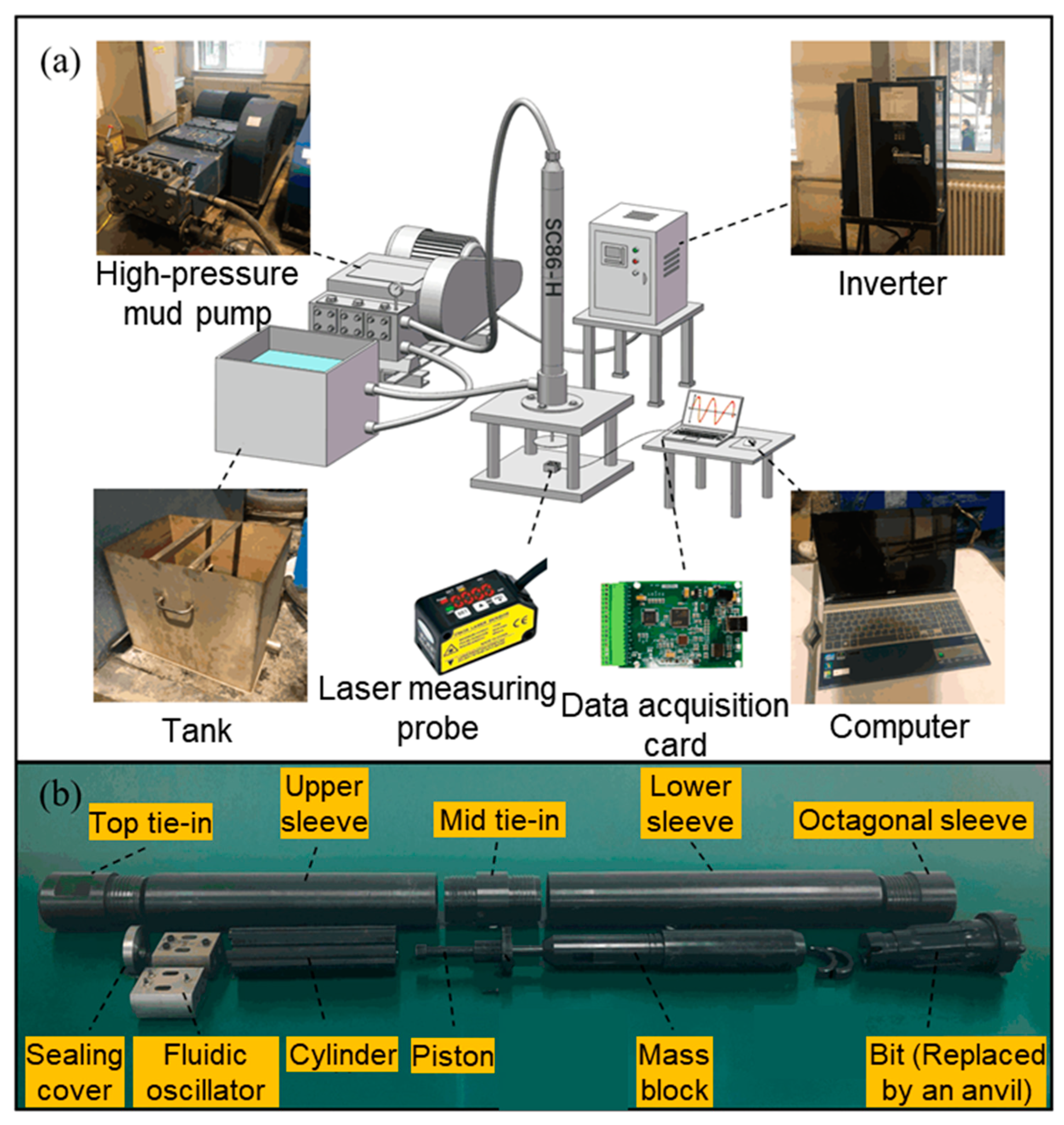
3. Experimental Method
4. Results and Discussions
4.1. Optimal Parameters for Deflector
4.2. Performance Analysis of Fluidic Oscillator with Deflector
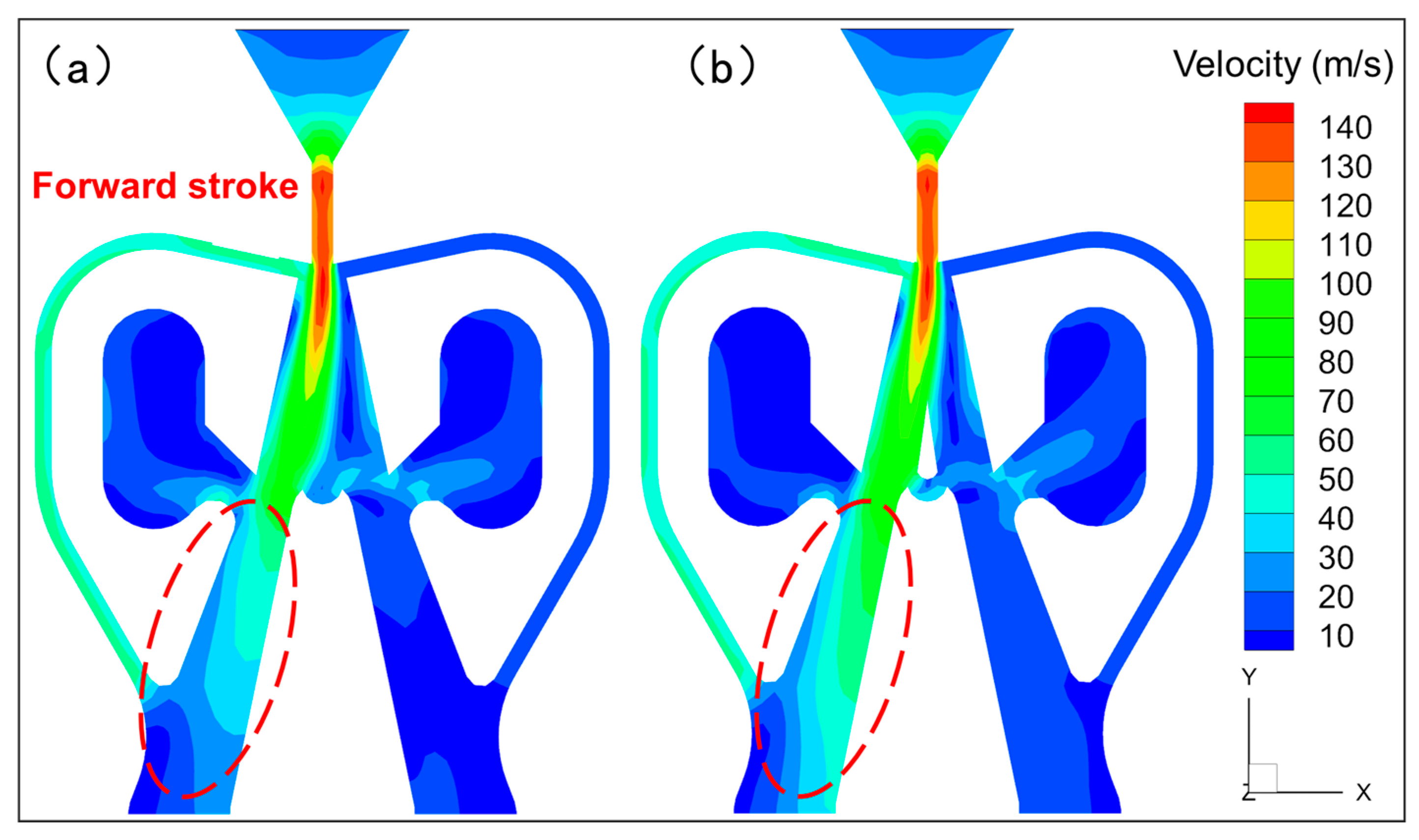
4.2.1. Flow Field Characteristics
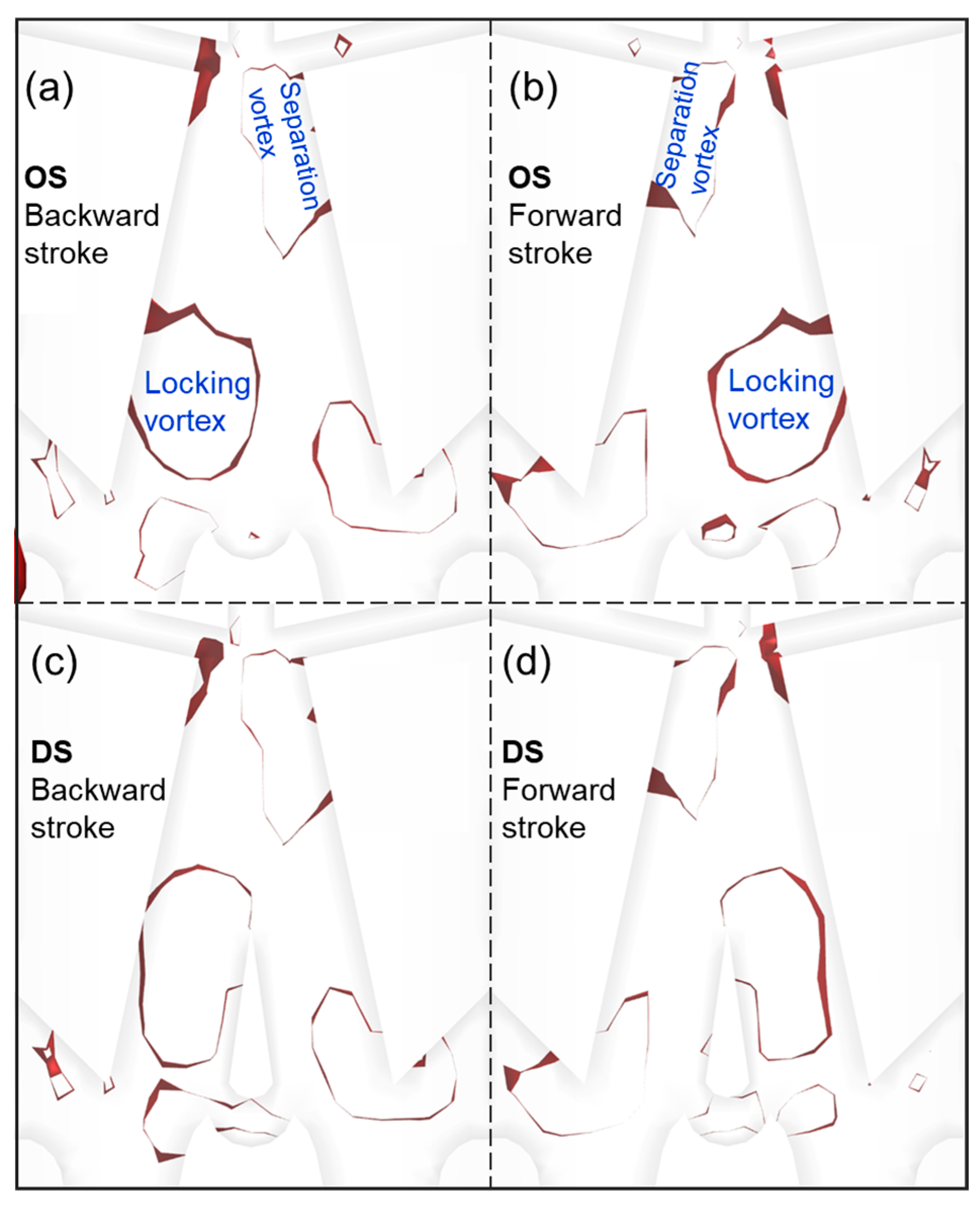
4.2.2. Vortex Characteristics
4.3. Result of the Bench Test
5. Conclusions
- According to the orthogonal test results, the optimal parameter combination for the deflector structure is set at 13.5 mm for the deflector distance, 2.0 mm for the deflector width, and 2.2 mm for the return channel width.
- With the addition of the deflector, the flow rate of the non-attached wall-side evacuation channel in the return and stroke decreased by 9.2% and 5.3%, respectively, indicating that the deflector acts as an obstacle for the main jet to be discharged to the non-attached wall side in both processes, which allows more of the main jet to enter the output channel on the attached wall side.
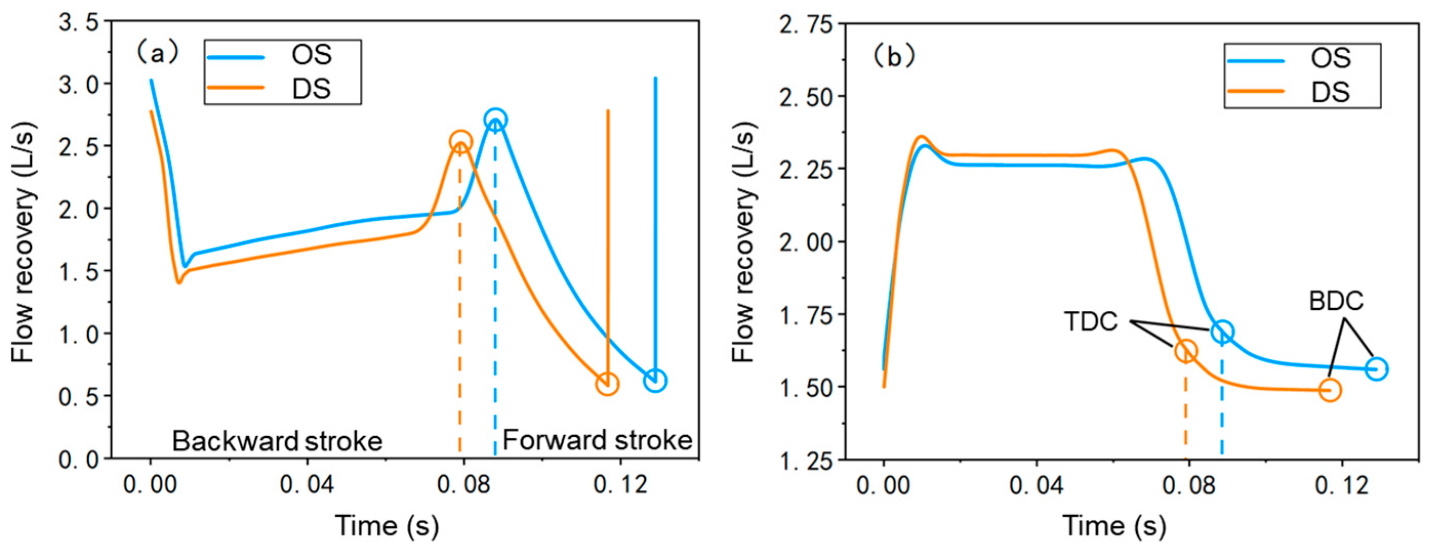
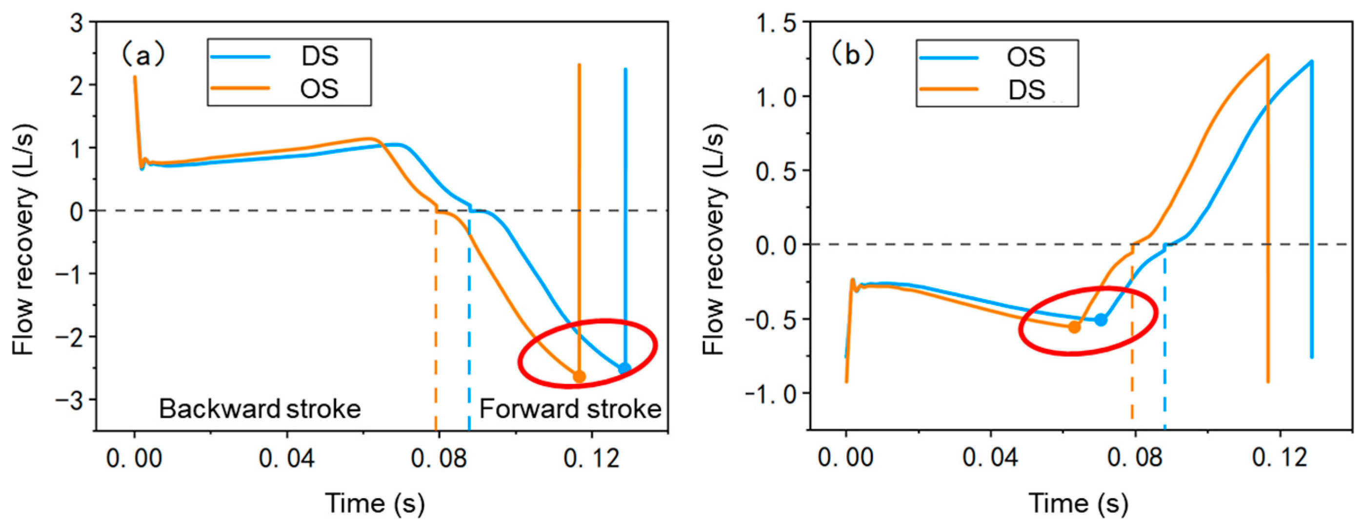
- The maximum flow recovery of the output channel of the deflector structure in the return and stroke increased by 9.1% and 3.6%, respectively, compared with the original structure, indicating that the deflector structure has higher energy utilization.
- The Ω-identification method was used to investigate the effect of the deflector plate structure on the vortices in the cavity. With the addition of the deflector plate structure, the morphology of the separating vortices remains almost unchanged, while the locking vortices were observed to congregate predominantly on a single side of the deflector plate, with an augmented axial reach extending in the upward direction. This redistribution of the locking vortices is instrumental in enhancing the deflection of the primary jet, thereby optimizing the flow field’s stability and efficiency.
- The results of the bench test show that compared with the original structure without the deflector, the average impact frequency of the deflector structure increased by 5.8%, the single average impact energy increased by 7.5%, and the output power increased by 13.75%.
Author Contributions
Funding
Data Availability Statement
Conflicts of Interest
Abbreviations
| BO | Output channel of backward stroke side |
| FO | Output channel of forward stroke side |
| BD | Discharge channel of backward stroke side |
| FD | Discharge channel of forward stroke side |
| TDC | Top dead center |
| BDC | Bottom dead center |
| a | Deflector distance |
| b | Deflector width |
| c | Reflow channel width |
| ρ | Fluid density |
| u,v,w | Components of the velocity vector |
| p | Pressure |
| τ | Viscous stress |
| F | Body force |
| cp | Specific heat capacity |
| k | Heat transfer coefficient |
| ST | Internal energy of the fluid |
| R | Range |
| OS | Original structure |
| DS | Deflector structure |
| A | Symmetric tensor |
| B | Asymmetric tensor |
References
- Sharmin, T.; Khan, N.R.; Akram, M.S.; Ehsan, M.M. A State-of-the-art Review on for Geothermal Energy Extraction, Utilization, and Improvement Strategies: Conventional, Hybridized, and Enhanced Geothermal Systems. Int. J. Thermofluids 2023, 18, 100323. [Google Scholar] [CrossRef]
- Zhang, E.Y.; Wen, D.G.; Wang, G.L.; Yan, W.D.; Wang, W.S.; Ye, C.M.; Li, X.F.; Wang, H.; Tang, X.C.; Weng, W.; et al. The first power generation test of hot dry rock resources exploration and production demonstration project in the Gonghe Basin, Qinghai Province, China. China Geol. 2022, 5, 372–382. [Google Scholar] [CrossRef]
- Li, Y.; Peng, J.; Li, J.; Ge, D. Theoretical and Experimental Study on Single Spherical Button Penetration into Granite Rock Under Dynamic Impact Loading. Rock Mech. Rock Eng. 2022, 55, 213–233. [Google Scholar] [CrossRef]
- Liu, W.; Gao, K. Drilling technical difficulties and solutions in development of Hot dry Rock geothermal energy. Adv. Pet. Explor. Dev. 2017, 13, 63–69. [Google Scholar]
- Lukawski, M.Z.; Anderson, B.J.; Augustine, C.; Capuano, L.E.; Beckers, K.F.; Livesay, B.; Tester, J.W. Cost analysis of oil, gas, and geothermal well drilling. J. Pet. Sci. Eng. 2014, 118, 1–14. [Google Scholar] [CrossRef]
- Yin, K.; Jian, Z.J.; Jiang, R.Q. Research on large impact energy hydro-hammer and its application. Explor. Eng. 1996, 4, 8–10. [Google Scholar]
- Li, Y.; Peng, J.; Zhang, P.; Huang, C. Hard rock fragmentation in percussion drilling considering confining pressure: Insights from an experimental study. Int. J. Rock Mech. Min. Sci. 2021, 148, 104961. [Google Scholar] [CrossRef]
- Li, Y.; Peng, J.; Zhang, Y.; Yin, Q. Rock Indentation Characteristics Induced by Spherical Button Subjected to Dynamic and quasi-static Loads. Rock Mech. Rock Eng. 2023, 56, 5253–5273. [Google Scholar] [CrossRef]
- Peng, J.; Ge, D.; Zhang, X.; Wang, M.; Wu, D. Fluidic DTH hammer with backward-impact-damping design for hard rock drilling. J. Pet. Sci. Eng. 2018, 171, 1077–1083. [Google Scholar] [CrossRef]
- Lourenço, A.M.F.; Miska, S.Z.; Reed, T.D.; Pickell, M.B.; Takach, N.E. Characterization of foam rheology at HPHT for hydraulics optimization whilst drilling underbalanced. Annu. Trans.-Nord. Rheol. Soc. 2003, 11, 39–48. [Google Scholar]
- Zhang, X.; Zhang, S.; Luo, Y.; Wu, D. Experimental study and analysis on a fluidic hammer—An innovative rotary-percussion drilling tool. J. Pet. Sci. Eng. 2019, 173, 362–370. [Google Scholar] [CrossRef]
- Li, K.; Peng, J.; Li, Y.; Ge, D.; Li, J. Performance prediction of solid particle erosion in fluidic oscillators for fluidic hammers based on CFD-DPM. Powder Technol. 2023, 428, 118819. [Google Scholar] [CrossRef]
- Coanda, H. Device for Deflecting a Stream of Elastic Fluid Projected into an Elastic Fluid. U.S. Patent US2052869A, 1 September 1936. [Google Scholar]
- Li, L.; Li, Q.; Ni, Y.; Wang, C.; Tan, Y.; Tan, D. Critical penetrating vibration evo-lution behaviors of the gas-liquid coupled vortex flow. Energy 2024, 292, 130236. [Google Scholar] [CrossRef]
- Li, L.; Xu, W.; Tan, Y.; Yang, Y.; Yang, J.; Tan, D. Fluid-induced vibration evolution mechanism of multiphase free sink vortex and the multi-source vibration sensing method. Mech. Syst. Signal Process. 2023, 189, 110058. [Google Scholar] [CrossRef]
- Karpenko, M.; Stosiak, M.; Šukevičius, Š.; Skačkauskas, P.; Urbanowicz, K.; Deptuła, A. Hydrodynamic Processes in Angular Fitting Connections of a Transport Machine’s Hydraulic Drive. Machines 2023, 11, 355. [Google Scholar] [CrossRef]
- Karpenko, M.; Bogdevičius, M. Investigation of hydrodynamic processes in the system–“pipeline-fittings”. In TRANSBALTICA XI: Transportation Science and Technology, Proceedings of the International Conference TRANSBALTICA, Vilnius, Lithuania, 2–3 May 2019; Springer International Publishing: Cham, Switzerland, 2020; pp. 331–340. [Google Scholar]
- Chen, J.W. Research on Simulation and Experiment of the Liquid Jet Hammer; Jilin University: Changchun, China, 2007. [Google Scholar]
- Pramanik, S.; Das, M.K. Numerical characterization of a planar turbulent offset jet over an oblique wall. Comput. Fluids 2013, 77, 36–55. [Google Scholar] [CrossRef]
- Zhang, T.; Qin, Y.; Han, D. A Canyon Street Optimization Design Method Based on Pollutant Concentration Control. C.N. Patent CN113378494A, 10 September 2021. [Google Scholar]
- Ge, D.; Peng, J.; Li, K.; Huang, C.; Lian, M.; Yang, Z. Influence of water-based drilling fluids on the performance of the fluidic down-the-hole hammer. J. Pet. Sci. Eng. 2020, 195, 107817. [Google Scholar] [CrossRef]
- Zhang, G.; Peng, J.; Ge, D.; Li, J.; Li, B.; Xie, Y. Effect of control flow on main jet switching for single and double feedback channels fluidic oscillator. J. Pet. Sci. Eng. 2022, 216, 110810. [Google Scholar] [CrossRef]
- Hunt, J.C.; Wray, A.A.; Moin, P. Eddies, streams, and convergence zones in turbulent flows. In Center for Turbulence Rersearch Proceeding8 of the Summer Program; NASA: Washington, DC, USA, 1988; pp. 193–208. [Google Scholar]
- Liu, C. Liutex-third generation of vortex definition and identification methods. Acta Aerodyn. Sin. 2020, 38, 413–431. [Google Scholar]


| Levels | Factors | ||
|---|---|---|---|
| a (mm) | b (mm) | c (mm) | |
| 1 | 12.5 | 1.6 | 1.8 |
| 2 | 13.5 | 2.0 | 2.2 |
| 3 | 14.5 | 2.4 | 2.6 |
| Experiment No. | Input | Output | ||||
|---|---|---|---|---|---|---|
| a (mm) | b (mm) | c (mm) | Error | Cycle Time (s) | Impact Velocity (m/s) | |
| 1 | 1 | 1 | 1 | 1 | 0.1198 | 5.33 |
| 2 | 1 | 2 | 2 | 2 | 0.1188 | 5.36 |
| 3 | 1 | 3 | 3 | 3 | 0.1278 | 5.32 |
| 4 | 2 | 1 | 2 | 3 | 0.1178 | 5.38 |
| 5 | 2 | 2 | 3 | 1 | 0.1128 | 5.38 |
| 6 | 2 | 3 | 1 | 2 | 0.1258 | 5.34 |
| 7 | 3 | 1 | 3 | 2 | 0.1198 | 5.32 |
| 8 | 3 | 2 | 1 | 3 | 0.1196 | 5.31 |
| 9 | 3 | 3 | 2 | 1 | 0.1276 | 5.32 |
| Cycle time | ||||||
| K1 | 0.1221 | 0.1191 | 0.1217 | 0.1219 | ||
| K2 | 0.1206 | 0.1189 | 0.1214 | 0.1215 | ||
| K3 | 0.1223 | 0.1271 | 0.1219 | 0.1217 | ||
| R | 0.0017 | 0.0082 | 0.0005 | 0.0004 | ||
| Factors ordered by significance | b > a > c | |||||
| Best combination | a2b2c2 | |||||
| Impact velocity | ||||||
| K1 | 5.3367 | 5.3433 | 5.3267 | 5.3433 | ||
| K2 | 5.3667 | 5.3500 | 5.3533 | 5.3400 | ||
| K3 | 5.3167 | 5.3267 | 5.3400 | 5.3367 | ||
| R | 0.0500 | 0.0233 | 0.0267 | 0.0033 | ||
| Factors ordered by significance | a > c > b | |||||
| Best combination | a2b2c2 | |||||
| Factors | Sum of the Squares of Deviations | Degrees of Freedom | Mean Square | F Ratio | P Ratio | Significance |
|---|---|---|---|---|---|---|
| a | 5.40 × 10⁻⁶ | 2 | 2.70 × 10⁻⁶ | 21.7 | 0.044 | ** |
| b | 1.30 × 10⁻⁴ | 2 | 6.51 × 10⁻⁵ | 523 | 0.002 | *** |
| c | 4.36 × 10⁻⁷ | 2 | 2.18 × 10⁻⁷ | 1.75 | 0.3636 | |
| Total error | 2.49 × 10⁻⁷ | 2 | 1.24 × 10⁻⁷ |
| Factors | Sum of the Squares of Deviations | Degrees of Freedom | Mean Square | F Ratio | P Ratio | Significance |
|---|---|---|---|---|---|---|
| a | 3.8 × 10⁻³ | 2 | 1.90 × 10⁻³ | 57 | 0.017 | ** |
| b | 8.67 × 10⁻⁴ | 2 | 4.33 × 10⁻⁴ | 13 | 0.071 | * |
| c | 1.07 × 10⁻³ | 2 | 5.33 × 10⁻⁴ | 16 | 0.059 | * |
| Total error | 6.67 × 10⁻⁵ | 2 | 3.33 × 10⁻⁵ |
Disclaimer/Publisher’s Note: The statements, opinions and data contained in all publications are solely those of the individual author(s) and contributor(s) and not of MDPI and/or the editor(s). MDPI and/or the editor(s) disclaim responsibility for any injury to people or property resulting from any ideas, methods, instructions or products referred to in the content. |
© 2025 by the authors. Licensee MDPI, Basel, Switzerland. This article is an open access article distributed under the terms and conditions of the Creative Commons Attribution (CC BY) license (https://creativecommons.org/licenses/by/4.0/).
Share and Cite
Li, J.; Peng, J.; Ge, D.; Zhang, G. Simulation and Experimental Research on a Fluidic Oscillator with a Deflector Structure. Energies 2025, 18, 1336. https://doi.org/10.3390/en18061336
Li J, Peng J, Ge D, Zhang G. Simulation and Experimental Research on a Fluidic Oscillator with a Deflector Structure. Energies. 2025; 18(6):1336. https://doi.org/10.3390/en18061336
Chicago/Turabian StyleLi, Jiming, Jianming Peng, Dong Ge, and Guang Zhang. 2025. "Simulation and Experimental Research on a Fluidic Oscillator with a Deflector Structure" Energies 18, no. 6: 1336. https://doi.org/10.3390/en18061336
APA StyleLi, J., Peng, J., Ge, D., & Zhang, G. (2025). Simulation and Experimental Research on a Fluidic Oscillator with a Deflector Structure. Energies, 18(6), 1336. https://doi.org/10.3390/en18061336