Article

Research on the Mechanism of Thermal Power of an Interior Permanent Magnet Eddy Current Heater Driven by Wind

School of Energy and Power Engineering, Northeast Electric Power University, Jilin 132000, China
*
Author to whom correspondence should be addressed.
Energies 2025, 18(4), 932; https://doi.org/10.3390/en18040932
Submission received: 15 January 2025 / Revised: 6 February 2025 / Accepted: 11 February 2025 / Published: 14 February 2025
(This article belongs to the Section J: Thermal Management)

Abstract

:
The interior permanent magnet eddy current heater (IPMECH) is a new type of energy conversion device with zero emissions, no pollution, and high efficiency, which has attracted widespread attention. In this paper, a combined numerical simulation and experimental method is used to study the effect of stator structure on the magnetic flux density (MFD) distribution and thermal power of an IPMECH, and the mechanism of thermal power enhancement is revealed. The article aims to provide theoretical and practical support for heater thermal power enhancement. The results show that compared with a solid IPMECH, both closed-slot and open-slot IPMECHs can improve the stator MFD and thermal power, and the stator static MFD amplitudes of closed-slot and open-slot IPMECHs with 16 3 mm copper strips are 1.340 and 1.607 T, respectively. The thermal power growth rate (TPGR) and electromagnetic torque growth rate (ETGR) of the closed-slot IPMECH with 16 3 mm copper strips at 200 rpm are 80.46% and 78.22% respectively, while those of the open-slot IPMECH are 119.10% and 117.17%, respectively. At 200 rpm, the TPGRs of the closed-slot and open-slot prototype with sixteen copper strips are 35.24% and 61.09%, respectively. The experimental results verify the accuracy and reliability of the simulation results. The research work in this paper provides theoretical support and practical proof for further IPMECH optimization.

1. Introduction

At the 28th Conference of the Parties (COP28) in Dubai, nearly 200 governments agreed that global renewable energy use needs to triple by 2030, demonstrating the determination of governments to move away from fossil fuels, limit the rise in global temperatures, and avert climate change [1,2]. Around 40% of households globally require space heating for part of the year, making winter heating and sanitary hot water essential energy services. Space heating and water heating account for almost half of global energy consumption in buildings [3]. Nearly two-thirds of heating energy comes from fossil fuels, which have the disadvantages of being non-renewable, polluting the environment, and producing greenhouse gases [4]. Therefore, energy policies around the world encourage and utilize renewable energy sources such as wind, water, geothermal, and solar energy for space heating [5].
Wind energy is a resourceful, safe, zero-emission, renewable green energy source [6,7,8]. Currently, wind power heating (“wind to power to heat”) is used to reduce carbon emissions from space heating [9,10,11,12,13]. This method is not economical, because not only are expensive generators, rectifiers, and inverters needed, but the equipment is complex, and the efficiency of wind power heating is lower than that of wind to heat [14,15,16,17]. There are a number of methods for the direct conversion of wind to heat, including friction [18,19], compression [20,21], and magnetic eddy currents [22,23]. Magnetic eddy current heating has the potential to generate high-temperature heat compared to other methods, and the lack of physical contact with magnetic eddy current heaters reduces maintenance and part replacement costs [24]. Therefore, permanent magnet eddy current heating by wind has attracted a widespread attention [25,26,27,28].
For effective wind to heat, the design, optimization, and operational characterization of magnetic eddy current heaters are of critical importance. Domestic and foreign scholars’ research on permanent magnet eddy current thermogenesis mainly focuses on the following aspects: (1) Mathematical modeling of the heaters. Hai D. [29,30,31] established a mathematical model of heater loss based on electromagnetic theory combined with the distribution characteristics of the induced current and skin effect. Shukang C. [32] established a mathematical model of flameless heater hysteresis, eddy current, and short-circuit power based on the motor temperature rise inverse problem. Chu J. [33] established a mathematical theoretical model of thermal power and a thermal circuit model of a food heater based on electromagnetic fields and empirical formulas. Honglei L. [34] considered the influence of the skinning effect on eddy current distribution based on Coulomb’s law, Maxwell’s equations, and the Lorentz force law. An equivalent magnetic circuit model was developed to derive mathematical analytical expressions for the air gap magnetic flux density (AMFD), torque, and thermal power of the heater. (2) Optimization of heaters. Both heaters and motors are based on Maxwell’s theory and electromagnetic field theory, and there is currently a huge difference in their optimization. These research studies mainly focus on the comprehensive optimization of motor efficiency and electromagnetic performance using different multi-objective optimization methods [35,36,37]. However, the optimization of heaters is mostly focused on construction and materials. T. Tudorache [38] analyzed the influence of stator wall material and wall thickness, the number of poles, air gap thickness, and permanent magnet geometric parameters on the performance of the heater, and optimized the design of the heater. V. Fireeanu [39] determined the optimum value of the stator wall thickness based on a 2D electromagnetic field finite element model. Jiaxin Y. [40] simulated and analyzed a permanent magnet eddy current heater and investigated the effects of stator slot type, the number of stator slots, and stator thickness on the heating power. The total heat generated by the optimized model is 84.23% higher than that before optimization, and the efficiency of the device is increased by 23.77%. I. Dirba [41] carried out a finite element analysis of a heater and found that the stator body should be made from a highly conductive material and the permanent magnet body should be made from a highly permeable material, like NdFeB material. Sina Hadadi [25] optimized the magnet configuration and the number of poles to increase the power efficiency of the actuator. The optimized heater achieves excellent performance at lower wind speeds and rotational speeds. Honglei L. [42] used numerical simulation to investigate the combined effects of stator structure and material on the thermal power of the heater. The results show that the stator material has higher permeability, thermal power, and torque, and the proportion of high harmonics is lower, which is conducive to reducing the radial vibration of the heater; reducing the length of the air gap is conducive to increasing the thermal power, but it also increases the harmonics, and when designing the heater, the higher the rotational speed is, the smaller the stator wall thickness should be. (3) Operational characteristics of the heater. A. Khanjari [43,44] showed that the energy efficiency of permanent magnet eddy current heaters exceeds 95% at different speeds. I. Sobor [45] derived a semi-empirical formula for the thermal power, which is proportional to 1.5 times the rotational speed and has a thermal efficiency of more than 90%. Xiaohong L. [28] verified the influence of factors such as rotational speed and the clearance between the turntable and the heating plate on the temperature rise of the heating plate. Through regression analysis, an empirical equation was derived to provide guidance for further development of the heating system. O. Nebi [46] studied the correlation between the input and output operating parameters of the heater by considering the temperature dependence and magnetic nonlinearity of the physical properties of the heater. (4) The system of permanent magnet eddy current heating driven by wind. T. Tudorache [47] investigates the dynamic response of wind to heat systems. Sina Hadadi [25] developed a new eddy current water heating system that utilizes wind energy for efficient heating, with an energy efficiency of more than 90% and a facility utilization rate of 10.34%, results that highlight the potential of thermogenic systems as an efficient and sustainable heating solution for areas with similar wind conditions.
The above scholars focus on researching surface-mounted permanent magnet eddy current heaters, as there is a risk of demagnetization in permanent magnets [38,48]. The stator is made of a single material, meaning it struggles to have excellent conductivity and magnetic permeability at the same time. The interior permanent magnet rotor structure has reluctance torque, which can more easily achieve high power and torque density. A permanent magnet is embedded in the rotor core, which is not easy to demagnetize and has high reliability [49,50]. Some papers only focus on optimizing the torque–speed characteristics of wind turbines without addressing the mechanisms behind heat generation, and the stator structure’s influence on the electromagnetic field distribution and the thermogenic power need to be explored in depth. Based on the above analysis, this paper focuses on the design of the stator structure of an interior permanent magnet eddy current heater (IPMECH), the AMFD and stator magnetic flux density (MFD) distribution, the thermal power, and the electromagnetic torque, and verifies the accuracy of the numerical simulation through experiments.
The purpose of this paper is to explore the influence mechanism of stator structure on the air gap magnetic density, stator magnetic density distribution of thermal power, and electromagnetic torque, to provide certain theoretical support for the further enhancement of heater power density and heater design. In addition, this paper proposes a closed-slot heater and an open-slot heater, and investigates the effects of the number of copper strips and the size of the copper strips on the air gap magnetization and stator magnetization distribution through numerical simulation methods. The mechanism of air gap density and stator density distribution on the thermal power and electromagnetic torque is analyzed. In this paper, the mathematical model of the heat generator, numerical simulation independence verification, and experimental procedure are given in Section 2. The AMFD and stator MFD distributions of different structural heat generators are analyzed in Section 3.1. The thermal power and electromagnetic torque of different structural heaters are simulated and analyzed in Section 3.2. The prototype’s thermogenic power is experimentally explored in Section 3.3. The conclusion is then given in Section 4, and the main contributions of this paper are summarized as follows:
  • Different structures models of IPMECHs are established, and the formulas for calculating the electromagnetic field, thermal power, and electromagnetic torque of IPMECHs are derived;
  • The characteristics of air gap and stator MFD distributions are analyzed for different structural IPMECHs, as well as the effects of the quantity and size of copper strips on the MFD distribution;
  • The effect of the quantity and size of copper strips on the thermal power and electromagnetic torque of open/closed slots is analyzed using the finite element method;
  • The operating characteristics of closed-slot and open-slot heater prototypes are experimentally explored and the accuracy and reliability of the simulation results are verified.

2. Methods and Experimental

2.1. IPMECH

The IPMECH is a new type of energy conversion device that can utilize other energy sources such as wind energy, water energy, etc. The heater is driven by the prime mover to efficiently convert other forms of energy into thermal energy to heat the fluid. It can be used as heating equipment for residential and large buildings and in agriculture. The IPMECH is shown in Figure 1. It is mainly composed of a rotor, stator, housing, and spiral fluid channel. Permanent magnets are embedded in the rotor with parallel magnetization. To improve the dynamic stability of the rotor, the rotor is made of cast aluminum and bolted. There is a spiral fluid channel inside the stator that is connected to the external circulation pipeline. The wind turbine drives the shaft of the IPMECH to rotate, which rotates the permanent magnet mounted on the spindle and establishes a rotating magnetic field. It utilizes the induced current, hysteresis, and eddy current heat effect produced on the stator wall to efficiently convert wind energy into thermal energy. The thermal power generated in the IPMECH is collected and used by the circulation of the fluid medium.
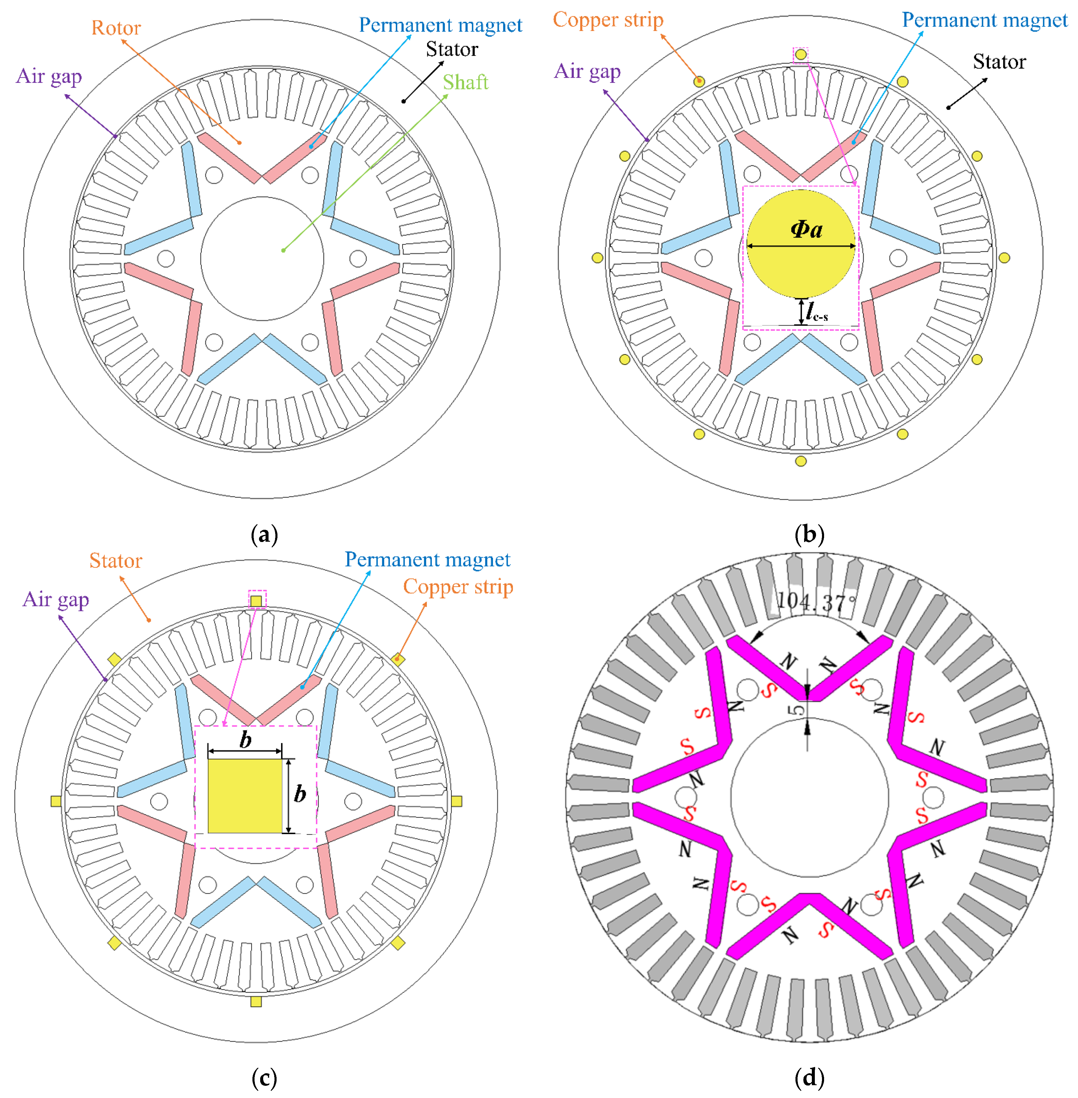
Figure 2 shows the IPMECH model and magnetization direction. According to the different stator structures of the heater, it can be divided into three types. (1) Solid IPMECH. As shown in Figure 2a, the heater uses a single stator material, and this type of stator with a solid structure is called a solid IPMECH. (2) Closed-slot IPMECH. After drilling holes in the stator core of the heater, several copper strips are embedded, and a short-circuit ring is used to short-circuit the copper strips at the end, which is similar to the structure of the closed slot in the motor; this is called a closed-slot heater. As shown in Figure 2b, the diameter of the copper strip is Φ a , and the distance from the inner edge of the stator is l c - s . (3) Open-slot IPMECH. In an open-slot IPMECH, slots are made in the inner circle of the stator, and a copper strip is placed in the slots and closely attached to the inner circle of the stator. The stator structure is as shown in Figure 2c; the width and height of the copper strip are both “b”. The magnet is placed in the V-shaped slot of the rotor, and the position and magnetization direction of the permanent magnet are shown in Figure 2d. The stator and rotor are placed coaxially, and both the stator and rotor materials are made of Steel-1010. The permanent magnet material is NdFeB35, and the copper strip material is copper. The physical properties of the material are shown in Table 1.

2.2. Theoretical Model

Electricity and magnetism are an inseparable organic entity. The theoretical basis of all electromagnetic field analysis is Maxwell’s equations. The IPMECH operates at low frequency, the electric field changes little with time, and the displacement current can be neglected compared with the conduction current. In addition, there usually is no free charge in the field, so Maxwell’s equations are as follows [51,52]:
  • Ampere–Maxwell law:
    × H = J
  • Gauss’s law for magnetism:
    B = 0
  • Faraday’s law of induction:
    × E = B t
  • Gauss’s law:
D = ρ = 0
where H is the magnetic field intensity; J is the current density; D is the displacement flux density; B is the magnetic flux density (MFD); E is the electric field; and ρ is the charge density.
To solve the above equations, we need to add three independent vector equations:
D = ε E
B = μ H
J = σ E
where ε is the permittivity; μ is the magnetic permeability; and σ is the conductivity.
Based on Gauss’s law for magnetism and Faraday’s law of induction, a scalar potential φ and vector potential A are introduced. To ensure the uniqueness of the vector potential A , the Coulomb gauge A = 0 is introduced. The field quantities at each point in the calculation domain are as follows [53]:
B = × A
E = φ A t = φ ω A θ
ω = 2 π n p / 60
where ω is the angular velocity of magnetic field variation, θ is the phase angle of the solution point, n is the rotational speed, and p is the number of pole pairs.
The distribution of magnetic field intensity and magnetic induction intensity inside the stator is as follows:
H x y , t = H m e b y e j ω t b y
B x y , t = μ 0 μ r H m e b y e j ω t b y
b = μ 0 μ r σ ω 2
where H m is the amplitude of external magnetic field strength, and μ 0 and μ r are the vacuum permeability and relative permeability, respectively.
The boundary conditions for the stator magnetic field are as follows:
H x | y = 0 = H z | y = 0 ,   H y | y = 0 = H m e j ω t
The eddy current J s , the electromagnetic torque F , and the thermal power P in the stator are, respectively,
J s = H x y = b ( 1 + j ) H m e b y e j ( ω t b y )
F = V σ ( E + v × B ) d V
P = F v = V σ ( E + v × B ) v d V

2.3. Independence Verification

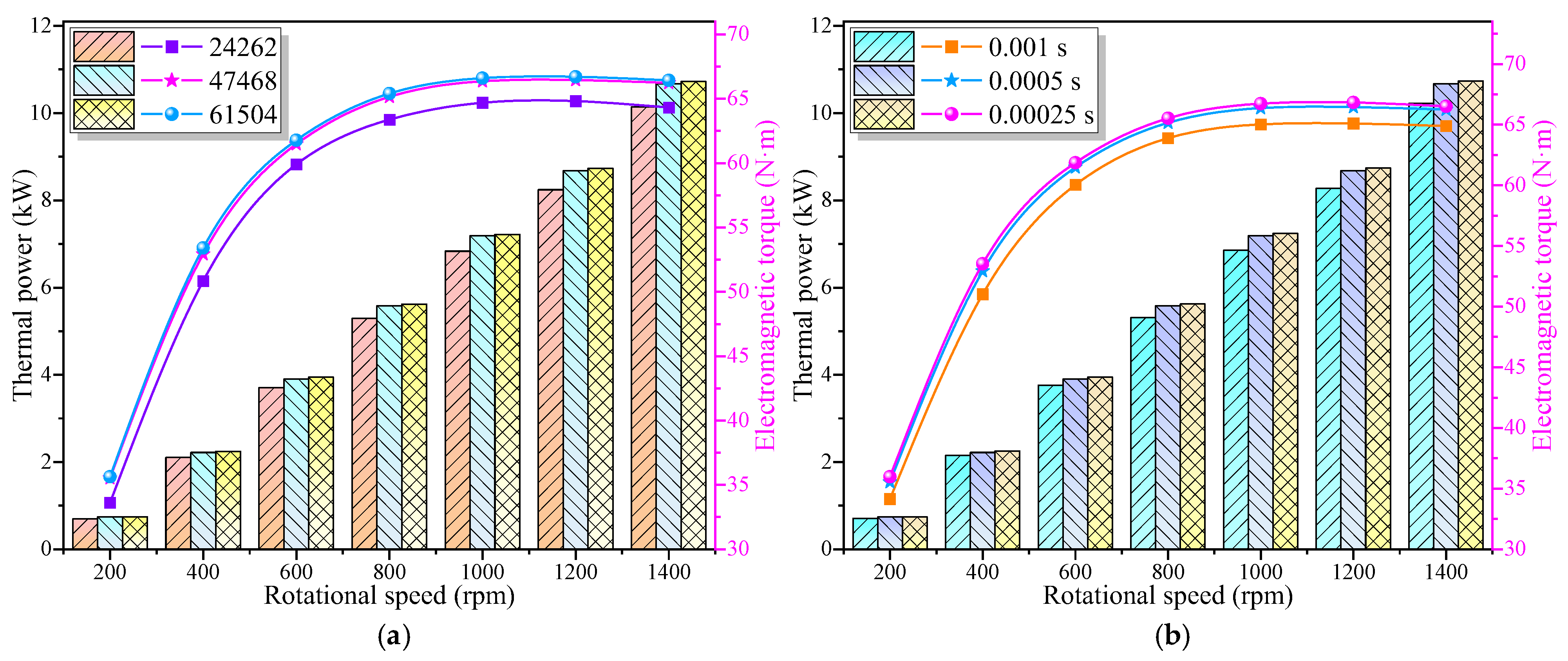
In the numerical simulation of this paper, the axial length of the IPMECH is 175 mm. The structural parameters of the IPMECH are shown in Table 2. For fair comparison, the rotor of the IPMECH remains unchanged, and the temperature of each component is 22 °C. Simulations were carried out using the Maxwell 2D module in the commercial software Ansys Electronics Desktop 17.1, with a vector potential boundary of 0 weber/m as the boundary condition. To ensure calculation accuracy and improve calculation speed, independence verification was conducted on the grid size and time step size. The changes in thermal power and electromagnetic torque were tested under different grid numbers and time steps. The calculation results are shown in Figure 3. By comparison, this paper selected 47,468 grids and a time step of 0.0005 s for simulation analysis.

2.4. Experimental

2.4.1. Experimental Setup

IPMECHs should generally be driven by a wind turbine, but due to the instability of wind energy, the power output of wind turbines is unstable. In order to more accurately explore the operating characteristics of the IPMECH, a variable-frequency speed-regulating three-phase asynchronous motor was used in the wind magnetic eddy current heating system to simulate the output characteristics of the heater at different wind speeds. The schematic diagram of the experimental system is shown in Figure 4a. The main experimental equipment includes the variable-frequency speed regulation three-phase asynchronous motor, the IPMECH, and a water tank. In addition, it also includes a frequency converter for controlling the frequency conversion motor, a control cabinet for controlling the entire system, a thermometer, a flowmeter, a pressure gauge, an expansion water tank, and a data acquisition unit for collecting test data. The experimental platform is shown in Figure 4b. Import and export thermometers are calibrated on the lab bench with high-precision thermometers and then used. The parameters of the prototype of the IPMECH are shown in Table 3.

2.4.2. Experimental Procedure

This paper developed one solid prototype, one closed-slot prototype, and one open-slot prototype. The closed-slot and open-slot prototypes reserved 16 holes for placing copper strips. In the experiment, 4, 8, 12, and 16 copper strips were symmetrically placed, and Steel-1010 strips with the same size were reserved for other holes. The experiment was conducted indoors at a temperature of 23 °C, with an initial circulating water temperature of 19.7 °C. The rotational speed of the three-phase asynchronous motor was controlled by a frequency converter. Experiments were conducted at seven different rotational speeds (200, 400, 600, 800, 1000, 1200, and 1400 rpm) in different structures of prototypes. After checking that the test requirements are met, the power supply of the control cabinet is started, the circulating pump is turned on, circulating water is supplied to the heater, the data acquisition system is operated, and then the parameters of the frequency converter are adjusted to enable the motor to reach the required speed for the test. After the temperature measurement points at the inlet, outlet, and the housing of the heater are the same, and the flow meter shows stable flow, the motor is started by the frequency converter to start the test, and the test data are recorded through the data acquisition system. The output thermal power of the IPMECH is calculated based on the water quality and the changes in water temperature (Equation (18)).
P e = c w m w ( T e T 0 ) t e
where P e is the thermal power of the IPMECH, c w is the specific heat capacity of water, m w is the quality of water in the experiment, T e is the water temperature in the water tank at the end of the experiment, T 0 is the water temperature in the water tank at the beginning of the experiment, and t e is the operating time of the IPMECH.

2.4.3. Analysis of Uncertainty

Uncertainty analysis is an important part of the experimental process, which can effectively improve the reliability of the experiment. Due to instrument selection, experimental environmental conditions, manual observation, and the measurement of readings (data acquisition unit), uncertainty will occur. The parameters of the measurement equipment are shown in Table 4. This paper is based on the uncertainty analysis method of the American Academy of Aeronautics and Astronautics. A coverage factor k = 2 was chosen, providing a confidence level of approximately 95%. The relative uncertainty at different speeds is detailed in Appendix A. The experimental results have a certain degree of fluctuation, and the average of six independent experiments is taken as the experimental result in this paper.

3. Results and Discussion

3.1. Electromagnetic Field Characteristics of IPMECH

The stator and rotor are two important components of an IPMECH, which are magnetically coupled and achieve energy conversion between them through a magnetic field. The MFD distribution reflects the magnetic field strength and distribution of the heater. By analyzing the MFD distribution, it is possible to understand whether the magnetic circuit design of the heater is reasonable and further optimize the heater.
Figure 5 shows the flux distribution of IPMECHs with different structures. When the heater is stationary (i.e., t = 0 s), the flux generated by the permanent magnet is symmetrically distributed in the heater. From the figure, it can be seen that the flux in the stator is mainly distributed on the inner surface. Copper belongs to non-magnetic materials with low magnetic permeability. Compared with the solid structure, the density of flux in the copper strip area of the closed-slot and open-slot structures is smaller, and the surrounding flux of the copper strips is squeezed. When the rotor of the heater rotates stably (i.e., at t = 0.5 s), the interaction between the cross-axis magnetic field and the main magnetic field in the stator produces a demagnetization effect on one side of its rotation direction and a demagnetization effect in the opposite direction. The presence of copper strips in the closed-slot and open-slot heaters increases the tangential magnetic resistance of the stator, resulting in deeper penetration of flux in the nearby area.
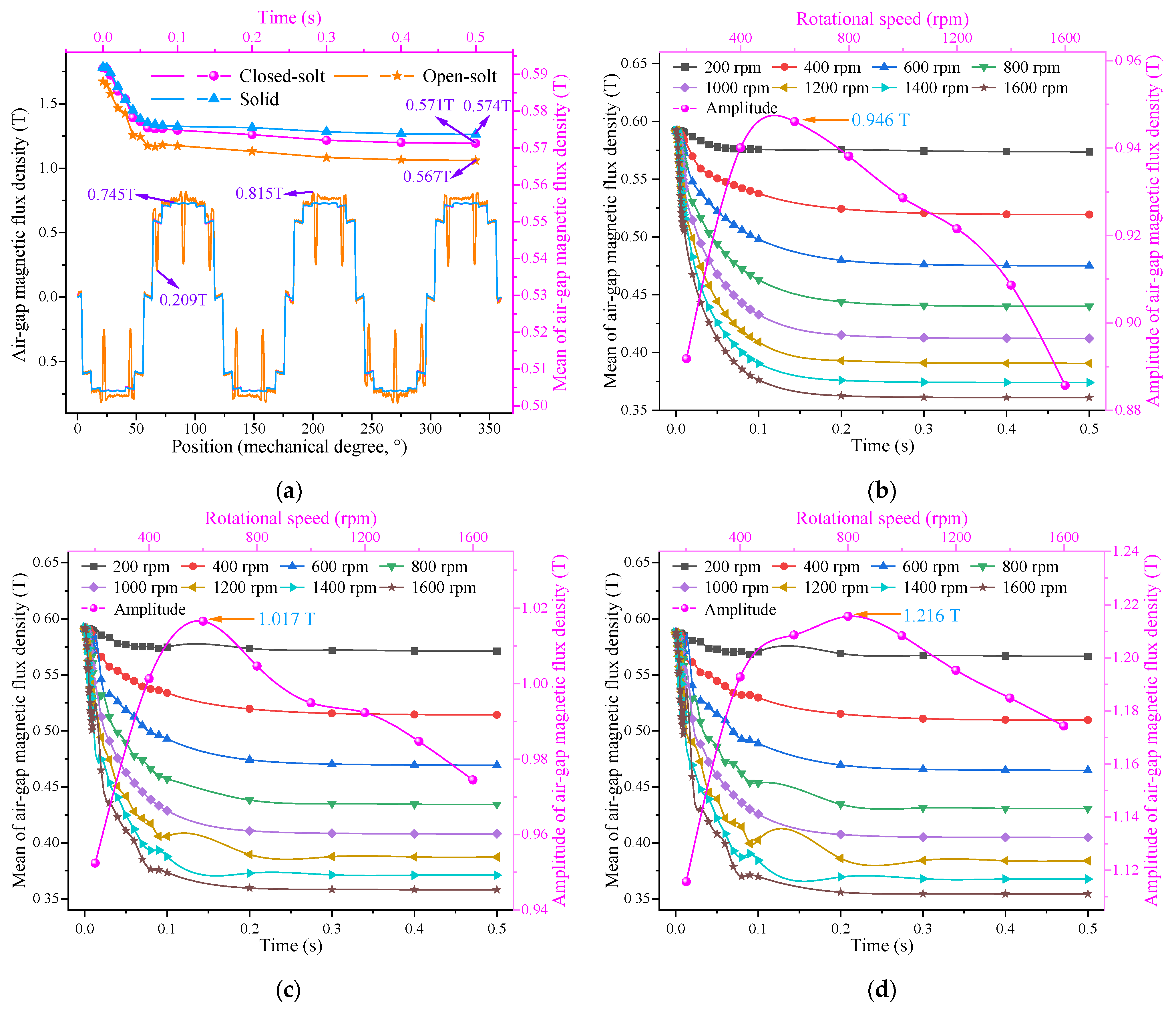
AMFD refers to the distribution of MFD within the air gap region, which reflects the strength and uniformity of the magnetic field. The AMFD is both a function of space and time. Figure 6a shows the AMFD at different positions and times. It can be seen from the figure that the static AMFD at different positions is a flat-topped waveform, and it varies periodically in space. The static AMFD of solid and closed-slot IPMECHs at different positions is almost identical, with an amplitude of 0.745 T. The copper strips of the closed-slot IPMECH are located at a certain depth from the inner edge of the stator. Although the magnetic resistance is high near the copper strips, and it can affect the MFD distribution inside the stator, it has almost no effect on the AMFD. Compared with solid and closed-slot, the open-slot heater has a larger fluctuation in static air gap magnetic density at the location of the copper strip, with a maximum value of 0.815 T and a minimum value of 0.209 T, respectively. The copper strips of the open-slot heater are located at the inner edge of the stator, where the magnetic permeability of copper is low and the magnetic resistance is high near the copper strips, resulting in a lower MFD. After the rotor of the heater rotates, the armature effect generated by eddy currents in the stator increases the magnetic resistance inside the stator. Therefore, the mean of AMFD of different structured heaters shows a decreasing trend over time and stabilizes after a period of time. The mean of air gap magnetic density of solid steel heaters is the highest, followed by closed-slot heaters, and open-slot heaters are the lowest. When the rotational speed and time are 200 rpm and 0.5 s, respectively, the means of air gap magnetic flux densities of the solid, closed-slot, and open-slot heaters are 0.574, 0.571, and 0.567T, respectively. Figure 6b–d show the mean values and amplitudes of AMFD for solid, closed-slot, and open-slot IPMECHs at different rotational speeds, respectively. From the figure, it can be seen that as the rotational speed increases, the stator armature effect becomes stronger, and the mean of the AMFD decreases with the increase in rotational speed. The mean of AMFD of the solid IPMECH steadily decreases over time and gradually stabilizes. For the closed-slot and open-slot IPMECHs, the presence of copper strips causes an uneven distribution of stator magnetic resistance in space, resulting in a decreasing trend in AMFD over time and eventually stabilizing, with fluctuations during the decrease. The amplitude of air gap magnetic flux densities in solid, closed-slot, and open-slot IPMECHs show an increasing and then decreasing trend with the increase in rotational speed, reaching maximum values of 0.946, 1.017, and 1.216 T at 600, 600, and 800 rpm, respectively.
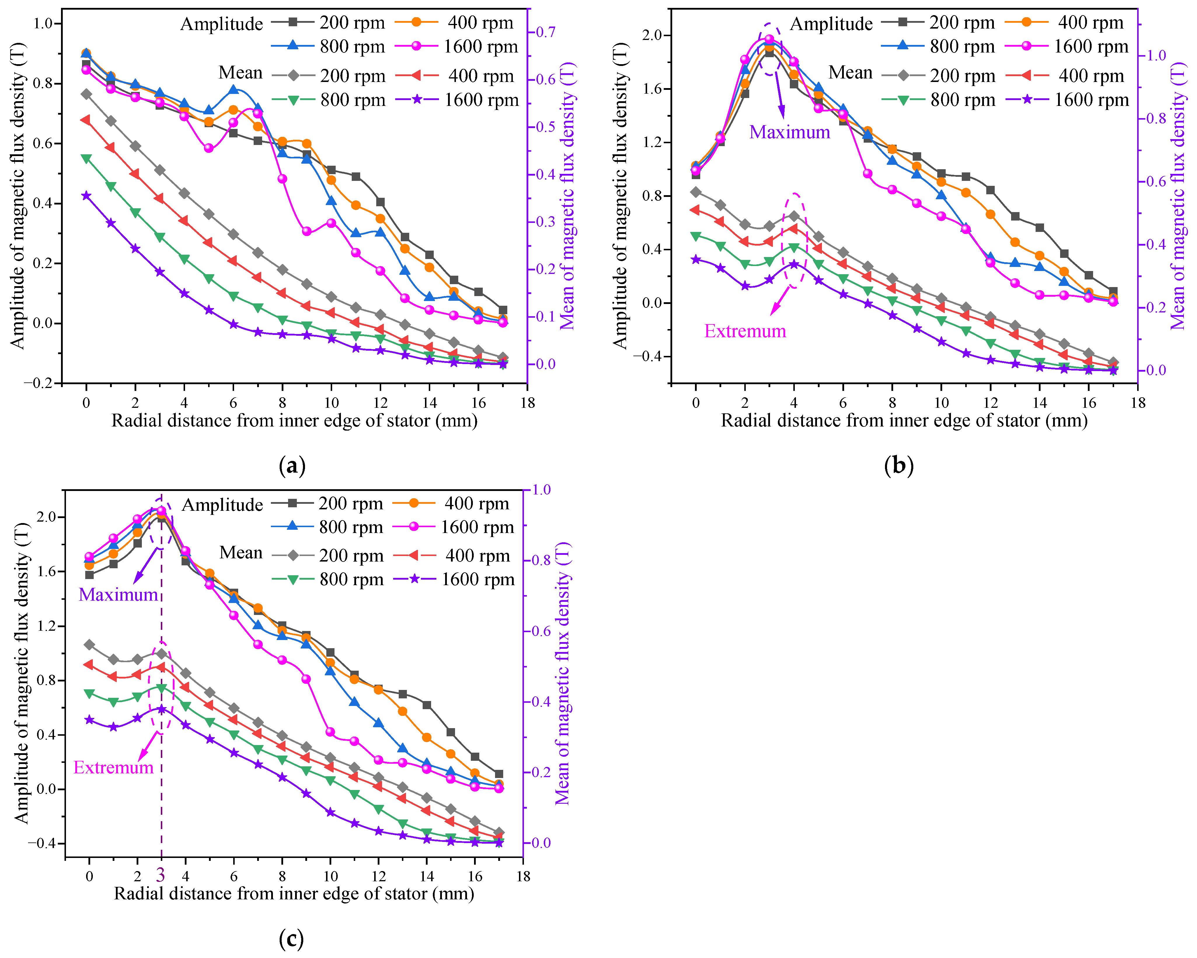
Figure 7 shows the amplitudes and mean values of the MFD along the radial direction in the stator at different rotational speeds. It can be observed that the mean value of the MFD decreases with increasing rotational speed in different structures of the heater stator due to the demagnetizing effect of the armature magnetic field in the stator, and this effect is more obvious with increasing rotational speed. The mean value of the MFD in the stator of the solid IPMECH shows a decreasing trend along the radial direction, and the decrease is more drastic at higher speeds. There exist extreme points of the stator MFD amplitude in the radial direction in solid IPMECHs, the main reason for which is the MFD being superimposed at different times. Due to the skin effect, eddy currents are concentrated within a certain range on the surface of the stator, and the presence of copper strips increases the tangential reluctance in the stator, which causes the highly saturated region of the flux to be shifted along the radial direction. The mean value of stator MFD in closed-slot and open-slot IPMECHs shows a decreasing, then increasing, and then decreasing trend along the radial direction, and reaches the extreme value at 4 and 3 mm from the inner edge of the stator, respectively, which is the deepest position of the copper strip from the inner edge of the stator in the radial direction, and there is no additional tangential reluctance influence at this position, resulting in an increase in the MFD, and thus the extreme point is obtained here. The amplitudes of the MFD in the stator of the closed-slot and open-slot IPMECHs show a tendency to increase and then decrease in the radial direction, and the larger the rotational speed, the more significant the increase and decrease.
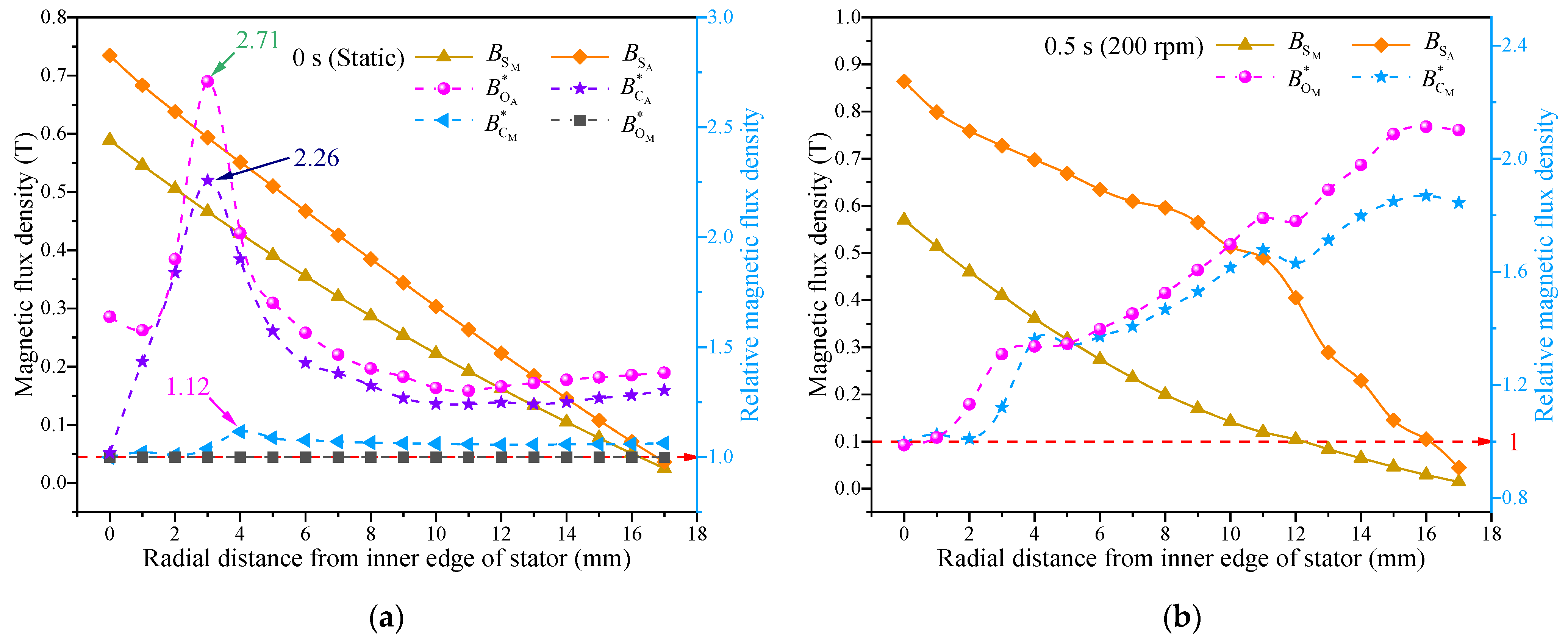
The relative MFD is defined as the ratio of the MFD in the stator of an open-slot/closed-slot IPMECH to that of a solid IPMECH under the same conditions, that is,
B C M * = B C M B S M   ,   B C A * = B C A B S A  
B O M * = B O M B S M   ,   B O A * = B O A B S A  
where, B S M , B C M , and B O M represent the mean of MFD in the stator of solid, closed-slot, and open-slot IPMECHs, respectively. B S A , B C A , and B O A represent the amplitude of MFD in the stator of solid, closed-slot, and open-slot IPMECHs, respectively.
Figure 8 shows a comparison of the MFD along the radial direction in the stator with different structures. From Figure 8a, it can be seen that when the rotor is stationary (i.e., t = 0 s), the mean and amplitude of the MFD of the solid IPMECH stator decrease with the increase in the radial distance from the inner edge of the stator. B C A * and B O A * are both greater than 1 within the range of 1–17 mm, and reach their maximum values of 2.26 and 2.71 at 3 mm, respectively. B O M * is always around 1; B C M * is greater than 1 within the range of 1–17 mm, and reaches its maximum value of 1.12 at 4 mm. Therefore, compared with the solid IPMECH, the closed-slot IPMECH can improve the amplitude and mean of static MFD inside the stator of the heater, while the open-slot IPMECH has little effect on the mean of static MFD inside the stator, and the effect of improving the amplitude of static MFD is more significant. From Figure 8b, it can be seen that when the rotor speed is 200 rpm and runs smoothly (t = 0.5 s), the mean and amplitude of the stator MFD of the solid IPMECH decrease with the increase in the radial distance from the inner edge of stator, B C M * and B O M * show an upward trend with the increase in radial distance from inner edge of stator, and B O M * rises more significantly. B C M * and B O M * are both greater than 1 within the range of 1–17 mm. Therefore, compared with solid, both closed-slot and open-slot IPMECHs can increase the MFD of the stator.
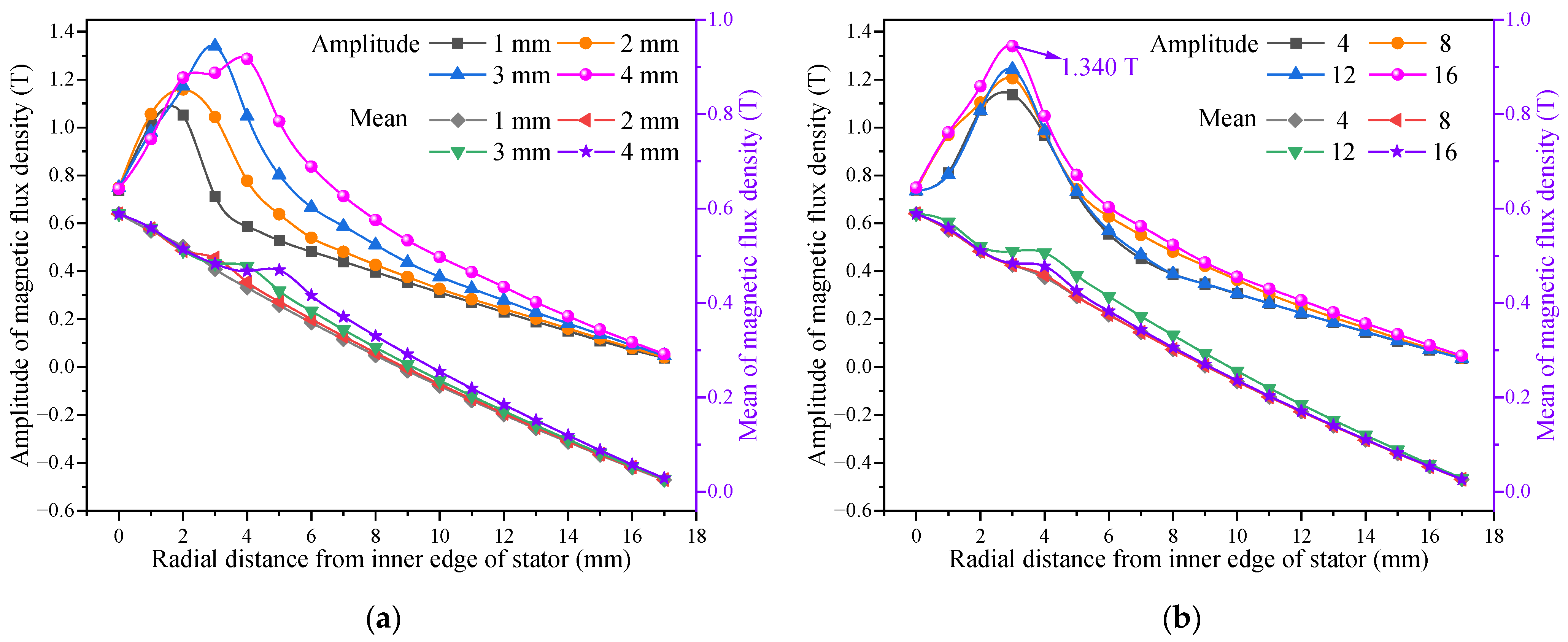
Figure 9 shows the static MFD along the radial direction in the stator of the closed-slot IPMECH with different sizes and quantities of copper strips. Figure 9a shows the amplitude and mean values of static MFD along the radial direction in the stator of the 16-copper-strip closed-slot IPMECH with different copper strip sizes. It can be seen from the figure that the amplitude of static MFD in the stator shows a trend of first increasing and then decreasing along the radial direction, and reaches its maximum value at a certain distance from the inner edge of the stator. As the copper strip size increases, the maximum value is located further away from the inner edge of the stator. The amplitude and mean of the static MFD of the stator increase with the increase of copper strip size within the range of 4–17 mm and 5–17 mm from the inner edge of the stator, respectively. Figure 9b shows the amplitude and mean values of static MFD along the radial direction in the stator of the 3 mm copper strip closed-slot IPMECH with different copper strip quantities. It can be seen from the figure that the amplitude of static MFD in the stator shows a trend of first increasing and then decreasing along the radial direction, and reaches its maximum value at a 3 mm distance from the inner edge of the stator. When the quantity of copper strips is 16, the maximum amplitude of static MFD is 1.340 T. When the quantity of copper strips is 12, the mean of static MFD is the highest.
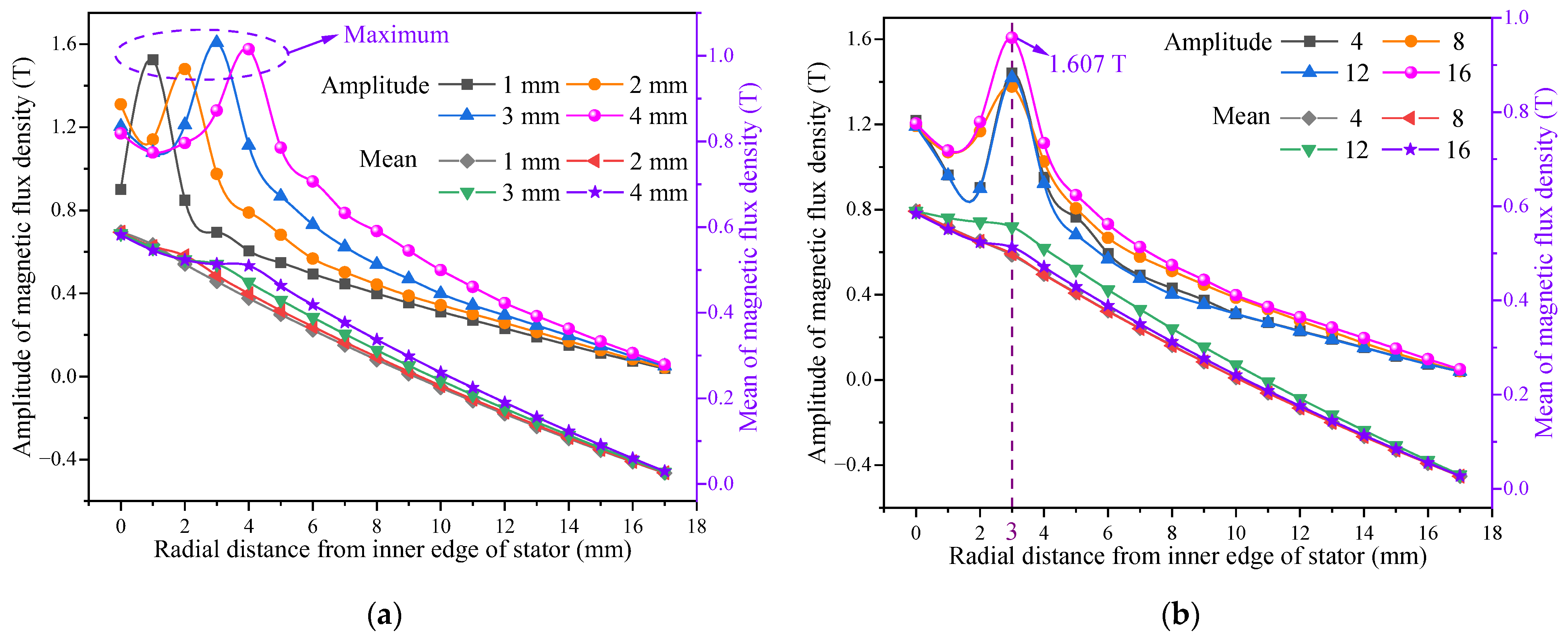
Figure 10 shows the static MFD along the radial direction in the stator of the open-slot IPMECH with different sizes and quantities of copper strips. Figure 10a shows the amplitude and mean values of static MFD along the radial direction in the stator of the 16-copper-strip open-slot IPMECH with different copper strip sizes. From the figure, it can be seen that the static MFD amplitude of the stator of the 1, 2, 3, and 4 mm copper strip size IPMECHs shows a trend of first increasing and then decreasing along the radial direction, and reaches its maximum value at a distance of 1, 2, 3, and 4 mm from the inner edge of the stator, respectively. Figure 10b shows the amplitude and mean values of static MFD along the radial direction in the stator of the 3 mm copper strips open-slot IPMECH with different copper strip quantities. It can be concluded from the figure that the amplitude of the static MFD of the stator reaches its maximum value along the radial direction at a distance of 3 mm from the inner edge of the stator. When the quantity of copper strips is 16, the maximum amplitude of static MFD is 1.607 T. When the quantity of copper strips is 12, the mean of static MFD is the highest.

3.2. Thermal Power and Electromagnetic Torque Characteristics of IPMECH

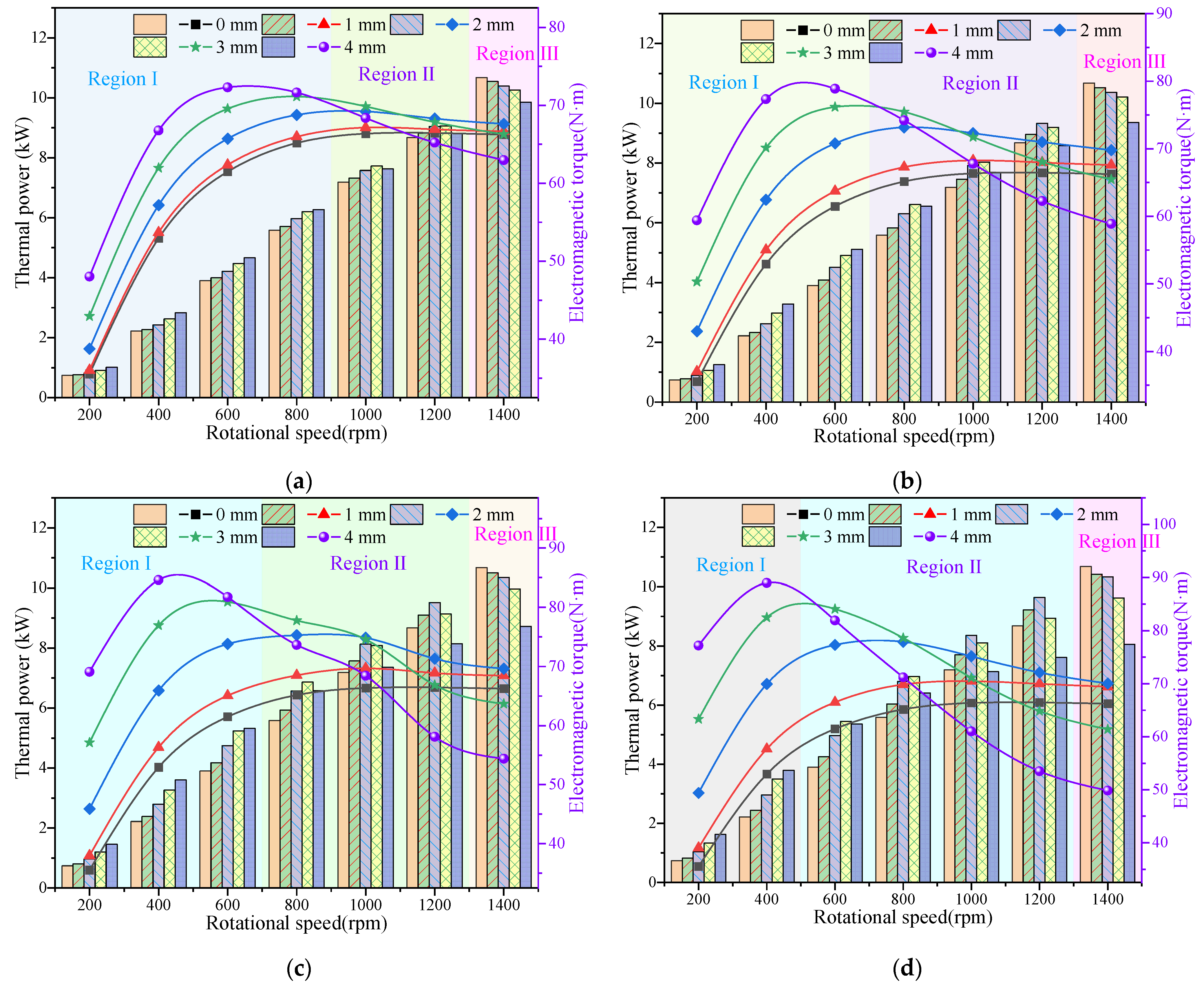
Thermal power and electromagnetic torque are key parameters for the operation of IPMECHs. This section focuses on analyzing the thermal power and electromagnetic torque of solid and closed-slot/open-slot IPMECHs with different copper strip sizes/quantities. In both closed-slot and open-slot IPMECHs, when the copper strip size is 0 mm or the quantity is 0, the heater is a solid IPMECH. The growth rate of the thermal power and electromagnetic torque of closed-slot and open-slot IPMECHs with different sizes or quantities of copper strips relative to the solid IPMECH is defined as the thermal power growth rate (TPGR) and electromagnetic torque growth rate (ETGR). The simulation results of the thermal power and electromagnetic torque of the IPMECH in this article are both average values of 0.3–0.5 s.
Figure 11 shows the thermal power and electromagnetic torque of closed-slot IPMECHs with different copper strip sizes. As can be seen from Figure 11, the thermal power and electromagnetic torque of closed-slot IPMECHs with different copper strip sizes present different trends in Region I (low-rotational-speed region), Region II (medium–high-rotational-speed region), and Region III (high-rotational-speed region). In Region I, the thermal power and electromagnetic torque of the IPMECH increase with the increase in the size of the copper strip, in Region II, they show an increasing and then decreasing trend with the increase in the size of the copper strip, and in Region III, they decrease with the increase in the size of the copper strip. In Region I, the skinning depth corresponding to the rotational speed is much larger than the sum of the size of the copper strip and the distance of the copper strip from the inner edge of the stator. The demagnetization effect of the armature magnetic field inside the stator at lower rotational speeds is relatively small. The presence of copper strips increases the tangential magnetic resistance in the stator, causing the highly saturated magnetic flux region to shift radially. The high conductivity copper strips are linked to the magnetic field, so the larger the size of the copper strips, the greater the thermal power and electromagnetic torque of the heater. As the rotational speed increases, in Region II, the skinning depth corresponding to the rotational speed does not differ much from the sum of the size of the copper strip and the distance of the copper strip from the inner edge of the stator. The armature effect within the stator is stronger, and the magnetic field is mainly concentrated within the skin depth of the stator’s inner surface. The presence of copper strips, while allowing the highly saturated region of magnetic flux to shift along the radial direction, also increases the stator’s magnetic resistance and reduces the MFD in the stator. Therefore, the thermal power and electromagnetic torque increase first and then decrease with the increase in copper strip size. In Region III, the skinning depth corresponding to the rotational speed is less than the sum of the size of the copper strip and the distance of the copper strip from the inner edge of the stator. The rotational speed is higher, the demagnetization effect in the stator is stronger, the presence of copper strips increases the stator magnetoresistance and reduces the stator MFD, the stator magnetic density is mainly concentrated in the region closer to the inner edge of the stator, and the high conductivity of the copper strips cannot be crosslinked with the magnetic field, so the thermal power and the electromagnetic torque of heater decrease with the increase in the size of the copper strips. With the increase in copper strip quantity, the upper limit of rotational speed in Region I presents a decreasing trend. In Region I, increasing the copper strip size can increase the thermal power of the IPMECH.
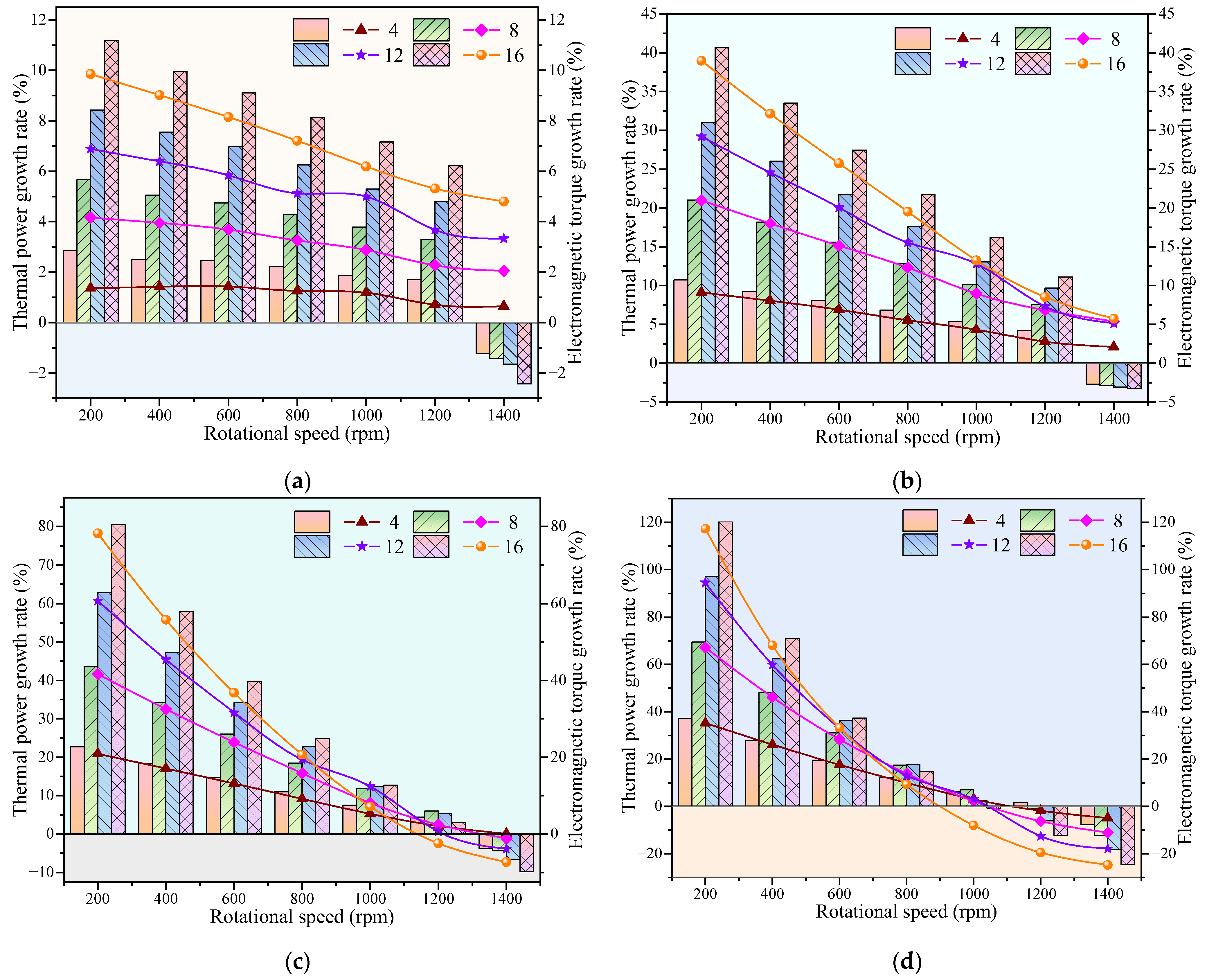
Figure 12 shows the TPGR and ETGR of closed-slot IPMECHs with different copper strip sizes. It can be concluded from the figure that both the TPGR and the ETGR show a decreasing trend with increasing rotational speed. The TPGR and ETGR increase with the increase in copper strip size at Region I, and increase first and then decrease with the increase of copper strip size at Region II. However, the TPGR and ETGR are negative at Region III, and decrease with the increase in copper strip size. Increasing the size of the copper strip in Region I is beneficial to the increase in the thermal power and electromagnetic torque, and the larger the size of the copper strip, the more significant the increase. At 1400 rpm, the presence of copper strips decreases the thermal power and electromagnetic torque of the heater, and the larger the size of the copper strip, the more significant the decrease.
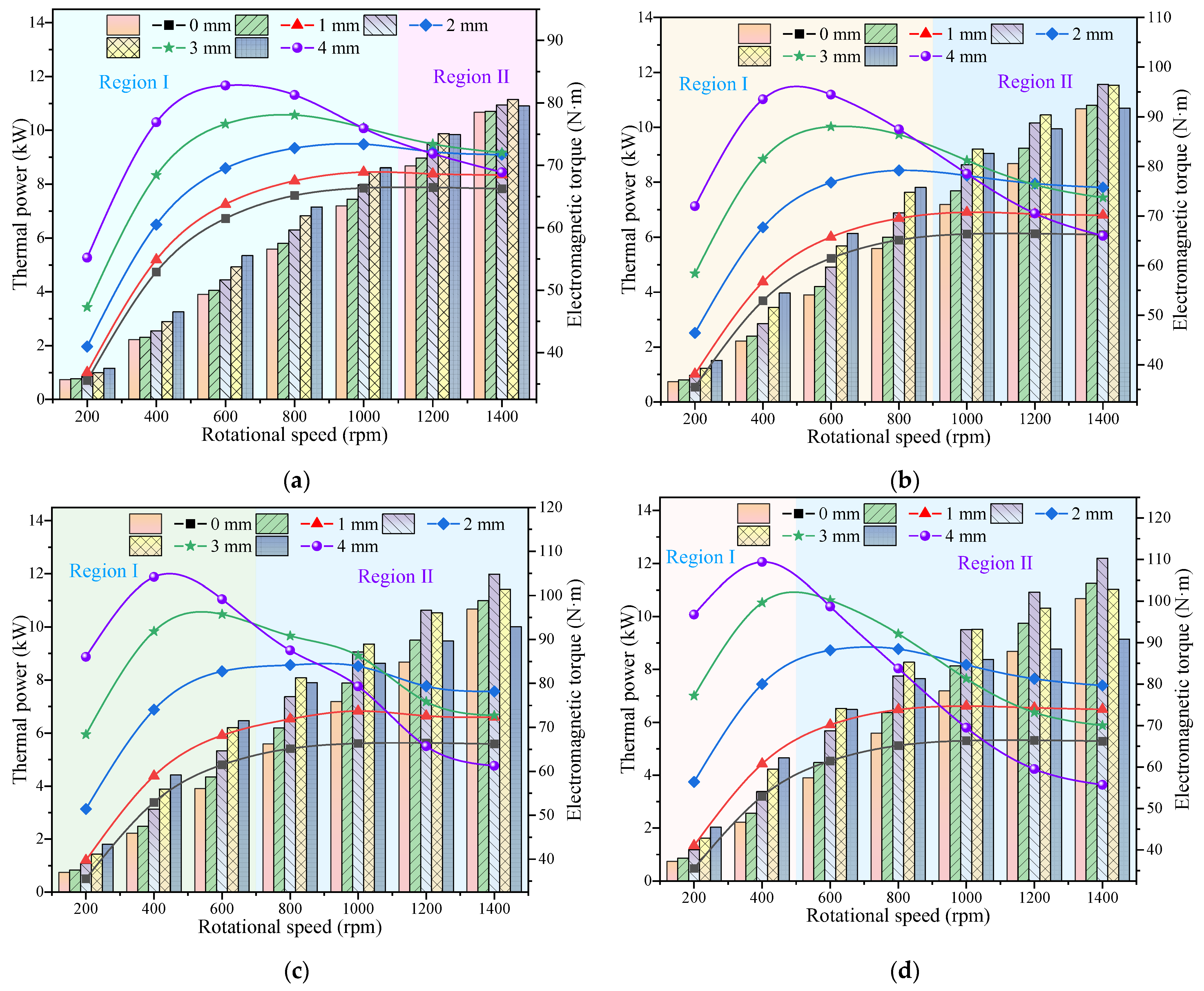
Figure 13 shows the thermal power and electromagnetic torque of closed-slot IPMECHs with different quantities of copper strips. From the figure, when the size of the copper strip is 1 and 2 mm, with the increase in the quantity of copper strips the thermal power of the heaters increases in Region I and decreases in Region III, and with the increase in the quantity of copper strips the electromagnetic torque gradually increases. When the size of the copper strip is 3 and 4 mm, the thermal power of the heater increases with the increase in the quantity of copper strips in Region I, increases and then decreases with the increase in the quantity of copper strips in Region II, and decreases with the increase in the number of copper strips in Region III, and the electromagnetic torque of the heaters with a quantity of copper strips of 4, 8, 12, and 16 shows a tendency of increasing and then decreasing with the increase in the rotational speed. Increasing the quantity of copper strips in Region I increases the thermal power and electromagnetic torque, and the greater the quantity of strips, the more significant the increase. In Region III, the presence of copper strips decreases the thermal power of the heater, and the more copper strips, the more significant the decrease.
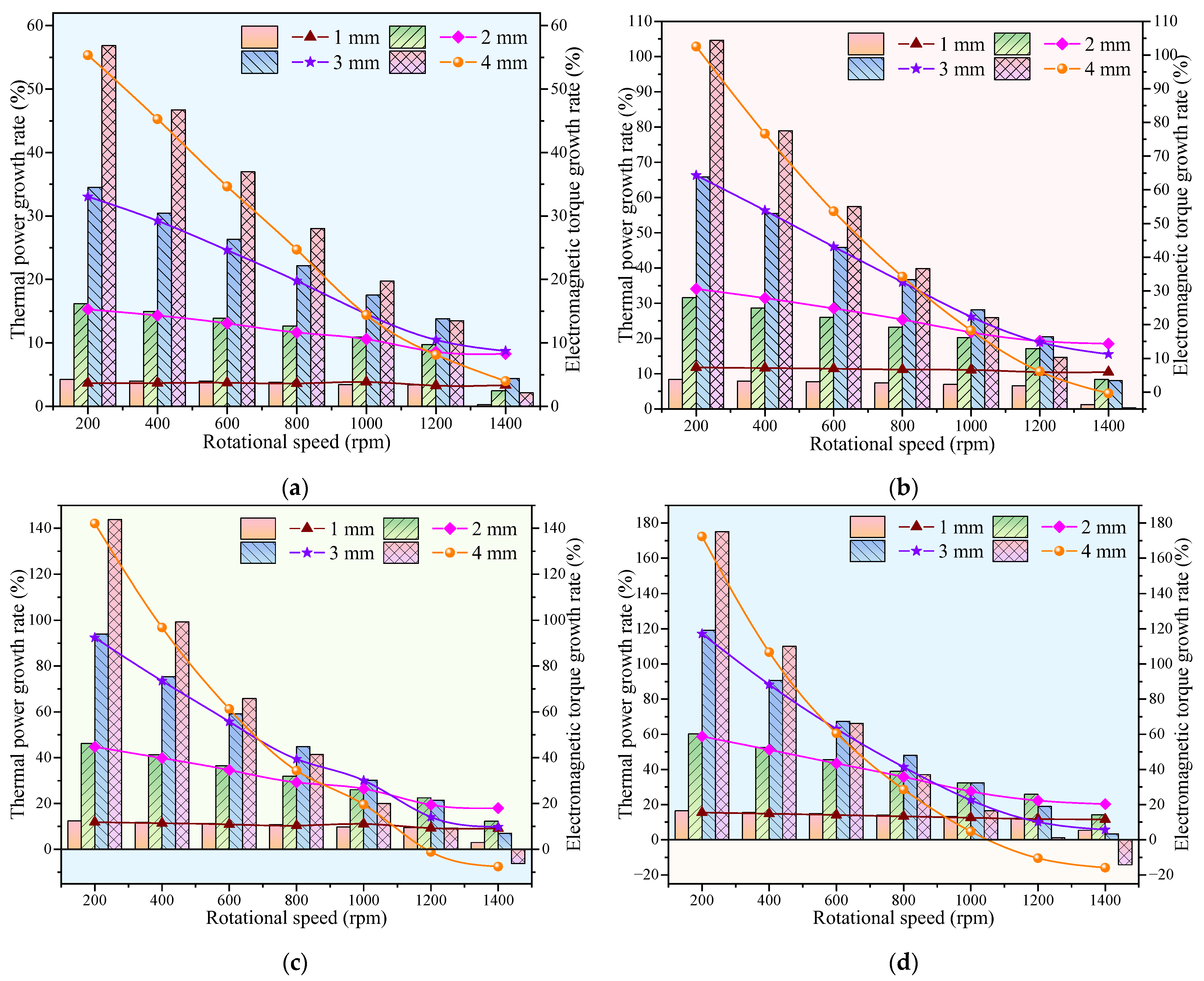
Figure 14 shows the TPGR and the ETGR of closed-slot heaters with different quantities of copper strips. From the figure, it can be obtained that the TPGR and ETGR both show a decreasing trend with the increase in rotational speed. Thermal power and ETGR in Region I increased with the increase in the quantity of copper strips, in Region II showed a trend of increase and then decline with the increase in the quantity of copper strips, and in Region III the thermal power and ETGR had negative values, and with the increase in the quantity of copper strips the growth rate showed a downward trend. When the size and quantity of copper strips are 4 mm and 16, respectively, the TPGRs of the heater at 200 and 1400 rpm are 120.15% and −24.58%, respectively, while the ETGRs are 117.25% and −24.76% respectively. The TPGRs of the closed-slot IPMECH with 3 mm and 16 copper strips at 200 and 1400 rpm are 80.46% and −9.84%, respectively, while the ETGRs are 78.22% and −7.31%, respectively.
Figure 15 shows the thermal power and electromagnetic torque of the open-slot IPMECHs with different copper strip sizes. Figure 15 shows that the open-slot IPMRCH is similar to the closed-slot IPMECH in that it shows different patterns in different rotational speed regions. In Region I, the thermal power and electromagnetic torque of the heaters increase with the increase in copper strip size. In Region II, the thermal power and electromagnetic torque show an increasing and then decreasing trend with the increase in the copper strip size. In the low-rotational-speed region, the heater has a larger skin depth and the open-slot structure increases the tangential magnetoresistance of the stator, resulting in more magnetic flux crosslinking the copper strips and a larger conductivity of the copper strips, which increases the conductivity of the stator, so that the thermal power and the electromagnetic torque increase with the increase in the size of the copper strips. In Region II, the magnetic flux is concentrated at a certain depth on the inner surface of the stator, the magnetic flux and the larger size of the copper strip cannot be completely crosslinked, and when the size of the copper strip is larger, the stator tangential reluctance of the heater is sharply increased, and the magnetic density of the stator region is reduced, so the heater thermal power and electromagnetic torque show a trend of rising and then decreasing with the increase in the size of the copper stirp.
Figure 16 shows the TPGR and ETGR of open-slot IPMECHs with different copper strip sizes. From the figure, it is observed that the TPGR and ETGR both show a decreasing trend with the increase in rotational speed. The growth rate of thermal power and electromagnetic torque increases with the increase in copper strip size in Region I, and increases and then decreases with the increase in copper strip size in Region Ⅱ. The growth rate of thermal power and electromagnetic torque of open-slot 12- and 16-copper-strip IPMECHs with a copper strip size of 4 mm is negative at 1400 rpm and shows a decreasing trend with the increase in the number of copper strips. In Region I, increasing the size of the copper strip is conducive to the enhancement of the thermal power and electromagnetic torque, and the larger the size of the copper strip, the more significant the enhancement. At a rotational speed of 200 rpm, the TPGRs of copper strip sizes of 1, 2, 3, and 4 mm in the open-slot heater with sixteen copper strips are 16.42%, 60.17%, 119.10%, and 175.08%, respectively, and the ETGRs are 15.51%, 58.78%, 117.17%, and 172.36%, respectively.
Figure 17 shows the thermal power and electromagnetic torque of open-slot IPMECHs with different copper strip quantities. As can be seen from the figure, when the size of the copper strip is 1 and 2 mm, the thermal power and electromagnetic torque of the heater increase with the increase in the quantity of copper strips in the rotational speed range of 200–1400 rpm. When the size of the copper strip is 3 and 4 mm, the thermal power of the heater increases with the increase in the quantity of copper strips in Region I, and decreases with the increase in the quantity of copper strips in Region Ⅱ, and the electromagnetic torque of the heater, with the increase in the quantity of copper strips of 4, 8, 12, and 16, shows an increasing trend with the rise in the rotational speed, and then a decreasing trend. Increasing the quantity of copper strips in Region I can improve the thermal power and electromagnetic torque, and the greater the quantity of copper strips, the more significant the increase in the thermal power and the electromagnetic torque. In Region II, too many copper strips will inhibit the increase in thermal power.
Figure 18 shows the TPGR and ETGR of open-slot IPMECHs with different quantities of copper strips. As can be observed from the figure, the TPGR and ETGR show a decreasing trend with the increase in rotational speed, and the greater the quantity of copper strips, the more rapid the decrease. The TPGR and ETGR of the heater in the range of 200–1400 rpm increases with the increase in the quantity of copper strips when the size of the copper strips is 1 and 2 mm. When the copper strip size is 3 and 4 mm, the TPGR and ETGR of the heater increases with the increase in the quantity of copper strips in Region I. In Region II, the TPGR and ETGR show an increasing and then decreasing trend with the increase in the quantity of copper strips, and the growth rate of thermal power and electromagnetic torque may even be negative. When the size and quantity of copper strips are 4 mm and 16, respectively, the TPGRs of the heater at 200 and 1400 rpm are 175.08% and −14.32%, respectively, while the ETGRs are 172.36% and −15.91%, respectively. The TPGRs of the open-slot IPMECH with 16 3 mm copper strips at 200 and 1400 rpm are 119.10% and 3.32%, respectively, while the ETGRs are 117.17% and 5.69%, respectively.

3.3. Experiment of Prototypes

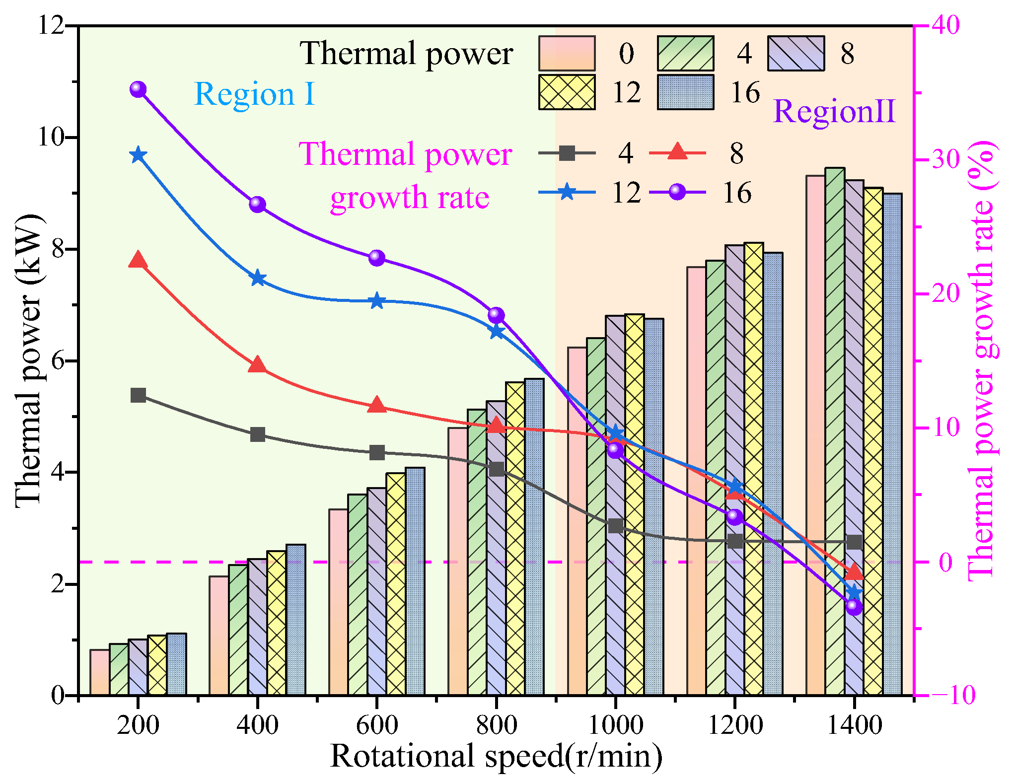
Figure 19 shows the thermal power and TPGR of the closed-slot prototype with different quantities of copper strips. The size of the copper strips in the closed-slot prototype is 3 mm, and the other parameters are shown in Table 3. It can be seen from the figure that the thermal power of the prototype shows an upward trend with the increase in rotational speed. The thermal growth rate of the heater shows a downward trend with the increase in rotational speed, and the downward trend with the increase in the quantity of copper strips is more sharp. The TPGRs of the heaters with a quantity of copper strips of 8, 12, and 16 are negative at the rotational speed of 1400 rpm. In Region I, the thermal power of the heater increases gradually with the increase in the quantity of copper strips. In Region II, the thermal power of the heater increases with the increase in the quantity of copper strips and then decreases, and the quantity of copper strips, with the same rotational speed corresponding to the maximum thermal power, decreases with the increase in rotational speed. At a rotational speed of 200 rpm, the TPGRs of the closed-slot prototype with four, eight, twelve, and sixteen copper strips are 12.43%, 22.42%, 30.34%, and 35.24%, respectively.
Figure 20 shows the thermal power and TPGR of the open-slot prototype with different quantities of copper strips. The size of the copper strips in the open-slot prototype is 3 mm, and the other parameters are shown in Table 3. From the figure, it can be shown that the thermal power of the prototype shows an upward trend with the increase in rotational speed, and the TPGR shows a downward trend with the increase in rotational speed, and the greater the quantity of copper strips, the more rapid the decline. In the rotational speed range of 200–1400 rpm, the TPGR of the heater is above 0. In Region I, the thermal power and the TPGR of the heater increase gradually with the increase in the quantity of copper strips. In Region II, the thermal power and TPGR of the heater show an increasing and then decreasing trend with the increase in the quantity of copper strips. At a rotational speed of 200 rpm, the TPGRs of the open-slot prototype with four, eight, twelve, and sixteen copper strips are 26.17%, 38.79%, 51.17%, and 61.09%, respectively.
Comparison of the simulation and experimental results of the thermal power of the closed- and open-slot heaters shows that the simulation results have a similar pattern to the experimental results, and the simulation results are higher than the experimental results. The main reasons for the experimental results being lower than the simulation results are as follows: (1) the simulation does not take into account the end effect of the heater, resulting in the simulation results being larger than the actual value; (2) the effect of temperature on the conductivity and magnetic permeability of the heater material is neglected in the simulation; (3) the copper strips of the heater prototype could not be seamlessly embedded in the stator during machining and fabrication, increasing the resistance in the stator; (4) the material selected in the simulation is monolithic and isotropic, while the material in the prototype still has impurities, and the permeability and conductivity are reduced; and (5) heat loss is ignored during the experiment. The experimental results can verify the reasonableness and accuracy of the simulation results, as the experimental results have a similar pattern to the simulation results and the results have little difference.

4. Conclusions

In this paper, the equations for calculating the electromagnetic field, thermal power, and electromagnetic torque of an IPMECH are given, the flux density distributions of heaters with different stator structures are analyzed, the thermal power and electromagnetic torque of solid and closed-slot/open-slot IPMECHs with different sizes/quantities of copper strips are studied, and the operating characteristics of closed-slot and open-slot prototypes are experimentally explored. It is found that in RegionⅠ, the proper placement of copper strips in the stator enhances the thermal power and electromagnetic torque of the closed-slot and open-slot IPMECHs, and the following conclusions are drawn:
  • Compared with the solid IPMECH, the closed-slot and open-slot IPMECHs can improve the heaters’ stator MFD, and the stator static MFD amplitudes of closed-slot and open-slot IPMECHs with 16 3 mm copper strips are 1.340 and 1.607 T, respectively.
  • Compared with the solid IPMECH, the thermal power and electromagnetic torque of the closed-slot IPMECH can be enhance in Region Ⅰ, while it can be reduced in Region II. The TPGRs of the closed-slot IPMECH with 16 3 mm copper strips at 200 and 1400 rpm are 80.46% and −9.84%, respectively, while the ETGRs are 78.22% and −7.31%, respectively.
  • Enhancement of thermal power and electromagnetic torque by the open-slot IPMECH is more significant. The TPGRs of the open-slot IPMECH with 16 3 mm copper strips at 200 and 1400 rpm are 119.10% and 3.32%, respectively, while the ETGRs are 117.17% and 5.69%, respectively.
  • At 200 rpm, the TPGRs of the closed-slot prototype with four, eight, twelve, and sixteen copper strips are 12.43%, 22.42%, 30.34%, and 35.24%, respectively, while the TPGRs of the open-slot prototype are 26.17%, 38.79%, 51.17%, and 61.09%, respectively. The experimental results verify the accuracy and reliability of the simulation results.
  • End effects and temperature effects on the physical properties of the material are neglected during numerical simulations in this paper. In the future, magnetic–thermal coupling analysis will be performed on the heat generator to further optimize it.

Author Contributions

Conceptualization, H.L. and W.H.; methodology, H.L.; software, W.H.; validation, H.L.; formal analysis, H.L.; investigation, W.H.; resources, W.H.; data curation, H.L.; writing—original draft preparation, H.L.; writing—review and editing, H.L.; visualization, H.L.; supervision, W.H.; project administration, W.H.; funding acquisition, W.H. All authors have read and agreed to the published version of the manuscript.

Funding

This project is supported by the Science and Technology Development Plan of Jilin Province, grant number no. 20210203200SF.

Data Availability Statement

The original contributions presented in the study are included in the article; further inquiries can be directed to the corresponding author.

Conflicts of Interest

The authors declare no conflicts of interest.

Abbreviations

The following abbreviations are used in this manuscript:
PMECHPermanent magnet eddy current heater
IPMECHInterior permanent magnet eddy current heater
MFDMagnetic flux density
AMFDAir gap magnetic flux density
TPGRThermal power growth rate
ETGRElectromagnetic torque growth rate
Symbols
E The electric field (V/m)
B The magnetic flux density (MFD) (T)
H The magnetic field intensity (A/m)
J The current density (A/m2)
D The electric displacement (C/m2)
ρ The charge density (C/m3)
ε The permittivity
μ The permeability (H/m)
σ The conductivity (S/m)
ε 0 The vacuum permittivity
μ 0 The vacuum permeability (H/m)
μ r The relative permeability
ω The angular velocity of magnetic field variation (rad/s)
θ The phase angle of the solution point (°)
n The rotational speed (rpm)
H m The amplitude of external magnetic field strength (A/m)
P e The thermal power of IPMECH
c w The specific heat capacity of water (mm)
m w The quality of water in the experiment (kg)
T e The water temperature in the water tank at the end of the experiment (°C)
T 0 The water temperature in the water tank at the beginning of the experiment (°C)
t e The operating time of IPMECH (s)

Appendix A

The output thermal energy of the heater can be obtained by the following equation:
Q = c w m w Δ T
Δ T = ( T e T 0 )
The uncertainty U of the output energy Q is given by the following equation:
U = ( Q c w U c w Q ) 2 + ( Q m w U m w Q ) 2 + ( Q Δ T U Δ T Q ) 2 0.5
where U is the uncertainty of the output energy Q .
According to partial differential equation (A3), we can derive the following equation:
U = ( m w Δ T U c w Q ) 2 + ( c w Δ T U m w Q ) 2 + ( c w m w U Δ T Q ) 2 0.5
Then,
U = ( U c w c w ) 2 + ( U m w m w ) 2 + ( U Δ T Δ T ) 2 0.5
The uncertainty of temperature change is determined as follows:
U Δ T Δ T = ( Δ T T 0 U T 0 Δ T ) 2 + ( Δ T T e U T e Δ T ) 2 0.5
By combining Equations (A2) and (A6), we can obtain the following:
U Δ T Δ T = ( U T 0 Δ T ) 2 + ( U T e Δ T ) 2 0.5
Considering that the beginning and the end temperatures of the experiment T 0 and T e are equal,
U Δ T Δ T = 2 ( U T Δ T ) 2 0.5
Finally, the uncertainty for the output energy ( Q ) is as follows:
U = ( U c w c w ) 2 + ( U m w m w ) 2 + 2 ( U T Δ T ) 2 0.5
In the case of uncertain physical properties, the uncertainty of the water-specific heat capacity ( c w ) is 0.3%. In this experiment, the uncertainty of t e is very small and can be ignored, so the uncertainty U of the output thermal energy ( Q ) can be regarded as the uncertainty of thermal power ( P e ).
Table A1. The relative uncertainty of the output energy of the solid IPMECH.
StructuralrpmParameterMeasurementUnitAccuracyRelative Uncertainty
solid200 c w 4.183kJ/kg/°C0.3%0.36%
m w 30kg±1 g
Δ T 7.9°C0.2%
400 c w 4.183kJ/kg/°C0.3%0.36%
m w 60kg±1 g
Δ T 10.2°C0.2%
600 c w 4.183kJ/kg/°C0.3%0.36%
m w 60kg±1 g
Δ T 16.4°C0.2%
800 c w 4.183kJ/kg/°C0.3%0.36%
m w 60kg±1 g
Δ T 22.9°C0.2%
1000 c w 4.183kJ/kg/°C0.3%0.36%
m w 60kg±1 g
Δ T 29.8°C0.2%
1200 c w 4.183kJ/kg/°C0.3%0.36%
m w 60kg±1 g
Δ T 36.7°C0.2%
1400 c w 4.183kJ/kg/°C0.3%0.36%
m w 60kg±1 g
Δ T 44.5°C0.2%
Table A2. The relative uncertainty of the output energy of the closed-slot IPMECH.
StructuralrpmParameterMeasurementUnitAccuracyRelative Uncertainty
solid200 c w 4.183kJ/kg/°C0.3%0.36%
m w 30kg±1 g
Δ T 10.6°C0.2%
400 c w 4.183kJ/kg/°C0.3%0.36%
m w 60kg±1 g
Δ T 12.9°C0.2%
600 c w 4.183kJ/kg/°C0.3%0.36%
m w 60kg±1 g
Δ T 19.5°C0.2%
800 c w 4.183kJ/kg/°C0.3%0.36%
m w 60kg±1 g
Δ T 27.1°C0.2%
1000 c w 4.183kJ/kg/°C0.3%0.36%
m w 60kg±1 g
Δ T 32.3°C0.2%
1200 c w 4.183kJ/kg/°C0.3%0.36%
m w 60kg±1 g
Δ T 37.9°C0.2%
1400 c w 4.183kJ/kg/°C0.3%0.36%
m w 60kg±1 g
Δ T 43.0°C0.2%
Table A3. The relative uncertainty of the output energy of the open-slot IPMECH.
StructuralrpmParameterMeasurementUnitAccuracyRelative Uncertainty
solid200 c w 4.183kJ/kg/°C0.3%0.36%
m w 30kg±1 g
Δ T 12.4°C0.2%
400 c w 4.183kJ/kg/°C0.3%0.36%
m w 60kg±1 g
Δ T 13.5°C0.2%
600 c w 4.183kJ/kg/°C0.3%0.36%
m w 60kg±1 g
Δ T 19.6°C0.2%
800 c w 4.183kJ/kg/°C0.3%0.36%
m w 60kg±1 g
Δ T 27.0°C0.2%
1000 c w 4.183kJ/kg/°C0.3%0.36%
m w 60kg±1 g
Δ T 33.5°C0.2%
1200 c w 4.183kJ/kg/°C0.3%0.36%
m w 60kg±1 g
Δ T 39.3°C0.2%
1400 c w 4.183kJ/kg/°C0.3%0.36%
m w 60kg±1 g
Δ T 44.5°C0.2%

References

  1. Zhou, G.; Bahn, G.; Lao, J.; Zhang, Y. COP28 Targets for Mobilizing Private Investment in Fossil Fuels Extraction Industry to Cope with the Climate Change. Resour. Policy 2024, 97, 105285. [Google Scholar] [CrossRef]
  2. Acen, C.; Bamisile, O.; Cai, D.; Ukwuoma, C.C.; Obiora, S.; Huang, Q.; Uzun Ozsahin, D.; Adun, H. The Complementary Role of Carbon Dioxide Removal: A Catalyst for Advancing the COP28 Pledges towards the 1.5 °C Paris Agreement Target. Sci. Total Environ. 2024, 947, 174302. [Google Scholar] [CrossRef] [PubMed]
  3. IEA. Energy System Buildings Overview. World Energy Outlook 2024-Event-IEA. Available online: https://www.iea.org/energy-system/buildings/ (accessed on 29 December 2024).
  4. He, Y.; Zhu, C.; Cao, C. A Wind Power Ramp Prediction Method Based on Value-at-Risk. Energy Convers. Manag. 2024, 315, 118767. [Google Scholar] [CrossRef]
  5. GWEC. Global Wind Report 2024; Global Wind Energy Council: Gewest, Belgium, 2024; p. 75. Available online: https://www.gwec.net/reports/globalwindreport (accessed on 7 December 2024).
  6. You, G.D.; Chang, Z.C.; Li, X.Y.; Liu, Z.F.; Xiao, Z.Y.; Lu, Y.R.; Zhao, S. Using Enhanced Variational Modal Decomposition and Dung Beetle Optimization Algorithm Optimization-Kernel Extreme Learning Machine Model to Forecast Short-Term Wind Power. Electr. Power Syst. Res. 2024, 236, 110904. [Google Scholar] [CrossRef]
  7. Li, J.; Meng, F.; Zhang, Z.; Zhang, Y. Prediction of Wind Power Ramp Events via a Self-Attention Based Deep Learning Approach. Energy Rep. 2024, 12, 1488–1502. [Google Scholar] [CrossRef]
  8. Miao, Q.; Wang, D.; Xia, Z.; Xu, C.; Zhan, J. Exploring Spatio-Temporal Dynamics for Enhanced Wind Turbine Condition Monitoring. Mech. Syst. Signal Process 2025, 223, 111841. [Google Scholar] [CrossRef]
  9. Fang, Y.; Fan, R.; Shao, Z.; Yue, Y.; Liu, Z. Research on the Cost Allocation Mechanism of Wind Power Heating in China from a Cost-Benefit Perspective. Energy Rep. 2024, 11, 4622–4630. [Google Scholar] [CrossRef]
  10. Wang, W.; Dong, Z. Economic Benefits Assessment of Urban Wind Power Central Heating Demonstration Project Considering the Quantification of Environmental Benefits: A Case from Northern China. Energy 2021, 225, 120246. [Google Scholar] [CrossRef]
  11. Mu, Y.; Li, H.; Yu, X.; Jia, H.; Wang, M.; Hou, K.; Wang, Z. A Scenario-Based Optimal Dispatch for Joint Operation of Wind Farms and Combined Heat and Power Plants Considering Energy Flexibilities in Heating Networks. Electr. Power Syst. Res. 2022, 204, 107683. [Google Scholar] [CrossRef]
  12. Lei, Z.; Wang, G.; Li, T.; Cheng, S.; Yang, J.; Cui, J. Strategy Analysis about the Active Curtailed Wind Accommodation of Heat Storage Electric Boiler Heating. Energy Rep. 2021, 7, 65–71. [Google Scholar] [CrossRef]
  13. Nourollahi, R.; Zare, K.; Mohammadi-Ivatloo, B.; Vahidinasab, V.; Moghadam, A.A. Continuous-Time Optimization of Integrated Networks of Electricity and District Heating under Wind Power Uncertainty. Appl. Therm. Eng. 2023, 225, 119926. [Google Scholar] [CrossRef]
  14. Cheng, W.L.; Han, B.C.; Nian, Y.L.; Han, B.B. Theoretical Analysis of a Wind Heating Conversion and Long Distance Transmission System. Energy Convers. Manag. 2017, 137, 21–33. [Google Scholar] [CrossRef]
  15. Liu, D.; Zhang, S.; Cheng, H.; Liu, L.; Zhang, J.; Zhang, X. Reducing Wind Power Curtailment by Risk-Based Transmission Expansion Planning. Int. J. Electr. Power Energy Syst. 2021, 124, 106349. [Google Scholar] [CrossRef]
  16. Zheng, J.; Zhou, Z.; Zhao, J.; Wang, J. Effects of the Operation Regulation Modes of District Heating System on an Integrated Heat and Power Dispatch System for Wind Power Integration. Appl. Energy 2018, 230, 1126–1139. [Google Scholar] [CrossRef]
  17. Javed, M.H.; Duan, X. Experimental Study of Kinetic to Thermal Energy Conversion with Fluid Agitation for a Wind-Powered Heat Generator. Energies 2024, 17, 4246. [Google Scholar] [CrossRef]
  18. Liu, X.; Sun, X.; He, J.; Wang, D.; Qiu, X.; Bi, S.; Cao, Y. Study on the Influence of Working-Fluid’s Thermophysical Properties on the Stirring-Heating. Energies 2022, 15, 4835. [Google Scholar] [CrossRef]
  19. Serov, A.F.; Nazarov, A.D.; Mamonov, V.N.; Terekhov, V.I. Experimental Investigation of Energy Dissipation in the Multi-Cylinder Couette-Taylor System with Independently Rotating Cylinders. Appl. Energy 2019, 251, 113362. [Google Scholar] [CrossRef]
  20. Iyer, K.R.; Roozbahani, H.; Alizadeh, M.; Handroos, H. A Novel Approach for Direct Conversion of Wind Energy to Heat Utilizing a Hydraulic Medium for Domestic Heating Applications. Energy Rep. 2022, 8, 11139–11150. [Google Scholar] [CrossRef]
  21. Zdankus, T.; Cerneckiene, J.; Jonynas, R.; Stelmokaitis, G.; Fokaides, P.A. Experimental Investigation of a Wind to Thermal Energy Hydraulic System. Renew. Energy 2020, 159, 140–150. [Google Scholar] [CrossRef]
  22. Chen, L.; Pei, Y.; Chai, F.; Cheng, S. Investigation of a Novel Mechanical to Thermal Energy Converter Based on the Inverse Problem of Electric Machines. Energies 2016, 9, 518. [Google Scholar] [CrossRef]
  23. Cheng, H.; Yang, Q.; Ding, Y.; Wang, L.; Yang, G. Optimization Design and Heat Performance Analysis of a Cylindrical Wind-Magnetic Eddy Current Heater. Int. J. Therm. Sci. 2025, 210, 109606. [Google Scholar] [CrossRef]
  24. Chen, Y.-C.B. Direct Wind-to-Heat Energy Systems Integrated with Storage for Electricity and Heat Generation. Ph.D. Thesis, University of Birmingham, Birmingham, UK, 2021. [Google Scholar]
  25. Hadadi, S.; Kang, S.; Park, G.; Lee, J.H. Analysis of the Eddy Current of Water Heating Device to Convert Wind Energy Directly into Heat: Case Study Maldo Island, South Korea. Appl. Energy 2024, 376, 124192. [Google Scholar] [CrossRef]
  26. Cao, K.K.; Nitto, A.N.; Sperber, E.; Thess, A. Expanding the Horizons of Power-to-Heat: Cost Assessment for New Space Heating Concepts with Wind Powered Thermal Energy Systems. Energy 2018, 164, 925–936. [Google Scholar] [CrossRef]
  27. Sobor, I.; Chicuic, A.; Ciuperca, R.; Rachier, V. Concerning the Conversion Efficiency Increase of the Available Wind Potential. Ann. Univ. Craiova Electr. Eng. Ser. 2011, 35, 122–127. [Google Scholar]
  28. Liu, X.H.; Chen, C.C.; Yu, H.D.; Wei, G.D.; Tian, Z. De The Study of the Heat Device in Wind-Magnetic Water Heater. Adv. Mat. Res. 2011, 201–203, 460–464. [Google Scholar] [CrossRef]
  29. Du, H.; Qu, Y.; Cheng, S. A Novel Dynamic Electromagnetic Heating-Magnetizing Device Used for Reverse Osmosis System. Adv. Mater. Res. 2012, 562–564, 913–916. [Google Scholar] [CrossRef]
  30. Du, H.; Qu, Y. Research on Loss and Temperature Rise of a Novel Dynamic Electromagnetic Induction Heater. Adv. Mater. Res. 2012, 468–471, 3108–3112. [Google Scholar] [CrossRef]
  31. Du, H.; Li, J.; Qu, Y. Mathematical Modeling of Eddy-Current Loss for a New Induction Heating Device. Math. Probl. Eng. 2014, 2014, 923745. [Google Scholar] [CrossRef]
  32. Cheng, S.; Chen, L.; Hou, Y.; Zhao, W.; Lei, T. Fundamental Research on Flameless Electromagnetic Heater Based on the Reverse Problem of Temperature Rise and Loss in Electrical Machines. In Proceedings of the 2008 IEEE Vehicle Power and Propulsion Conference, Harbin, China, 3–5 September 2008; IEEE: Piscataway, NJ, USA, 2008. [Google Scholar]
  33. Chu, J. Mathematic Model Based on Rotating Electromagnetic Theory Used in Building a Thermal Circuit Used in Food Heater. Carpathian J. Food Sci. Technol. 2016, 8, 106–113. [Google Scholar]
  34. Lu, H.; Zhang, L.; Hong, W. Thermal Power Calculation of Interior Permanent Magnet Eddy Current Heater Using Analytical Method. Processes 2024, 12, 1457. [Google Scholar] [CrossRef]
  35. Shi, Z.; Sun, X.; Yang, Z.; Cai, Y.; Lei, G.; Zhu, J.; Lee, C.H.T. Design Optimization of a Spoke-Type Axial-Flux PM Machine for In-Wheel Drive Operation. IEEE Trans. Transp. Electrif. 2024, 10, 3770–3781. [Google Scholar] [CrossRef]
  36. Shi, Z.; Sun, X.; Lei, G.; Tian, X.; Guo, Y.; Zhu, J. Multiobjective Optimization of a Five-Phase Bearingless Permanent Magnet Motor Considering Winding Area. IEEE/ASME Trans. Mechatron. 2022, 27, 2657–2666. [Google Scholar] [CrossRef]
  37. Sun, X.; Xu, N.; Yao, M. Sequential Subspace Optimization Design of a Dual Three-Phase Permanent Magnet Synchronous Hub Motor Based on NSGA III. IEEE Trans. Transp. Electrif. 2023, 9, 622–630. [Google Scholar] [CrossRef]
  38. Tudorache, T.; Popescu, M. FEM Optimal Design of Wind Energy-Based Heater. Acta Polytech. Hung. 2009, 6, 55–70. [Google Scholar]
  39. Fireeanu, V.; Nebi, O. Finite element electromagnetic 2d model of an eddy current heater with rotating permanent magnets. Ann. Univ. Craiova Electr. Eng. Ser. 2008, 32, 62–67. [Google Scholar]
  40. Yuan, J.; Liu, N.; Zhang, W.; Peng, B.; Dong, W. Study on the Effect of Changing Stator Structure on Wind Permanent Magnet Eddy Current Heating Device. Energy Rep. 2022, 8, 592–600. [Google Scholar] [CrossRef]
  41. Dirba, I.; Kleperis, J. Practical Application of Eddy Currents Generated by Wind. In IOP Conference Series: Materials Science and Engineering; IOP Publishing: Bristol, UK, 2011; Volume 23. [Google Scholar]
  42. Lu, H.; Zhou, C.; Hong, W.; Ding, H. Research on the Mechanism of Thermal Power Enhancement in an Interior Permanent Magnet Eddy Current Heater Driven by Wind. Processes 2024, 12, 2390. [Google Scholar] [CrossRef]
  43. Khanjari, A.; Kang, S.; Lee, D.; Jung, D.Y.; Lee, J.H. Studying Four Different Permanent Magnet Eddy Currents Heaters with Different Magnet Areas and Numbers to Produce Heat Directly from a Vertical Axis Wind Turbine. Energies 2022, 15, 275. [Google Scholar] [CrossRef]
  44. Khanjari, A.; Kang, S.; Lee, S.I.; Lee, J.H.; Kim, Y.S. Direct Heat Energy Harvesting from Wind by a Permanent Magnet Eddy Currents Heater with Different Magnet Arrangements. Energy Sci. Eng. 2023, 11, 929–951. [Google Scholar] [CrossRef]
  45. Sobor, I.; Rachier, V.; Chicuic, A.; Ciuperca, R. Small Wind Energy System with Permanent Magnet Eddy Current Heater. Bull. Polytech. Inst. Jassy Elechtrotech. Energetics Electron. Sect. 2013, 13, 143–150. [Google Scholar]
  46. Tudorache, T.; Melcescu, L.; Bostan, V.; Colț, G.; Popescu, M.; Predescu, M. Electromagnetic analysis of a hybrid permanent magnet generator. Rev. Roum. des Sci. Tech. Ser. Electrotech. Energ. 2018, 63, 33–37. [Google Scholar]
  47. Tudorache, T.; Melcescu, L.; Predescu, M. Analysis of a Permanent Magnet Eddy Current Heater Driven by a Wind Turbine. Adv. Electr. Comput. Eng. 2015, 15, 53–58. [Google Scholar] [CrossRef]
  48. Tudorache, T.; Melcescu, L. Outer Rotor Eddy Current Heater for Wind Turbines. Renew. Energy Environ. Sustain. 2016, 1, 25. [Google Scholar] [CrossRef]
  49. Song Zhihao, Y.W.W. Modeling of Interior PMSM Based on Normal Canonical Form Under Low Carrier Ratio. Proc. CSEE 2023, 43, 4779–4788. [Google Scholar]
  50. Liu, F.; Wang, X.; Xing, Z.; Yu, A.; Li, C. Reduction of Cogging Torque and Electromagnetic Vibration Based on Different Combination of Pole Arc Coefficient for Interior Permanent Magnet Synchronous Machine. CES Trans. Electr. Mach. Syst. 2021, 5, 291–300. [Google Scholar] [CrossRef]
  51. Karakoc, K.; Park, E.J.; Suleman, A. Improved Braking Torque Generation Capacity of an Eddy Current Brake with Time Varying Magnetic Fields: A Numerical Study. Finite Elem. Anal. Des. 2012, 59, 66–75. [Google Scholar] [CrossRef]
  52. Gu, G.; Chen, F.; Ma, T.; Xu, F.; Yang, D. Electromagnetic and Mechanical Properties of Soft Magnetic Cement Composite for Airport Runway Induction Heating: Experimental and Simulation Analyses. J. Clean. Prod. 2022, 332, 130141. [Google Scholar] [CrossRef]
  53. Li, F.; Li, X.; Wang, T.; Rong, Y.; Liang, S.Y. In-Process Residual Stresses Regulation during Grinding through Induction Heating with Magnetic Flux Concentrator. Int. J. Mech. Sci. 2020, 172, 105393. [Google Scholar] [CrossRef]
  54. Lu, H.; Zhou, C.; Hong, W.; Ding, H. Thermal Power and the Structural Parameters of a Wind Turbine Permanent Magnet Eddy Current Heater. Processes 2024, 12, 2398. [Google Scholar] [CrossRef]
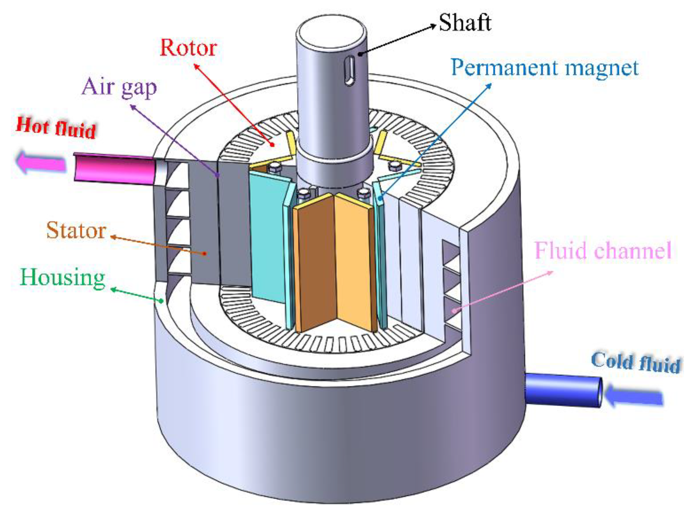
Figure 1. Permanent magnet eddy current heater [42].
Energies 18 00932 g001
Figure 2. IPMECH model and magnetization direction. (a) Solid IPMECH; (b) closed-slot IPMECH; (c) open-slot IPMECH; and (d) magnet magnetization direction.
Energies 18 00932 g002
Figure 3. Independence verification. (a) Mesh; (b) time step.
Energies 18 00932 g003
Figure 4. Ref. [54]. IPMECH experimental platform. (a) The schematic diagram of the experimental system; (b) the experimental platform.
Energies 18 00932 g004
Figure 5. Flux distribution of IPMECH with different structures. (a) Solid (t = 0 s); (b) closed-slot (t = 0 s); (c) open-slot (t = 0 s); (d) solid (t = 0.5 s); (e) closed-slot (t = 0.5 s); (f) open-slot (t = 0.5 s).
Energies 18 00932 g005
Figure 6. AMFD. (a) The AMFD at different positions and times; (b) mean values and amplitudes of the AMFD in the solid IPMECH; (c) mean values and amplitudes of the AMFD in the closed-slot IPMECH; and (d) mean values and amplitudes of the AMFD in the open-slot IPMECH.
Energies 18 00932 g006
Figure 7. Amplitudes and mean values of the MFD along the radial direction in the stator at different rotational speeds. (a) Solid IPMECH; (b) closed-slot IPMECH; and (c) open-slot IPMECH.
Energies 18 00932 g007
Figure 8. Comparison of the MFD along the radial direction in the stator with different structures. (a) t = 0 s; (b) t = 0.5 s.
Energies 18 00932 g008
Figure 9. The static MFD along the radial direction in the stator of the closed-slot IPMECH with different sizes and quantities of copper strips. (a) Different sizes; (b) different quantities.
Energies 18 00932 g009
Figure 10. The static MFD along the radial direction in the stator of the open-slot IPMECH with different sizes and quantities of copper strips. (a) Different sizes; (b) different quantities.
Energies 18 00932 g010
Figure 11. Thermal power and electromagnetic torque of closed-slot IPMECHs with different copper strip sizes. (a) Four copper strips; (b) eight copper strips; (c) twelve copper strips; and (d) sixteen copper strips.
Energies 18 00932 g011
Figure 12. TPGR and ETGR of closed-slot IPMECHs with different copper strip sizes. (a) Four copper strips; (b) eight copper strips; (c) twelve copper strips; and (d) sixteen copper strips.
Energies 18 00932 g012
Figure 13. Thermal power and electromagnetic torque of closed-slot IPMECHs with different copper strip quantities: (a) 1 mm copper strips; (b) 2 mm copper strips; (c) 3 mm copper strips; and (d) 4 mm copper strips.
Energies 18 00932 g013
Figure 14. TPGR and ETGR of closed-slot IPMECHs with different quantities of copper strips: (a) 1 mm copper strips; (b) 2 mm copper strips; (c) 3 mm copper strips; and (d) 4 mm copper strips.
Energies 18 00932 g014
Figure 15. Thermal power and electromagnetic torque of open-slot IPMECHs with different copper strip sizes. (a) Four copper strips; (b) eight copper strips; (c) twelve copper strips; and (d) sixteen copper strips.
Energies 18 00932 g015
Figure 16. TPGR and ETGR of open-slot IPMECHs with different copper strip sizes. (a) Four copper strips; (b) eight copper strips; (c) twelve copper strips; and (d) sixteen copper strips.
Energies 18 00932 g016
Figure 17. Thermal power and electromagnetic torque of open-slot IPMECHs with different copper strip quantities: (a) 1 mm copper strips; (b) 2 mm copper strips; (c) 3 mm copper strips; and (d) 4 mm copper strips.
Energies 18 00932 g017
Figure 18. TPGR and ETGR of open-slot IPMECHs with different quantities of copper strips: (a) 1 mm copper strips; (b) 2 mm copper strips; (c) 3 mm copper strips; (d) 4 mm copper strips.
Energies 18 00932 g018
Figure 19. Thermal power and TPGR of closed-slot prototype with different quantities of copper strips.
Energies 18 00932 g019
Figure 20. Thermal power and TPGR of open-slot prototype with different quantities of copper strips.
Energies 18 00932 g020
Table 1. Physical parameters of materials.
ParametersSteel-1010AluminumCopperParametersNdFe35
Density (kg/m3)787226898933Density (kg/m3)7400
Relative permeabilityB-H curve1.0000210.999983Coercive force (A/m)890,000
Conductivity (S/m)2 × 1063.33 × 1075.55 × 107Remanence (T)1.2884956
Table 2. The structural parameters of the IPMECH.
Structural ParametersDimensions
Rotor outer diameter (mm)148
Stator inner diameter (mm)149
Length of air gap (mm)0.5
Stator outer diameter (mm)185
Thickness of permanent magnets (mm)4
Width of permanent magnets (mm)27.7
Number of pole pairs6
Axial length of IPMECH (mm)175
Table 3. The parameters of the IPMECH prototypes.
Structural ParametersSolidClosed-SlotOpen-Slot
Rotor outer diameter (mm)148148148
Stator inner diameter (mm)149149149
Stator outer diameter (mm)185185185
Thickness of permanent magnets (mm)444
Width of permanent magnets (mm)27.727.727.7
The thickness of the air gap (mm)0.50.50.5
Conductor strips size (mm)Φ = 3b = 3
Number of poles666
Axial length of stator and rotor (mm)175175175
Table 4. The parameters of the measurement equipment.
EquipmentMeasure RangeCharacteristics/Accuracy
Electronic balance0–100 kg±1 g
Temperature transmitter0–100 °C0.2%
Flowmeter0.15–1.5 m3/h0.2%
Data acquisition unitData collection and storage
Disclaimer/Publisher’s Note: The statements, opinions and data contained in all publications are solely those of the individual author(s) and contributor(s) and not of MDPI and/or the editor(s). MDPI and/or the editor(s) disclaim responsibility for any injury to people or property resulting from any ideas, methods, instructions or products referred to in the content.