Article

Assessing the Effectiveness of an Intelligent Algorithms-Based PII2 Controller in Enhancing the Quality of Power Output from a DFIG-Based Power System

1
Laboratoire LAAS, Ecole Nationale Polytechnique d’Oran, Oran 31000, Algeria
2
Pitești University Centre, The National University of Science and Technology Politehnica Bucharest, 110040 Pitesti, Romania
3
ICSI Energy, National Research and Development Institute for Cryogenic and Isotopic Technologies, 240050 Ramnicu Valcea, Romania
*
Author to whom correspondence should be addressed.
Energies 2025, 18(21), 5566; https://doi.org/10.3390/en18215566
Submission received: 14 September 2025 / Revised: 18 October 2025 / Accepted: 19 October 2025 / Published: 22 October 2025

Abstract

This paper proposes a novel methodology based on two intelligent algorithms for regulating the power output of a multi-rotor turbine system. A proportional-integral plus second-order integral regulator is utilized to regulate the energy output of an induction generator. The designed controller is characterized by its ease of configuration, cost-effectiveness, high robustness, and ease of implementation. The controller’s parameters are tuned using a genetic algorithm (GA) and a rooted tree optimization (RTO) algorithm, with the objective of maximizing operational performance and power quality. In accordance with the proposed design methodology, the optimal values for the parameters of the designed strategy are attained through the implementation of integral time-weighted absolute error (ITAE). The present controller has been designed to deviate from conventional controllers, and a comparison will be made between the two using MATLAB under various operating conditions. The operational performance was evaluated in comparison to the conventional algorithm in terms of current quality, torque ripples, threshold overshoot, system parameter changes, and so forth. The experimental results, as measured by the tests conducted, demonstrated that the proposed RTO-based regulator exhibited enhancements of up to 89.88% (traditional control) and 51.92% (GA) in active power ripples, 68.19% (compared to traditional control) in ITAE, 51.91% (traditional control) in reactive power overshoot, and 0.5% (compared to GA) in active power response time. Conversely, the proposed GA-based regulator yielded a steady-state error value that was 96.55% superior to the traditional approach and 86.48% more accurate than the RTO algorithm. Moreover, the efficacy of the RTO-based control system was found to be considerably augmented under variable system parameters. Total harmonic distortion improvements of 69% were observed compared to traditional control methods, and 1% compared to the GA technique. The findings of this study offer significant insights into enhancing the robustness of multi-rotor turbine systems and improving power quality.

1. Introduction

1.1. Motivation

In recent years, renewable energy sources (RESs) have emerged as a prominent alternative for energy production, supplanting the utilization of fossil fuels [1]. These sources are distinguished by their perpetual replenishment by natural processes and their cost-effectiveness. These sources are frequently designated as green energy technologies due to their capacity to safeguard the environment from contamination and their propensity to avert the emission of noxious gases [2]. The most prevalent RESs at present include hydropower, wind power (WP), solar power, and geothermal power, among others [3]. WP is a primary source of energy, both on land and offshore. The significance of turbine systems has prompted decision-makers to enhance their efficiency and the quality of energy supply [4]. Multi-rotor turbine (MRT) systems are among the most prominent solutions that have recently emerged as a promising solution to meet our energy needs [5]. The energy generated by turbine systems is contingent upon two primary factors: wind speed (WS) and the dimensions of the turbine. To enhance the efficacy of turbine systems, it is imperative to leverage more precise WP points [6]. Consequently, achieving maximum energy output necessitates the implementation of maximum power point trackers (MPPTs), which are indispensable for turbine systems, as they facilitate the enhancement of power generation [7]. As indicated in the work of [8], the quality of the energy produced represents a substantial challenge to the dissemination of turbine systems, given their inherent nonlinear and highly coupled characteristics. The value of the energy produced is contingent upon the variation in WS, which is characterized by a high degree of uncertainty and unpredictability. Conversely, the author of the aforementioned work [9] posits that the quality of power in turbine systems is contingent upon the command algorithm employed to regulate the generator’s power output. Therefore, it is imperative to select a control strategy that exhibits both high operational performance and considerable strength. The most significant challenge confronting control strategies is the loss of robustness when machine parameters undergo change, thereby precipitating a decline in power quality (PQ).
Conventional control strategies are frequently employed in the context of turbine systems to regulate power output. The efficacy of these strategies is contingent upon the use of simplistic algorithms and linear models, which may not effectively address the uncertainty and nonlinearity present in real-world scenarios. The aforementioned limitations have the potential to result in suboptimal operational performance, diminished PQ, recurrent failures, and ineffective load management. This necessitates the implementation of more sophisticated control strategies that can augment the efficiency, reliability, and effectiveness of turbine systems, particularly MRT systems. Recent advancements in control strategies have presented a number of potential solutions to the aforementioned challenges. In the field under consideration, significant innovations have been demonstrated by direct power control (DPC), proportional-integral (PI) controllers, and genetic algorithms (GAs). This strategy is designed to improve performance, simplify control, and enhance robustness by adding integration to the PI controller. This provides a more efficient and flexible approach while maintaining rapid dynamic response. The GA technique facilitates the calculation of optimal gain values, thereby enhancing performance and efficiency in improving the characteristics of the control system under study. The present work proposes a novel control strategy, one that is predicated on the modification and development of a DPC strategy. This approach is intended to address the limitations of conventional control strategies in MRT systems. The designed control strategy primarily aims to simplify the control system, improve PQ, and enhance operational efficiency. The proposed control approach is predicated on the integration of various controls, thereby leveraging their respective strengths and providing a suitable and comprehensive solution to the complexities of MRT systems.

1.2. Literature Review

The utilization and regulation of electric generators within turbine systems represent a significant research focus at present, given the crucial function these devices fulfill in power generation systems. Traditional control strategies, including vector control and field-oriented control, have been extensively employed due to their accessibility and straightforward nature. However, these controls frequently exhibit suboptimal performance in volatile operating environments. To address the aforementioned limitations, the DPC method has been proposed as a potential solution. The DPC method has been shown to enhance operational performance and streamline control system complexity.
The DPC approach is a seminal advanced control algorithm employed in power electronics systems to manage the power output of variable speed WP conversion systems [10]. The operation of this algorithm is characterized by its direct engagement with the measured power variables, thereby obviating the necessity for internal loops. This attribute enables a streamlined control structure and expedites the algorithm’s dynamic response [11]. Consequently, this strategy is particularly well-suited for applications where rapid power regulation is imperative.
Within the paradigm of doubly fed induction generators (DFIGs), the DPC strategy utilizes a switching table to select optimal voltage vectors, which directly impact the instantaneous stator power. Hysteresis controllers have been employed to regulate power, thereby ensuring effective separation of active and reactive power, enhancing system stability under wind conditions or fluctuating loads, and reducing steady-state errors (SSEs) [12]. As demonstrated in [13], the DPC technique is among the least computationally complex algorithms, owing to the absence of coordinate transformations (e.g., Park or Clark transformations), facilitating straightforward implementation in real time.
The DPC algorithm’s appeal lies in its simplicity of application and integration into complex systems, rendering it a particularly attractive solution for renewable energy applications. Nonetheless, the dissemination of this technique is impeded by several challenges. The most salient of these are power fluctuations and switching frequency variations [14], which promote further development and enhancement. Table 1 presents the main constraints that characterize the DPC approach [15,16,17]. The following table presents a comprehensive list of issues and their respective consequences for each constraint.
To address the strategic limitations of the DPC of DFIG, a series of improvements was implemented. These improvements are designed to enhance control accuracy, strength, and overall system performance in renewable energy applications. Table 2 offers a synopsis of the substantial modifications implemented in the DPC, accompanied by a balanced assessment of their respective merits and drawbacks. Nevertheless, the majority of these modifications are accompanied by an increase in complexity, stability challenges, and computational demand.
Among the proposed solutions in the extant literature to address the issues associated with the DPC strategy of DFIG, the fractional-order PI (FOPI) controller merits mention. The proposed controller was developed in [27] through the implementation of the rooted tree optimization (RTO) technique for power control management. Conversely, this controller was also proposed in work [28] using the Grey Wolf Optimization (GWO) algorithm to increase efficiency and effectiveness. The implementation of intelligent algorithms has led to significant advancements in the operational performance of the FOPI controller, thereby enhancing the properties of the DPC strategy for DFIG. The utilization of the FOPI controller ensures the preservation of the traditional strategy’s simplicity and ease of implementation. Nevertheless, utilization of the aforementioned controller does not yield favorable outcomes in instances of altered generator parameters, as this has a direct impact on the robustness test. In [29], the SMC strategy was proposed as a means to enhance the DPC characteristics of DFIG by employing SVM and PWM strategies. The SMC controller was utilized to ascertain the reference voltage values. The values were converted into pulses using either the support vector machine (SVM) or the pulse-width modulation (PWM) method. The findings of the simulation indicate that the utilization of the SVM strategy results in a substantial enhancement of the performance of the DPC strategy in comparison with the implementation of the PWM strategy. This performance is evidenced by the reduced total harmonic distortion (THD) and power ripples. However, the implementation of the SVM strategy results in an increase in the complexity of the DPC approach. In the study cited in reference [30], three distinct strategies are put forward with the objective of ameliorating the limitations of the DPC strategy employed in DFIG. The aforementioned strategies encompass high-order prescribed convergence law control (HO-PCL), first-order SMC (1-SMC), PI controller, and integral backstepping control (IBC). Following the provision of mathematical modeling for each controller, the designed strategies were subjected to hardware-in-the-loop (HIL) testing under a range of operating conditions. The findings indicated that the HO-PCL approach yielded substantially superior THD current values, with reductions of 94.01%, 91.05%, and 85%, respectively, when compared to the PI, 1-SMC, and IBC methods. In addition, HO-PCL demonstrated a marked enhancement in response time, with improvements of 99.25%, 98.96%, and 93%, respectively, when compared to the PI, 1-SMC, and IBC methodologies. Notwithstanding the performance advantages of the HO-PCL approach, there are drawbacks that limit its widespread adoption. The most significant challenges are complexity, the presence of a significant number of gains, and the problem of chatter, which require further research into an approach that balances high performance, robustness, ease of implementation, and simplicity. The proposed solution in the work [31] is sliding mode-backstepping control. This solution integrates two nonlinear strategies, resulting in a novel controller that exhibits enhanced robustness and superior operational performance. This solution is distinguished by its elevated degree of complexity, which results in the DPC approach incurring costs that exceed those of the traditional approach. Nevertheless, the findings from the simulation experiment demonstrated that this solution considerably enhances operational performance in comparison with the conventional approach. This work demonstrates that using sliding mode-backstepping control improves the THD of current by 43.50%, 45.62%, and 37.41%, respectively, compared to fuzzy FOC, direct control, and double integral SMC. In [32], a novel SMC technique based on the fast exponential reaching law was proposed to overcome the drawbacks of the DPC strategy of DFIG. This strategy was used to control a grid inverter, where it relied on the use of pulse-width modulation (PWM) to generate the pulses necessary for inverter operation. This approach, which is based on the field-effect transistor logic, was subjected to a series of simulations. These simulations were conducted using the software environment MATLAB 2014. The simulations involved scenarios involving grid voltage imbalance, grid fault conditions, and high wind speeds. An experimental validation of the approach was also conducted using the dSPACE DS1103 DSP (Texas Instructment, Dallas, TX, USA). As demonstrated by simulations and experimental results, the proposed control method exhibits superior performance in terms of tracking active/reactive power and maintaining DC link voltage. However, this approach is not without its drawbacks, most notably in terms of complexity and difficulty in tuning. In [33], three distinct DPC strategies are put forth. The aforementioned strategies consist of the traditional approach, neural DPC, and backstepping-DPC techniques. The performance of these strategies was initially verified through the utilization of MATLAB, wherein a 1 kW generator was employed. Secondly, the dSPACE DS1104 was utilized to verify the simulated results. The findings underscore the efficacy of the neural DPC strategy in comparison to alternative strategies, particularly with regard to minimizing power ripples and THD of current. The findings indicate that the neural DPC approach led to a reduction in THD by 15.26% and 9.38%, respectively, in comparison to DPC and backstepping-DPC. However, in terms of response time, backstepping-DPC demonstrated a significant improvement in response time compared to the other strategies. In addition, the experimental findings largely corroborate the simulation results, thereby validating the efficacy of neural DPC in enhancing power quality, in comparison to alternative strategies. In [34], the utilization of rotor current feedback based DPC for the control of DFIG power was proposed. The objective of this control is twofold: first, to maintain a constant electromagnetic torque despite the stator being connected to an unbalanced power grid, and second, to achieve LVRT capability. This approach is characterized by its reduced computational requirements and complexity. This approach has demonstrated satisfactory performance, as evidenced by simulation and experimental results. The voltage-modulated DPC strategy, as delineated in [35], has been posited as a viable solution for the power control of DFIG. This strategy deviates from the conventional approach. This methodical approach employs two distinct mechanisms: power tracking control and power feedback generation. This augmented design renders the method more intricate than the conventional technique. The employment of this strategy yielded THD values of 10.2%, 1.8%, 1.8%, and 1.7% for modes 1, 2, 3, and 4, respectively. The values indicated herein demonstrate the capacity of this approach to enhance the prevailing quality and, thereby, the quality of the power transmitted to the grid. A second-order SMC approach was proposed for power control of a DFIG in [36]. This approach was applied to both the inverter and the grid using a space vector PWM strategy. The calculation of the gain values for this approach was executed through the utilization of various algorithms, including GAs and particle swarm optimization. An evaluation of the performance of this approach was conducted on a PI regulator under varying operating conditions. All tests indicate that this approach outperforms the PI regulator. The findings indicated that the THD of the current exhibited a 63.63% enhancement with this design in comparison to the PI regulator. However, this approach is significantly affected by robustness testing (changing generator parameters), where distortions in current and power are observed. Consequently, the designed approach is less robust, which necessitates an ongoing search for the optimal approach. In [37], a novel approach for DPC of DFIG is proposed, with the approach being based on a rotor current controller. In this approach, the loss minimization criterion is employed to ascertain the reference value of reactive power. Additionally, a robust rotor position estimator has been proposed, demonstrating resilience to system uncertainties, including parameter variations. This approach has been implemented in MATLAB 2011, and the results have demonstrated satisfactory performance. However, this approach is not without its drawbacks, including a greater degree of complexity in comparison to the DPC. Additionally, this approach is contingent upon generated parameters, rendering it vulnerable to machine parameter variations. Among the solutions that demonstrated satisfactory outcomes, the adaptive-gain second-order sliding mode (AGSOM) controller, as proposed in [38], emerged as a noteworthy contender. This controller was developed to address the limitations of the DPC strategy. This approach does not rely on a phase-locked loop. The stability of this approach was verified using the Lyapunov theorem. In comparison with the DPC, this approach is more intricate and consequently more costly to experiment with. This strategy was implemented on a 2-MW DFIG under both balanced and unbalanced grid voltage conditions. The AGSOSM-DPC has been demonstrated to achieve active and reactive power regulation within a two-phase, stable reference frame for both balanced and unbalanced grid voltages. The simulation results obtained demonstrate the efficacy, resilience, and preeminence of the AGSOSM-DPC strategy. In [39], a matrix converter was utilized to enhance the performance and efficiency of the DPC approach of DFIG. The implementation of a matrix converter enables the stabilization of the switching frequency, thereby leading to a substantial enhancement in operational performance when compared to the DPC. This approach utilizes the phase-locked loop strategy, a technique that enhances the stability of the control system. The efficacy of this approach in enhancing PQ has been demonstrated by the obtained results. The implementation of a matrix converter contributes to an increase in the complexity level of the design, resulting in a cost that exceeds that of the DPC.
The selection of power control for integrated DFIGs in an MRT system is a highly significant area of research that raises theoretical problems, along with distinct technological concerns such as stability, robustness, and nonlinearity. The selection of a control strategy is a pivotal factor in ensuring efficient, effective, and stable operation. In order to address the limitations of conventional methodologies, it is imperative to formulate a control strategy that optimizes operational efficiency, ensures system robustness, facilitates seamless implementation, and maintains simplicity. A plethora of regulatory mechanisms have been postulated within the extant literature; however, the proportional integration of the proportional-integral (PI) model stands as the most pervasive, a consequence of its expeditious responsiveness and its inherent simplicity. In addition, intelligent algorithms are utilized to ascertain optimal gains for the control approach, thereby potentially enhancing operational performance and robustness. A number of researchers have proposed algorithms for calculating gains, including the GA, GWO, RTO, and the ant-lion algorithm. Despite the time and effort required to obtain optimal results, these algorithms are regarded as a solution that helps improve the performance of energy systems. The present study focuses on the GA and RTO to calculate the gain values of the designed approach. The rationale for this focus is twofold: first, the GA and RTO are characterized by ease of use and high performance; second, these characteristics are particularly relevant in the context of this study.

1.3. Research Gaps and Contributions

Notwithstanding the considerable progress achieved in the development of control strategies for turbine systems, numerous research gaps persist, impeding the realization of reliable, efficient, and adaptable control in complex environments. Conventional controllers, exemplified by PI controllers, are distinguished by their rapid dynamic response and straightforward implementation. Nevertheless, these controllers are insufficient for addressing the uncertainty and nonlinearity inherent in dynamic environmental conditions prevalent in wind power operations. Although the DPC, PI controller, and GA strategies have individually demonstrated the capacity to enhance the operational performance of turbine systems, the application of these strategies in MRT systems remains largely unexplored.
Research gaps:
  • The development of effective control strategies is imperative, and these strategies must take into account a realistic MRT model based on DFIG and the parametric variations. The implementation of these strategies will help improve stability problems.
  • A substantial opportunity exists for enhancing the PQ of an MRT system through the exploration of control strategies and system operational performance through simulation experiments.
  • It is imperative to augment the implementation of the DPC strategy with enhanced robustness and flexibility to regulate the integrated DFIG power in an MRT system.
  • It is conceivable that the RTO strategy could be leveraged to refine the outcomes of the modified DPC strategy.
  • It is imperative to ascertain which control algorithm (GA or RTO) is more efficacious, as it is essential to rely on it in the future to adjust the gains of an MRT system.
Contributions:
In order to confront the aforementioned challenges, the objective of this study is to design a novel proportional-integral plus second-order integral (PII2) regulator in a straightforward manner, employing intelligent algorithms (RTO and GA), with the aim of enhancing PQ and minimizing current THD in DFIG-based MRT systems.
The main motivations behind this research can be summarized as follows.
  • Providing a suitable and effective solution to the drawback of low PQ in energy systems using MRTs, through the analytical design of the PII2 smart controller, which is easy to implement and ensures high compatibility with industrial systems.
  • Develop a robust regulator capable of reducing power and current fluctuations under various operating conditions while enhancing operational performance.
  • Design a command algorithm that maintains high performance under parameter uncertainty.
  • Demonstrate that the intelligent PII2 regulator based on the RTO algorithm outperforms other regulators in terms of reducing overshoot, improving settling time, and SSE.
  • Use the Integral of Time-weighted Absolute Error (ITAE)-based performance index to enhance the overall efficiency of the studied system by improving dynamic response and reducing oscillations.
The following section delineates the most salient contributions of the present study to the scientific literature.
  • Despite the existence of numerous control systems, a prevailing challenge in the extant literature pertains to achieving an optimal balance between operational performance, robustness, ease of realization and application, and ease of control. Additionally, the enhancement of power and current quality in MRT-based power systems has not been sufficiently addressed. The present study is the first to address the PII2 regulator using intelligent algorithms in MRT systems, distinguishing itself as a pioneering work in this field.
  • In this research, the gain values of the PII2 regulator were determined using two different strategies: the GA and the RTO algorithms. These algorithms have been demonstrated to offer high performance and robustness, leveraging the ITAE to ascertain the optimal values.
  • The evaluation of the proposed regulator was conducted in order to ascertain its efficacy in power control under a variety of operating conditions. These conditions included parameter changes, and the regulator was compared with a conventional approach based on a PI regulator. The findings indicate the efficacy of the RTO algorithm-based PII2 regulator in comparison to alternative regulators and substantiate the feasibility of this proposed approach in real-time systems.

1.4. Organization

The subsequent sections of this study are organized as follows: As delineated in Section 2, Materials and Methods are included. This section covers turbine modeling and the controller design. The control design for DFIG power is also discussed in detail. As delineated in Section 3, the designed approach is implemented using MATLAB under different operating conditions. In Section 4, the discussion includes the results obtained. Finally, Section 5 is devoted to the presentation of the research conclusions.

2. Materials and Methods

In order to streamline the control methodology and its underlying assumptions, a mathematical description of the designed controller model is presented herein. Following the delineation of the mathematical model for the designed controller, a flowchart is presented that illustrates the GA and RTO algorithms employed to ascertain the optimal gain values. The subsequent analysis utilizes Lyapunov’s theorem to assess the stability of the designed controller. This theoretical framework enables the determination of stability conditions, thereby providing a comprehensive understanding of the controller’s behavior under various conditions. In the following section, the modified DPC strategy based on the designed controller will be presented. Subsequent to the presentation of the conceptual framework and the underlying principle that guides the novel approach, the power control equations will be delineated, along with the power estimation equations.

2.1. MRT Model

The MRT has been identified as one of the most notable turbines that have emerged as a viable solution for generating electricity from wind [40]. This turbine is a design consisting of two or more rotors on a single support structure, rather than the traditional single large rotor. The rotors may possess capacities that are similar or different [41]. In [42], the modeling of a 10 MW twin-rotor turbine was studied. This category comprises two turbines. This approach has the potential to reduce the costs associated with turbine construction and the required land area for wind farms. In [43], a comprehensive study and analysis of floating multi-rotor offshore wind turbines was conducted. This study examined the viability and characteristics of MRTs at sea level. This study demonstrated the efficacy of the turbine in question for this particular environment, particularly with regard to its capacity to mitigate noise emissions. Turbine technology of all types is undergoing constant evolution, and the geometric size of wind turbine blades plays a significant role in manufacturing costs. In this regard, the aerodynamics of co-plane MRTs were examined in work [44] to achieve enhanced unit capacity with reduced blade length. The findings of this study suggest that the implementation of MRTs leads to a reduction in wind turbine displacement within wind farms, thereby enhancing energy production efficiency. Additionally, MRT has been demonstrated to be effective in mitigating the effects of strong winds, thereby reducing material losses. The aforementioned features of MRT render it a suitable choice for the present study.
The present paper utilizes a twin-rotor MRT to harvest energy from wind. The aerodynamic torque of each rotor can be expressed by Equation (1) [20]:
T i = 1 2 ρ · A i · C T i · v i 2
According to Equation (1), the torque of each turbine is directly affected by the effects of WS (strong gusts). This effect is then transmitted and significantly impacts the generator. A decrease in WS has been shown to have a concomitant effect on torque, resulting in a reduction in torque value. Therefore, the shape of the torque change is consistent with the shape of the WS change.
The aerodynamic power output of each turbine can be written as follows:
P i = 1 2 ρ · A i · C P i · v i 3
where   ρ = air density.
A i = rotor disk area.
C T i ,   C P i = thrust and power coefficients.
v i = effective WS at rotor i.
The total power and torque of the MRT are expressed in Equations (3) and (4), respectively, derived from Equations (1) and (2). In this study, the MRT under consideration is a two-turbine configuration (N = 2) [45].
P a e r o , t = i = 1 2 P i
T a e r o , t = i = 1 2 T i
where Paero,t and Taero,t are the total aerodynamique power and torque, respectively.
In MRTs, the value of coefficient of power (Cp) for each turbine is related to WS, the tip speed ratio (TSR), and the pitch angle (β). This value is expressed by Equation (5) [20].
C p β ,   λ = 1 0.08 β + λ + 0.035 β 3 + 1
Equation (5) indicates that the value of Cp is significantly affected by the value of the tip speed ratio, as the value of this coefficient decreases with increasing value of TSR. The TSR for each turbine can be expressed by Equation (6). The value of TSR is significantly affected by the WS, as any disturbance in the WS directly affects the value of TSR and consequently the value of Cp.
λ 2 = w 2 · R 2 v 2 λ 1 = w 1 · R 1 V 1
In MRT, the WS varies between the two turbines. Turbine 1 has a WS (v1 = v), while turbine 2 has a different speed (v2) than turbine 1. The wind speed of turbine 2 is affected by the distance between the two turbines (x) and the value of the coefficient (CT = 0.9) [45]. According to the work done in [46], the WS of turbine 2 is calculated from the WS before turbine 1 using the following equation:
v 2 = v 1 1 1 1 C T 2 1 + 2 x 1 + 4 x 2
Equation (8) represents the modeling of turbine rotor dynamics using the basic rotational kinematic equation.
J d ω d t = T a e r o T g e n f · ω
where
ω : Rotor angular velocity (ras/s).
J: Moment of inertia (Kg/m2).
T g e n : Generator torque.
f · ω : Friction torque.
f : Friction/damping coefficient.
T a e r o : Aerodynamique torque for MRT.
The resulting torque and mechanical power generated by an MRT system are used to spin a generator, which in turn generates electrical power. The energy generated by the MRT is used to determine the reference active power value, which allows the generator’s current, torque, and active power to vary with changing WS. Consequently, the impact of WS directly influences the generator’s electrical values. Therefore, it is imperative to employ an approach that ensures operational performance to counteract these effects.
In this study, the MPPT-PI strategy is employed to regulate the MRT. This strategy is thoroughly delineated in [47].

2.2. Designed Intelligent PII2 Regulator

A PI regulator is a type of feedback regulator that has found wide application in industrial settings, including electronics, DFIG control, voltage regulators, DC motor speed control, and related fields. The system has been demonstrated to be efficient and simple, and it provides acceptable performance for most linear systems [48]. Equation (9) represents the PI controller in the time domain [49].
y t = K 1 · e t + K 2 · e ( t ) d t
where y(t) is the PI output, K2 is the integral gain, e(t) is the error signal (e(t) = r(t) − x(t)), and K1 is the proportional gain.
The most prominent advantages of PI regulators are simplicity in design, elimination of SSEs, widespread support, and low computational cost. Nevertheless, in spite of the aforementioned advantages, there are several limitations that restrict the dissemination of this regulator. The most salient limitations are sensitivity to parameter changes, external disturbances, and noise; instability due to excessive accumulation of the integral term under saturation conditions; performance degradation with nonlinear dynamics; inability to predict future error trends; slow response to rapid disturbances; and poor gain control, which may lead to instability or slow response [50].
A number of solutions have been devised to address the limitations of the PI regulator in control. Among the aforementioned solutions, the utilization of an action derivative stands out as a particularly salient approach. The utilization of a proportional-integral derivative (PID) constitutes a reliable alternative to the PID controller in industrial applications. However, the PID regulator has been observed to demonstrate suboptimal performance in instances of machine parameter variation, thus hindering its viability as a promising solution [51]. Another solution that has been adopted is the use of intelligent algorithms such as neural networks or fuzzy logic [52,53]. The utilization of these algorithms has been shown to markedly enhance the performance and regulation of the PI regulator. This enhancement is evidenced by a substantial reduction in ripple, overshoot, and steady-state error (SSE) when compared to conventional regulators. However, the implementation of these algorithms results in an increase in the complexity of the PI regulator, thereby rendering it more costly to experiment with. The SMC strategy constitutes a solution that has been adopted to replace the use of the PI, as it is characterized by high strength and rapid dynamic response [54]. The implementation of an SMC regulator has been observed to induce chattering issues, which have the potential to manifest as a multitude of complications within both the control system and the network. In addition, the implementation of an SMC regulator necessitates a profound comprehension of the system under consideration. This requirement is predicated on the assumption that a failure of the system may result in suboptimal outcomes. Consequently, a more effective and robust solution has been devised to replace the use of the PI regulator. The solution to this problem is the PII2 regulator. In comparison with the designed solutions, the solution proposed in this paper is well-suited for the field of renewable energy due to its simplicity and ease of implementation. The PII2 regulator represents an enhancement over the PI regulator. According to the findings outlined in Equation (9), the PII2 regulator can be expressed in Equation (10), where, u(t) is the output regulator; k1, k2, and k3 are the regulator gains:
u t = k 1 · e t + k 2 · e ( t ) d t + k 3 · ( e ( t ) d t ) 2
The dynamic response of the designed regulator can be regulated and adjusted using the values k1, k2, and k3. These values are calculated using a GA or RTO. Using these algorithms significantly improves robustness and operational performance. This designed regulator is graphically represented in Figure 1.
The ITAE is employed to ascertain the optimal values for the proposed regulator gains. The calculation of the ITAE value is performed using Equation (11): A comprehensive list of the properties of the RTO algorithm or GA technique utilized in this study is provided in the Supplementary File.
I T A E = 0 t × e ( t ) × d t
ITAE has been adopted as a performance standard due to its common use in parametric regulation and its capacity to reduce settling times and overshoots. Consequently, it enhances the stability and overall performance of the regulated system.
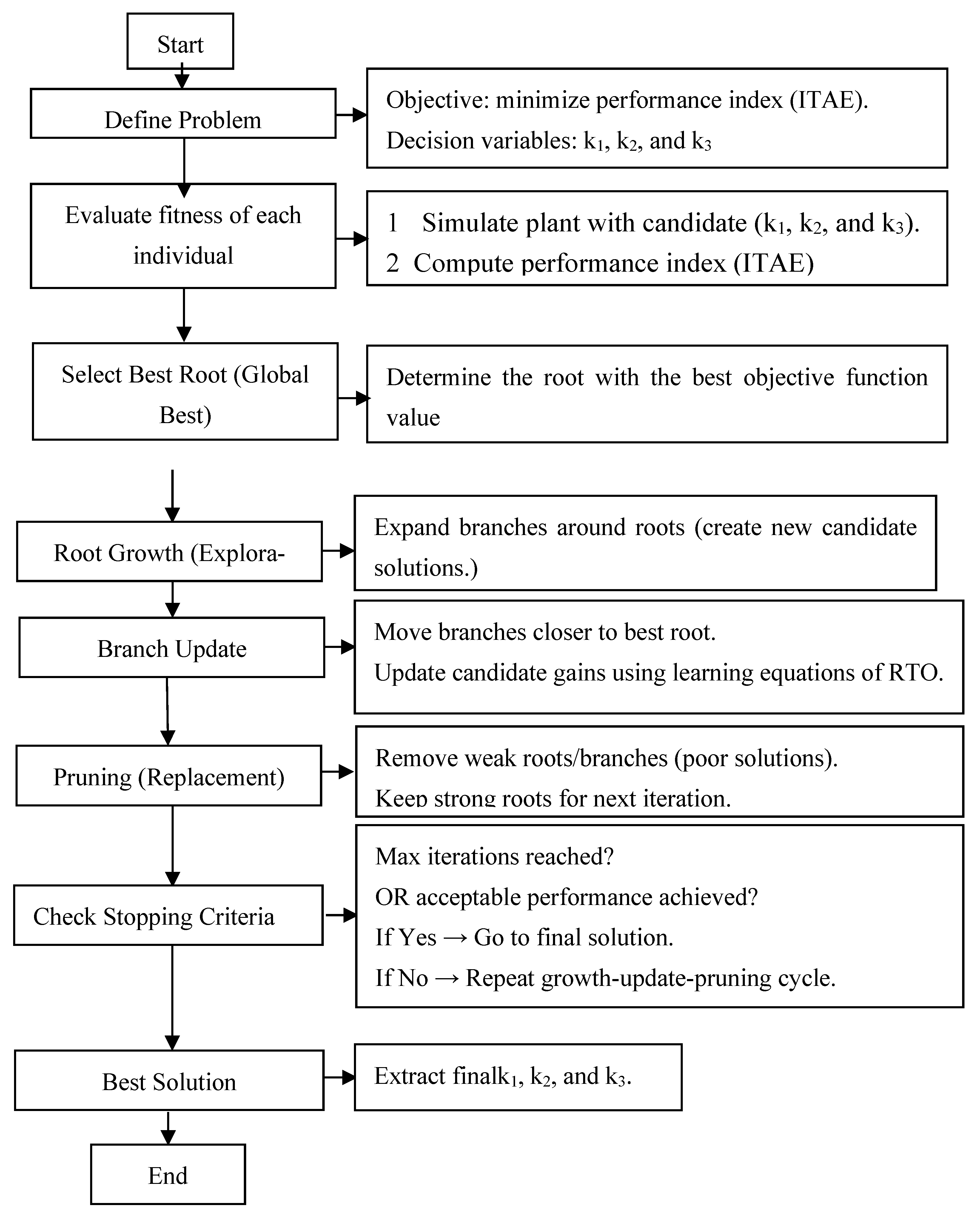
The values of the designed regulator are initially calculated using a GA. The utilization of the aforementioned algorithm is illustrated in the flowchart presented in Figure 2.
The RTO algorithm is employed in this study to estimate the gain values of the PII2 regulator, as illustrated in Figure 3.
To study the stability of this designed regulator, Lyapunov’s theorem can be used. In this work, Lyapunov’s analysis focuses on establishing the mathematical stability of the designed strategy, particularly with regard to the internal dynamics of electrical subsystems and control systems. This encompasses the assurance of the convergence of control errors and the boundary of the designed strategy’s outputs under the prescribed conditions. However, it has been acknowledged that the stability analysis that has been conducted does not take into account the fluid dynamic behavior of an MRT system. This behavior includes aerodynamic coupling between rotors, wake interactions, and unsteady fluid interactions with the structure. It should be noted that these phenomena are inherently nonlinear and subject to higher-order partial differential equations. These equations lie outside the scope of the control model. There are four main stages to prove and study the stability of this regulator.
Stage 1: Define the system.
In this stage, x1(t) = e(t) and x2(t) = ʃe(t).dt.
Equation (11) is written as follows:
u t = K 1 · x 1 + K 2 · x 2 + K 3 · x 2 2
Assuming that the controlled system is a simple first-order system, Equation (13) can be written as:
y ˙ t = u ( t )
Assuming that the reference value is zero (r(t) = 0), then in this case the following can be written as:
y t = e t
e ˙ t u t = y ˙ t
Then,
x ˙ 1 = u t = k 1 x 1 k 2 x 2 k 3 x 2 2
x ˙ 2 = x 1
From Equations (16) and (17) the nonlinear independent system can be written as represented in Equation (18).
x ˙ 1 = k 1 x 1 k 2 x 2 k 3 x 2 2 x ˙ 2 = x 1
Step 2: Choosing the Lyapunov Function
The Lyapunov function is chosen to prove the stability of the controller suggested as shown in Equation (19).
V x = 1 2 x 1 2 + 1 2 x 2 2
Equation (19) is positive (V(x) > 0) if x is different from zero and V(0) = 0.
Step 3: Calculate the derivative of a Lyapunov function.
The derivation of Equation (19) is written as follows:
V ˙ = x ˙ 1 x 1 + x ˙ 2 x 2
Using Equations (16) and (17) in Equation (20), Equation (21) can be written as:
V ˙ = ( k 1 x 1 k 2 x 2 k 3 x 2 2 ) x 1 + x 1 x 2
After completing the necessary simplifications, Equation (21) becomes as follows:
V ˙ = k 1 x 1 2 k 2 x 2 x 1 k 3 x 2 2 x 1 + x 2 x 1
Finally, the derivative of the Lyapunov function can be written according to Equation (22).
V ˙ = k 1 x 1 2 + ( k 2 k 3 + 1 ) x 2 x 1
Step 4: Extract stability conditions
To extract a stability condition, Equation (23) is used for this purpose.
The stability condition according to Lyapunov’s theorem is that the condition V ˙ must be less than or equal to 0, and therefore, Equation (23) is written as follows:
k 1 x 1 2 + ( k 2 k 3 + 1 ) x 2 x 1 0
To ensure stability,the positive term ( k 2 k 3 + 1 ) x 2 x 1 it must be controlled by the specified negative term k 1 x 1 2 .
Both k1 and k3 are assumed to be greater than 0 and k 2 1 .
Then,
If x 2 < 0 : ( k 2 k 3 x 2 + 1 ) > 0 , but x 2 < 0 , so again the ter mis negative.
If x 2 > 0 : ( k 2 k 3 x 2 + 1 ) < 0 , but x 2 < 0 producte negative.
Therefore, under these conditions, the derivative of the Lyapunov function is negative ( V ˙ 0 ) and the suggested regulator is stable.
In the case of asymptotic stability, V ˙ < 0 for al x 0 . In this case, Equation (25) can be written as follows.
( k 2 k 3 x 2 + 1 ) x 2 x 1 γ x 2 2
Equation (25) is true if γ takes small values. Therefore, the cross-cutting term is dominated by k 1 x 1 2 .
Therefore, for asymptotic stability, it is sufficient that the condition listed in Equation (26) is satisfied.
k 1 x 1 2 + ( k 2 k 3 x 2 + 1 ) x 2 x 1 < 0         x 0
The condition included in Equation (26) is satisfied if k1 is larhe enough, k 3 > 0 and k 2 0 .
Although the Lyapunov stability proof validates the mathematical robustness of the designed strategy under nominal conditions, it does not extend to encompass the aerodynamic stability of the entire MRT system. To comprehensively evaluate system-wide robustness, particularly in scenarios involving fluid-induced turbulence or wake interactions, further integration with aerodynamic or fluid–structure models is imperative.
Table 3 provides a comparative analysis of the designed controller and various linear and nonlinear controllers. In comparison with conventional PI and PID controllers, the PII2 controller outlined in this study introduces a secondary complementary concept, thereby facilitating enhanced performance in systems characterized by high-level dynamics, such as grid-connected inverters or electric motors. PI controllers are characterized by their ease of implementation; however, they frequently exhibit SSEs in the presence of load disturbances. The PII2 regulator has been demonstrated to offer enhanced tracking performance without reliance on derivative action, thereby circumventing the inherent noise sensitivity that is characteristic of PID controllers. In comparison with nonlinear controllers, such as SMC or synergetic control, the PII2 regulator offers a continuous and smooth control law. This characteristic renders it well-suited for applications where oscillation is undesirable. Despite its inability to provide the same degree of predictive capability as an MPC, it does offer a practical balance between performance and implementation complexity. The PII2 intelligent algorithm-based regulator has been demonstrated to be a suitable solution to overcome the drawbacks of the DPC strategy of DFIG. The PII2 algorithm has been shown to be more simple, more high-performing, and easier to implement than many other controllers.
The implementation of this designed regulator in a DFIG-based system has been demonstrated to enhance PQ and minimize THD. The subsequent section will provide a comprehensive discussion on the implementation of power control utilizing the designed regulator.

2.3. New DPC-PWM Technique

The strategy delineated in this section deviates from the conventional technique. The proposed DPC is designed to augment the conventional DPC by incorporating additional components and processes.
  • The elimination of hysteresis comparators is imperative.
  • The provision of a smoother command is accompanied by lower current and energy fluctuations.
  • The utilization of the PWM technique is contingent upon a constant switching frequency.
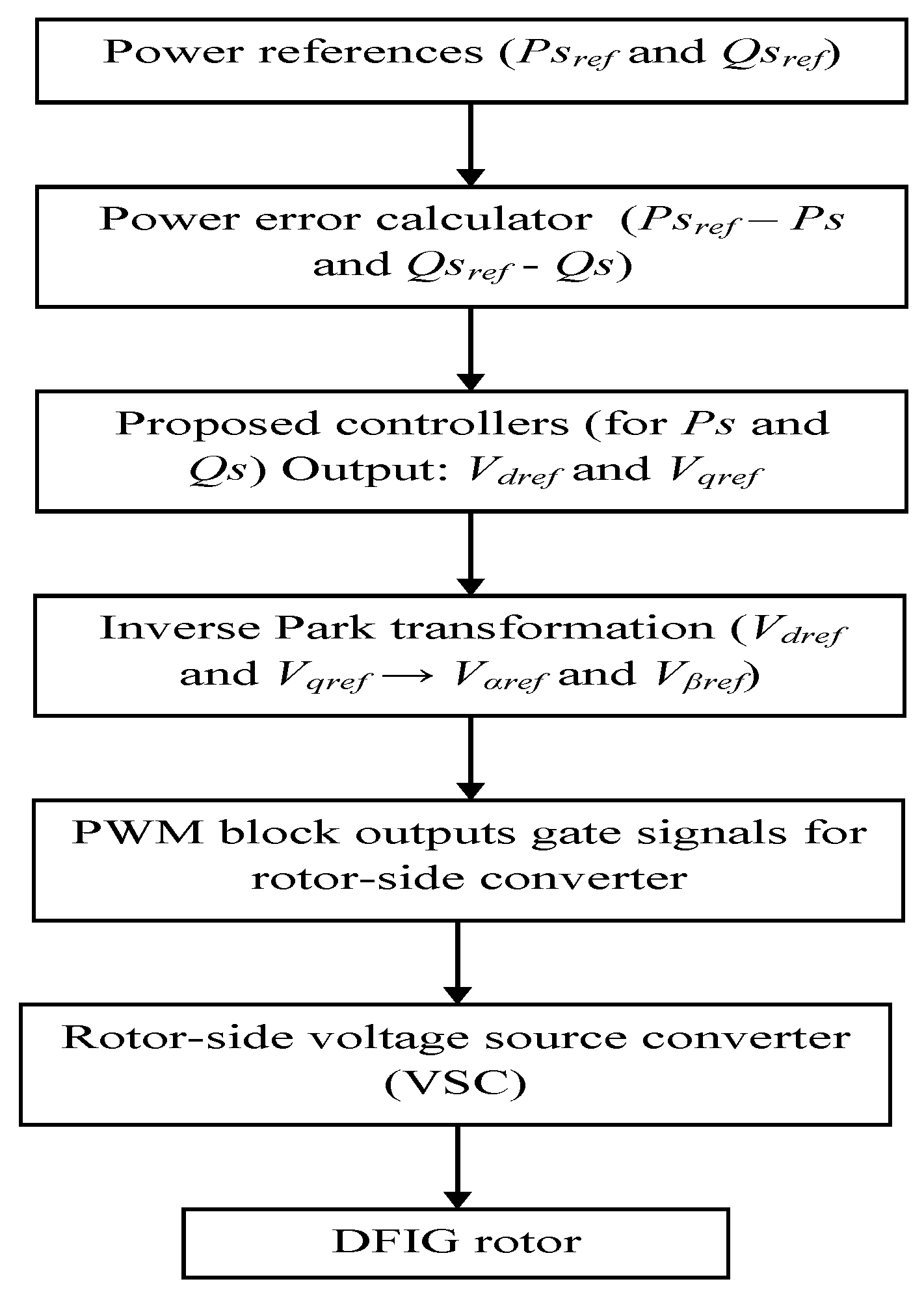
In this methodical approach, the following feedback signals are utilized: stator voltage and current to calculate DFIG power. In this designed approach, the rotor position (θ) is not utilized, thereby eliminating Park/reverse Park transformations. As illustrated in Figure 4, the designer’s approach is delineated in the form of a block diagram.
This strategy has several advantages over the traditional technique, the most prominent of which are low current/power ripple, fast dynamic performance, and high durability.
These improvements aim to address key DPC limitations, such as:
  • Parameter sensitivity.
  • Variable switching frequency.
  • Poor performance under faults or at low speed.
  • Flux estimation errors.
Nonetheless, the majority of these enhancements are accompanied by an increase in complexity, computational demand, or stability challenges.
To implement the previously outlined approach, it is necessary to measure the rotor current, stator voltage, and determine the reference value for the active and reactive power.
The strategy outlined in this paper is implemented to regulate the machine inverter exclusively, thereby evidencing its effectiveness in enhancing PQ and current THD without necessitating the control of the grid inverter or the utilization of active filters. Additionally, reliance on machine inverter control results in a reduction in system complexity and, consequently, a decrease in the cost of experimental implementation.
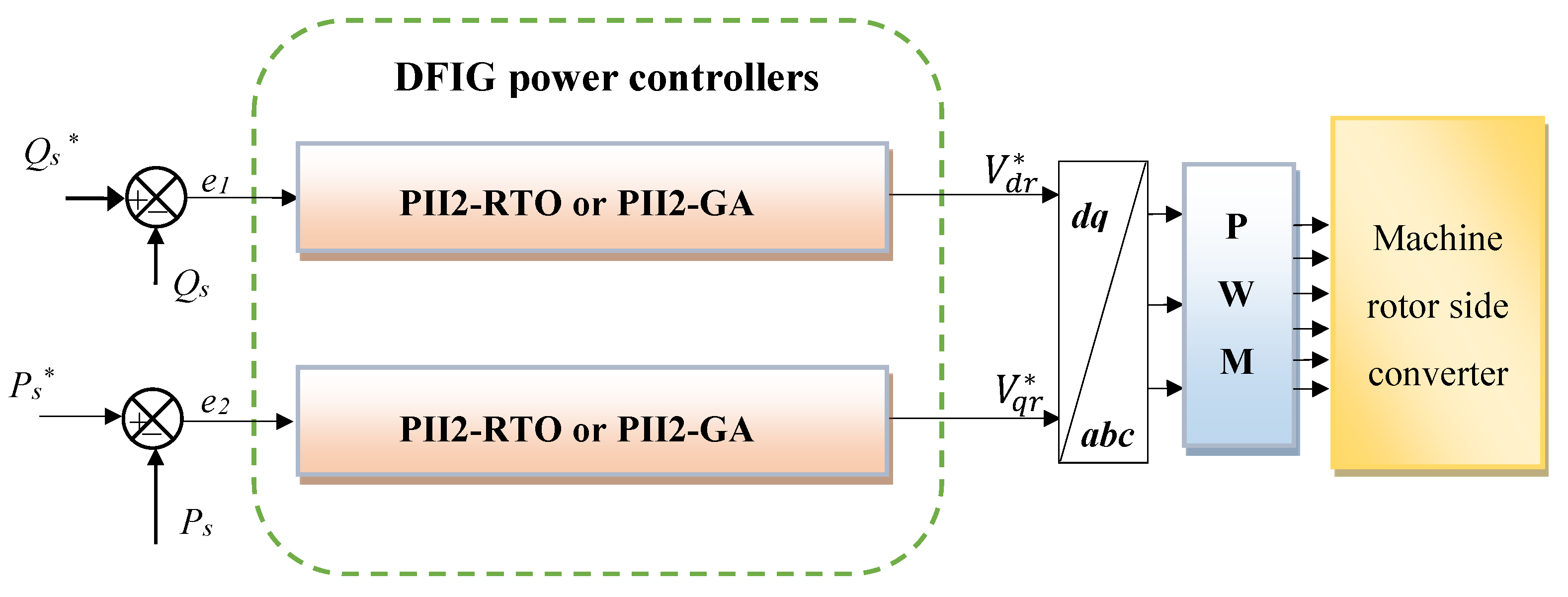
Figure 5 presents the block diagram of the designed DFIG power control. The approach is characterized by simplicity, ease of configuration, low complexity, and ease of application. Moreover, the absence of reliance on a mathematical model of the system under study guarantees satisfactory outcomes even in cases of altered generator parameters. This method of machine control involves the implementation of a PWM algorithm to regulate the machine’s inverter, diverging from conventional algorithms and those documented in the extant literature. PWM was selected on the basis of its simplicity and cost-effectiveness.
The reference value for reactive power is set to 0 to obtain a power factor of 1. Conversely, the reference value of active power is determined using the MPPT-PI strategy. The MPPT-PI method is adopted due to its ease of realization, simplicity, low complexity, and lower costs. The utilization of the MPPT-PI method establishes a correlation between the fluctuations in current and active power with those in WS.
This designed technique relies on power estimation to determine power errors. The power errors are used as input to the design regulator, which then generates reference values for the rotor voltage. One regulator is used to control the active power and another to control the reactive power.
To estimate the powers, the flux is first estimated. The same flux estimation equation used in the usual algorithm is used, where Equation (27) is used for this purpose [55].
ψ r β = 0 t ( V r R r × i r β ) d t ψ r α = 0 t ( V r R r × i r α ) d t
In this designed approach, the stator flux estimate is also used. This flux is estimated using Equation (28).
ψ s β = 0 t ( V s R s × i s β ) d t ψ s α = 0 t ( V s R s × i s α ) d t
The flux estimation employed in this study is predicated on constant electromagnetic parameters; however, it is conceivable that these parameters may not hold under conditions of instantaneously unstable flux, a scenario that has the potential to induce pressure-driven structural or thermal changes in the generator. In order to guarantee precise regulation in such circumstances, subsequent endeavors must integrate adaptive estimation techniques or observer-based flux estimators that dynamically compensate for parameter uncertainty.
According to the work done in [56], the powers are estimated using Equations (29) and (30). These equations are used to estimate the power error.
P s = 3 2 V s × ψ r β × L m σ × L r × L s
Q s = 3 2 V s σ × L s × ψ β r V s × L m σ × L r × L s × ψ α r
With,
σ = 1 M 2 L s L r
The strategy is predicated on the calculation of the power error. Two lines are of particular relevance: the active power error and the reactive power error. This discrepancy signifies the disparity between the reference value and the estimated value. Equation (32) provides a representation of the power error associated with the designer’s approach.
e 2 = P s P s e 1 = Q s Q s
where e1 is the reactive power error and e2 is the active power error.
The determination of reference values for the rotor voltage is contingent upon the calculation of the power error. The reference values are expressed in Equation (33). Equation (33) is representative of the fundamental principle of the strategy that was meticulously designed in this paper.
V d r = K 1 · e 1 + K 2 · e 1 d t + K 3 · ( e 1 d t ) 2 V q r = K 4 · e 2 + K 5 · e 2 d t + K 6 · ( e 2 d t ) 2
Here, e1 is the reactive power error, V q r is the reference of the quadrature rotor voltage, e2 is the active power error and V d r is the reference of the direct rotor voltage.
Table 4 compares the new algorithm with techniques such as SMC-DPC and neural DPC. The designed strategy demonstrates superior performance in terms of its dynamic response speed and power fluctuation stability when compared with DTC and SMC-DPC. In comparison with conventional methodologies, the designed strategy demonstrates a reduced susceptibility to alterations in machine parameters, rendering it well-suited for control applications. The novel technique exhibits a reduced computational complexity in comparison to both neural DPC and SMC-DPC, yet it is more intricate than the classical algorithm. In the case of the designed algorithm, the degree of sensor dependence is lower in comparison to both the traditional algorithm and SMC-DPC. In summary, the novel algorithm preserves the simplicity and ease of application that are hallmarks of the conventional method in comparison to SMC-DPC and neural DPC. In addition, it is more straightforward to make adjustments and does not depend on the mathematical model of the system under study when compared to SMC-DPC.

3. Results

The new algorithms are realized using MATLAB software with the specified parameters of the used DFIG: Rr = 0.021 Ω, Lr = 0.0136 H, Vs = 398 V, Pn = 1.5 MW, Rs = 0.012 Ω, f = 0.0024 Nm/rad.s−1, fs = 50 Hz, Ls = 0.0137 H, p = 2, M = 0.0135 H, J = 1000 Kg.m2.
The system implemented in MATLAB is represented in Figure 6. In this study, three distinct strategies are implemented in MATLAB and subsequently compared with each other under both normal and abnormal operating conditions. The implemented strategies are DPC-PI, DPC-PII2-RTO, and DPC-PII2-GA.
In order to accomplish the objectives of the research study, two distinct simulation tests were conducted. The initial test was the reference tracking test under normal conditions, while the second test was designed to identify the presence of a defect in the system under study (parameter change). These tests were utilized to facilitate a comparison of the proposed algorithms. These tests involve assessing various aspects, including energy fluctuations, THD value of one phase stator current (ias), ITAE, torque fluctuation ratios, Qs and Ps overshoot ratios, SSE, and so on.
The present study was conducted and implemented under a range of operating conditions, with the objective of emphasizing the primary contributions. These contributions include the development and adoption of an efficient DPC method, in conjunction with PWM, for the purpose of active power regulation. The aerodynamic interaction model is not within the scope of the present work, which is chiefly concerned with the electrical and control aspects of the system. Consequently, subsequent research endeavors will be initiated to assess the resilience of the proposed DPC-PWM scheme, underpinned by intelligent controllers, in the context of realistic flow interference scenarios.

3.1. The First Test

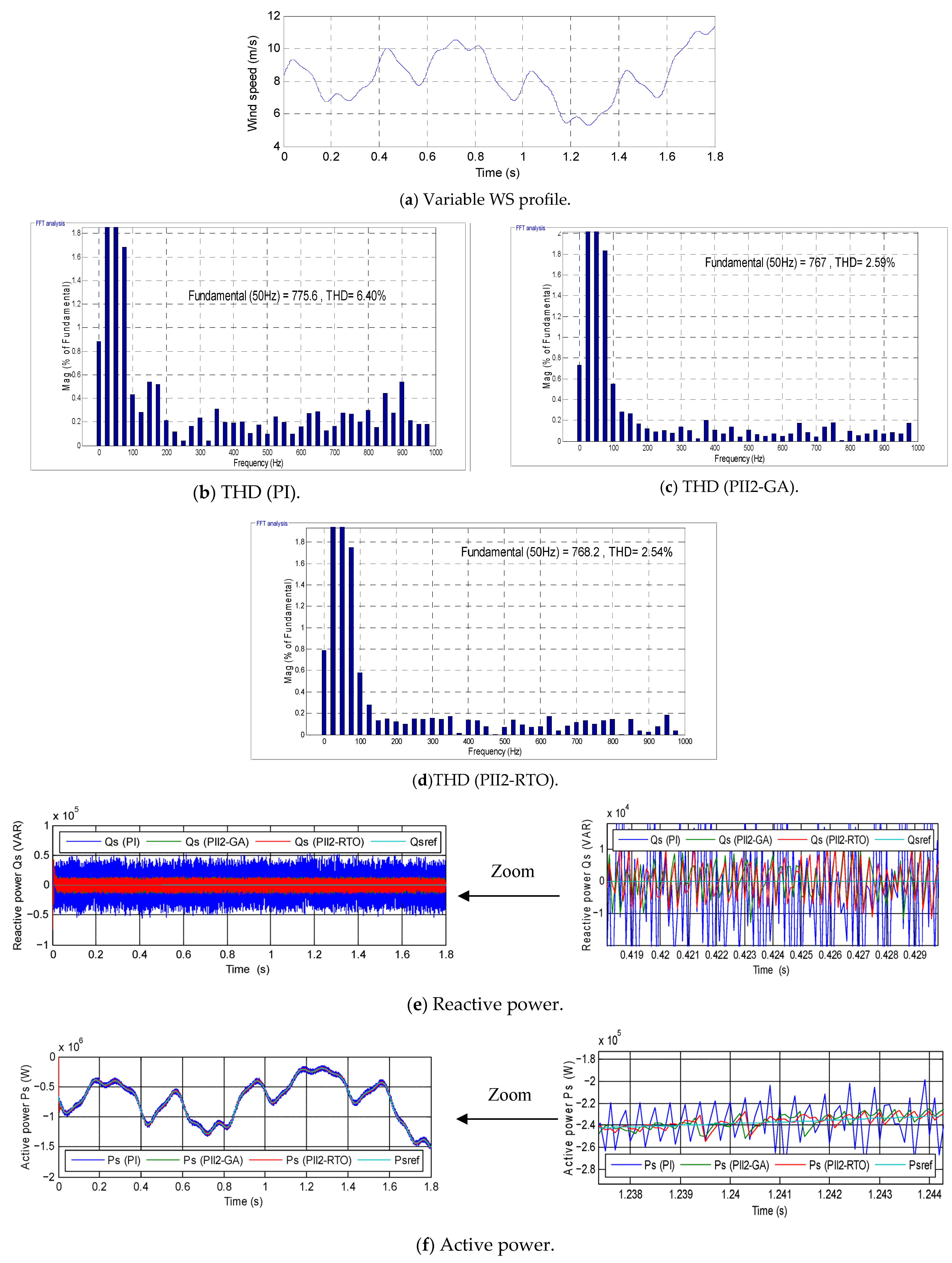
The efficacy of the algorithms developed in this study is initially validated under standard conditions, with a comparison of performance metrics against a PI-based strategy. The utilization of variable WSs is illustrated in Figure 7a. The results of this test are presented in Figure 7 and Table 5.
As illustrated in Figure 7b–d, the THD of current is represented for the three commands implemented in this study. In the conventional approach, the THD value was estimated to be 6.40%. In the PII2-GA, the THD value was 2.59%, while in the PII2-RTO, the THD value was 2.54%. The findings suggest that the PII2-RTO approach produced notably superior THD values in comparison to alternative strategies. Consequently, the PII2-RTO diminished the THD value by 60.31% and 1.93% in comparison to the conventional approach and PII2-GA, respectively. Furthermore, the PII2-GA approach led to a 59.53% reduction in THD values when compared to the conventional algorithm. Consequently, it can be posited that the implementation of intelligent algorithms leads to a substantial enhancement in the THD value when contrasted with conventional methodologies. However, the findings indicate the efficacy of the PII2-RTO approach in improving the current quality in comparison to PII2-GA, thereby substantiating its potential as a promising solution.
Figure 7e, fillustrate the variations in both reactive and active power in this test for two controllers. The power values in question align closely with established references, with the active power manifesting as alterations in WS and a swift dynamic response. It is also imperative to acknowledge that the power values are negative, which signifies that the system is operating in a power generation mode. However, it should be noted that the reactive power remains constant in the face of variations in WS. In the presence of undulations, this power remains zero. As indicated by the data presented in Table 5, the power undulations exhibited by the PII2-RTO are notably lower in comparison to those observed in the other strategic approaches. The PII2-RTO approach demonstrated a significant reduction in active power undulations, with an 81.88% decrease compared to the PI approach and a 51.92% decrease compared to the PII2-GA approach. Furthermore, the PI approach demonstrated a 77.94% reduction in reactive power undulations when compared to the proposed method. In comparison with the PI, the PII2-GA demonstrated a significant reduction in active and reactive power fluctuations, with percentages of 62.31% and 79.51%, respectively. In addition, the PII2-GA approach led to a 7.14% reduction in reactive power ripples compared to the PII2-RTO. Consequently, the smart strategies exhibited a reduced impact compared to the PI. As illustrated in Table 4, there appears to be a certain degree of similarity between the results obtained through the utilization of both the GA and RTO regulators.
As illustrated in Table 5, the SSE of power demonstrates superiority for the PII2-GA and PII2-RTO strategies in comparison to the PI regulator. However, PII2-RTO exhibited suboptimal SSE values in comparison to PII2-GA. Therefore, the PII2-RTO approach demonstrated a significant reduction in active and reactive power SSE, with percentages of 74.48% and 69.16%, respectively, in comparison to the PI regulator. As illustrated in Table 5, the PII2-GA approach led to a substantial reduction in active power SSE, with percentages of 96.55% and 86.48%, respectively, when compared to the PI and PII2-RTO methods. In the context of reactive power, the PII2-GA approach led to a significant reduction in the SSE by 81.53% and 40.31%, respectively, when compared to the PI and PII2-RTO methods. In the case of active power overshoot, strategies PII2-RTO and PII2-GA yielded unsatisfactory values compared to the PI, as shown in Table 5. Consequently, the overshoot value can be regarded as a concern associated with the strategies outlined in this paper. This deficiency can be ascribed to the gain values. This limitation may be addressed in the future through the implementation of alternative strategies. Conversely, as illustrated in Table 4, the PII2-RTO approach resulted in suboptimal values for power overshoot in comparison to the PII2-GA method. The PII2-GA reduced the overshoot value by 9.62% and 51.93% points for both active and reactive power, respectively, compared to PII2-RTO. As illustrated in Table 5, the PI regulator demonstrates a marked superiority in terms of power response time when compared to alternative regulators. Therefore, the power response time is a disadvantage of the smart strategies designed in this paper. A comparison of the PII2-GA strategy and the PII2-RTO strategy reveals that the former results in an enhancement of 0.5% in active power response time.
The ITAE value for active power in this test is significantly lower for the PII2-GA compared to the other algorithms. As illustrated in Table 5, the PII2-RTO approach led to a 68.19% reduction in the ITAE compared to the PI. In addition, the PII2-GA approach led to a 68.30% and 0.33% reduction in ITAE compared to PI and PII2-RTO, respectively. The findings indicate that the GA exhibits superior efficiency in comparison to the RTO algorithm, thereby substantiating its reliability as a control solution.
Figure 7g, hillustrate the variations in both current and torque in the initial test case for the designed regulators. It is imperative to acknowledge the variability of these values in response to alterations in WS and the occurrence of fluctuations. The utilization of smart algorithms has been demonstrated to result in a substantial reduction in both current and torque ripples in comparison to the PI regulator. It is also noteworthy that the torque exhibits negative values, suggesting that the system is generating power. It has been observed that the current exhibited by the designed algorithms assumes a sinusoidal form with a periodicity of 0.02 s.

3.2. The Second Test

The three strategies outlined in this paper are evaluated in this experiment, with varied the generator parameters. The inductance values are multiplied by 0.5, while the resistance values are multiplied by 2. The same WS as in the initial experiment is employed. Figure 8 presents the graphical results of this experiment using the three strategies. Table 6 presents the numerical values obtained with the reduction ratios.
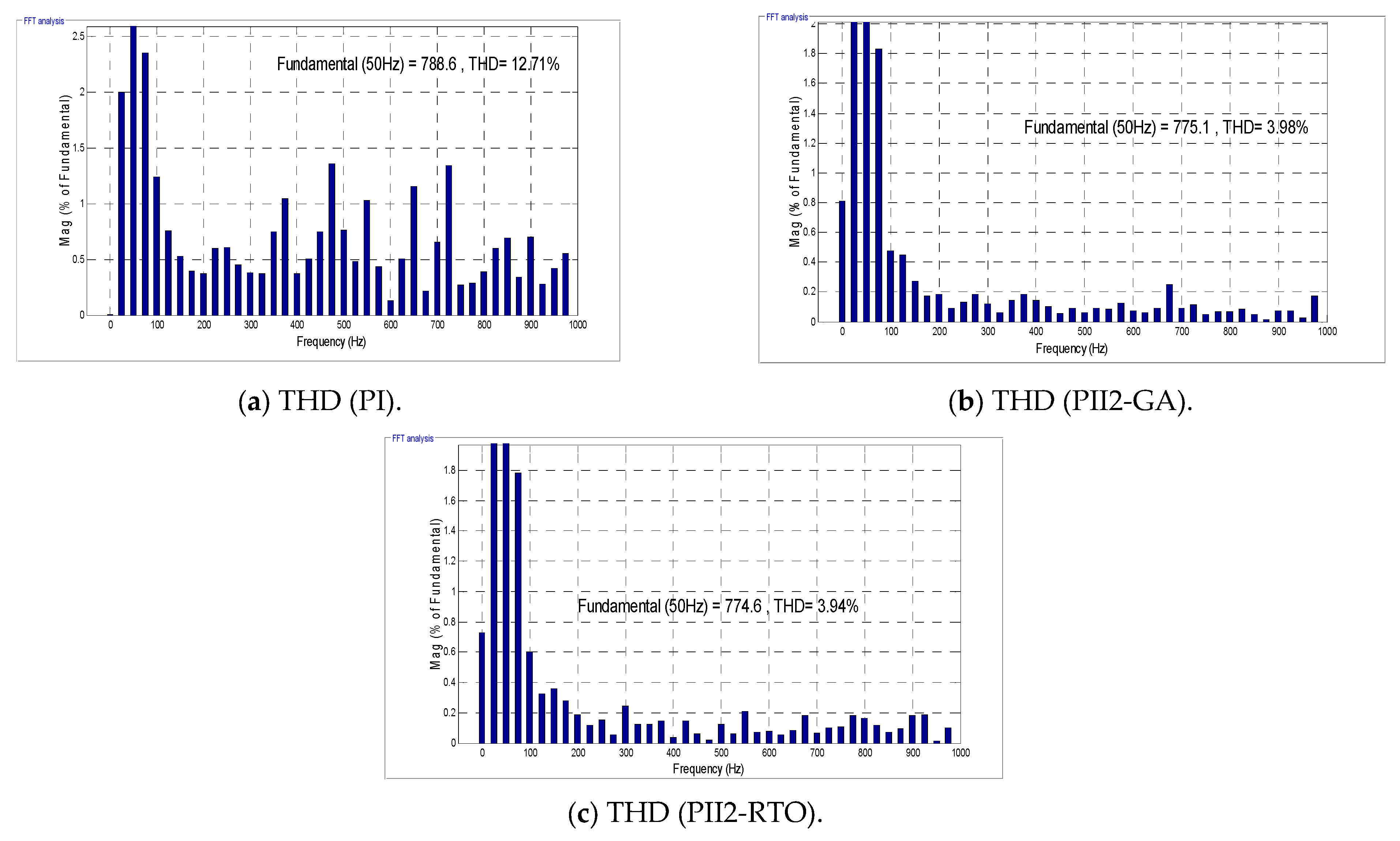
As illustrated in Figure 8a–c, the THD of current values for the three algorithms is represented. A comparison of these figures with the results of Test 1 reveals an increase in the THD value. This finding indicates that the THD value is influenced by alterations in machine parameters. This effect is more pronounced when using the PI regulator in comparison to alternative regulators.
In this test, the THD values were estimated to be 12.71%, 3.98%, and 3.94%, respectively, for PI, PII2-GA, and PII2-RTO. It has been demonstrated that PII2-GA and PII2-RTO yielded nearly equivalent THD values. This finding suggests that the performance of the RTO and GAsis largely analogous. The PII2-RTO approach demonstrated a 69% and 1% reduction in THD compared to PI and PII2-GA, respectively. The PII2-GA strategy demonstrated a 68.68% reduction in THD when compared to the PI regulator. These findings indicate that the implementation of PII2-RTO and PII2-GA regulators results in a substantial enhancement of current quality, thereby substantiating their reliability as effective solutions.
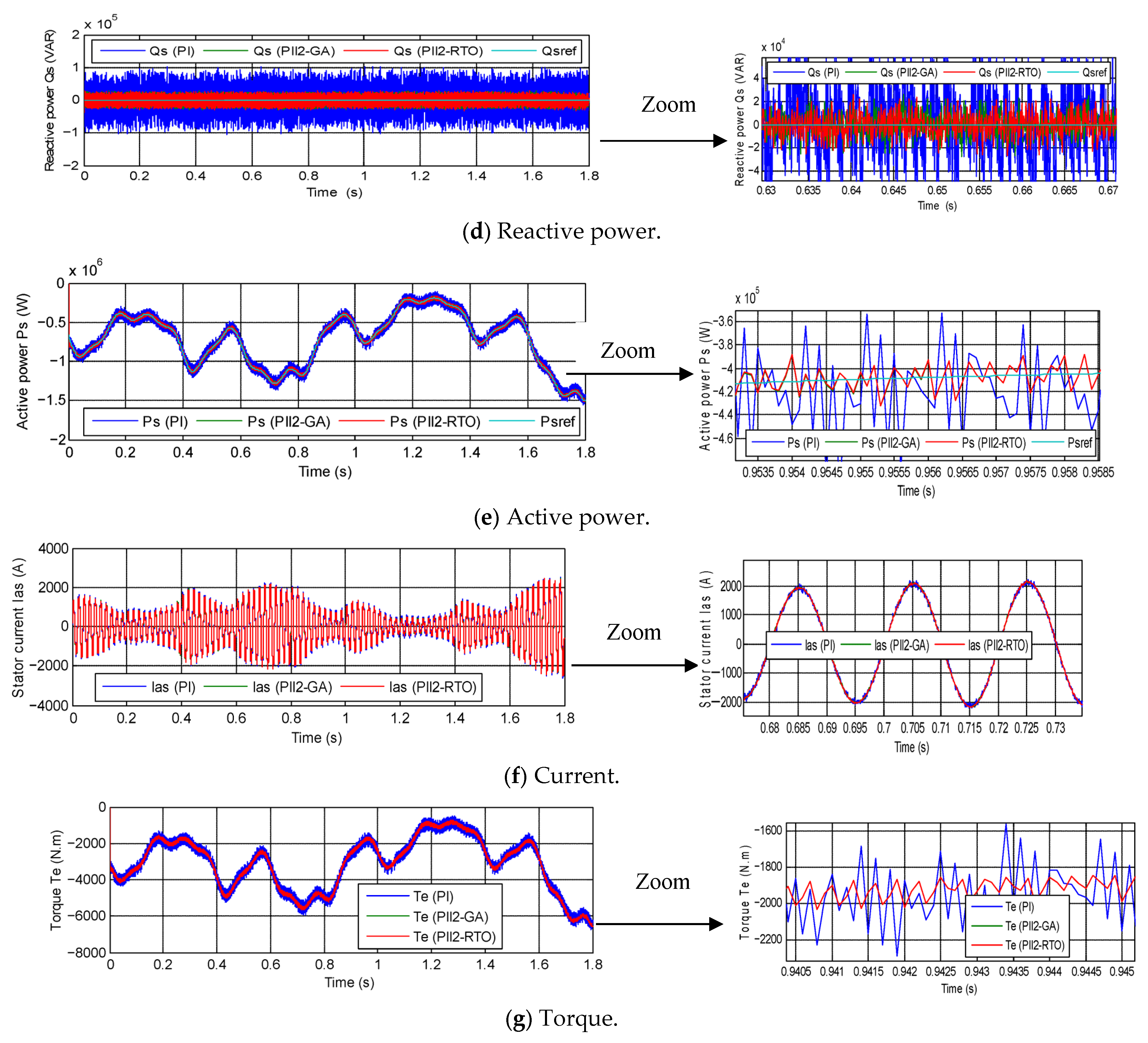
Figure 8d, eillustrate the power outputs for the three controls as the machine parameters undergo variation. The characteristics of these power outputs are enumerated in Table 6. As illustrated in Figure 8d,e, despite the alterations in the generator parameters, the power outputs demonstrate a close adherence to the reference values, exhibiting fluctuations. It has been demonstrated that the active power undergoes fluctuations in accordance with alterations in WS. Conversely, the reactive power exhibits a consistent pattern throughout the duration of the simulation. A comparison of the values listed in Table 6 with those in Table 5 reveals that the values of fluctuations, response time, ITAE, SSE, and overshoot of DFIG power were significantly affected by changes in generator parameters. This effect is more pronounced in the case of using the PI regulator compared to the PII2-RTO and PII2-GA regulators.
As indicated by the findings presented in Table 6, power fluctuations are considerably less pronounced when employing the PII2-RTO regulator in comparison to alternative regulators. The PII2-RTO and PII2-GA regulators demonstrated a 75% reduction in reactive power ripple in comparison with the PI regulator. Concurrently, the PII2-RTO regulator generated ripples of equivalent magnitude to those produced by the PII2-GA regulator, suggesting analogous performance characteristics. In comparison with the PI regulator, active power ripples were reduced by 72.72% with the PII2-RTO and by 79.12% with the PII2-GA regulator. In comparison with the PII2-RTO, the active power ripple is reduced by 23.46% with the PII2-GA. The ratio under consideration serves as an indicator of the effectiveness of the GA in comparison to the RTO with respect to the enhancement of active power ripple characteristics, notwithstanding alterations in machine parameters.
As demonstrated in Table 6, the SSE of DFIG power is notably lower for PII2-RTO and PII2-GA regulators in comparison to PI regulators. A comparison of the SSE of active power reveals that it is 64.16% and 88.88% lower for PII2-RTO and PII2-GA, respectively, when compared to PI regulators. The SSE of reactive power is 80% and 85% lower for PII2-RTO and PII2-GA, respectively.
The PII2-GA regulator demonstrated superior SSE values in comparison to the PII2-RTO, exhibiting a reduction in active and reactive power of 68.99% and 25%, respectively. These results also demonstrate the effectiveness of the GA compared to the RTO, despite the change in DFIG parameters.
As illustrated in Table 6, the utilization of the PII2-RTO and PII2-GA strategies results in a reduction in the excess reactive power value by approximately 76.03% in comparison to the PI regulator. It has been observed that the PII2-RTO regulator exhibited a reactive overshoot value that was equivalent to that of the PII2-GA regulator. However, in terms of the active overshoot value, the PII2-RTO and PII2-GA regulators demonstrated suboptimal performance in this test when compared to the PI regulator. Consequently, the active overshoot value is identified as a disadvantage of the PII2-GA and PII2-RTO regulators in this particular test. The prospect of overcoming this disadvantage in the future is promising, and the utilization of fuzzy logic in this regard holds particular promise.
A comparison of the PII2-GA and PII2-RTO regulators revealed that the former exhibited a 25% higher active power overshoot. This outcome suggests that the GA is more effective in enhancing the overshoot value when compared to the RTO algorithm.
The power response time in this test is significantly lower with the PI regulator compared to both the PII2-GA and PII2-RTO, as shown in Table 6. The PII2-RTO regulator gave a power response time equal to that provided by the PII2-GA regulator. In this test, the response time to the power can also be considered a negative for the PII2-RTO and PII2-GA. This negative can also be attributed to the gain values, which can be overcome in the future using the fractional calculus strategy.
Figure 8f,g represent the variations in torque and current in this test of the two algorithms. These figures show that torque and current are affected by changes in generator parameters, as evidenced by the increased ripples for the three controls. Torque and current ripples are very similar for the PII-RTO and PII2-GA regulators. However, these ripples are significantly higher when using a PI, indicating that this algorithm is more affected by changes in DFIG parameters than other controllers. Furthermore, despite the changes in generator parameters, the shape of the torque and current changes with WS, with the torque remaining negative and the current taking a sinusoidal form with a period of 0.02 s for all three algorithms.

3.3. The Third Test

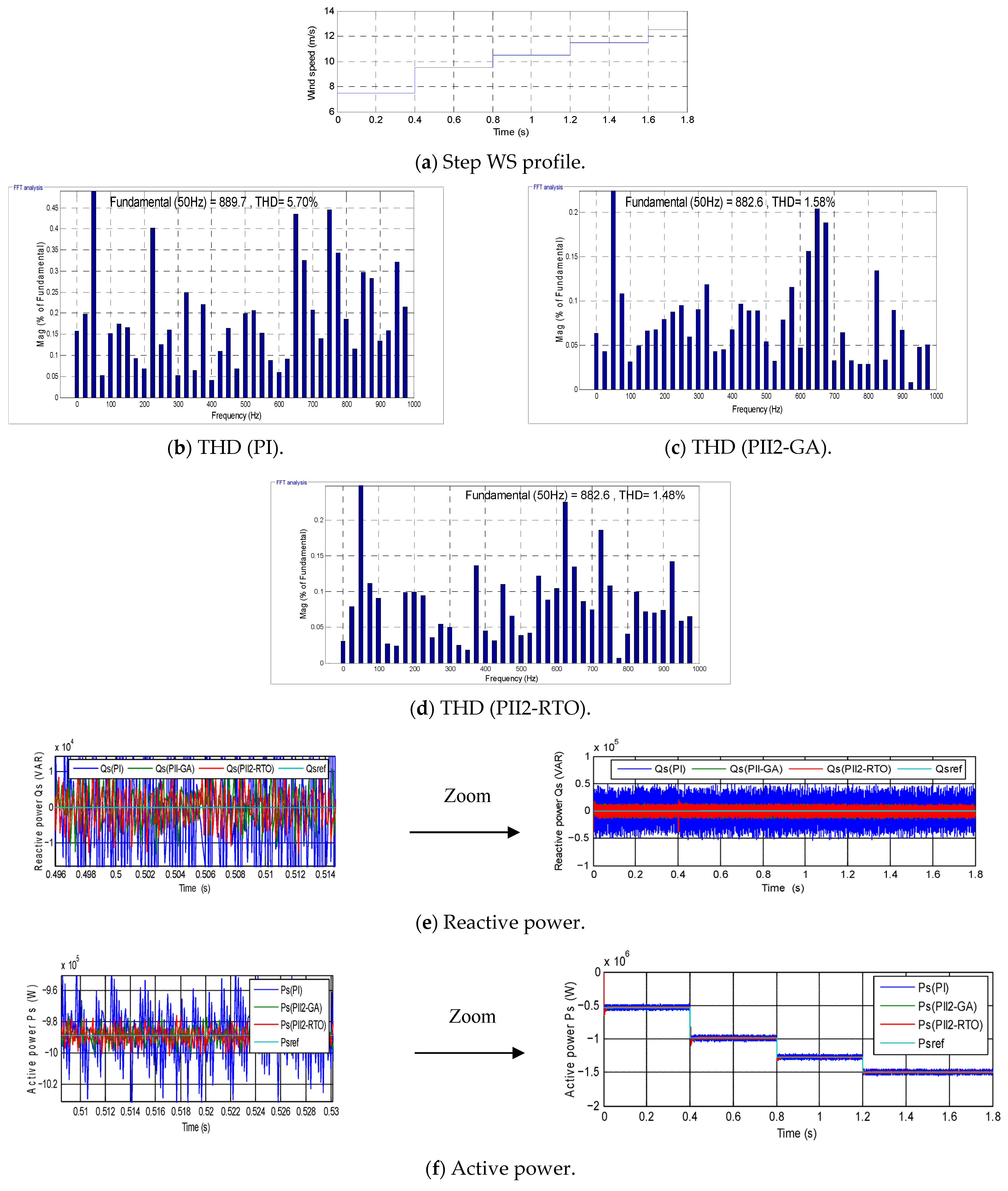
In this test, the designed approach is studied under a different WS than the one used in the initial test. The objective of this study is to assess the efficacy of the three strategies when employing a step WS profile. Figure 9a illustrates the WS variation profile employed in this investigation. The results obtained for the three controls are presented in Figure 9 and Table 7.
As illustrated in Figure 9b–d, the amplitude of the fundamental signal and the THD value of the current are represented. The THD values were determined to be 5.70%, 1.58%, and 1.48% for PI, PII2-GA, and PII2-RTO, respectively. The values obtained from this test indicate that the THD is significantly lower in this instance than in the previous tests for all three controls. This suggests that the pattern of WS variation has a significant impact on the THD value.
In this experiment, the THD value was found to be considerably lower when smart regulators were utilized in comparison to conventional regulators. In addition, the PII2-RTO regulator demonstrated a THD value that was 6.32% superior to that of the PII2-GA regulator.
A comparison of the PII2-RTO regulator with the PI regulator indicates that the former reduced the THD value by 74.03%. The ratio is indicative of the effectiveness and power of the PII2-RTO approach in improving current quality, thus indicating that it is a promising solution.
As illustrated in Figure 9b–d, the fundamental signal (50 Hz) amplitude in this test was 889.70 A with the PI regulator and 882.6 A with both PII2-RTO and PII2-GA. The results of this study suggest that the PI regulator exhibits a higher amplitude compared to the other regulators. Consequently, the amplitude in this test is regarded as negative for the PII2-RTO and PII2-GA regulators. This negative can be attributed to the gain values, which can be overcome in the future.
Figure 9e,f illustrate the power alterations for the three controls when employing step WS. As illustrated in Figure 9e, the reactive power remains constant despite the fluctuations in the three controls. In addition, the efficacy of this power remains constant in the presence of rapid fluctuations in WS for the three control mechanisms, thereby underscoring the insensitivity of the aforementioned strategies. Additionally, this power exhibited a rapid dynamic response, as evidenced in Table 7, wherein the PI regulator demonstrated superior response time in comparison to the other controllers. The PII2-RTO and PII2-GA regulators exhibited equivalent response times for the reactive power. As illustrated in Table 7, the ripple and SSE of the reactive power are notably superior for the PII2-RTO and PII2-GA regulators in comparison to the PI regulator. A comparison of the PII2-GA regulator and the PII2-RTO reveals that the ripple and SSE of reactive power are significantly reduced for the PII2-RTO. The PII2-RTO reduces the ripple by 22.65%, and it reduces the SSE by 5.66%.
As demonstrated in Table 7, the PII2-RTO and PII2-GA regulators exhibited suboptimal overshoot values in comparison to the PI regulator. Consequently, the overshoot value can be regarded as a negative for these regulators in this particular test. This negative outcome can be attributed to the optimal gain values, which can be overcome in the future. A comparison of the PII2-GA regulator with the PII2-RTO regulator reveals that the former attained a substantially superior reactive power overshoot value of 1.15%. The ratio indicates a clear superiority of the GA over the RTO algorithm.
As illustrated in Figure 9f, the variation in active power across the three controls is evident. This figure demonstrates that this power takes the form of changes in WS, with a rapid dynamic response when using all three controls. In addition, the active power remains in a negative state, with ripples observed across all three controls. According to Table 7, these ripples are lower when using the PII2-GA (71.61%) and PII2-RTO (87.67%) regulators compared to the PI regulator. The PII2-RTO regulator demonstrated a 56.56% reduction in active power ripples in comparison with the PII2-GA regulator.
As illustrated in Table 7, both the SSE and ITAE values are found to be significantly lower when employing the PII2-GA and PII2-RTO regulators in comparison to the PI regulator. The table indicates that the PII2-RTO regulator diminished both SSE and ITAE values by 60% and 62.85%, respectively, in comparison to the PI regulator. In addition, the PII2-GA regulator demonstrated superior performance in terms of SSE and ITAE values when compared to the PI regulator, exhibiting a 72.66% and 62.83% increase, respectively. In comparison with the PII2-GA regulator, the ITAE value was reduced by 0.06%. However, in terms of SSE value, the PII2-GA regulator demonstrated a significantly superior value of 31.66%, in comparison to the PII2-RTO.
In this experiment, the PII2-GA and PII2-RTO controllers exhibited substandard performance in terms of response time and active power overshoot when compared to the PI controller. Therefore, it can be concluded that these values are the drawbacks of the controllers in this test. With regard to active power response time, the PII2-GA and PII2-RTO controllers demonstrated analogous response times, suggesting comparable operational performance. However, in terms of the active power overshoot value, the PII2-GA regulator yielded a significantly superior value, estimated at 14.98%, compared to the PII2-RTO regulator. The findings of this study suggest a substantial performance disparity between the regulatory mechanisms outlined in this paper.
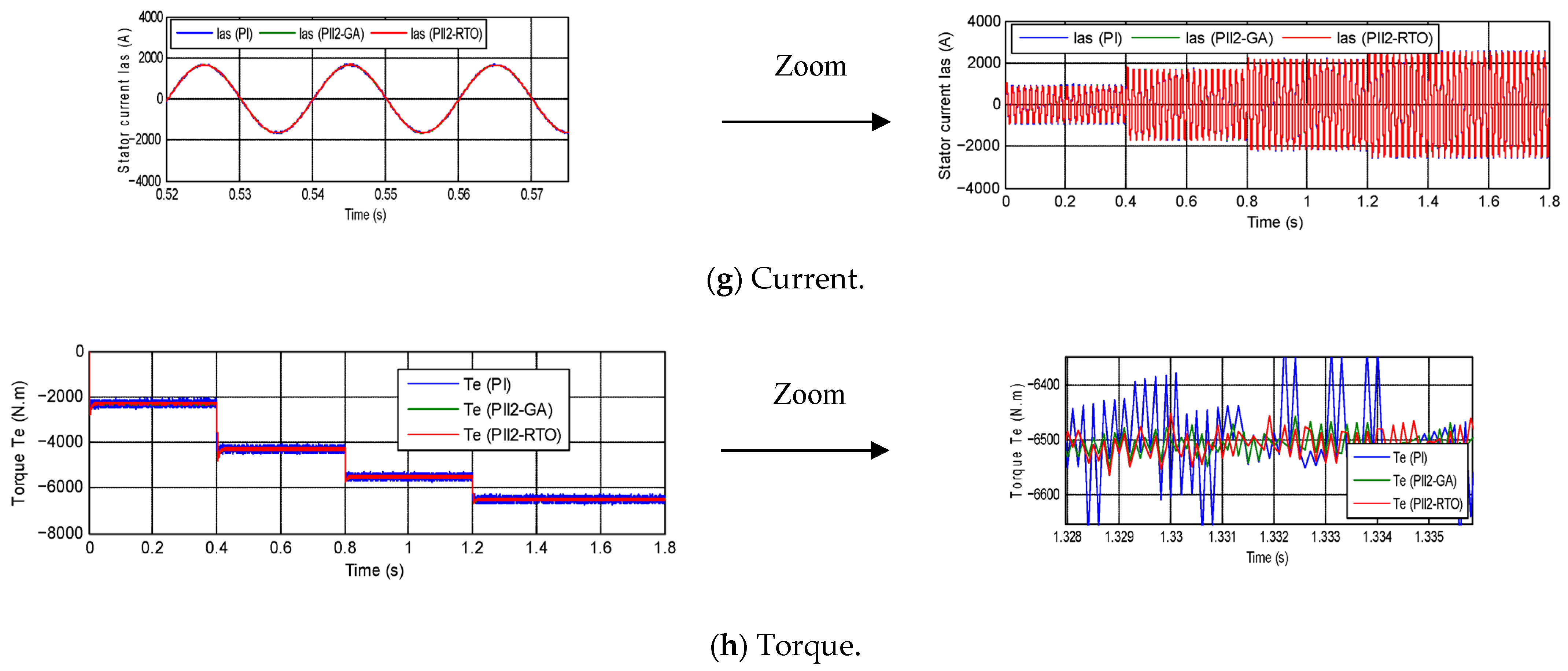
Figure 9g,h illustrate the variations in current and torque for the three controls as the wind speed as represented in Figure 9a. The figures demonstrate that the current and torque vary with the WS for the three controls, with undulations present. Furthermore, Figure 9g demonstrates that the current exhibits a sinusoidal pattern with a periodicity of 0.02 s for all control modalities, which is consistent with the preceding test results.
In this test, the ripple values were estimated at 80 A, 25 A, and 20 A for the PI, PII2-GA, and PII2-RTO, respectively. Therefore, the PII2-RTO regulator reduced the ripple values by 75% and 20%, respectively, compared to the PI and PII2-GA. The findings of this study suggest that the PII2-RTO regulator demonstrates superior efficacy in enhancing current quality in comparison to alternative regulators, thereby establishing it as a leading contender.
As illustrated in Figure 9h, the torque exhibits a negative component under all three controllers. This observation is consistent with the results reported in the preceding tests. Additionally, the torque demonstrates a rapid dynamic response, with the PI regulator exhibiting superior performance in comparison to other regulatory mechanisms. Torque ripples in this test were estimated to be 350 N⋅m, 89.15 N⋅m, and 70 N⋅m for the PI, PII2-GA, and PII2-RTO, respectively. These values underscore the efficacy of the PII2-RTO regulator in reducing torque ripple, a key advantage over competing regulators. In accordance with the experimental findings, the PII2-RTO regulator demonstrated a significant reduction in torque ripples, with a reported decrease of 80% and 21.48%, respectively, when compared to the PI and PII2-GA models.
Table 8 presents a statistical study of the ITAE of active power and THD of current values for the three controls. The following table presents the mean and standard deviation for the three controls. Additionally, the minimum and maximum values for each of the ITAE and THD for the three controls are obtained. As illustrated in Table 8, the maximum THD values were recorded as 12.71%, 3.98%, and 3.94% for PI, PII2-GA, and PII2-RTO, respectively. It is noteworthy that all three controls attained maximum THD values in the second test (robustness test). Consequently, the PI approach yielded the highest THD value. Furthermore, the maximum ITAE for active power was estimated to be 36,080 A, 10,510 A, and 10,580 A for PI, PII2-GA, and PII2-RTO, respectively. These values indicate that the PII2-GA regulator yielded a lower maximum value compared to the other strategies. It is also noteworthy that the maximum ITAE value for all three controls was observed in the second test.
The minimum THD value for the three controls was obtained in the third test. The PII2-RTO regulator demonstrated superior performance in this regard compared to the other regulators. The minimum ITAE value for the three controls demonstrated a superior performance with the PII2-GA regulator in comparison to the other regulators.
As illustrated in Table 8, the mean ITAE values were estimated to be 23,823.33 A, 7254.33 A, and 7593 A, respectively. These values indicate that the PII2-GA regulator produced a significantly lower mean ITAE than the other strategies.
The mean THD values were estimated to be 8.27%, 2.71%, and 2.65% for the PI, PII2-GA, and PII2-RTO, respectively. These values indicate that the PII2-RTO regulator achieved an average THD value that was 2.27% better than the PII2-GA regulator and 67.95% better than the PII2-GA regulator. Therefore, it can be concluded that the PII2-RTO regulator is more effective in improving current quality than other regulators. Nevertheless, with regard to the standard deviation of THD, the PII2-GA regulator demonstrated a marked superiority over the other regulators. As illustrated in Table 8, the standard deviations of THD were recorded to be 3.15%, 0.98%, and 1.02%, respectively, for the PI, PII2-GA, and PII2-RTO. In addition, the PII2-GA regulator demonstrated superior performance in terms of the standard deviation of ITAE (active power) when compared to other regulators. The standard deviations of active power (ITAE) were 8667.37 A, 2141.11 A, and 2145.76 A for the PI, PII2-GA, and PII2-RTO, respectively. Consequently, the standard deviation of ITAE was enhanced by 75.29% and 0.21%, respectively, when compared to PI and PII2-RTO. The findings of this study suggest a high degree of similarity in the performance of the PII2-GA and PII2-RTO regulators, which complicates the determination of the optimal regulator. Therefore, the performance of the RTO algorithm is comparable to that of the GA. However, the simplicity of the GA renders it a superior solution when compared to the RTO algorithm. The implementation of the RTO algorithm necessitates the development of a relatively sophisticated program, whereas the GA does not require such programming complexity. The utilization of the GA is facilitated by employing the gatool in MATLAB to ascertain optimal gain values.
Table 9 provides a comparative analysis of the algorithms developed in this paper with those from other sources with regard to THD current. The following table illustrates the efficacy of the algorithms in comparison to advanced strategies, demonstrating their superiority in reducing THD and, consequently, enhancing current quality. This comparison offers a clear depiction of the efficacy of the algorithms developed, particularly PII2-RTO, thereby substantiating their reliability as a solution in the energy sector. PII2-GA demonstrated a significant reduction in THD by 43.97%/86%, 46.92%/38.18%, 66.92%, 70.40%, 73.32%, 61.34%, and 78.41%/56.30%, respectively, when compared to the referenced studies [57,58,59,60,61,62,63]. PII2-RTO demonstrated a significant reduction in THD by 44.66%, 86.27%, 47.95%, 39.37%, 67.56%, 70.97%, 73.84%, 62.08%, and 78.83%/64.67%, respectively, when compared to the referenced studies [57,58,59,60,61,62,63]. The findings indicate the preeminent efficacy of the proposed algorithm in comparison to the extant strategies documented in the existing literature.

4. Discussion

The aforementioned results demonstrate the efficacy of the energy system under study with the proposed new approach. The controller designed for the DPC technique has been demonstrated to improve fine and precise power control, thereby allowing for improved power characteristics transmitted to the grid.
The PQ obtained under various operating conditions provides substantial evidence to support the validity of the designer’s approach and demonstrates its high operational performance. The THD of current at various WSs was found to be within acceptable limits, thereby indicating reliable performance under a variety of operating scenarios.
The integration of the PII2 regulator with a GA has enhanced the adaptability to diverse WS variations and rapid changes. This designed control has proven beneficial in improving both the overshoot and SSE of DFIG power.
In MRT systems based on DFIG, the inverter is the sole component that can be controlled using the designed control scheme. This eliminates the need for grid inverter control. A design-based approach to inverter control has been demonstrated to yield substantial enhancements in performance and durability. The effective regulation of DFIG in MRT systems facilitates the simplification of processes and the reduction in energy system expenditures. This results in a reduction in energy production and consumption costs. The implementation of sophisticated control strategies, such as backstepping-SMC technology, has been identified as a key factor in enhancing PQ. However, it should be noted that the adoption of such strategies often results in an escalation in the complexity of the power system, which, in turn, can lead to an increase in associated costs. The control designed in this paper eliminates the need for inverter control or more complex strategies, which has the potential to reduce costs, simplify system design, and generate cost savings. The designed approach is intended to guarantee elevated operational performance and reliability, while concomitantly effectuating a substantial enhancement in control system stability.
The designed approach does not necessitate an in-depth knowledge of the modeling of the system under study in order to control the generated power. The findings of robustness testing demonstrate that modifying machine parameters does not have a substantial impact on the performance of the designed approach, as compared to the traditional approach. The underlying factor contributing to this high robustness is the implementation of a regulator that functions independently of system parameters. The gain values of this regulator are calculated using a GA, thereby enhancing its performance and robustness. The incorporation of additional strategies, such as neural networks, into the design approach has been demonstrated to enhance operational performance and durability to a significant and effective extent. The regulator, which has been meticulously engineered, is capable of regulating both active and reactive power. This is achieved without the necessity of performing complex calculations, thereby facilitating an enhanced dynamic response and PQ. In comparison with conventional control strategies, which frequently exhibit diminished robustness due to variable machine parameters, the devised approach presents a compelling solution. The incorporation of artificial neural networks or fuzzy logic into the designed approach has the potential to enhance the capacity, effectiveness, and efficiency of improving PQ. The approach delineated in this paper constitutes a suitable solution for industrial applications that do not necessitate the utilization of precise mathematical model knowledge to maximize performance. The system’s robust design is capable of withstanding faults, thereby ensuring the continued operation of the system. To guarantee optimal functionality and efficacy, while concomitantly circumventing diminished durability, it is imperative to meticulously compute the gains derived from the devised methodology. This methodical approach presents a potentially effective solution for enhancing the performance and effectiveness of DPC of DFIG-type generators. It facilitates enhanced overall efficiency and reliability of MRT systems.
With regard to the implementation of intelligent algorithms, the gains of the offline-designed regulator were optimized for nominal fluid properties. Subsequent studies may investigate the potential of sensitivity-based tuning or adaptive schemes to address real-time variations in fluid dynamics. This approach aims to enhance the robustness of the control system. The proposed MPPT-PI strategy has been demonstrated to function effectively in the absence of a predefined power curve. However, future research endeavors may concentrate on incorporating adaptive power curve estimation or leveraging data-driven models for MRTs to optimize reference power generation under varying flow conditions.
In summary, the findings and the ensuing discourse in this section substantiate the efficacy of the control of active and reactive power. This control exhibits a combination of high performance, ease of implementation, simplicity, and great robustness. The designed control approach ensures superior power and current quality compared to existing approaches and several research works, as well as stable and reliable system performance. The results obtained demonstrate the efficacy of this simple approach in enhancing the efficiency of DFIG utilization in MRT systems.

5. Conclusions

This work proposes a new DPC strategy for a DFIG-MRT, based on the PII2 controller. Initially, the PII2 controller is modeled, emphasizing its advantages. The stability of this controller is also studied using Lyapunov’s theory. The optimal gains for this regulator are calculated using the GA and RTO algorithms. Secondly, the DPC strategies designed to control the DFIG power are discussed in detail, providing the necessary equations. The designed approach is subsequently implemented in MATLAB, and the designed control method is tested using a 1.5 MW DFIG. The obtained waveforms are presented and described in the research paper, followed by the results of variable wind speed operation tests and robustness tests under variable generator parameters. Furthermore, a step-wise operation was performed at wind speeds, and the obtained results are presented herein. The designed approach is exclusively implemented within the machine’s inverter, wherein the PWM strategy is employed to generate the requisite pulses. Powers are estimated in this designed approach to extract the necessary power error. The utilization of PII2-RTO and PII2-GA regulators has been demonstrated to enhance the ripple and SSE of DFIG power when compared to the PI regulator through the implementation of simulations. This observation is further substantiated by the findings presented in Table 5, Table 6 and Table 7. In addition, the results obtained from the PII2-RTO and PII2-GA regulators demonstrate significant similarity, especially with regard to response time and reactive power ripples in the durability test. The findings indicate that the PII2-GA regulator exhibits superior efficacy in enhancing the quality of ripples and reducing overshoot compared to the PII2-RTO regulator. Furthermore, the findings of this study indicate that the implementation of a GA enhances the performance metrics of ITAE, particularly under normal and abnormal operating conditions, when compared to RTO. The proposed control schemes in this paper exhibited suboptimal performance in terms of response time and power overshoot when compared to the PI regulator. Therefore, it can be concluded that response time and overshoot represent the most significant challenges hindering the deployment of PII2-RTO and PII2-GA regulators. These issues require further study.
The high performance of the controllers designed in this paper suggests that further exploration of their performance is warranted. This exploration can be pursued through their application in other systems, such as microgrid systems, electric motors, and real-time systems. The result of this exploration will be the facilitation of the expansion of their application scope. Despite the fact that the control strategy demonstrated a marked reduction in electromagnetic torque ripple, this research did not explicitly model or quantify the corresponding effects on mechanical loads resulting from fluid dynamics (e.g., turbulence, wake interactions). Subsequent studies and endeavors will tackle this issue by integrating the electrical model with fluid mechanics simulations or physical tests. These evaluations will assess the structural effects and verify the mechanical durability under realistic operating conditions.

Supplementary Materials

The following supporting information can be downloaded at: https://www.mdpi.com/article/10.3390/en18215566/s1, Figure S1: Graphical properties of genetic algorithm; Figure S2: Graphical characteristics of the RTO strategy; Table S1: Parameters of the GA technique; Table S2: Values of the gains obtained using the RTO algorithm; Table S3: Values of the gains obtained using the GA technique.

Author Contributions

Conceptualization, H.B.; methodology, H.B. and N.B.; software, H.B.; validation, H.B.; formal analysis, H.B. and N.B.; investigation, H.B. and N.B.; resources, H.B.; data curation, H.B.; writing—original draft preparation, H.B.; writing—review and editing, H.B. and N.B.; visualization, H.B. and N.B.; supervision, H.B. and N.B.; project administration, H.B.; funding acquisition, H.B. All authors have read and agreed to the published version of the manuscript.

Funding

The research was fully supported by the Experimental—Demonstration project PN-IV-P7-7.1-PED-2024-0567 (Improving the Fuel Cell Hybrid Electric Vehicle Drivetrain by Implementing a Novel Optimal Real-Time Power Management Strategy), contract no. 58PED, 2024-2025.

Data Availability Statement

Data available upon request from the authors.

Acknowledgments

Special thanks are extended to Nicu Bizon for his great efforts in correcting the language, improving the quality of the article, and providing valuable comments.

Conflicts of Interest

The authors declare no conflicts of interest.

Abbreviations

The following abbreviations are used in this manuscript:
PII2Proportional-integral plus second-order integral regulator
RTORooted tree optimization
MPPTMaximum power point tracking
DFIGDoubly fed induction generator
WPWind power
PQPower quality
MRTMulti-rotor turbine
DPCDirect power control
GAGenetic algorithm
THDTotal harmonic distortion
WSWind speed
GWOGrew wolf optimization
ITAEIntegral time-weighted absolute error
SSESteady-state error
RESRenewable energy source

References

  1. Von, J.A.; Agamloh, E.; Yokochi, A. A Review of Offshore Renewable Energy for Advancing the Clean Energy Transition. Energies 2025, 18, 4798. [Google Scholar] [CrossRef]
  2. Ahmed, F.A.; Montaser, A.; Hamdi, A.M. Negative Effects and Processing Methods Review of Renewable Energy Sources on Modern Power System: A Review. Int. J. Renew. Energy Res. 2024, 14, 385–394. [Google Scholar] [CrossRef]
  3. Sarah, K.; Roland, U.; Kenneth, O. Harnessing Solar and Wind Power for Hybrid Stand-alone Energy System: The Case of Coastline Communities in Delta State of Southern Nigeria. Int. J. Smart Grid 2023, 7, 25–37. [Google Scholar]
  4. Asad, M.; Sánchez-Fernández, J.Á. Frequency Regulation Provided by Doubly Fed Induction Generator Based Variable-Speed Wind Turbines Using Inertial Emulation and Droop Control in Hybrid Wind–Diesel Power Systems. Appl. Sci. 2025, 15, 5633. [Google Scholar] [CrossRef]
  5. Abdirahman, S.H.; Neha, C.; Rainer, G.; Terence, M. Multi-Rotor Wind Turbines: A Review of Modern Research Efforts and Challenges. Renew. Sustain. Energy Rev. 2026, 226 Pt A, 116252. [Google Scholar] [CrossRef]
  6. Ahmed, A.S.; Noura, A.N.A.; Ahmed, M.A.; Walid, S.E.A. A Fuzzy Logic-based MPPT Technique for PMSG Wind Generation System. Int. J. Renew. Energy Res. 2019, 99, 1751–1760. [Google Scholar] [CrossRef]
  7. Caglayan, R.Z.; Kayisli, K.; Zhakiyev, N.; Harrouz, A.; Colak, I. A Review of Hybrid Renewable Energy Systems and MPPT Methods. Int. J. Smart Grid 2022, 6, 72–78. [Google Scholar] [CrossRef]
  8. Raghvendraprasad, D. Power Quality Analysis of Electrical Distribution Systems with Asynchronous Generators. Int. J. Renew. Energy Res. 2018, 8, 2210–2217. [Google Scholar] [CrossRef]
  9. Da, X.; Ziyi, B.; Tao, W.; Zhibin, W.; Ke, Z. An energy-based control scheme for optimal power quality management in 12-pulse rectifier integrated distribution systems. Int. J. Electr. Power Energy Syst. 2023, 145, 108707. [Google Scholar] [CrossRef]
  10. Habib, B. A direct power control of the doubly fed induction generator based on the three-level NSVPWM technique. Int. J. Smart Grid 2019, 3, 216–225. [Google Scholar] [CrossRef]
  11. Seyed, M.T.; Mohammad, A.P.; Mohammad, R.Z. Comparison between Different DPC Methods Applied to DFIG Wind Turbines. Int. J. Renew. Energy Res. 2013, 3, 446–452. [Google Scholar]
  12. Habib, B.; Hamza, G.; Nicu, B. Direct reactive and active power regulation of DFIG using an intelligent modified sliding-mode control approach. Int. J. Smart Grid 2022, 6, 157–171. [Google Scholar] [CrossRef]
  13. Habib, B. Application of five-level NPC inverter in DPC-ANN of doubly fed induction generator for wind power generation systems. Int. J. Smart Grid 2019, 3, 128–137. [Google Scholar] [CrossRef]
  14. Harun, F.A.; Murtaza, F. Power Quality Analysis of a Hybrid MATLAB/Simulink Using a DSTATCOM and Comparison with a Real Plant. Int. J. Renew. Energy Res. 2024, 14, 503–515. [Google Scholar] [CrossRef]
  15. Reza, G.; Ali, M.; Alireza, D.S. A New Control Algorithm Method Based on DPC to Improve Power Quality of DFIG in Unbalance Grid Voltage Conditions. Int. J. Renew. Energy Res. 2018, 8, 2228–2238. [Google Scholar] [CrossRef]
  16. Farida, M.; Sebti, B.; Ilhami, C. DPC- SVM of DFIG Using Fuzzy Second Order Sliding Mode Approach. Int. J. Smart Grid 2021, 5, 174–182. [Google Scholar] [CrossRef]
  17. Lunardi, A.; Conde, E.R.; Rocha, N.; Sguarezi Filho, A.J. Direct power control for DFIG systems under distorted voltage using predictive repetitive control. Int. J. Electr. Power Energy Syst. 2025, 165, 110465. [Google Scholar] [CrossRef]
  18. Ahmed, B.; Houari, K.; Boubaker, B. Parallel model predictive direct power control of DFIG for wind energy conversion. Int. J. Electr. Power Energy Syst. 2021, 125, 106453. [Google Scholar] [CrossRef]
  19. Farida, M.; Sebti, B.; Ilhami, C.; Said, D.; Youcef, H. Adaptive direct power control for double fed induction generator used in wind turbine. Int. J. Electr. Power Energy Syst. 2020, 114, 105395. [Google Scholar] [CrossRef]
  20. Benbouhenni, H.; Colak, I.; Bizon, N. Backstepping control of multilevel modified SVM inverter in variable speed DFIG-based dual-rotor wind power system. Trans. Inst. Meas. Control 2024, 47, 1917–1930. [Google Scholar] [CrossRef]
  21. Khedher, A.; Khemiri, N.; Mimouni, M.F. Wind Energy Conversion System Using DFIG Controlled by Backstepping and Sliding Mode Strategies. Int. J. Renew. Energy Res. 2012, 2, 421–430. [Google Scholar]
  22. Habib, B. Direct power control of a DFIG fed by a seven-level inverter using SVM strategy. Int. J. Smart Grid 2019, 3, 54–62. [Google Scholar] [CrossRef]
  23. Dardabi, C.; Álvarez, S.C.; Djebli, A. An Artificial-Neural-Network-Based Direct Power Control Approach for Doubly Fed Induction Generators in Wind Power Systems. Energies 2025, 18, 1989. [Google Scholar] [CrossRef]
  24. Karim, F.S.; Salah, T.; Djamel, Z.; Nabil, B.; Sofia, L.B.; Youcef, B. Real-time fuzzy logic-based direct power control for wind energy systems. Eng. Appl. Artif. Intell. 2025, 154, 110968. [Google Scholar] [CrossRef]
  25. Mohammad, J.Z.; Abolfazl, V. Modeling and improvement of direct power control of DFIG under unbalanced grid voltage condition. Int. J. Electr. Power Energy Syst. 2014, 59, 58–65. [Google Scholar] [CrossRef]
  26. Wenshao, B.; Leilei, X. Direct Power Control Strategy of PWM Rectifier Based on Improved Virtual Flux-Linkage Observer. J. Control Sci. Eng. 2017, 2017, 9376735. [Google Scholar] [CrossRef]
  27. Sumanth, Y.; Sambasiva, R.G.; Dharani, K.N. Optimized FoPID Controller for Doubly-Fed Induction Generator based Wind Turbine using Root Tree Optimization Algorithm. Int. J. Renew. Energy Res. 2025, 15, 373–383. [Google Scholar] [CrossRef]
  28. Sumanth Yampara, L.A.; Lakshminarasimman, L.; Sambasiva, R.G. Optimal design of FoPID controller for DFIG based wind energy conversion system using Grey-Wolf optimization algorithm. Int. J. Renew. Energy Res. 2022, 12, 2111–2120. [Google Scholar] [CrossRef]
  29. Youcef, B.; Djilani, B.A. Comparison Study Between SVM and PWM Inverter in Sliding Mode Control of Active and Reactive Power Control of a DFIG for Variable Speed Wind Energy. Int. J. Renew. Energy Res. 2012, 2, 471–476. [Google Scholar]
  30. Itouchene, H.; Amrane, F.; Boudries, Z.; Mekhilef, S.; Benbouhenni, H.; Bizon, N. Enhancing the performance of grid-connected DFIG systems using prescribed convergence law. Sci. Rep. 2025, 15, 28550. [Google Scholar] [CrossRef]
  31. Echiheb, F.; Ihedrane, Y.; Bossoufi, B.; Bouderbala, M.; Motahhir, S.; Masud, M.; Aljahdali, S.; ElGhamrasni, M. Robust sliding-Backstepping mode control of a wind system based on the DFIG generator. Sci. Rep. 2022, 12, 11782. [Google Scholar] [CrossRef]
  32. Xiong, L.; Li, P.; Li, H.; Wang, J. Sliding Mode Control of DFIG Wind Turbines with a Fast Exponential Reaching Law. Energies 2017, 10, 1788. [Google Scholar] [CrossRef]
  33. Chojaa, H.; Derouich, A.; Chehaidia, S.E.; Zamzoum, O.; Taoussi, M.; Benbouhenni, H.; Mahfoud, S. Enhancement of Direct Power Control by Using Artificial Neural Network for a Doubly Fed Induction Generator-Based WECS: An Experimental Validation. Electronics 2022, 11, 4106. [Google Scholar] [CrossRef]
  34. Pura, P.; Iwański, G. Rotor Current Feedback Based Direct Power Control of a Doubly Fed Induction Generator Operating with Unbalanced Grid. Energies 2021, 14, 3289. [Google Scholar] [CrossRef]
  35. Cheng, P.; Wu, C.; Ning, F.; He, J. Voltage Modulated DPC Strategy of DFIG Using Extended Power Theory under Unbalanced Grid Voltage Conditions. Energies 2020, 13, 6077. [Google Scholar] [CrossRef]
  36. Mazen Alhato, M.; Bouallègue, S.; Rezk, H. Modeling and Performance Improvement of Direct Power Control of Doubly-Fed Induction Generator Based Wind Turbine through Second-Order Sliding Mode Control Approach. Mathematics 2020, 8, 2012. [Google Scholar] [CrossRef]
  37. Mossa, A.M.; Echeikh, H.; Diab, A.A.Z.; Quynh, N.V. Effective Direct Power Control for a Sensor-Less Doubly Fed Induction Generator with a Losses Minimization Criterion. Electronics 2020, 9, 1269. [Google Scholar] [CrossRef]
  38. Han, Y.; Ma, R. Adaptive-Gain Second-Order Sliding Mode Direct Power Control for Wind-Turbine-Driven DFIG under Balanced and Unbalanced Grid Voltage. Energies 2019, 12, 3886. [Google Scholar] [CrossRef]
  39. Yousefi-Talouki, A.; Zalzar, S.; Pouresmaeil, E. Direct Power Control of Matrix Converter-Fed DFIG with Fixed Switching Frequency. Sustainability 2019, 11, 2604. [Google Scholar] [CrossRef]
  40. Amira, E.; Amr, I.; Abdellatif, A.; Shaaban, S. Aerodynamic Performance and Structural Design of 5 MW Multi Rotor System (MRS) Wind Turbines. Int. J. Renew. Energy Res. 2022, 12, 1495–1505. [Google Scholar] [CrossRef]
  41. Ercan, E.; Selim, S.; Fevzi, C.B. Analysis Model of a Small Scale Counter-Rotating Dual Rotor Wind Turbine with Double Rotational Generator Armature. Int. J. Renew. Energy Res. 2018, 8, 1849–1858. [Google Scholar] [CrossRef]
  42. Elkodama, A.; Abdellatif, A.; Shaaban, S.; Rushdi, M.A.; Yoshida, S.; Ismaiel, A. Investigation into the Yaw Control of a Twin-Rotor 10 MW Wind Turbine. Appl. Sci. 2024, 14, 9810. [Google Scholar] [CrossRef]
  43. Berdugo-Parada, I.; Servan-Camas, B.; Garcia-Espinosa, J. Numerical Framework for the Coupled Analysis of Floating Offshore Multi-Wind Turbines. J. Mar. Sci. Eng. 2024, 12, 85. [Google Scholar] [CrossRef]
  44. Zhang, Y.; Cai, X.; Lin, S.; Wang, Y.; Guo, X. CFD Simulation of Co-Planar Multi-Rotor Wind Turbine Aerodynamic Performance Based on ALM Method. Energies 2022, 15, 6422. [Google Scholar] [CrossRef]
  45. Adil, Y.; Abdelkadir, B.D.; Elhadj, B.; Habib, B. Using neural network super-twisting sliding mode to improve power control of a dual-rotor wind turbine system in normal and unbalanced grid fault modes. Int. J. Circuit Theory Appl. 2024, 52, 4323–4347. [Google Scholar] [CrossRef]
  46. Yahdou, A.; Habib, B.; Colak, I.; Bizon, N. Application of Backstepping Control with Nonsingular Terminal Sliding Mode Surface Technique to Improve the Robustness of Stator Power Control of Asynchronous Generator-Based Multi-Rotor Wind Turbine System. Electr. Power Compon. Syst. 2024, 1–29. [Google Scholar] [CrossRef]
  47. Benbouhenni, H.; Mosaad, M.I.; Colak, I.; Bizon, N.; Gasmi, H.; Aljohani, M.; Abdelkarim, E. Fractional-Order Synergetic Control of the Asynchronous Generator-Based Variable-Speed Multi-Rotor Wind Power Systems. IEEE Access 2023, 11, 133490–133508. [Google Scholar] [CrossRef]
  48. Bekhada, H.; Mamadou, L.D.; Mohamed, B.; Azeddine, D.; Hicham, C.; Mustapha, B. Comparative Study of PI, RST, Sliding Mode and Fuzzy Supervisory Controllers for DFIG based Wind Energy Conversion System. Int. J. Renew. Energy Res. 2015, 5, 1174–1185. [Google Scholar] [CrossRef]
  49. Mohamed, N.; Ahmed, E.; Tamou, N. Comparative Analysis between PI & Backstepping Control Strategies of DFIG Driven by Wind Turbine. Int. J. Renew. Energy Res. 2021, 7, 1307–1316. [Google Scholar] [CrossRef]
  50. Asma, D.; Jihed, H.; Messaoud, A.; Manel, C.; Hafedh, T. Robust Fractional PI Controller Design for Stand-Alone Microgrid under Load Variation: An Optimization-Based Approach. Int. J. Renew. Energy Res. 2023, 13, 1526–1537. [Google Scholar] [CrossRef]
  51. Sabzevari, K.; Khosravi, N.; Abdelghany, M.B.; Belkhier, Y.; Tostado-Véliz, M.; Kotb, H.; Govender, S. Low-voltage ride-through capability in a DFIG using FO-PID and RCO techniques under symmetrical and asymmetrical faults. Sci. Rep. 2023, 13, 17534. [Google Scholar] [CrossRef] [PubMed]
  52. Habib, B.; Nicu, B. A new direct power control method of the DFIG-DRWT system using neural PI controllers and four-level neural modified SVM technique. J. Appl. Res. Technol. 2023, 21, 36–55. [Google Scholar] [CrossRef]
  53. Kanasottu, A.N.; Chandra, P.G.; Eugene, F. Design and implementation of interval type-2 fuzzy logic-PI based adaptive controller for DFIG based wind energy system. Int. J. Electr. Power Energy Syst. 2020, 115, 105468. [Google Scholar] [CrossRef]
  54. Linyun, X.; Penghan, L.; Jie, W. High-order sliding mode control of DFIG under unbalanced grid voltage conditions. Int. J. Electr. Power Energy Syst. 2020, 117, 105608. [Google Scholar] [CrossRef]
  55. Mishra, V.; Rishabh, D.S.; Premnath, G. An approach towards Application of Semiconductor Electronics Converter in Autonomous DFIM based Wind Energy Generation System: A Review. Int. J. Smart Grid 2019, 3, 152–162. [Google Scholar] [CrossRef]
  56. Habib, B.; Hamza, G. Comparative Study of Synergetic Controller with Super Twisting Algorithm for Rotor Side Inverter of DFIG. Int. J. Smart Grid 2022, 6, 144–156. [Google Scholar]
  57. Xiong, P.; Sun, D. Backstepping-Based DPC Strategy of a Wind Turbine-Driven DFIG Under Normal and Harmonic Grid Voltage. IEEE Trans. Power Electron. 2016, 31, 4216–4225. [Google Scholar] [CrossRef]
  58. Yusoff, N.A.; Razali, A.M.; Karim, K.A.; Sutikno, T.; Jidin, A. A concept of virtual-flux direct power control of three-phase AC-DC converter. Int. J. Power Electron. Drive Syst. 2017, 8, 1776–1784. [Google Scholar] [CrossRef]
  59. Said, M.; Derouich, A.; El Ouanjli, N.; El Mahfoud, M. Enhancement of the Direct Torque Control by using Artificial Neuron Network for a Doubly Fed Induction Motor. Intell. Syst. Appl. 2022, 13, 200060. [Google Scholar] [CrossRef]
  60. El Ouanjli, N.; Aziz, D.; El Ghzizal, A.; Mohammed, T.; Youness, E.; Khalid, M.; Badre, B. Direct torque control of doubly fed induction motor using three-level NPC inverter. Prot. Control Mod. Power Syst. 2019, 4, 17. [Google Scholar] [CrossRef]
  61. Quan, Y.; Hang, L.; He, Y.; Zhang, Y. Multi-Resonant-Based Sliding Mode Control of DFIG-Based Wind System under Unbalanced and Harmonic Network Conditions. Appl. Sci. 2019, 9, 1124. [Google Scholar] [CrossRef]
  62. Ayrira, W.; Ourahoua, M.; El Hassounia, B.; Haddib, A. Direct torque control improvement of a variable speed DFIG based on a fuzzy inference system. Math. Comput. Simul. 2020, 167, 308–324. [Google Scholar] [CrossRef]
  63. Mahfoud, S.; Derouich, A.; Iqbal, A.; El Ouanjli, N. Ant-Colony optimization-direct torque control for a doubly fed induction motor: An experimental validation. Energy Rep. 2022, 8, 81–98. [Google Scholar] [CrossRef]
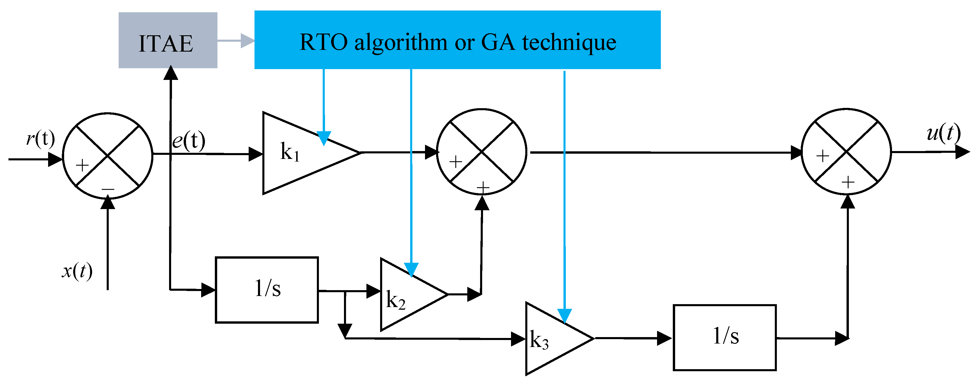
Figure 1. Proposed intelligent PII2 regulator.
Energies 18 05566 g001
Figure 2. Flowchart of a GA technique for calculating gain values for the PII2 controller.
Energies 18 05566 g002
Figure 3. Flowchart of the RTO algorithm for calculating gain values for the PII2 regulator.
Energies 18 05566 g003
Figure 4. Block diagram description of the proposed approach.
Energies 18 05566 g004
Figure 5. Block diagram of the designed DFIG energy control.
Energies 18 05566 g005
Figure 6. Suggested stator power control system.
Energies 18 05566 g006
Figure 7. First test results.
Energies 18 05566 g007aEnergies 18 05566 g007b
Figure 8. Second test results.
Energies 18 05566 g008aEnergies 18 05566 g008b
Figure 9. Third test results.
Energies 18 05566 g009aEnergies 18 05566 g009b
Table 1. Key Limitations that distinguish DPC of DFIG [13,16,17].
LimitationsIssueConsequence
Current and energy fluctuationsThe use of hysteresis controllers causes torque and current ripples.This can lead to increased mechanical stress on the wind turbine components and increased acoustic noise.
Switching frequency variationDPC often uses a switching table (similar to direct torque control), which can lead to variable switching frequency.This makes the design of filters more complex and may increase electromagnetic interference.
Sensitivity to parameter changesDPC performance is sensitive to machine parameter changes, especially rotor resistance and stator/rotor inductance.Variations (due to temperature, aging, etc.) can degrade control performance.
Difficulty in multivariable optimizationDPC typically targets instantaneous power control and may not optimize efficiency, thermal limits, or other secondary objectives.This can reduce overall system performance or energy yield.
Complexity in realizationThe real-time implementation of DPC requires fast processing and precise estimation of stator flux and power.This increases the computational burden and may require high-performance DSPs or FPGAs.
Lack of standardizationUnlike vector control, DPC techniques lack a universal or standardized structure.Implementation may vary widely, affecting reliability and reproducibility.
Limited low-speed operationAt low rotor speeds, the back-EMF is small, making it difficult to accurately estimate stator flux.This affects power control accuracy and dynamic performance.
Grid code complianceDPC may struggle to meet strict grid code requirements, such as Low Voltage Ride Through (LVRT) or reactive power support during faults.Additional control layers may be needed to satisfy grid codes.
Table 2. Highlights of proposed improvements in DPC.
ImprovementDescriptionPositiveNegatives
Model predictive control [18]Uses a predictive model to determine the optimal switching state that minimizes a cost function.
  • Can handle multiple constraints (e.g., thermal, power limits)
  • Predictive and adaptive
  • Excellent dynamic response
  • Very high computational cost
  • Complex tuning of cost function weights
  • Sensitive to model accuracy
DPC with adaptive control [19]Introduces adaptive laws to modify DPC parameters in real-time based on system behavior.
  • Self-tuning capability
  • Good performance under changing conditions
  • Slower response during adaptation phase
  • May have convergence/stability issues
Space vector modulation (SVM) [20].Replaces the switching table and hysteresis controllers with space vector modulation.
  • Better harmonics profile.
  • Fixed switching frequency.
  • Reduced current and energy fluctuations
  • Increased algorithm complexity.
  • Slower dynamic response compared to hysteresis comparator-based DPC.
  • Requires high-speed processors.
Sliding mode control (SMC) [21]Robust nonlinear control that enhances DPC under uncertainties and disturbances
  • Fast convergence
  • High robustness to parameter changes and disturbances.
  • Complicated implementation
  • Chattering problem (high-frequency switching noise)
Hybrid DPC (combining DPC with field-oriented control (FOC) or scalar control) [22]Merges DPC with other control strategies to balance performance and complexity.
  • Flexibility across operating conditions
  • Combines fast response (DPC) with smooth control (FOC)
  • Increased control structure complexity
  • Requires coordination between control schemes
  • More parameters to tune
Artificial Intelligence-based DPC (e.g., neural networks, fuzzy logic) [23,24]Integrates AI to enhance switching logic or estimate system parameters.
  • Improved fault tolerance
  • Adaptive to parameter changes
  • Better performance under nonlinear conditions
  • Less interpretable (“black box”)
  • Difficult to guarantee stability
  • Requires training or expert rule base
DPC with dynamic reference frame (DRF-DPC) [25]Utilizes rotating reference frames for control variables instead of stationary frames.
  • Simplified calculations
  • Better harmonic immunity
  • Improved power decoupling
  • Requires precise angle tracking
  • Increases complexity of coordinate transformations
DPC with observer-based flux estimation [26]Uses observers like Kalman Filters or Luenberger observers to improve flux estimation
  • Reduced sensor dependency
  • Better performance at low speed
  • Improved accuracy of control variables
  • Observer tuning is complex
  • Sensitivity to noise and model mismatches
Table 3. Comparison of the designed regulator with linear and nonlinear controls.
FeaturesControllers
PIDPISMCPII2MPCSynergetic Controller
Control typeLinearLinearNonlinearLinear (high order)Predictive model-based)Nonlinear
RobustnessModerateLow to moderateVery highModerate to highHighVery high
Order of integration11Discontinuous logic2 (double integration)Varies with prediction horizonCustom-defined via macrovars
ChatteringNoneNoneHighNoneNoneNone
Noise sensitivityLowHigh (due to derivative)LowLowModerateLow
Implementation easeModerateModerateModerateto hardModerateHard (requires full model)Moderate
Steady-state accuracyModerateHighHighVery highVery highVery high
Suitability for DPCBasicBetter than PIVery goodGoodExcellentExcellent
Table 4. Comparison of traditional DPC methods versus some existing DPC methods.
FeatureDPCNeural DPCSMC-DPCProposed Technique
Power & Torque RippleHighLowModerateLow
Dynamic ResponseFastFast Very fastFast
Robustness to Parameter VariationsLowHighVery highVery high
Switching FrequencyVariableVariable/FlexibleVariableFixed
Implementation ComplexityLowHighHighModerate
Grid Fault Performance (e.g., LVRT)PoorHighHighModerate to high
Flux Estimation AccuracyLow (needs sensors)ModerateModerateHigh
Computational BurdenLowHighHighModerate
Suitability for Real-time ControlExcellentGoodGoodGood
Sensor DependenceHighLow to moderateModerateLow
Table 5. Reduction rates obtained in test 1.
TechniquesCriteriaPs (W)Qs (VAR)
DPC-PIITAE17,720-
Ripples60,000106,742
Overshoot21,7408220
Response time (ms)1.270.069
SSE29,00041,128
PII2-GAITAE5617-
Ripples22,61021,863
Overshoot196,4401900
Response time (ms)3.584.50
SSE10007569.94
PII2-RTOITAE5636-
Ripples10,87023,546
Overshoot217,3703952.70
Response time (ms)3.564.50
SSE740012,683
Ratios (%)ITAEPII2-RTO/PI68.19-
PII2-GA/PI68.30-
PII2-RTO/PII2-GA−0.33-
RipplesPII2-RTO/PI81.8877.94
PII2-GA/PI62.3179.51
PII2-RTO/PII2-GA51.92−7.14
OvershootPII2-RTO/PI−89.9951.91
PII2-GA/PI−88.9376.88
PII2-RTO/PII2-GA−9.62−51.93
Response time (ms)PII2-RTO/PI−64.32−98.46
PII2-GA/PI−64.52−98.46
PII2-RTO/PII2-GA0.50
SSEPII2-RTO/PI74.4869.16
PII2-GA/PI96.5581.59
PII2/RTO/PII2-GA−86.48−40.31
Table 6. Numerical results and reduction ratios in the case of the second test.
TechniquesCriteriaPs (W)Qs (VAR)
DPC-PIITAE36,080-
Ripples165,000200,000
Overshoot36,63015,875
Response time (ms)0.660.070
SSE36,000100,000
PII2-GAITAE10,510-
Ripples34,44050,000
Overshoot95,9003804
Response time (ms)1.992.17
SSE400015,000
PII2-RTOITAE10,580-
Ripples45,00050,000
Overshoot127,2003804
Response time (ms)1.992.17
SSE12,90020,000
Ratios (%)ITAEPII2-RTO/PI70.67-
PII2-GA/PI70.87-
PII2-RTO/PII2-GA−0.6-
RipplesPII2-RTO/PI72.7275
PII2-GA/PI79.1275
PII2-RTO/PII2-GA−23.460
OvershootPII2-RTO/PI−71.2076.03
PII2-GA/PI−61.8076.03
PII2-RTO/PII2-GA−24.600
Response time (ms)PII2-RTO/PI−66.83−96.77
PII2-GA/PI−66.83−96.77
PII2-RTO/PII2-GA00
SSEPII2-RTO/PI64.1680
PII2-GA/PI88.8885
PII2/RTO/PII2-GA−68.99−25
Table 7. Reduction rates obtained in test 3.
Approaches CriteriaPs (W)Qs (VAR)
DPC-PIITAE17,670-
Ripples77,870100,000
Overshoot42008219
Response time (ms)0.950.068
SSE30,00012,700
PII2-GAITAE6567-
Ripples22,1007757.40
Overshoot110,40012,356
Response time (ms)2.553.04
SSE82007181.18
PII2-RTOITAE6563-
Ripples96006000
Overshoot129,86012,500
Response time (ms)2.553.04
SSE12,0006774.40
Ratios (%)ITAEPII2-RTO/PI62.85-
PII2-GA/PI62.83-
PII2-RTO/PII2-GA0.06-
RipplesPII2-RTO/PI87.6794
PII2-GA/PI71.6192.24
PII2-RTO/PII2-GA56.5622.65
OvershootPII2-RTO/PI−96.76−34.24
PII2-GA/PI−96.19−33.48
PII2-RTO/PII2-GA−14.98−1.15
Response time (ms)PII2-RTO/PI−62.74−97.76
PII2-GA/PI−62.74−97.76
PII2-RTO/PII2-GA00
SSEPII2-RTO/PI6046.65
PII2-GA/PI72.6643.45
PII2/RTO/PII2-GA−31.665.66
Table 8. Statistical study of THD and ITAE values of the proposed techniques.
TechniquesTHDITAEMaximum ValueMinimum ValueAverage ValueStandard Deviation
THDITAETHDITAETHDITAETHDITAE
PITest 16.40%17,72012.71%36,080 A5.70%17,670 A8.27%23,823.33 A3.15%8667.37 A
Test 212.71%36,080
Test 35.70%17,670
PII2-GATest 12.59%56173.98%10,510 A1.58%5617 A2.71%7254.33 A0.98%2141.11 A
Test 23.98%10,510
Test 31.58%6567
PII2-RTOTest 12.54%56363.94%10,580 A1.48%5636 A2.65%7593 A1.02%2145.76 A
Test 23.94%10,580 A
Test 31.48%6563 A
Table 9. Comparison of the results obtained with other control schemes in terms of the THD.
Algorithms THD (%)References
DPC-backstepping controller With harmonics suppression strategy4.59[57]
Without harmonics suppression strategy18.51
DPC4.88[58]
Virtual-Flux DPC4.19
DTC7.83[59]
2-level DTC8.75[60]
Integral SMC9.71[61]
DTC6.70[62]
DTC-PI12[63]
Ant-colony optimization-based DTC7.19
PII2-GA2.59Proposed regulators
PII2-RTO2.54
Disclaimer/Publisher’s Note: The statements, opinions and data contained in all publications are solely those of the individual author(s) and contributor(s) and not of MDPI and/or the editor(s). MDPI and/or the editor(s) disclaim responsibility for any injury to people or property resulting from any ideas, methods, instructions or products referred to in the content.