Abstract
The rapid advancement of more electric aircraft technology has led to the widespread integration of non-linear loads into aircraft power supply systems. Passivity-based control (PBC) is a well-established method for enhancing system stability. However, existing research mainly focuses on current-controlled converters with control strategies confined to the fundamental component, while studies on passivity control for voltage-controlled converters incorporating harmonic mitigation remain limited. To enhance the stability of the standalone converters in aircraft power systems, this paper first proposes a method that transforms the converter output impedance into a product of two sub-impedances, thereby revealing the compensation mechanism of the output current feedforward active damping on the converter output impedance. Based on this insight, a second-order generalized integrator based active damping strategy is introduced to achieve sub-impedance phase compensation. Furthermore, to mitigate the adverse effect on converter passivity introduced by resonant controllers, a phase lead angle design strategy is proposed to ensure converter passivity from 0 Hz to the Nyquist frequency without compromising harmonic mitigation capability. Experimental results on a 5 kW three-phase converter validate the effectiveness of the proposed method.
1. Introduction
More Electric Aircraft (MEA) represents a revolutionary transformation in aircraft energy systems [1]. It replaces conventional hydraulic and pneumatic systems with electrical systems to optimize the aircraft secondary energy system, thereby enhancing reliability, safety, and maintainability. Currently, electrical power has become one of the most critical energy sources in MEA. The 270 V high-voltage DC (HVDC) and 115/200 V, 360–800 Hz variable-frequency AC power supply systems are increasingly superseding conventional 28 V low-voltage DC and 115 V/400 Hz constant-frequency AC systems [2,3]. Meanwhile, due to the diversity of load types, aircraft power supply systems typically incorporate multiple types of power sources. As a result, the medium frequency 115 V/400 Hz inverter, which serves as the interface power converter between DC and AC sub-grids, has attracted significant research interest and widespread application [4].
High-performance aviation inverters are required to provide reliable, high-quality power to the critical loads during the taxi, take-off, cruise and landing phases of the aircraft. Various types of power electronic converters, and motors included in the aircraft have negative input impedance and nonlinear characteristics, which may lead to high harmonic voltage/current and high-frequency oscillations at the AC side of the converter. These phenomena can seriously affect the system power quality and reliability, reduce the system efficiency, and even degrade the performance of the converter and the critical loads. In addition, the computation, sampling and pulse width modulation (PWM) delay introduced by the digital controller [5] will not only decrease the bandwidth of the inverter control system, but also introduce negative resistance to the inverter output impedance between one-sixth and one-half of the switching frequency. As a result, resonance may occur between the inverter and the load, and may lead to system instability.
Extensive research has been conducted on the internal stability of LCL-filtered grid-connected converters. Among the solutions, passive damping, which inserts a damping resistor in series with the filter capacitor, offers simplicity and high reliability. However, this method induces additional power losses and degrades the harmonic attenuation performance of the filter [6,7]. To avoid the power losses caused by the damping resistor, active damping is proposed by feeding back measurable electrical variables into the control loop to adjust the system damping factor, e.g., filter capacitor current [8,9], filter capacitor voltage [10], grid side current [11], or converter side current [12].
Although active damping methods achieve higher efficiency than passive damping techniques, they are adversely affected by computational and PWM delays inherent in digitally controlled systems [13], which can cause system instability if filter resonance frequency lies within 0 Hz and one-sixth of the sampling frequency (fs/6) for grid side current-controlled converters [14]. Note that the instability range for converter side control is (fs/6, fs/2). To widen the system stability region, numerous delay compensation strategies have been introduced [15,16,17], these approaches mainly focus on enhancing the stability margin of a single converter. Consequently, their applicability is generally confined to the converter internal stability analysis and cannot guarantee the system stability in the case of the capacitive load or constant power load [14].
Impedance based stability analysis methods have been applied to achieve external stability in distributed generation systems in which parallel power electronic converters are interactively connected with the grid [18,19,20], as shown in Figure 1. Sun proposes that in a grid-interactive system if the phase difference between the grid impedance and the inverter output impedance is greater than 180° at the frequency where the impedance amplitude equals each other, resonance will occur [21]. However, a limitation of these methods is their inability to guarantee stability across a wide range of load impedances, as a change in the load can lead to resonance. To address this limitation, external stability can be ensured by a design based on passivity theory [22]. Essentially, passivity reflects the ability to dissipate energy. According to the theory, if the output admittance of the inverter has a non-negative real part, it acts passively. When critical resonances fall within this passive frequency range, the inverter prevents destabilization, thereby ensuring system stability [22,23].
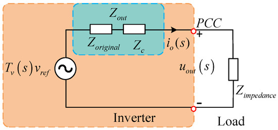
Figure 1.
Impedance model of the inverter.
By analyzing the effect of LCL filter resonance frequency on the range of output impedance passive region for a current-controlled inverter [24], a design guideline of the filter parameters optimization strategy is proposed to expand the inverter passive region. However, non-passive region still exists below Nyquist frequency. Meanwhile, active damping methods can also be utilized to widen the impedance passive region of the inverter, and various active damping strategies have been extensively studied by researchers. In [25], passivity characteristic of a converter-side current-controlled inverter with an LCL filter is investigated. It is found that the inverter output admittance can have a negative real part in certain frequency regions, which can lead to instability. And a damping control strategy using capacitor voltage feedforward was developed to extend the passive region up to the Nyquist frequency under the cost of an additional analog high-pass filter. In [26], a first-order phase-lead/phase-lag based capacitor current damping strategy is proposed to enhance both internal and external stability. In [27], a second order high pass filter is utilized as the feedforward transfer function, and maintain the system passivity above 18th order harmonic. In [28], a proportional-integral controller is integrated into the capacitive voltage feedforward loop to ensure a positive equivalent resistance approach the Nyquist frequency. Moreover, a delay compensator can be added in the control loop to compensate the phase lag caused by the digital control. A differential loop is embedded into the current control loop to mitigates the negative effect caused by the delay via zero-pole cancellation [29]. However, the aforementioned strategies primarily focus on current-controlled converters for fundamental current regulation, and thus cannot be directly applied to voltage-controlled converters as they fail to address the critical influence of the outer voltage loop on converter passivity, leaving the challenge of achieving passivity with harmonic mitigation largely unresolved.
Only a few studies address impedance stability and passivity enhancement for voltage-controlled inverters. Prior work, such as [30,31] establish passivity through virtual impedance and lead-lag compensation. However, these methods are primarily implemented in grid-connected converters and do not solve the challenge of maintaining passivity while providing high-order harmonic compensation. It is worth noting that Multi-Sample-PWM method can effectively reduce the digital delay and thus widen the system passive region without additional sensors and power losses [32], but can introduce unwanted nonlinearities to the system and worsen the system power quality [33].
Among the above-mentioned research and analysis of the inverter impedance passivation strategies, the frequency domain expression of the inverter output impedance is complicated, especially after inserting the state variable feed-forward control loop. This can increase the system design difficulty dramatically. Therefore, this paper proposes to reshape the inverter output impedance and simplify the system controller design process. Section 2 initially elaborates the converter impedance characteristic with conventional current feedback method. Section 3 investigates the proposed passivity enhancement strategy, while Section 4 illustrates the passivity-based voltage harmonic controller method and parameter design strategy. Experimental results are analyzed and discussed in Section 5. Finally, conclusions are presented in Section 6.
2. Proportional Current Feedback Based Passivity Enhancement Method
Conventional passivity-based control strategies normally utilize filter state variable feedforward with different delay and frequency domain correction algorithms to reshape the inverter output impedance.
2.1. Impedance Model of the Inverter
The main circuit topology of the three-phase inverter is shown in Figure 2, where Vin is the dc bus voltage, Cin is the dc-side capacitor, S1–S6 are SiC MOSFETs-based three-phase bridge circuits, and L is the filter inductor, C is the filter capacitor. , , and iLk, uCk, iok and uk are the inductor current, capacitor voltage, load current, and bridge midpoint voltage, respectively. It is worth noting that all inherent parasitic resistances were neglected in the model to represent a worst-case scenario from a damping perspective, as they would otherwise provide inherent passive damping in practice.
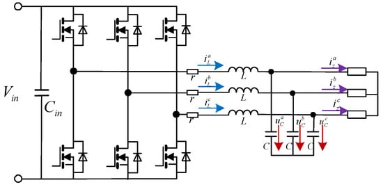
Figure 2.
Power circuit of a LC-filtered inverter.
Based on Kirchhoff’s law, state equation of the inverter is given as:
Block diagram of the passivity-based inverter control strategy including voltage feedforward and current feedforward is given in Figure 3a, where Zv is the output current feedforward damping coefficient, Hv(s) is the output voltage feedforward damping coefficient, Gv(s) is the voltage loop proportional resonance (PR) controller, Gi(s) is the current loop controller, and Gd(s) is the computational and PWM delay. Note that s is the Laplace operator.
where Ts is the control period, ω1 is the fundamental frequency, kpi is the current loop gain, kpv and kiv are the voltage loop proportional and integral gain of the controller, respectively.
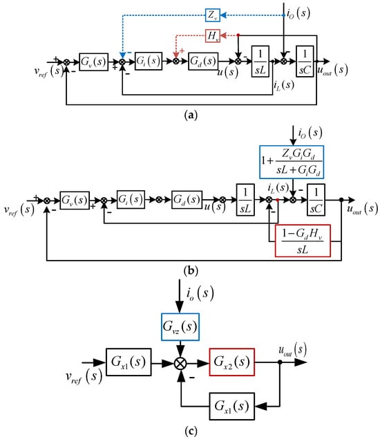
Figure 3.
Equivalent model of the dual-loop control strategy. (a) original block diagram, (b) simplified representation, (c) block diagram for impedance modeling.
The ideal resonant controller is employed for its enhanced frequency adaptation capability compared to the non-ideal counterpart [34]. Note the inner loops are implemented in two-phase stationary frame, and are designed before further modifying the converter output impedance. Then, current loop controller parameter kpi is set to achieve the desired control bandwidth. Note that this bandwidth should be smaller than 0.3 times of the filter resonant frequency to avoid instability issues. Meanwhile, the outer voltage loop is designed by setting the phase margin and gain margin of the converter to 45° and 3 dB, respectively. Detailed parameters design process is not shown here, since it is well documented in previous publications. Detailed parameter design process follows established methodologies [34] and is therefore not repeated here for brevity.
To evaluate the passive range of the inverter output impedance, a simplified system structure is obtained by moving backward the summing points of both the current and voltage feedforward loops, as depicted in Figure 3b. This was followed by sequentially closing the control loops, proceeding from the inner current loop to the outer voltage loop, which yields the model in Figure 3c. Finally, the output impedance of the inverter can be derived as:
where
To clearly show the passivity-based impedance design method, system parameters are listed in Table 1, and the parameter values can ensure the system stability with satisfied dynamic response. The Bode plot in Figure 4 demonstrates that the converter output impedance becomes non-passive at frequencies approaching the Nyquist frequency.

Table 1.
System Parameters.
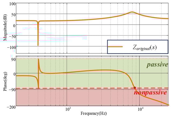
Figure 4.
Output impedance of the converter.
2.2. Passive Region of the Inverter
According to (5), the real part of the output impedance Re{Zout(jω)} can be given as
where
Letting Re{Zout(jω)} = 0 yields that the output impedance has the widest range of passivity region when the current proportional feedforward Zv satisfies (11).
If Zv does not satisfy (10), the real part of the output impedance Re{Zout(jω)} has a negative value in the frequency band (fs/10~fs/6), which implies a non-passive system. The three-dimensional plot of the current feedforward coefficient Zv versus the real part of the output impedance Re{Zout(jω)} is shown in Figure 5. The x-axis is the normalized frequency f/fs, y-axis is the proportional current feedforward coefficient Zv, and the z-axis is the real part of the output impedance Re{Zout(jω)}. The red plane implies that the real part of the output impedance is zero. From the figure, it can be seen that as Zv increases, the frequency range in which Re{Zout(jω)} is greater than zero gradually expands, i.e., the system passive region gradually increases. However, when the frequency approaches the Nyquist frequency fNyquist (0.475fs~0.5fs), Re{Zout(jω)} gradually decreases and falls below zero plane due to the influence of the system delay, and the system becomes non-passive. Therefore, the current feedforward parameters need to be further tuned to enhance the system passivity.
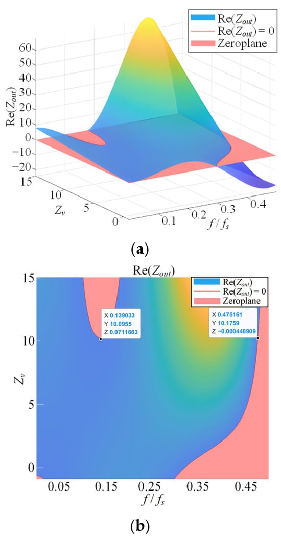
Figure 5.
Relationship between Zv and Re{Zout(jω)}. (a) 3D View, (b) 2D Projection.
Furthermore, it can be seen from (10) that if the LC filter parameters fluctuate due to aging or manufacturing process, the value of Zv also varies, which affects the system passivity.
3. SOGI Based Current Feedforward Control Strategy for Passivity Enhancement
In order to realize phase compensation of the output impedance, Zout(s) is transformed into the product of Zoriginal(s) and Gvz(s). So the effect of the current feedforward coefficient on the system passivity can be evaluated as:
According to the analysis in Section 2, when Zv = 0, the system output impedance Zoriginal(jω) will drop into the non-passive region after the critical frequency fcritical due to the impact of delay. Therefore, in this frequency band, the phase ∠Gvz(jω) of Gvz(s) is used to compensate the phase drop of the inverter’s output impedance phase ∠Zoriginal(jω) caused by the system delay, so as to enhance the passivity of the system output impedance, and ensure that the phase relationship of the system meets (14) to guarantee the passivity of the system.
To achieve this goal, this paper proposes to utilize second-order generalized integrator (SOGI) to achieve system phase compensation. Figure 6 shows the block diagram of the SOGI, where the output signals v′(s) and qv′(s) are the in-phase and quadrature-phase signals of the input signal v(s), respectively [35,36], ω′ and k are the center frequency and gain factor of the filter, respectively. The characteristic transfer functions of the SOGI block, Gv′(s) and Gqv′(s), which relate the input to the in-phase and quadrature-phase outputs respectively, are obtained as:
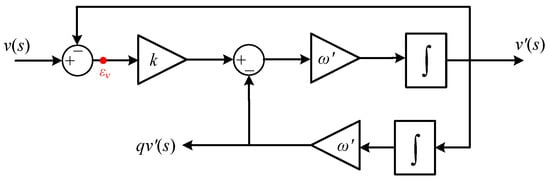
Figure 6.
Block diagram of SOGI.
In this paper, the reciprocal of the error transfer function E(s) is used to provide the phase lead required for the passivity design, which can be expressed as:
The Bode plot of Er(s) is shown in Figure 7. It can be seen that the phase lead characteristic between 0 and ω’ meets the requirement for phase compensation at high frequencies. However, the magnitude at ω’ is infinite, which may amplify high-frequency noise in the system. Therefore, damping is introduced into Er(s) and transformed it into a quasi-resonant form, as shown in (18).
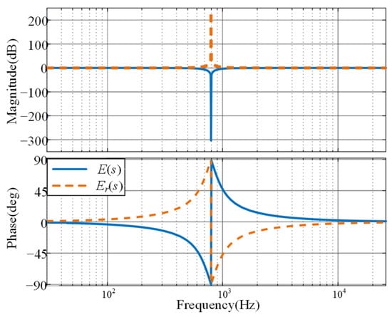
Figure 7.
Bode plots of E(s) and Er(s).
In order to simplify the output impedance of the system after compensation, and eliminate the influence of the current loop Gi(s), time delay Gd(s) and filter inductance L on the impedance change term, the transfer function of the current feedforward active damping Zv*(s) is designed as
where Ga(s) is the transfer function of lead-lag compensator.
In order to make sure that ErQ(s) can provide phase lead compensation up to Nyquist frequency fNyquist, the value of ω’ is set to 2π × fNyquist rad/s, the value of ωc is 2000 rad/s. After transformation, ErQ(s) provides a phase increase from 0° to 90° between the critical frequency fcritical and the Nyquist frequency.
Substituting (19) into (12), expression of the compensated converter output impedance can be obtained as (21), and the Bode plot of the impedance is depicted in Figure 8. The plot indicates that the phase angle of the output impedance is within the passive region between fcritical and fs/2, and the system output impedance is passive across the entire frequency range. And the current feedforward controller is only influenced by the inductance L, and variations in the inductance have minimal impact on the passivity of the output impedance Zout(z). Even both the LC filter parameters deviate 10% from the nominal value, the inverter output impedance can still maintain passivity across the entire frequency range.
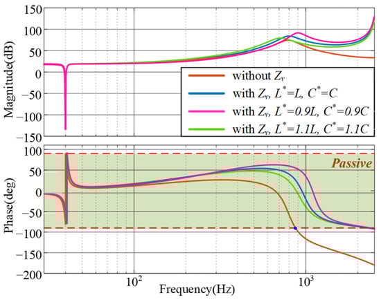
Figure 8.
Modified output impedance of the converter.
4. Passivity-Based Resonant Controller Design Strategy
Generally, multiple parallel resonant controllers are employed in the voltage controller to provide high gains as well as compensate system delays at desired harmonic frequencies. Then, the voltage controller can be expressed as
where kres is the resonant controller gain, n is the highest harmonic order that can be compensated, h is the harmonic order that needs to be compensated, and φc is the induced phase leading angle at the resonant frequency. Conventionally, the value of nω1 is required to be sufficiently lower than ωres to avoid instability issues caused by the system phase lag.
Conventionally, φc is tuned equal with the inverse of the system phase angle [37] to achieve high compensation accuracy and stability margin, as shown in (23).
Although the designed phase angle ensures a sufficient stability margin, it causes the inverter output impedance phase angle at harmonic frequencies (hω1) to exceed the passive region, resulting in negative resistance, as shown by the blue curve in Figure 9. While the inverter output impedance, Zout(s), satisfies passivity requirements in the low- and high-frequency bands, the output impedance phase angle at harmonic frequencies is adversely influenced by the resonant controller, causing it to exceed the passive region.
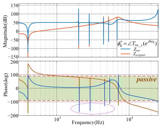
Figure 9.
Output impedance with conventional phase leading angle design method.
As can be seen from Figure 9, the phase angle of the output impedance at harmonic frequencies rapidly drops −90°, and falls from the passive region to the non-passive region, then sharply rising back into the passive region. This behavior indicates that the real part of the impedance has a zero-crossing near each harmonic frequency. If the real part of the output impedance, Re{Zout(jω)}, reaches its local minimum at this zero-crossing, then Re{Zout(jhω)} ≥ 0, and the output impedance can be made passive near the hω1. To achieve this, phase leading angle of the resonant controller should comply with the following restrictions:
The phase leading angles for the 5th, 7th, 11th, 13th, 17th, 19th, and 23rd harmonics are calculated and listed in Table 2.
Table 2.
Phase Leading Angle.
Figure 10 presents the Bode plot of the output impedance with the optimized phase leading angle. As shown, the phase angle of the inverter output impedance at high-order harmonics remains within the passive region, confirming that the system achieves a passive output impedance across the entire frequency range. This wideband passivity is the result of collaborative action between the feedforward controller and the resonant controllers: phase leading angle of the resonant controller ensures passivity locally around its center frequency, while the SOGI based current feedforward controller guarantees it across the remainder of the spectrum.
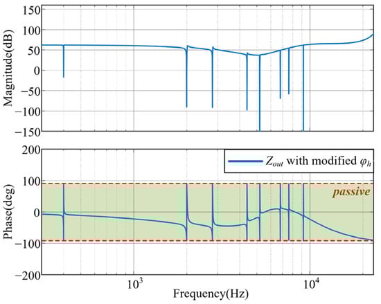
Figure 10.
Output impedance with optimized phase leading angle.
It is worth noting that the SOGI and resonant controllers are discretized using the first-order hold method and the impulse invariant method, respectively, to ensure accurate resonance peak and phase characteristics even at high frequencies [38].
5. Simulation Results
The performance of the proposed passivity enhancement strategy was evaluated through simulation, using a PLECS model that represented the physical switched converter system in both discrete and continuous time. This modeling approach is capable of accurately incorporating the delays inherent in a real digital regulator system. The system parameters are shown in Table 1, Table 2 and Table 3. Note that the filter parameters are the same as those in the above analysis.
Table 3.
Main Parameters of the Inverter.
Figure 11 presents the dynamic response of the inverter output voltage and current under a sudden load step-up at the rated 5 kW condition. As observed, the output voltage recovers to its steady-state value within two cycles.
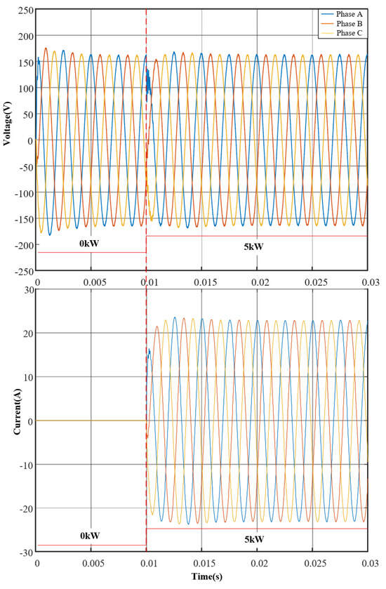
Figure 11.
Output voltage during load change.
A comparison of the output voltage waveforms without and with the resonant controller is provided in Figure 12a and Figure 12b, respectively. After activating the resonant controller, the voltage waveform exhibits a more sinusoidal shape, and the corresponding total harmonic distortion (THD) is reduced from 18.83% to 4.02%.
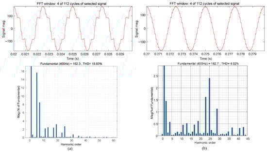
Figure 12.
Output voltage and its spectrum with non-linear load. (a) Without resonant controllers, and (b) with resonant controllers.
Furthermore, as demonstrated in Figure 13, enabling the enhanced current feedforward controller effectively suppresses high-frequency oscillations and restores converter stability. Note that a 5 kW L-filtered three-phase PFC converter serves as the load in this case.
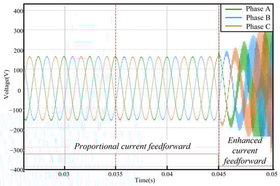
Figure 13.
Output voltage with/without the proposed passivity enhancement strategy.
6. Experimental Results
To validate the effectiveness of the proposed control strategy, experimental results are obtained using the testbed shown in Figure 14, and the system parameters are the same as those in the simulation. The controller was implemented using a TMS320F28335 DSP (Texas Instruments, Dallas, TX, USA) firstly driving an R load, and then a non-linear load. Voltage signals were measured using a MSO46 oscilloscope (Tektronix, Beaverton, OR, USA, 350 MHz bandwidth, 6.25 GS/s sampling rate) equipped with a P5200A differential voltage probe (Tektronix, USA, 50 MHz bandwidth). The measurement system featured automatic calibration and was set to Autozero for DC bias. For signal processing, a second-order Butterworth anti-aliasing filter with a 30 kHz cutoff frequency was employed. THD analysis was performed using a Hann window to minimize spectral leakage, with a sampling duration of 25 ms (covering 10 cycles of the 400 Hz output) and 156,250 FFT points. To ensure statistical reliability, all measurements were repeated three times, with five consecutive cycles analyzed per repetition.
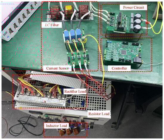
Figure 14.
Experimental platform.
Figure 15 shows the dynamic waveforms of the inverter output voltage and current when the system is subjected to sudden load step-up at a rated load of 5 kW. It can be seen that the inverter output voltage can return to its steady-state within 2 cycles.
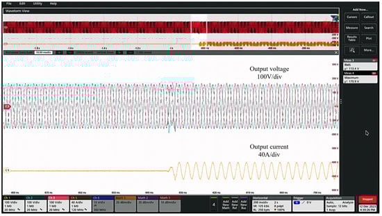
Figure 15.
Output voltage during load change.
Figure 16 depicts the output voltage waveform with a 5 kW, L-filtered, three-phase PFC converter serving as the load. The results demonstrate that the proposed enhanced passivity control strategy maintains stability under different filter inductances (0.2 mH and 0.4 mH). In contrast, the conventional current feedforward strategy exhibits high-frequency oscillations at L = 0.2 mH. The system recovers stable operation once the proposed strategy is reactivated, confirming its superior robustness.
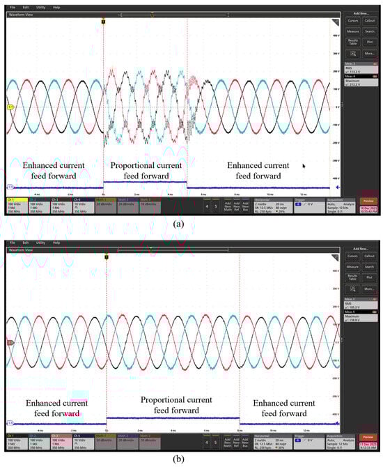
Figure 16.
Output voltage with/without the proposed passivity enhancement strategy. (a) L = 0.2 mH, and (b) L = 0.4 mH.
Figure 17a shows the output voltage waveform without harmonic compensation under a 5 kW diode rectifier. In this case, the output AC voltage contains a large number of high-order harmonics, such as the 5th, 7th, 11th, and 13th. As shown by the FFT analysis of this output voltage in Figure 17b, the THD is 16.05% ± 0.3%, and the 19th harmonic alone reaches 8.3%, leading to severe waveform distortion.
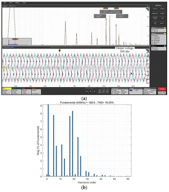
Figure 17.
Output voltage and its spectrum without resonant controller. (a) voltage, (b) spectrum.
The output voltage waveforms with up to 23rd order harmonic compensated is shown in Figure 18. As can be seen, the voltage quality is significantly improved, and the corresponding specific high-order harmonics are effectively suppressed. The performance comparison under different control schemes is summarized in Table 4.
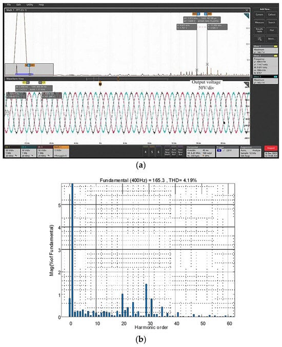
Figure 18.
Output voltage and its spectrum with resonant controller. (a) voltage, (b) spectrum.
Table 4.
Output voltage THD with different control methods.
As shown in the table, with the implemented resonant controller, the THD decreases to 4.19% ± 0.3%, which meets the requirements of MIL-STD-704F [39]. However, high-order harmonics such as the 25th, 29th, and 31st still exist. This is due to the 50 kHz sampling frequency, which provides an insufficient number of samples per cycle for the controller to effectively track and suppress these specific harmonics.
7. Conclusions
This paper has developed a comprehensive control strategy to achieve passivity in an LC-filtered aviation mid-frequency inverter across the full frequency range from 0 Hz to the Nyquist frequency, while maintaining harmonic compensation capability. By reformulating the inverter impedance model as a product of two polynomials, the current feedforward path gain is simplified. Based on this transformed model, a SOGI based passivity enhancement strategy is proposed, which ensures passive output impedance up to the Nyquist frequency. Additionally, a phase leading angle design method is introduced that identifies local extrema of the output impedance to guarantee system passivity without compromising passivity at selected harmonic frequencies. The proposed approach is validated through both simulation and experimental tests under various load conditions. Results demonstrate that the converter achieves steady state within two cycles and maintains voltage THD below 5% even under nonlinear loads.
Author Contributions
Conceptualization, X.Z.; Data curation, A.W.; Formal analysis, A.W.; Funding acquisition, X.Z.; Methodology, A.W.; Project administration, X.W.; Supervision, X.Z. and X.W.; Visualization, X.L.; Resources, X.C.; Software, X.C.; Validation, X.C.; Investigation, X.W.; Writing—original draft, A.W.; Writing—review & editing, Y.J., X.L. and X.Z. All authors have read and agreed to the published version of the manuscript.
Funding
This research was supported by the National Natural Science Foundation of China, grant number 52107208.
Data Availability Statement
Data are contained within the article.
Conflicts of Interest
The authors declare no conflicts of interest.
References
- Barzkar, A.; Ghassemi, M. Components of Electrical Power Systems in More and All-Electric Aircraft: A Review. IEEE Trans. Transp. Electr. 2022, 8, 4037–4053. [Google Scholar] [CrossRef]
- Buticchi, G.; Wheeler, P.; Boroyevich, D. The More-Electric Aircraft and Beyond. Proc. IEEE 2023, 111, 356–370. [Google Scholar]
- Catalbas, N.; Pakfiliz, A.G.; Soysal, G. Multilevel Aircraft-Inverter Design Based on Wavelet PWM for More Electric Aircraft. Energies 2024, 17, 2054. [Google Scholar] [CrossRef]
- Emadi, K.; Ehsani, M. Aircraft power systems: Technology, state of the art, and future trends. IEEE Aerosp. Electron. Syst. Mag. 2000, 15, 28–32. [Google Scholar] [CrossRef]
- Sakharuk, T.; Lehman, B.; Stankovic, A. Effects of finite switching frequency and delay on PWM controlled systems. IEEE Trans. Circuits Syst. I Fundam. Theory Appl. 2000, 47, 555–567. [Google Scholar] [CrossRef]
- Liserre, M.; Blaabjerg, F.; Hansen, S. Design and control of an LCL filter-based three-phase active rectifier. IEEE Trans. Ind. Appl. 2005, 41, 1281–1291. [Google Scholar] [CrossRef]
- Wu, W.; He, Y.; Tang, Y.; Blaabjerg, F. A new design method for the passive damped LCL and LLCL filter-based single-phase grid-tied inverter. IEEE Trans. Ind. Electron. 2013, 60, 4339–4350. [Google Scholar] [CrossRef]
- Tang, Y.; Loh, P.; Wang, P.; Choo, F.; Gao, F.; Blaabjerg, F. Generalized design of high performance shunt active power filter with output LCL filter. IEEE Trans. Ind. Electron. 2012, 59, 1443–1452. [Google Scholar]
- Zhang, H.; Wang, X.; He, Y.; Pan, D.; Ruan, X. A Compensation Method to Eliminate the Impact of Time Delay on Capacitor-Current Active Damping. IEEE Trans. Ind. Electron. 2022, 69, 7512–7516. [Google Scholar] [CrossRef]
- Chen, W.; Zhang, Y.; Tu, Y.; Guan, Y.; Shen, K.; Liu, J. Unified Active Damping Strategy Based on Generalized Virtual Impedance in LCL-Type Grid-Connected Inverter. IEEE Trans. Ind. Electron. 2023, 70, 8129–8139. [Google Scholar] [CrossRef]
- Matijevic, E.; Sharma, R.; Zare, F.; Kumar, D. Extremum Seeking as a Tool for Active Damping of Active Front-End Converters. IEEE Trans. Ind. Electron. 2023, 70, 3404–3413. [Google Scholar] [CrossRef]
- Chen, W.; Zhang, Y.; Tu, Y.; Shen, K.; Liu, J. Active Damping Control for LCL Filters with Inverter-Side Current Feedback Only. IEEE Trans. Power Electron. 2022, 37, 10065–10069. [Google Scholar] [CrossRef]
- Parker, S.; McGrath, B.; Holmes, D. Regions of active damping control for LCL filters. IEEE Trans. Ind. Appl. 2014, 50, 424–432. [Google Scholar] [CrossRef]
- Akhavan, A.; Mohammadi, H.; Vasquez, J.; Guerrero, J. Passivity-based design of plug-and-play current-controlled grid-connected inverters. IEEE Trans. Power Electron. 2020, 35, 2135–2150. [Google Scholar] [CrossRef]
- Li, C.; Xie, C.; Ma, G.; Peng, C.; Zou, J. Passivity and Injection Current Quality Enhancement for Single Inverter-Side Current Feedback LCL-Type Grid-Following Inverters. IEEE J. Emerg. Sel. Top. Power Electron. 2025, 13, 2500–2511. [Google Scholar] [CrossRef]
- Huang, Y.; Xie, C.; Peng, C.; Zhou, D.; Zou, J. Rethink and Design of Capacitor-Current-Feedback Active Damping for Grid-Following Inverters from a Passivity Enhancement Perspective. IEEE J. Emerg. Sel. Top. Power Electron. 2024, 12, 2947–2959. [Google Scholar] [CrossRef]
- Ye, J.; Wang, H.; Li, B.; Huang, Y.; Xu, J.; Shen, A. Passivity-Based Controller Design of PCC Voltage Feedforward Active Damping for Grid-Connected Inverters. IEEE Trans. Ind. Electron. 2024, 71, 8752–8762. [Google Scholar] [CrossRef]
- Zhang, Y.; Li, K.; Zhang, L. Hybrid ANPC Grid-Tied Inverter Design with Passivity-Based Sliding Mode Control Strategy. Energies 2024, 17, 3655. [Google Scholar] [CrossRef]
- Xia, Y.; Li, H.; Ye, S.; Shi, J.; Yang, Y.; Li, K. Enhanced MMC-HVDC Power Control via Adaptive VSG-PBC in Weak Grid Environments. Energies 2025, 18, 3327. [Google Scholar] [CrossRef]
- Wen, B.; Burgos, R.; Boroyevich, D.; Mattavelli, P.; Shen, Z. AC stability analysis and DQ frame impedance specifications in power-electronics based distributed power systems. IEEE J. Emerg. Sel. Top. Power Electron. 2017, 5, 1455–1465. [Google Scholar] [CrossRef]
- Sun, J. Impedance-based stability criterion for grid-connected inverters. IEEE Trans. Power Electron. 2011, 26, 3075–3078. [Google Scholar] [CrossRef]
- Harnefors, L.; Wang, X.; Yepes, A.; Blaabjerg, F. Passivity-based stability assessment of grid-connected VSCs: An overview. IEEE J. Emerg. Sel. Top. Power Electron. 2016, 4, 116–125. [Google Scholar] [CrossRef]
- Brune, O. Synthesis of a Finite Two-Terminal Network Whose Driving-Point Impedance Is a Prescribed Function of Frequency. Ph.D. Thesis, Massachusetts Institute of Technology, Cambridge, MA, USA, 1931. [Google Scholar]
- Xie, C.; Li, K.; Zou, J. Passivity-Based Design of Grid-Side Current-Controlled LCL-Type Grid-Connected Inverters. IEEE Trans. Power Electron. 2020, 35, 9813–9823. [Google Scholar] [CrossRef]
- Harnefors, L.; Yepes, A.; Vidal, A.; Doval-Gandoy, J. Passivity-based controller design of grid-connected VSCs for prevention of electrical resonance instability. IEEE Trans. Ind. Electron. 2015, 62, 702–710. [Google Scholar] [CrossRef]
- Li, S.; Lin, H. Passivity Enhancement-Based General Design of Capacitor Current Active Damping for LCL-Type Grid-Tied Inverter. IEEE Trans. Power Electron. 2023, 38, 8223–8236. [Google Scholar] [CrossRef]
- Chen, H.; Cheng, P.; Wang, X. A Passivity-Based Stability Analysis of the Active Damping Technique in the Offshore Wind Farm Applications. IEEE Trans. Ind. Appl. 2018, 54, 5074–5082. [Google Scholar] [CrossRef]
- He, Y.; Wang, X.; Ruan, X. Capacitor-Current Proportional-Integral Positive Feedback Active Damping for LCL-Type Grid-Connected Inverter to Achieve High Robustness Against Grid Impedance Variation. IEEE Trans. Power Electron. 2019, 34, 12423–12436. [Google Scholar] [CrossRef]
- Wang, X.; Blaabjerg, F.; Loh, P. Passivity-Based Stability Analysis and Damping Injection for Multi-paralleled VSCs with LCL Filters. IEEE Trans. Power Electron. 2017, 32, 8922–8935. [Google Scholar] [CrossRef]
- Liao, Y.; Wang, X.; Blaabjerg, F. Passivity-Based Analysis and Design of Linear Voltage Controllers For Voltage-Source Converters. IEEE Open J. Ind. Electron. Soc. 2020, 1, 114–126. [Google Scholar] [CrossRef]
- Wu, G.; He, Y.; Zhang, H. Passivity-Based Stability Analysis and Generic Controller Design for Grid-Forming Inverter. IEEE Trans. Power Electron. 2023, 38, 5832–5843. [Google Scholar] [CrossRef]
- Petric, I.; Mattavelli, P.; Buso, S. Multi-Sampled Grid-Connected VSCs: A Path Toward Inherent Admittance Passivity. IEEE Trans. Power Electron. 2022, 37, 7675–7687. [Google Scholar] [CrossRef]
- Petric, I.; Mattavelli, P.; Buso, S. Investigation of Nonlinearities Introduced by Multi-sampled Pulse-width Modulators. IEEE Trans. Power Electron. 2022, 37, 2538–2550. [Google Scholar] [CrossRef]
- Zmood, D.; Holmes, D. Stationary frame current regulation of PWM inverters with zero steady-state error. IEEE Trans. Power Electron. 2003, 18, 814–822. [Google Scholar] [CrossRef]
- Rodriguez, P.; Luna, A.; Candela, I. Grid synchronization of power converters using multiple second order generalized integrators. In Proceedings of the 2008 34th Annual Conference of IEEE Industrial Electronics, Orlando, FL, USA, 10–13 November 2008; pp. 755–760. [Google Scholar]
- Li, M.; Matas, J.; Mariachet, J.E.; Branco, C.G.C.; Guerrero, J.M. A Fast Power Calculation Algorithm for Three-Phase Droop-Controlled-Inverters Using Combined SOGI Filters and Considering Nonlinear Loads. Energies 2022, 15, 7360. [Google Scholar] [CrossRef]
- Yepes, A.; Freijedo, F.; Lopez, O.; Doval-Gandoy, J. Analysis and Design of Resonant Current Controllers for Voltage-Source Converters by Means of Nyquist Diagrams and Sensitivity Function. IEEE Trans. Ind. Electron. 2011, 58, 5231–5250. [Google Scholar] [CrossRef]
- Yepes, A.; Freijedo, F.; Doval-Gandoy, J.; López, Ó.; Malvar, J.; Fernandez-Comesaña, P. Effects of Discretization Methods on the Performance of Resonant Controllers. IEEE Trans. Power Electron. 2010, 25, 1692–1712. [Google Scholar] [CrossRef]
- MIL-STD-704F; Aircraft Electric Power Characteristics. Department of Defense: Arlington, VA, USA, 2004.
Disclaimer/Publisher’s Note: The statements, opinions and data contained in all publications are solely those of the individual author(s) and contributor(s) and not of MDPI and/or the editor(s). MDPI and/or the editor(s) disclaim responsibility for any injury to people or property resulting from any ideas, methods, instructions or products referred to in the content. |
© 2025 by the authors. Licensee MDPI, Basel, Switzerland. This article is an open access article distributed under the terms and conditions of the Creative Commons Attribution (CC BY) license (https://creativecommons.org/licenses/by/4.0/).