1. Introduction
The increasing global energy demand is driving energy transition, resulting in a larger portion of renewable energy in overall energy generation. Consequently, the number of microgrids and energy storage systems is expanding, and grid-connected inverters (GCIs) play an increasingly significant role in delivering power to the grid [
1].
The growing number of GCIs integrated in the utility grid poses significant challenges for the current control design of inverter systems. The efficiency of distributed generation (DG) systems depends on the GCIs that maintain stable output currents even under abnormal grid conditions. In recent years, a GCI has become an essential component for injecting renewable energy into the grid. As a result, the mitigating strategy of significant disturbances caused by the grid has become increasingly important for maintaining power quality [
2]. Particularly, GCIs should have low output current distortion [
3] and meet the power quality standards, such as IEEE Std.-1547 [
4].
Typically, pulse width modulation (PWM) operating at a high switching frequency is employed in GCI systems. However, this approach induces high-frequency harmonics in GCI output currents, which increase the total harmonic distortion (THD) of the GCI. Traditionally, only L-type filters are employed in GCIs to alleviate the high-frequency harmonic components delivered to the grid [
5]. In contrast, in recent years, LCL-type filters have been commonly adopted in GCI systems since they offer superior harmonic attenuation as compared to L-type filters with a relatively smaller weight and size [
6]. However, the complex dynamic characteristics and resonance issue of LCL filters introduce significant difficulties in control design [
7]. As one of the effective solutions, a state-space control technique has been proposed to suppress the resonance phenomena of LCL filters [
8]. However, these techniques require all state information of the system, which increases the entire system cost. To address this issue, a full-state observer is normally adopted so that extra sensors are not required.
Apart from the resonance phenomena arising from LCL filters, the grid voltage distortion needs to be addressed in the implementation of a current controller for GCIs. To compensate for the low-order harmonic distortions due to the grid voltage, proportional-resonant (PR) controllers are widely employed for mitigating low-order harmonic currents of GCI systems. The application of resonant controllers in a stationary reference frame was introduced in [
9,
10]. A multi-harmonic compensation scheme was also applied to eliminate low-order harmonic components of grid voltage in [
11]. In [
12], a full-state feedback current controller which incorporates resonant and integral control components is proposed to attain the goals of harmonic compensation and reference tracking. However, the abovementioned control strategies have been tested only in a single GCI connected to the utility grid without considering the overall system stability in complex grid environments resulting from interaction between parallel-connected multiple inverters or the grid impedance.
Microgrids require a novel control strategy and power flow control architecture to integrate various renewable energy sources (RESs) effectively. Parallel-connected multiple GCIs are widely recognized as an effective solution to constitute the microgrid system [
13]. Multiple-GCI systems are connected to the point of common coupling (PCC) in parallel to increase the grid-injected power from DG units. However, the existence of grid impedance caused by complex grid environments presents additional difficulties in system design and the operation of multiple GCIs.
The utility grid is commonly connected to the GCI system via long transmission and distribution lines, as well as transformers, resulting in grid impedance. In multiple GCIs, each GCI interacts with other parallel-connected inverters through the grid impedance, which is inevitably linked to the grid at the PCC. In [
14], the interaction of individual GCIs caused by grid impedance is analyzed for a multiple-GCI system. Even if the stability is ensured for individual GCIs, the instability of parallel-connected inverters or performance degradation may still arise due to the interactions of multiple-GCI systems. For this reason, numerous research studies have investigated the stability issues of multiple-GCI systems. In [
15], the instability in multiple GCIs is examined using a passivity-based approach. In [
16], the multi-input/multi-output matrix for multiple GCIs is established. In this study, the stability criteria for multiple GCIs are proposed by analyzing system stability in two parts: self-stability and interactive stability. By using the nodal admittance matrix, the study in [
17] found that interactions among inverters can lead to new resonances. In [
18], the components of multiple GCIs are represented using the Norton equivalent circuit and the interactions among multiple GCIs are resolved through the use of an active damping solution. Although the abovementioned works concentrated on the stability issues for the operation of multiple GCIs under system interactions, they did not consider the grid voltage distortion and harmonic compensation capabilities of multiple GCIs.
To effectively mitigate the harmonic distortion in the PCC voltage, the controllers in [
19,
20] utilize virtual impedance and harmonic compensator. In [
21], the harmonic interactions among inverters are analyzed, and the stability of multiple GCIs is validated through simulations of various situations. In [
22], the resonance interaction model was designed to analyze multiple-GCI systems. This model separates the output current into an interaction current circulating among inverters and a common current flowing into the grid. However, this scheme neglects the capacitive component of the grid impedance and considers only the inductive component.
In general, the utility grid to which the GCI system is connected has the grid impedance that arises not only from the inductive components but also from the capacitive components [
23]. Capacitive components originate from power factor correction (PFC) capacitors or from parasitic capacitors formed by transmission cables [
24]. Recent studies such as [
25,
26] analyzed the impact of capacitive grid impedance on the stability of GCIs and proved that the capacitive effect significantly affects the inverter control performance. However, the stability analysis in these studies was performed for a single-GCI system. The influence of capacitive grid impedance on multiple GCIs has not been sufficiently studied as compared to research focusing on inductive grid impedance. In this paper, the impact of LCL filters, grid voltage distortions, and capacitive grid impedance on grid current quality is thoroughly examined in multiple-GCI systems.
When LC grid impedance exists, it can be treated as another LC filter only in terms of a system dynamic model. Then, the PCC voltage can be considered as an additional separate state variable different from the grid voltage and can be augmented in entire system models for a current control design. The grid inductance current is also considered as a state variable. However, it poses a practical challenge because it is not possible to directly measure the current passing through the grid inductance. To overcome such a challenge in designing a full-state feedback controller and ensure stability even in such a complex system with the LC grid impedance, incomplete state feedback control is applied. This is achieved by eliminating the feedback term for unmeasurable state variables like the inductance current [
27].
In this study, a current control design and stability assessment of multiple GCIs operating under LC grid impedance and distorted grid conditions are presented. To eliminate the feedback term for an unmeasured state variable caused by LC grid impedance, incomplete state feedback control is applied for LCL-filtered multiple GCIs. The proposed scheme eliminates steady-state error through the integral control terms and compensates for the harmonic distortions in the PCC voltage through the resonant control terms. Additionally, by incorporating the state variables for the PCC voltage and inductance current, the proposed strategy effectively compensates for high-frequency resonance that occurs due to the coupling of the inverter system with the LC grid impedance. To implement the proposed method, a full-state observer is applied to decrease the number of sensors needed for LCL-filtered GCIs, thereby reducing system costs and complexity [
12]. Meanwhile, the multiple-GCI model is derived under complex grid environments with LC grid impedance. Based on this model, the system interactions are comprehensively analyzed with respect to three aspects, namely, the reference tracking performance, the influence of other inverters, and the influence of the grid voltages [
21]. Furthermore, the practical usefulness and control performance are validated through simulations using the PSIM software (version 9.1) and experiments utilizing 2 kW prototype multiple GCIs with a digital signal processor (DSP). The following points indicate the main contributions of this study:
- (i)
The admittance-based stability analysis is conducted to address resonance and output current distortion issues caused by the interaction among multiple GCIs in a complex grid environment, including LC-type grid impedance. Through a Bode plot analysis for the grid admittance and the inverter output admittance, it is theoretically verified that the system stability conditions are satisfied by the proposed method.
- (ii)
To ensure a robust operation even under grid impedance variations, harmonic distortions, and interactions among multiple inverters, this study proposes an incomplete state feedback control strategy for an LCL-filtered GCI, which avoids steady-state errors and compensates for the harmonic distortions without requiring the use of the unmeasured state feedback. The proposed scheme effectively compensates for high-frequency resonance between the LC grid impedance and the inverter system. Additionally, a multiple-GCI modeling framework is introduced to analyze the inverter interactions and assess the stability in a complex grid environment with LC-type impedance.
- (iii)
The applicability of the proposed control method is confirmed through theoretical analysis, PSIM simulations, and experimental tests utilizing a 2 kW prototype multiple-GCI system. The test results clearly confirm its effectiveness in enhancing the stability, reducing harmonic distortions, and providing a cost-effective solution for multiple GCIs.
2. Model of an LCL-Filtered Inverter System Under Grid Impedance
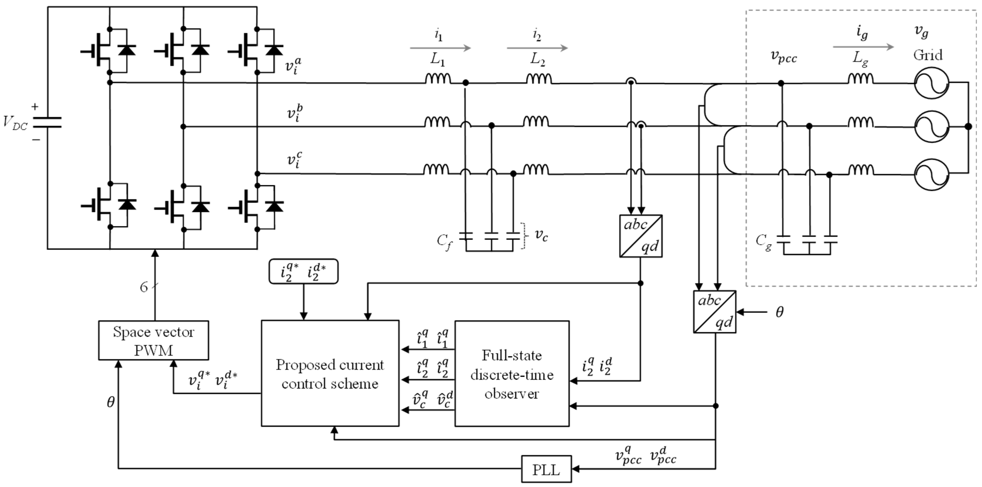
A configuration of three-phase LCL-filtered GCI with LC grid impedance is presented in
Figure 1. The proposed control scheme utilizes only the measurement of the PCC voltages and grid-side currents. For the configuration of multiple GCIs, a similar LCL-filtered GCI is interfaced in parallel to the PCC. The proposed current control method is established by an incomplete state feedback control strategy by eliminating the feedback term for the unmeasured state. The reference voltages derived from the current controller are provided to the GCI via the space vector PWM. In
Figure 1,
is the inverter-side current,
is the grid-side current, and
is the grid inductance current. In addition,
,
,
,
, and
represent the DC-link voltage, the inverter voltage, the capacitor voltage, the PCC voltage, and the grid voltage, respectively. In the figure,
and
are the LCL filter inductances,
is the grid inductance,
is the LCL filter capacitance, and
is the grid capacitance. The symbol ‘^’ represents the estimated state variables and the symbol ‘*’ represents the reference variables. Additionally, the superscripts
a,
b, and
c denote three-phase variables, and the superscripts
q and
d correspond to the variables in the synchronous reference frame (SRF). To synchronize the inverter with the grid, the phase angle of the grid voltage is detected through the phase-lock loop (PLL)-based method [
28].
When the LC grid impedance exists, the state-space model of a GCI system is expressed in the SRF as follows [
27]:
where
is the system state vector and
and
are the input and grid voltage vector. The system matrices
A,
B,
C, and
D are represented as
The state-space model in (1) and (2) is discretized employing the sampling time,
, as follows:
where
,
,
, and
The control input,
(
k), is obtained at each sampling instant of
k-th step. However, in digital processors, the control input,
(
k), can be executed only at the next sampling instant of (
k + 1)-th step, which results in a computation delay equal to one sampling period [
29]. Therefore, one-step delay must be incorporated into the system model to ensure more accurate control performance. The system model considering one-step delay is expressed using a new state variable,
(
k), as follows:
3. Proposed Current Control Scheme with Complex Grid
The proposed current control method comprises an incomplete state feedback control and a full-state current-type observer. To achieve the purposes of reference tracking and harmonic rejection, integral feedback control and resonant control are incorporated in a current controller. Also, the system state variables are determined through the full-state observer with only the minimum measured value of the PCC voltages and the grid-side currents. These estimated system state variables are utilized to realize the incomplete state feedback controller.
To ensure reference tracking without steady-state current error, the state-space system model incorporates an integral control term. Moreover, to suppress low-order harmonic components resulting from the distorted grid, resonant control terms are also augmented. The integral and resonant control terms are described as follows [
30]:
where
is the grid-side current error vector and
is the reference current vector. The state-space matrices are represented as
The state equations in (9) and (10) are integrated as
where
denotes the state vector of the integral and resonant control terms,
:
By combing (7), (8), and (13), the whole system model is given as follows:
The optimal gain-of-state feedback control matrix,
, is derived through the linear quadratic regulator (LQR) approach as follows [
12]:
where
,
is a positive semi-definite matrix, and
is a positive definite matrix. The weighting matrices for the LQR are selected through successive simulations and experiments to obtain the appropriate gain matrix,
. The mathematical calculations for the LQR approach are obtained with the MATLAB (Matlab Control System Toolbox version 10.11) function “dlqr”.
Nevertheless, when LC grid impedance is present, precise measurement or estimation of the current through the grid inductance is difficult. Consequently, it is difficult to realize a full-state feedback control. Therefore, the feedback control method excluding the states for the grid inductance current is applied as follows [
31]:
where
is the gain vector corresponding to the system state feedback control,
is the gain vector corresponding to one-step delay output feedback control,
is the gain vector corresponding to the integral and resonant feedback controls. To avoid the unmeasurable state feedback control, the gains
, and
are set to zero in
because they are the gains related to the grid inductance current variables
and
. Finally, the feedback control is developed as
To execute an incomplete state feedback controller while minimizing the number of measuring instruments, a full-state current-type observer is applied for estimating the essential state variables such as
,
, and
. The state-space model of a GCI system is formulated with six state equations as follows:
where
is the essential system state vector,
is the PCC voltage vector, and the matrices
,
,
and
are represented as
The state-space model in (20) and (21) is discretized with the sampling time,
, as follows:
where
,
,
, and
From (24) and (25), a full-state current-type observer can be expressed as follows:
where
is the observer gain and
is the first estimated state vector from the dynamics of the system [
12].
4. Stability Assessment of Multiple Grid-Connected Inverters
As previously mentioned, multiple GCIs can effectively increase the power capacity supplied to the grid. However, controlling multiple-GCI systems requires a particular consideration compared to a single-GCI system since the interactions among inverters exist because of LC-type grid impedances. A portion of the grid-injected current from each inverter flows through the output impedance of the other inverter.
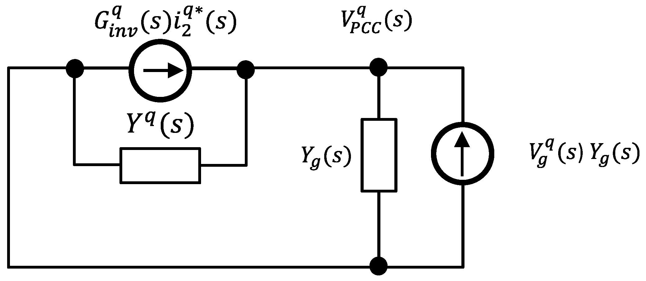
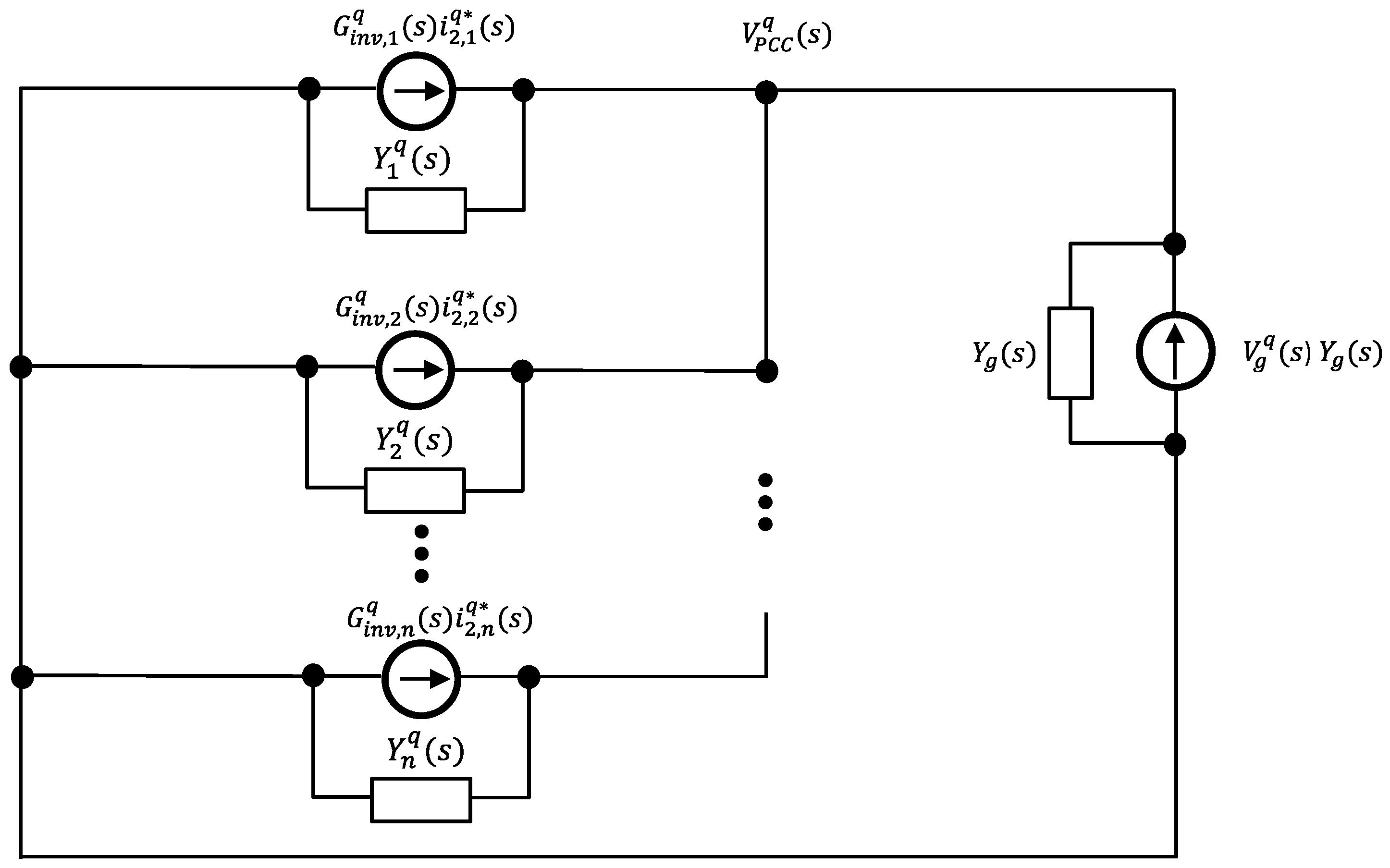
The multiple-GCI systems are represented as a simplified Norton equivalent circuit and an admittance-based stability assessment is conducted in this section.
Figure 2 indicates the simplified Norton equivalent circuit of the closed-loop inverter model for a single-GCI system with grid impedance (denoted by admittance,
). In
Figure 2,
stands for the output admittance of the inverter and
indicates the closed-loop transfer function of the inverter. The admittances and closed-loop transfer function are described as follows:
Figure 3 shows the Norton equivalent circuit of the closed-loop inverter system model for multiple GCIs. In the variables such as
or
, the subscript ‘
n’ represents total number of parallel-connected inverters [
18]. The transfer function
denotes the current source of the
j-th inverter, and
denotes the current source derived from the grid voltage. Then, the grid-side current of the
j-th inverter and the PCC voltage are formulated as follows:
From (31) and (32), the grid-side current,
, can be expanded as follows:
where
represents the reference tracking performance of the j-th inverter,
represents the interaction of the k-th inverter and the influence on the j-th inverter, and
indicates the influence of the grid voltage on the j-th inverter.
If all inverters are equivalent, it yields
According to the stability analysis in [
21], if the denominator of (32) approaches zero, multiple-GCI systems can become unstable because the magnitudes of the transfer functions
, and
are significantly increased. When the denominator
in the transfer functions is equal to zero, the magnitudes of
and
are equal and their phase difference is 180°. In other words, to maintain the transfer functions
,
, and
in a stable region in multiple-GCI systems, the phase difference between
and
should be kept away from 180° in regions where their magnitudes are equal. In addition, the magnitudes of the transfer functions
and
should remain below 0 dB throughout all frequency ranges in order to avoid the influences from the other inverter operations as well as the PCC voltages.
5. Simulation Results
For comprehensive assessment of the current controller capability and the stability of multiple GCIs operating with LC grid impedance and distorted grid conditions, the simulations are carried out using the PSIM software for both a single-GCI configuration and a multiple-GCI configuration. Additionally, an admittance-based stability assessment of the multiple GCIs is performed with MATLAB (Matlab Control System Toolbox version 10.11) to verify the stability and robustness of the system. The parameters for the multiple GCIs are represented in
Table 1. Both the simulation and experimental tests are carried out with a grid inductance of 3 mH in order to validate the proposed control strategy under weak grid conditions [
32,
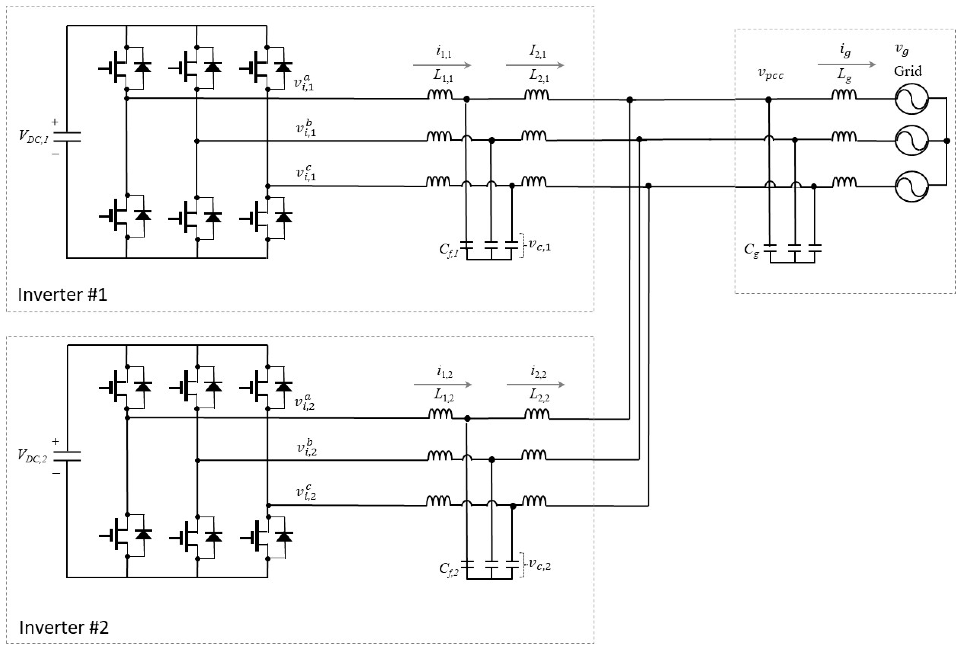
33]. In this study, two GCI systems are considered for both simulation and experimental tests, as shown in
Figure 4. Regarding the variables in
Figure 4, the first subscript follows the same definition as provided in
Section 2, while the second subscript and the symbol “#” denotes the inverter number.
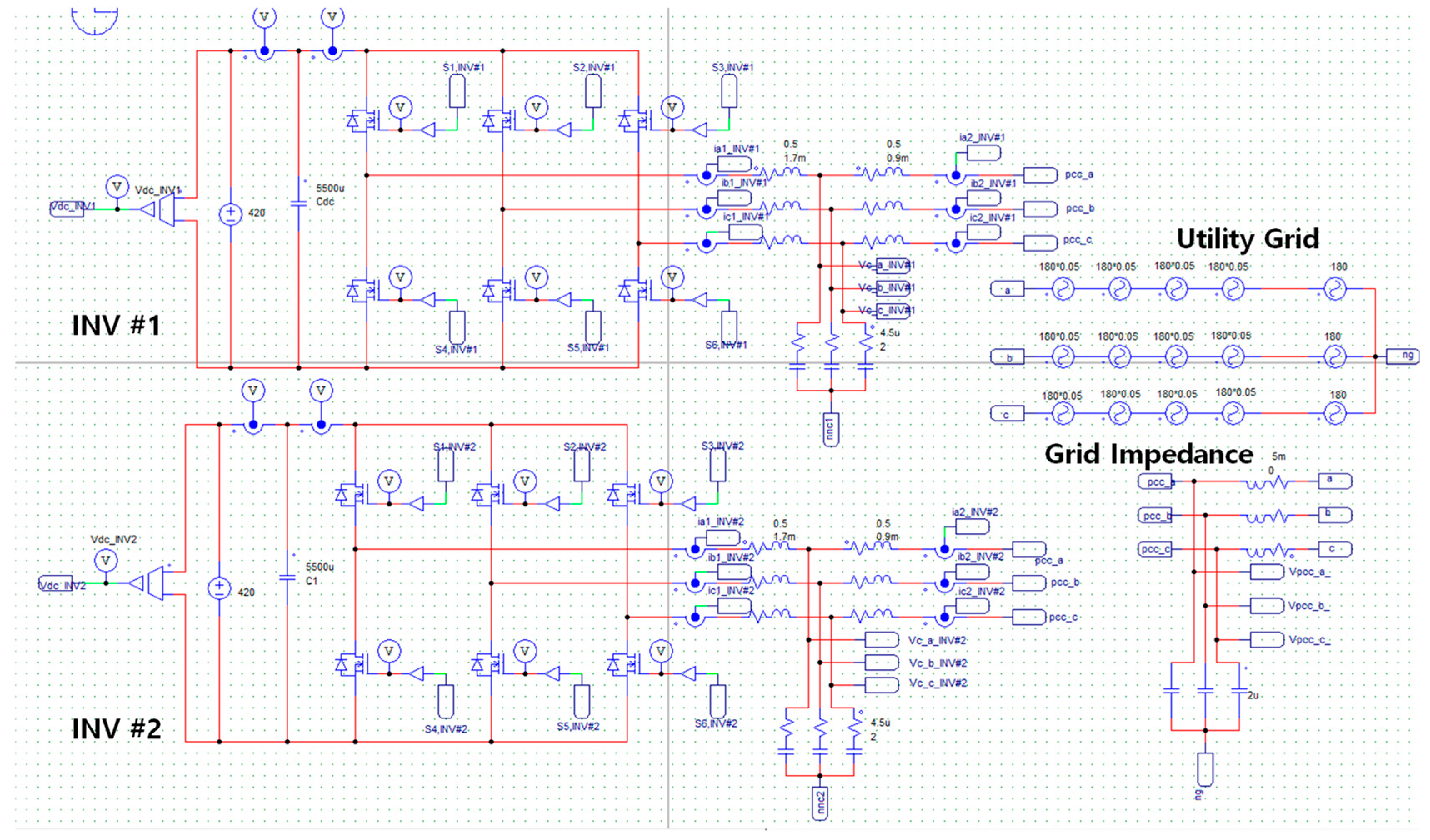
Two GCIs are tied in parallel to the utility grid and have identical controllers and LCL filter parameters.
Figure 5 presents the PSIM schematic to simulate two GCI systems for comprehensive assessment of the current controller. Two GCIs are tied in parallel to the utility grid and have identical controllers and LCL filter parameters. In this simulation, the inverter-side currents, capacitor voltages, grid-side currents, PCC voltages, and grid voltages are monitored to evaluate the performance of the proposed control scheme.
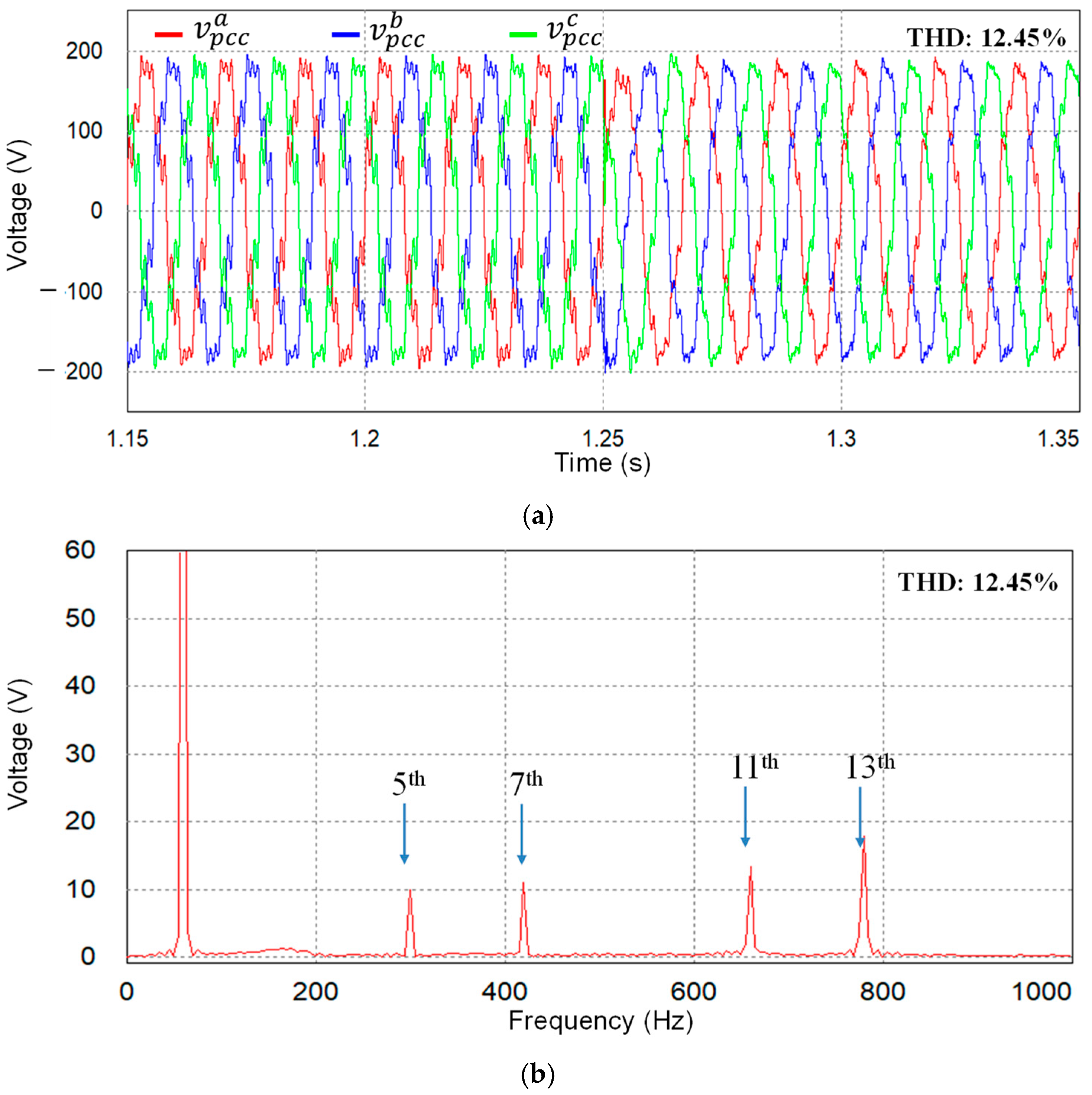
Figure 6a shows the simulated three-phase PCC voltages under LC grid impedance and grid distortion. In the simulation tests, the inductive component of the LC grid impedance is set to 3 mH, while the capacitive component is set to 3 µF. To emulate a distorted grid environment, the 5th-, 7th-, 11th-, and 13th-order harmonics are embedded in the grid voltages, with their magnitudes calibrated to 5% of the fundamental voltage. Resultant PCC voltages exhibit notably distorted waveforms with the THD value of 12.45% due to the combined effect of the inherent resonant behavior of the LC grid impedance and the introduced harmonic distortion.
Figure 6b presents the fast Fourier transform (FFT) plot of
a-phase PCC voltage, in which certain harmonic components are further amplified due to the LC grid impedance.
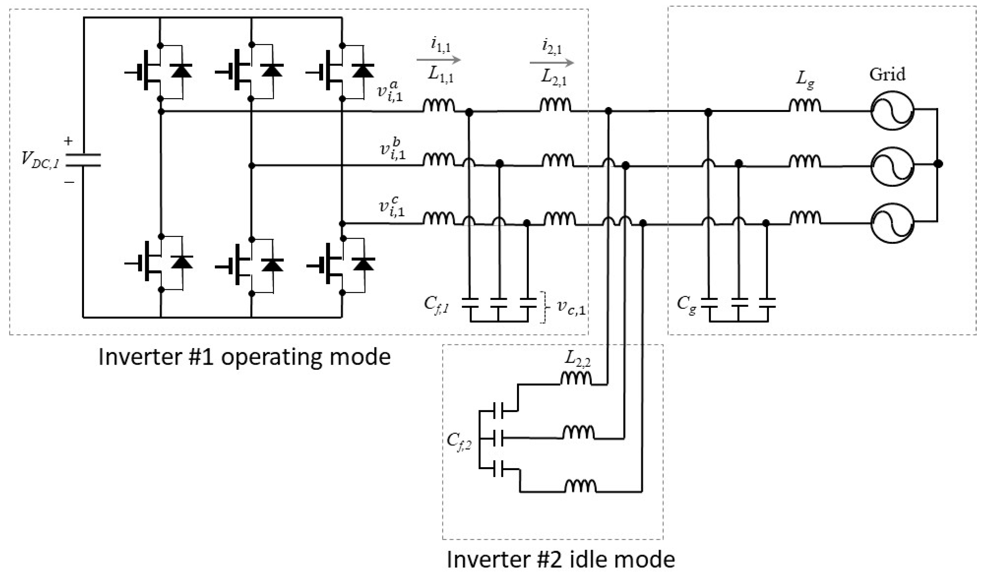
When only one GCI is in operation while the other remains idle, the overall grid admittance seen by the operating inverter is altered.
Figure 7 shows the configuration in which inverter #1 is in operation to inject active power into the utility grid, whereas inverter #2 is still in idle mode. In this situation, the LCL filter of inverter #2 functions as another impedance connected to the LC grid impedance. Consequently, the overall grid admittance, including the effect of filter capacitance and the inductance of idle inverter #2, is expressed as follows:
To assess the stability based on the admittance-based analysis,
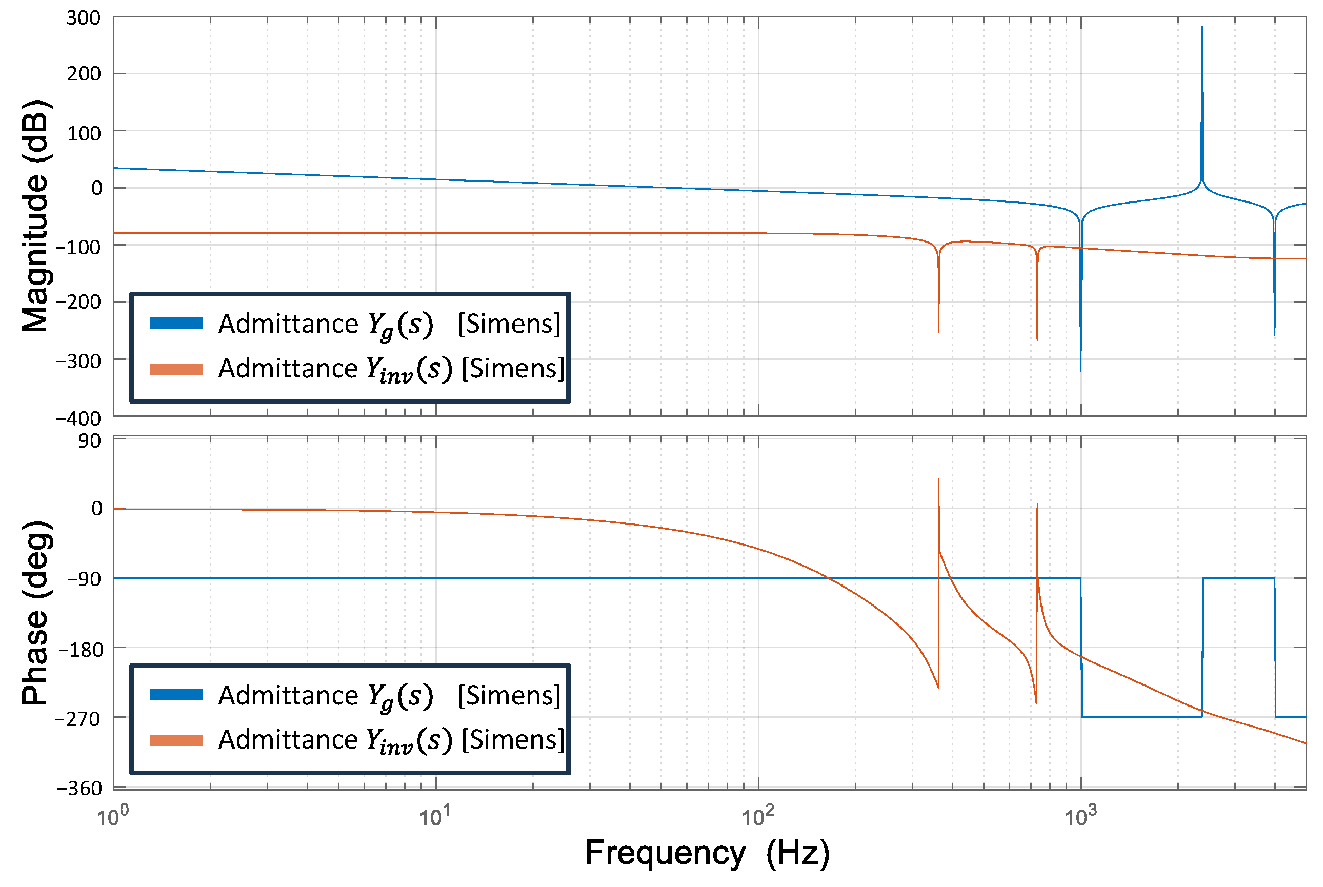
Figure 8 represents the frequency responses of the multiple-GCI systems when inverter #1 is active and inverter #2 remains in idle mode, as previously demonstrated in
Figure 7. In this figure,
represents the grid impedance as expressed in (37) and includes the LC-type grid impedance as well as the filter capacitance and inductance of idle inverter #2. Meanwhile,
denotes the output admittance of inverter #1. In the magnitude plot, the grid admittance and the output admittance of inverter #1 intersect at four different points, in which the phase differences are 103°, 77°, 158°, and 22°, respectively, which confirms that the inverter system remains in a stable range. High-magnitude peaks appear in the frequency response because the internal resistances of the LCL filter components are neglected in the modeling process described in
Section 2. However, using ideal LCL filter components without considering resistive elements does not affect the admittance-based stability analysis.
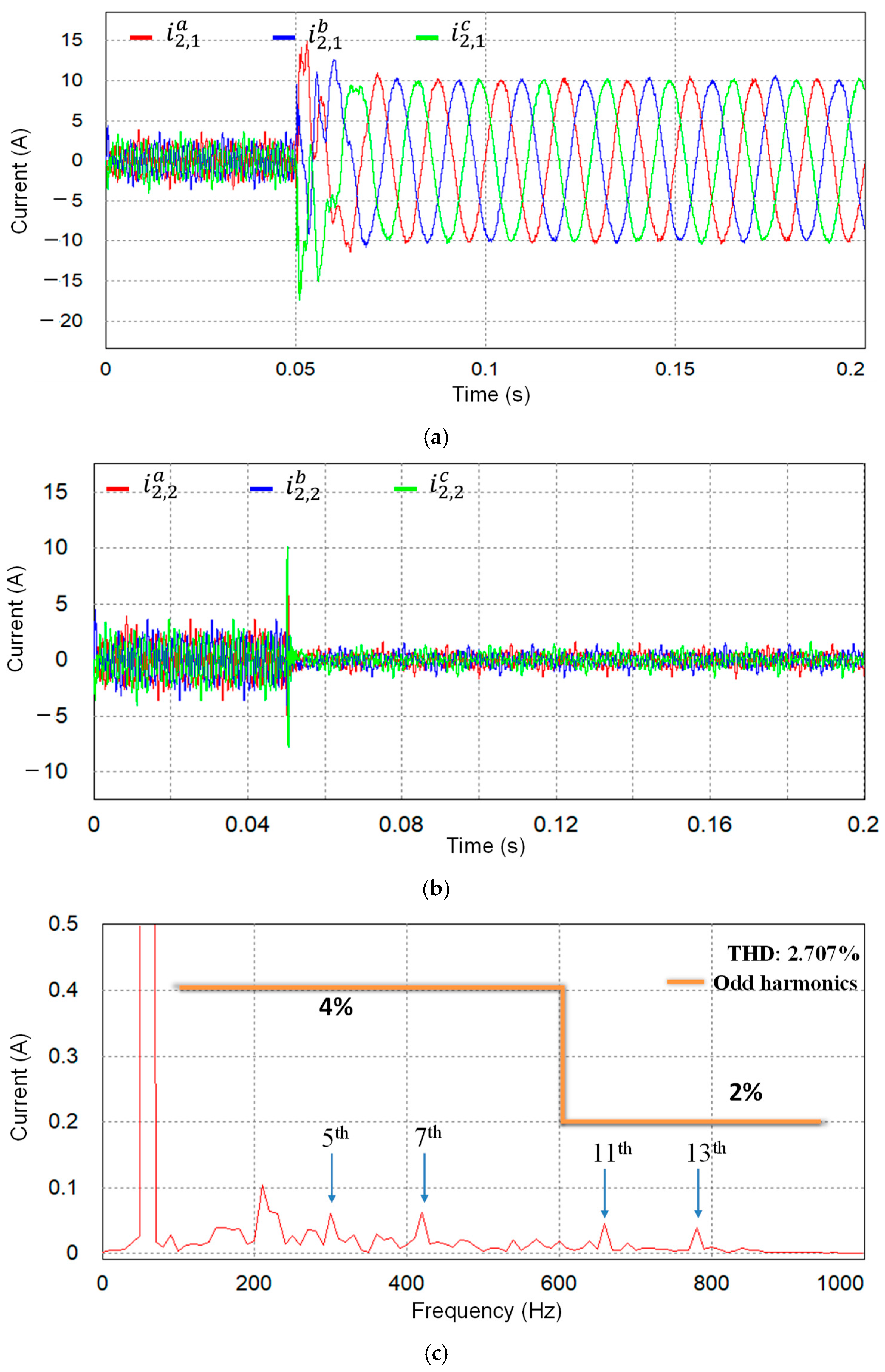
Figure 9 represents the capability of the proposed current controller when only inverter #1 is operating, while inverter #2 remains in idle mode under harmonic distortion of PCC voltages with the LC grid impedance. The three-phase grid-side currents of inverter #1 and inverter #2 are represented in
Figure 9a and
Figure 9b, respectively. Before 0.05 s, both inverters are idle. At 0.05 s, only inverter #1 starts operating with the
q-axis reference current of 10 A. After a short transient period, the grid-side currents remain high-quality sinusoidal currents at a steady state with a low THD of 2.707%. The FFT plot of the
a-phase grid-side current in
Figure 9c demonstrates compliance with the requirements of IEEE Std. 1547-2003 [
4]. These results verify that inverter #1 can supply high-quality current regardless of the change in the grid impedance due to the existence of other parallel-connected inverters.
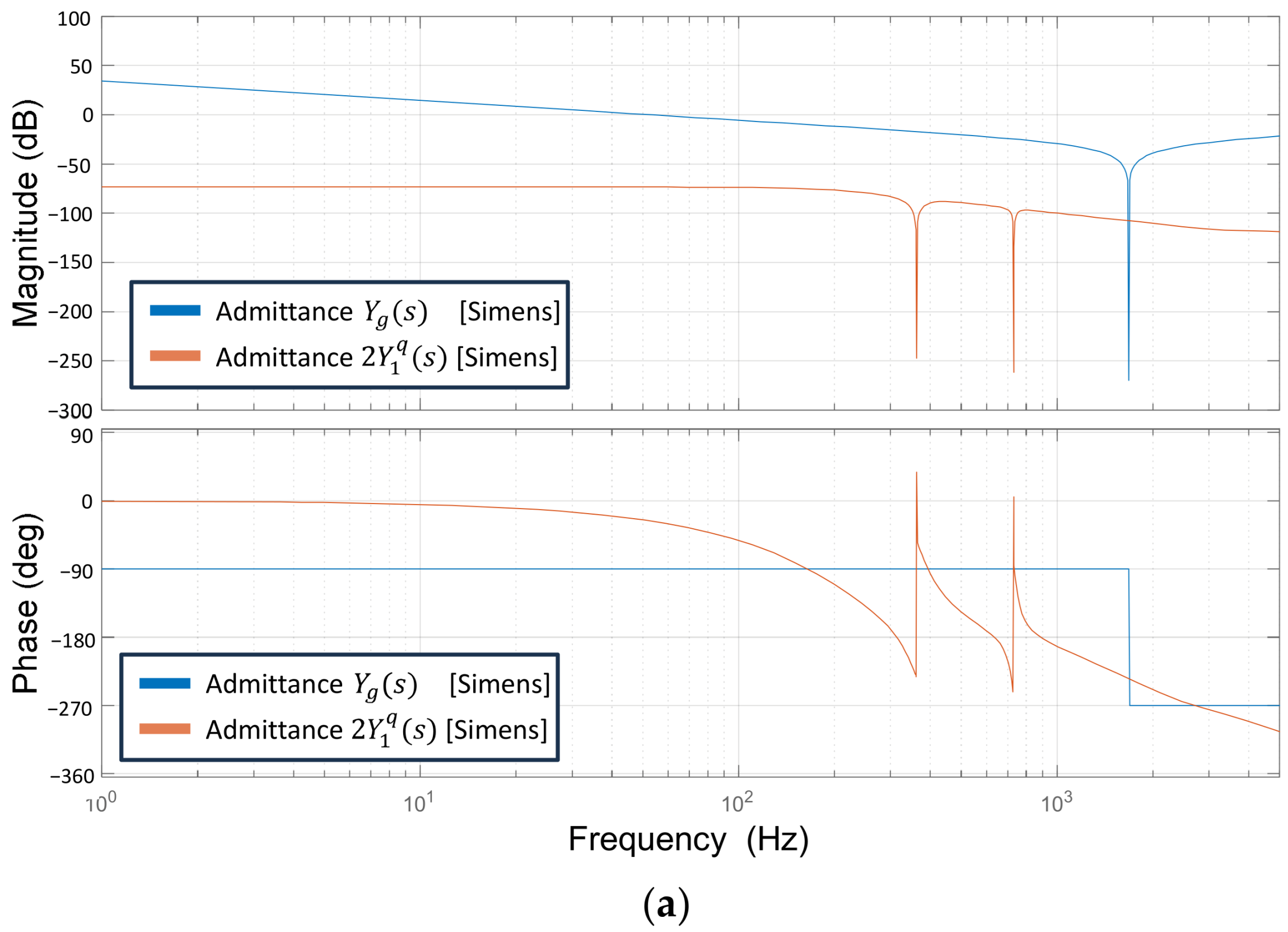
When both inverters are operating as shown in
Figure 4, the magnitude and phase responses of the output admittance and the grid impedance are illustrated in
Figure 10a. Since both inverters have the same system configuration, the total output admittance is represented as
. When both inverters are working, the grid impedance is simply presented as (26). The plot reveals two intersection points of
and
, at which the phase differences are 145° and 35°. Since the phase difference between
and
is kept away from 180° at the point where their magnitudes are equal, the transfer functions
remain in the stable region.
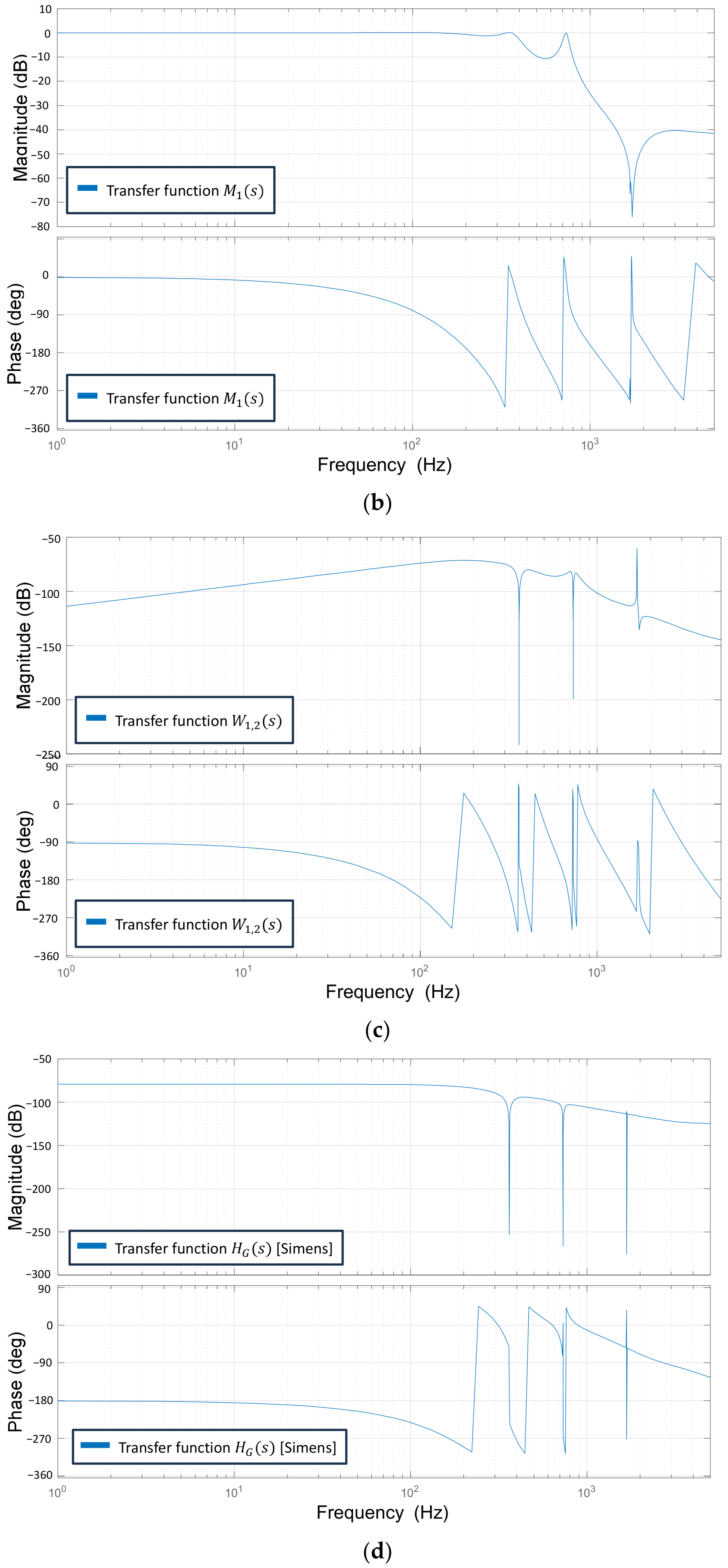
To assess the reference tracking capability of inverter #1, a Bode diagram of the transfer function
is presented in
Figure 10b. In low-frequency regions, both the magnitude and phase converge to 0 dB and 0°, respectively, which implies that the proposed controller effectively tracks the reference current.
The Bode plot of the transfer function
, which describes the influence of inverter #2 on the output current of inverter #1, is illustrated in
Figure 10c. At all frequencies, the magnitude of
remains below 0 dB, indicating that the output current of inverter #1 is unaffected by inverter #2.
A Bode plot of the transfer function
, which describes the impact of the grid voltage on the output current of inverter #1, is shown in
Figure 10d. The magnitude plot always remains below 0 dB for all frequency ranges. In particular, the magnitude decreases sharply at the 6th and 12th harmonic frequencies, which indicates that the harmonic distortion of the grid voltage is effectively compensated. Moreover, due to the resonance of the LC grid impedance, the frequency response of the grid admittance,
, exhibits a sharp peak around the resonance frequency of 1670 Hz.
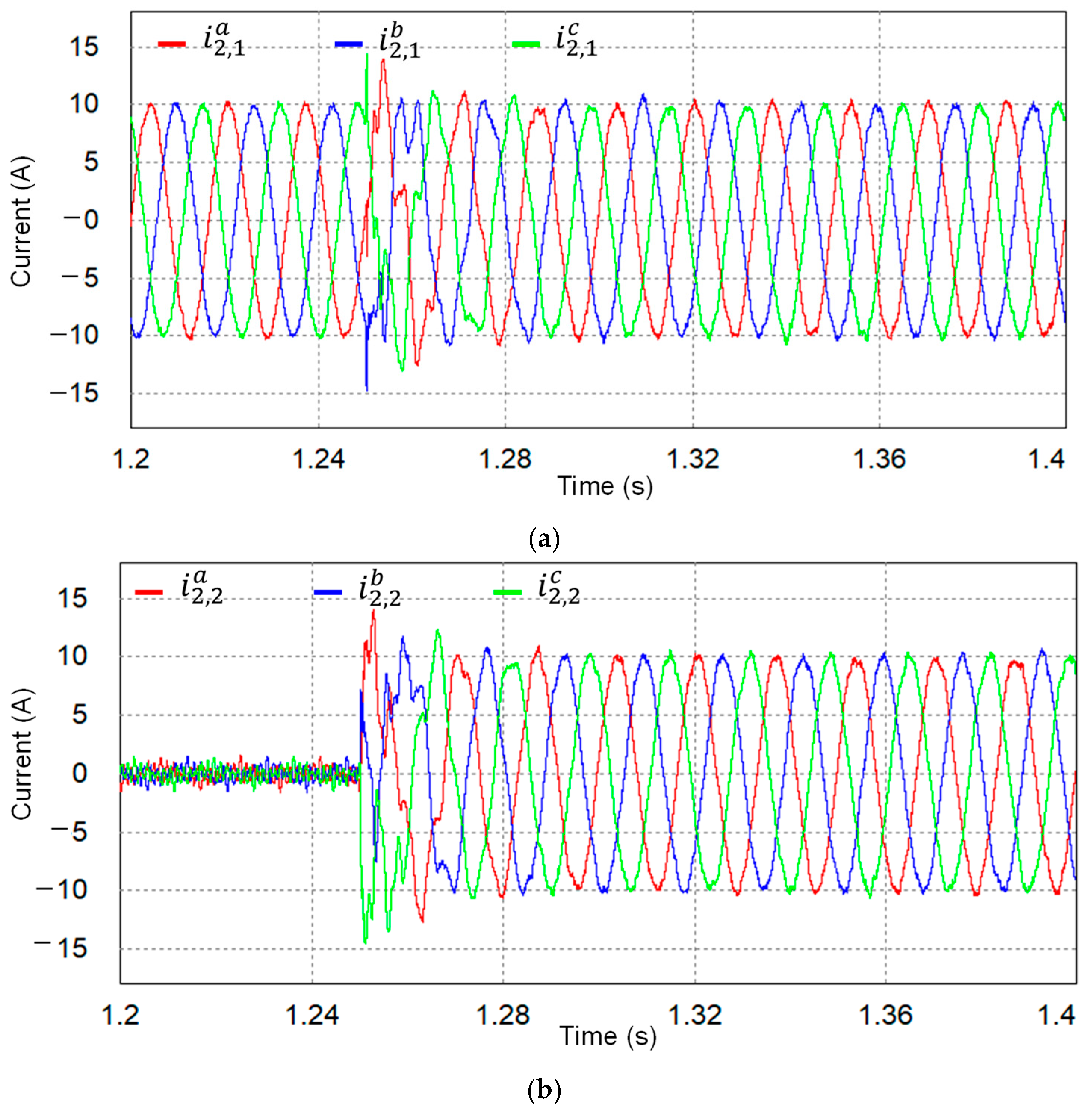
Figure 11 presents the simulated current responses of multiple GCIs when both inverter #1 and inverter #2 operate under distorted PCC voltages. Before 1.25 s, only inverter #1 is operating. Inverter #2 starts operating from idle mode at 1.25 s. In both inverters, the
q-axis reference currents are set to 10 A. Three-phase grid-side currents of inverter #1 and inverter #2 are shown in
Figure 11a,b, respectively. Even though the current responses of inverter #1 momentarily exhibit a transient response with overshoot due to the start-up of inverter #2, inverter #1 rapidly settles back to stable operation.
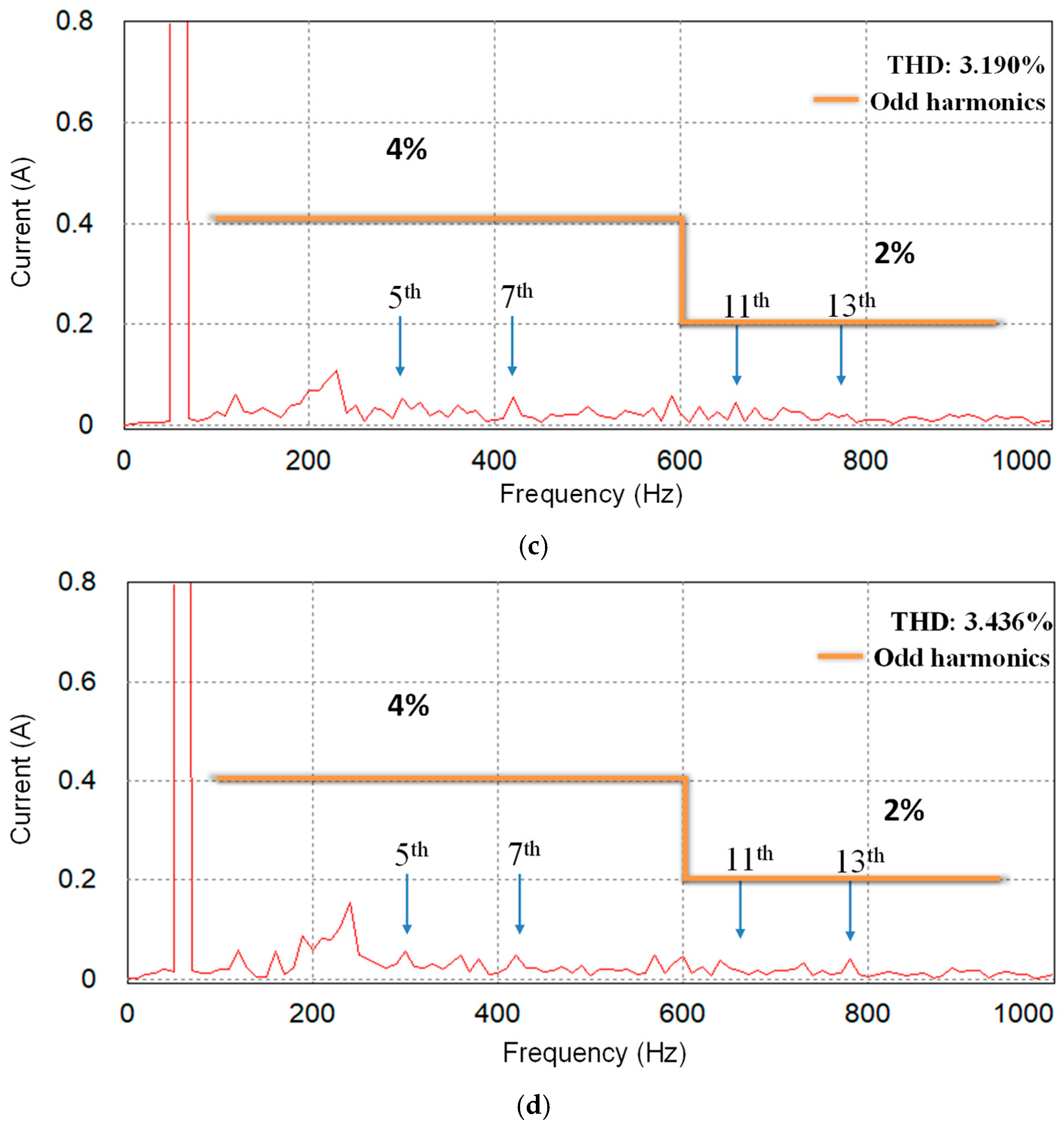
Figure 11c,d display the FFT plots of
a-phase grid-side currents for two GCIs. The results prove that both GCI systems maintain high-quality sinusoidal currents with the proposed control strategy despite harmonic distortion in the PCC voltages and the dynamic interaction between parallel inverters. The measured THD values are 3.190% for inverter #1 and 3.436% for inverter #2, respectively.
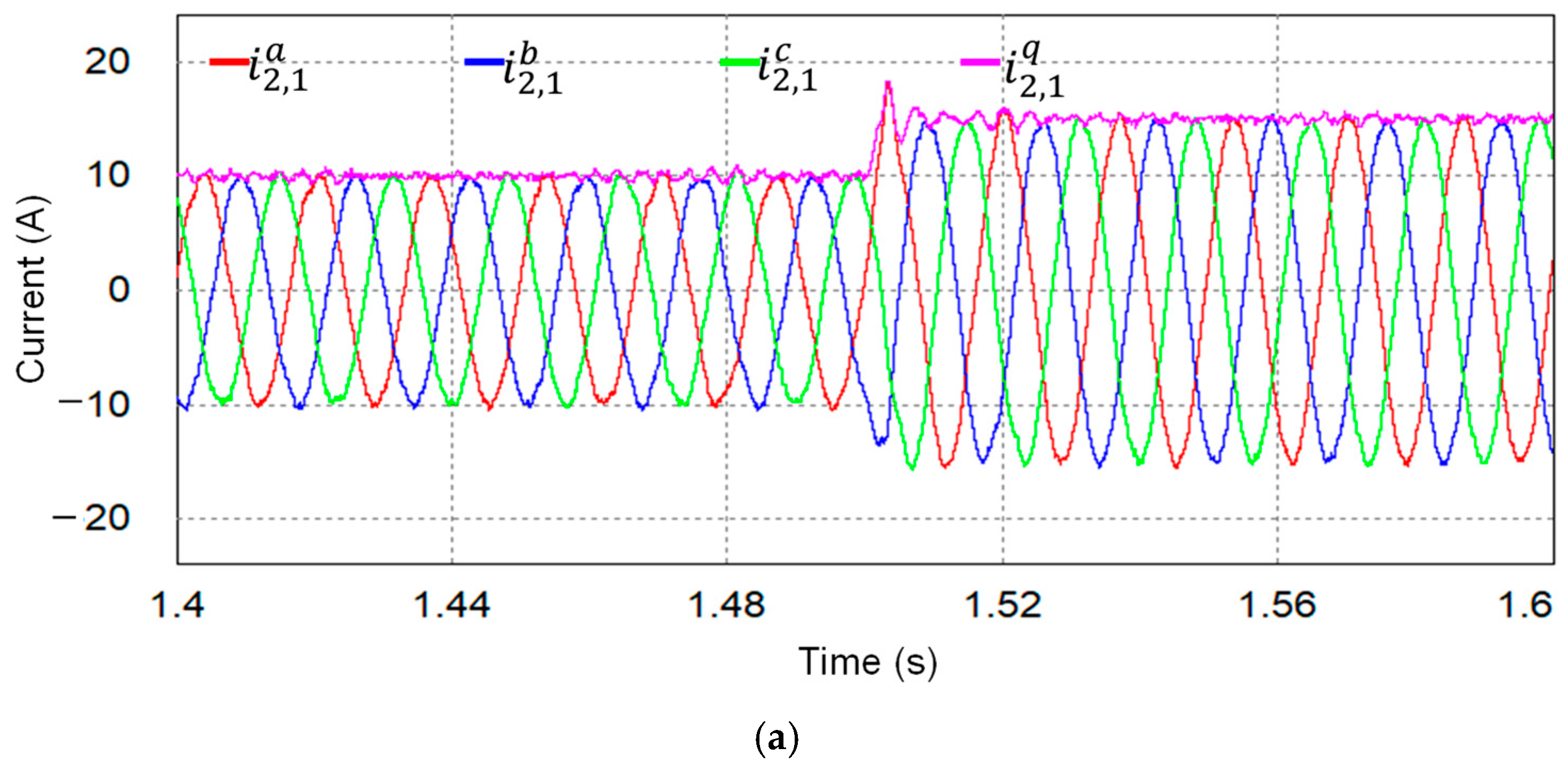
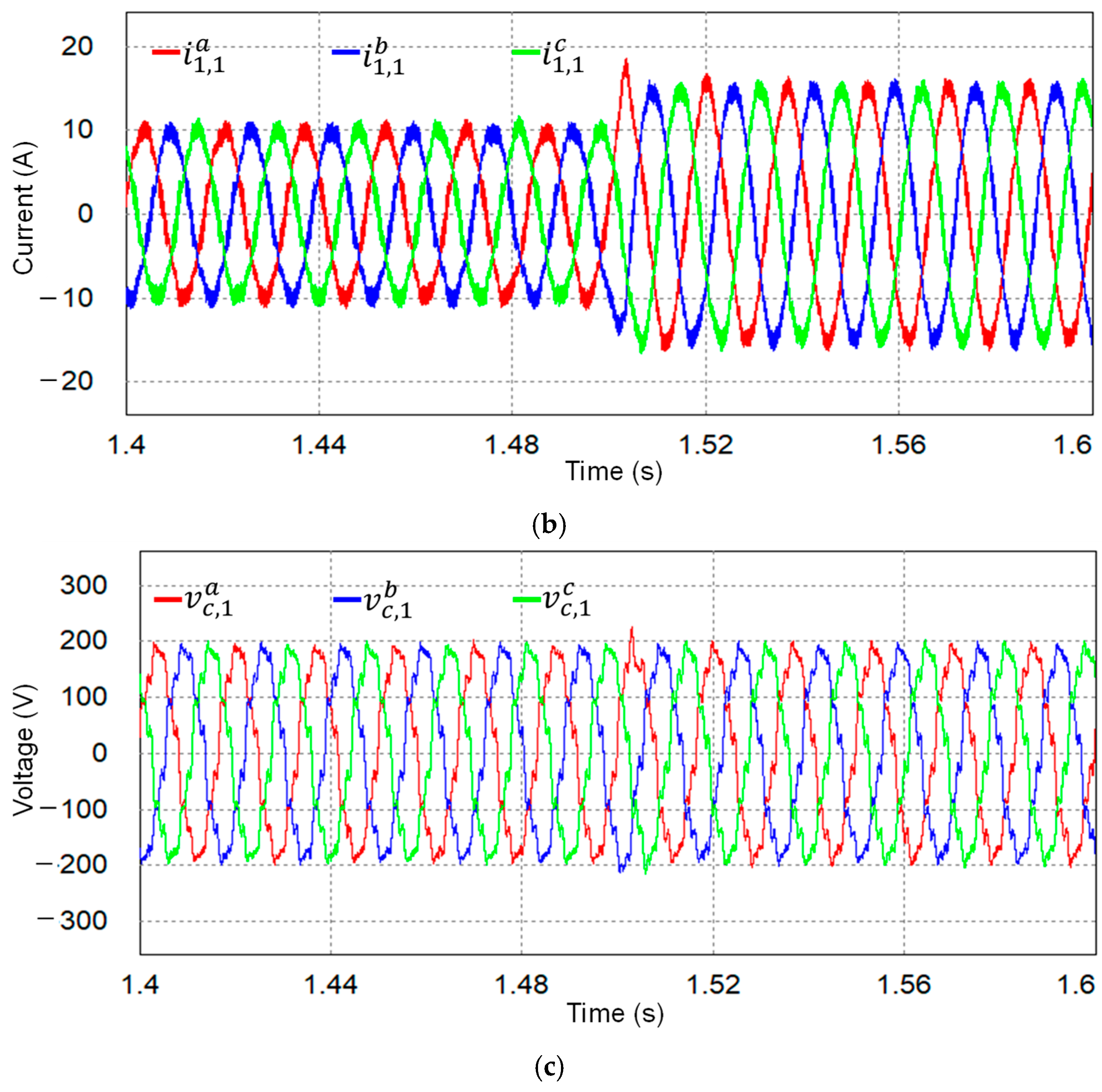
The transient performance of multiple GCIs is evaluated through the simulation tests as shown in
Figure 12, in which the inverters #1 and #2 operate under distorted PCC voltages. A step variation in the reference current from 10 A to 15 A is applied at 1.5 s.
Figure 12a–c show the grid-side currents, inverter-side currents, and capacitor voltages of the LCL filter for inverter #1 when both inverters are working.
Figure 12 validates that the proposed current control strategy has a rapid transient response.
6. Experimental Results
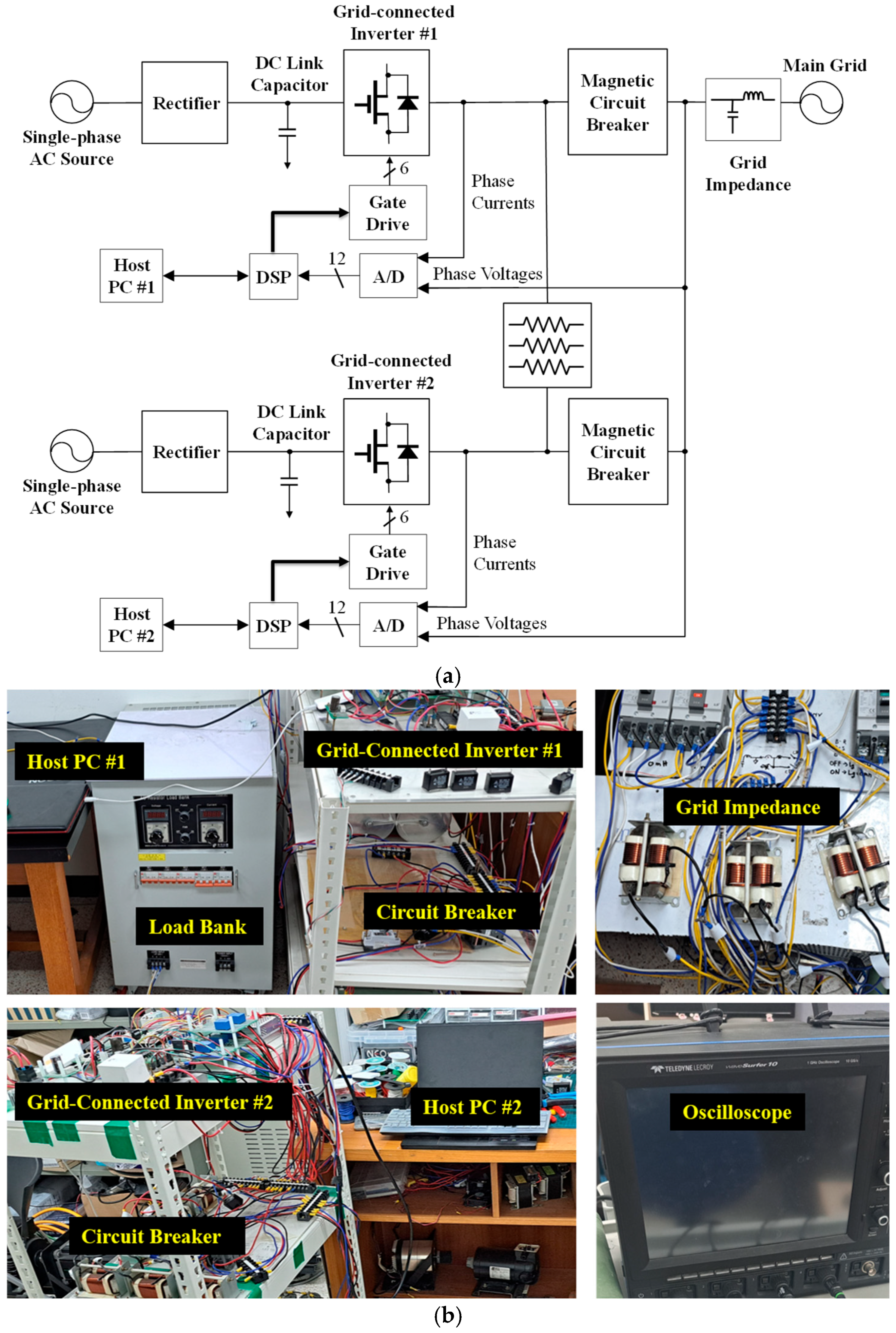
The theoretical stability analysis and the performance of the proposed current control method are experimentally validated utilizing the laboratory prototype of a three-phase multiple-GCI system, as depicted in
Figure 13.
Figure 13a presents a block diagram of the overall experimental system, which consists of two LCL-filtered inverters, magnetic contactors, load banks, two DSP-based controllers, grid-side current sensors, voltage sensors, the utility grid, and LC grid impedances. The two inverters are tied in parallel to the PCC via the LCL filter and the magnetic circuit breaker. A 32 Ω load bank is connected to the PCC as a resistive load for the system. The DC source voltage for the GCI system is supplied from the AC source using a rectifier. To implement the proposed algorithm in real time with a sampling frequency of 10 kHz, two DSP-based TMS320F28335 control boards are utilized for each inverter. The measured signals from the PCC voltage and grid-side current sensors are sent to the DSP board using the analog-to-digital converters. The control signals are transferred from the DSP board to the inverter through the gate driver circuit.
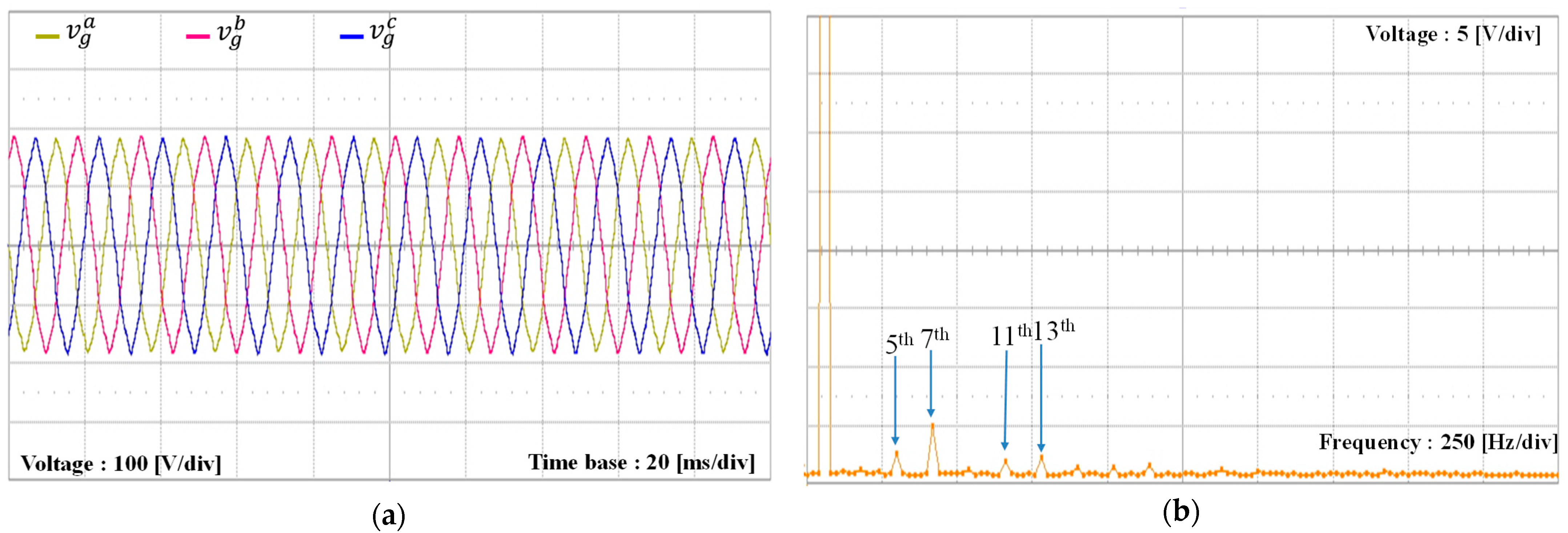
Figure 13b presents a photograph of the experimental setup, which consists of two LCL-filtered inverters. The oscilloscope and current probe are used to display and store the measurement waveforms.
Figure 14a represents the three-phase voltages of the utility grid used in the experiment. Although the grid impedance is not present, significant low-order harmonic distortion is present in the grid voltage waveforms. As depicted in
Figure 14b, the FFT plot for the
a-phase grid voltage indicates the presence of noticeable harmonic components at the 5th, 7th, 11th, and 13th orders.
To verify the feasibility of the proposed current control method, the experiments are performed in a distorted grid environment with the LC grid impedance, incorporating the grid inductance of 3 mH and the grid capacitance of 3 µF.
Figure 14 displays the distorted grid voltages, and
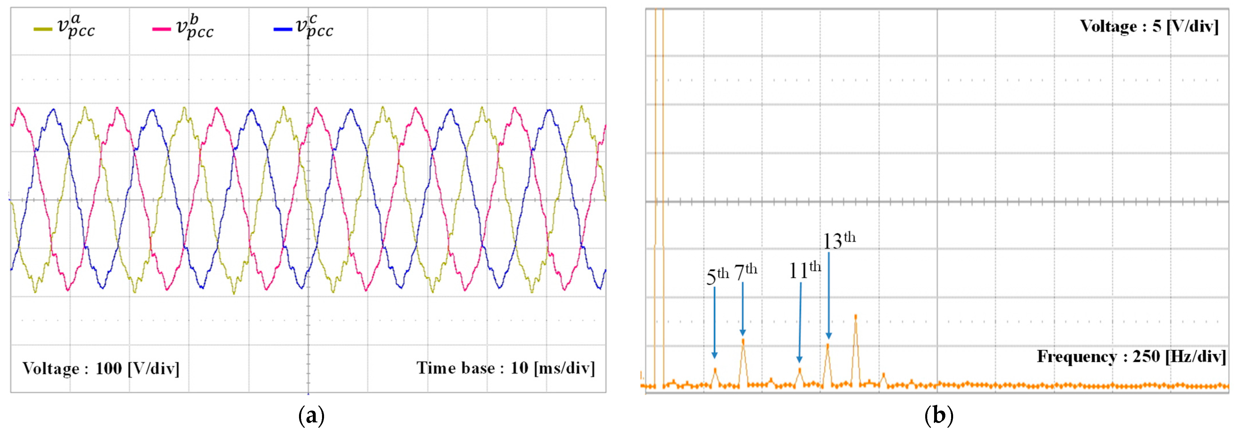
Figure 15 represents the PCC voltages further distorted by the LC grid impedance. As compared to
Figure 14a, the PCC voltages in
Figure 15a are more distorted because of the interaction between the LC grid impedance and harmonic distortion.
Figure 15b is an FFT plot for the
a-phase PCC voltage. It is worth mentioning that the LC grid impedance not only increases the existing harmonic components but also generates additional harmonic components beyond the 5th, 7th, 11th, and 13th components. In fact, it can be observed that the 15th harmonic component is significantly amplified in
Figure 15b as compared to
Figure 14b due to the LC grid impedance.
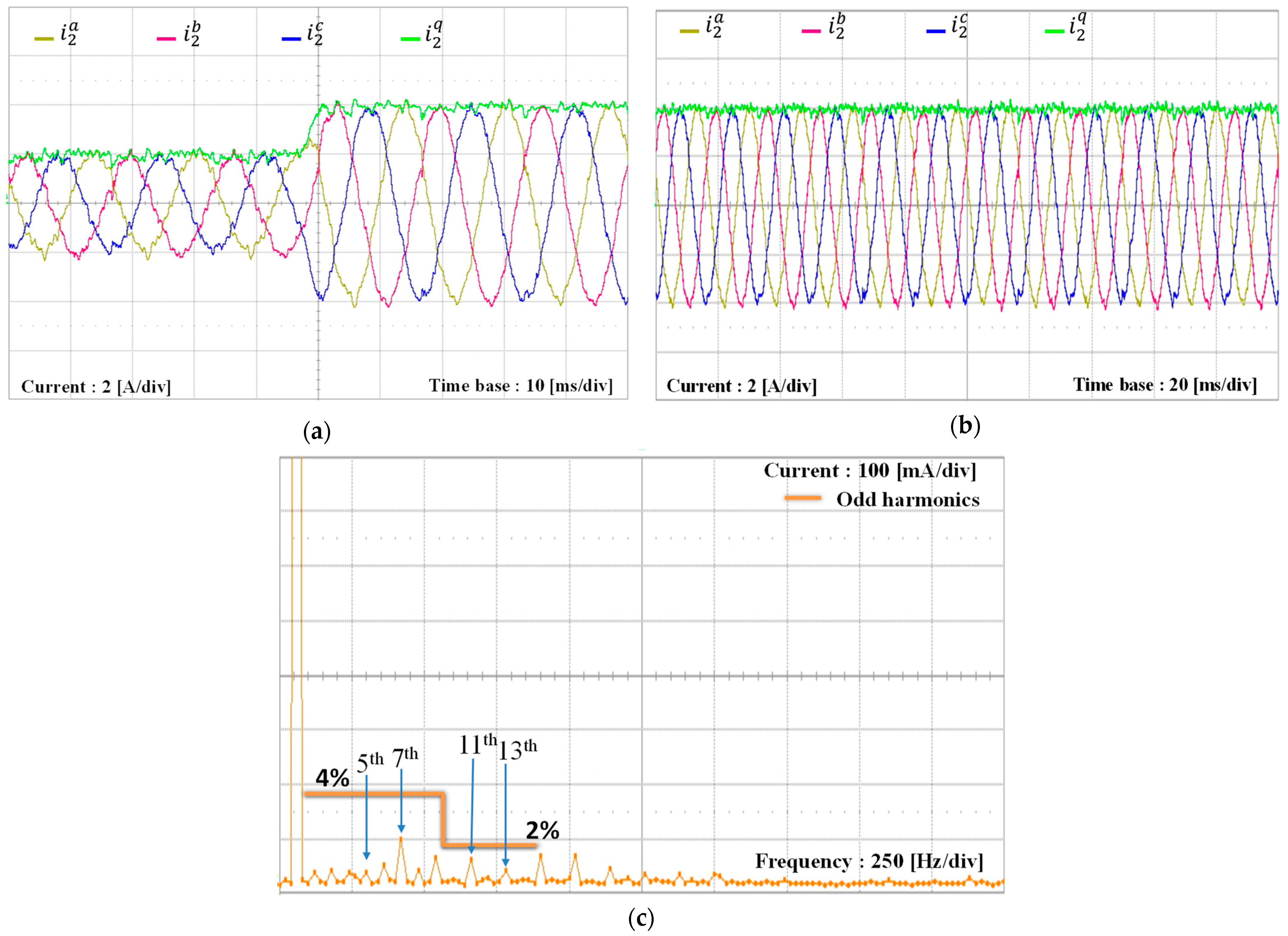
Figure 16 presents the experimental results for the proposed current controller for reference tracking performance and transient responses when a single GCI operates with the distorted PCC voltages displayed in
Figure 16.
Figure 16a presents the grid-side currents when the reference current varies from 2 A to 4 A, and
Figure 16b presents the steady-state currents with the reference current of 4 A. These results prove that the proposed controller realizes high-accuracy tracking performance, even when the reference current changes, while maintaining good sinusoidal waveforms despite the LC grid impedance and harmonic distortion.
Figure 16c presents the FFT plot for the
a-phase current from
Figure 16b with the maximum harmonic limits given in IEEE Std. 1547. It is confirmed from this plot that all harmonic components satisfy the harmonic limitation.
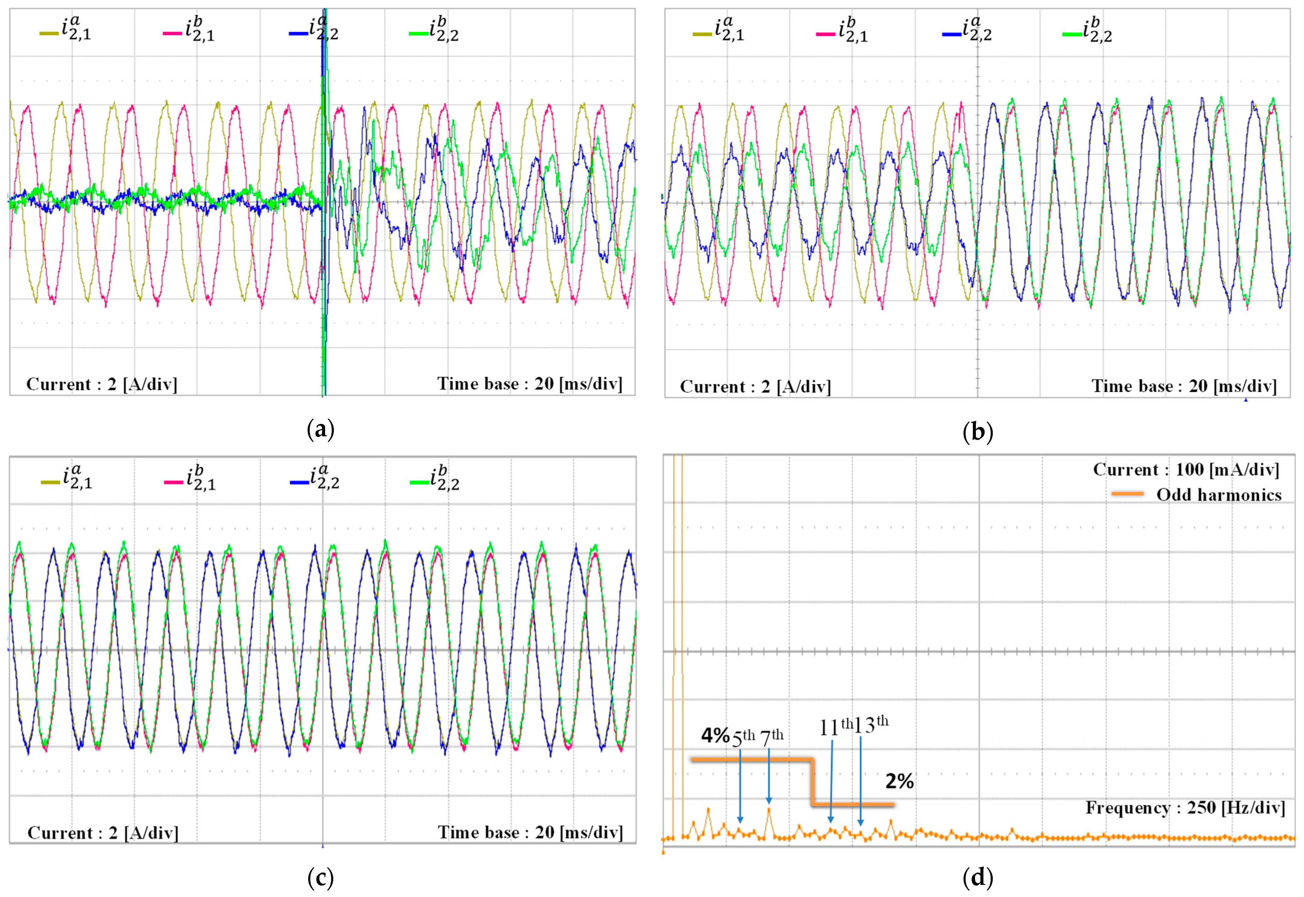
Figure 17 illustrates the experimental results for the grid-side current responses of multiple-GCI systems when inverter #1 operates and inverter #2 remains in idle mode under distorted PCC voltages like those of the simulation in
Figure 9. In
Figure 17a, inverter #1 starts supplying a current of 2 A smoothly. As mentioned earlier regarding
Figure 15b, the existence of the LC grid impedance significantly amplifies the 15th harmonic component. In addition, the LC grid impedance is modified by the filter inductance and capacitance of idle-state inverter #2 as described in (31). However, even under such a condition with distorted PCC voltages, inverter #1 operates stably. Next,
Figure 17b shows the transient response of the grid-side currents when the reference current of inverter #1 increases to 4 A. Despite the step change in the reference current, the grid-side currents maintain high quality without significant distortion or oscillation. To validate the high quality of the grid-side currents,
Figure 17c,d show the steady-state results for the grid-side currents and the FFT plot of the
a-phase grid-side current when the reference current of inverter #1 is 4 A. While ideal components and fixed distorted grid voltages are used in the PSIM simulation, the real experimental system is affected by several uncertain conditions because the real grid supply voltages are subject to variations in harmonic components and grid impedance. In addition, uncertainties caused by the LCL filter tolerance and system noise also exist. Even though this discrepancy produces slightly different harmonic amplitudes in the FFT plot, the experimental FFT results show a similar harmonic suppression capability to that of the simulation in
Figure 9c.
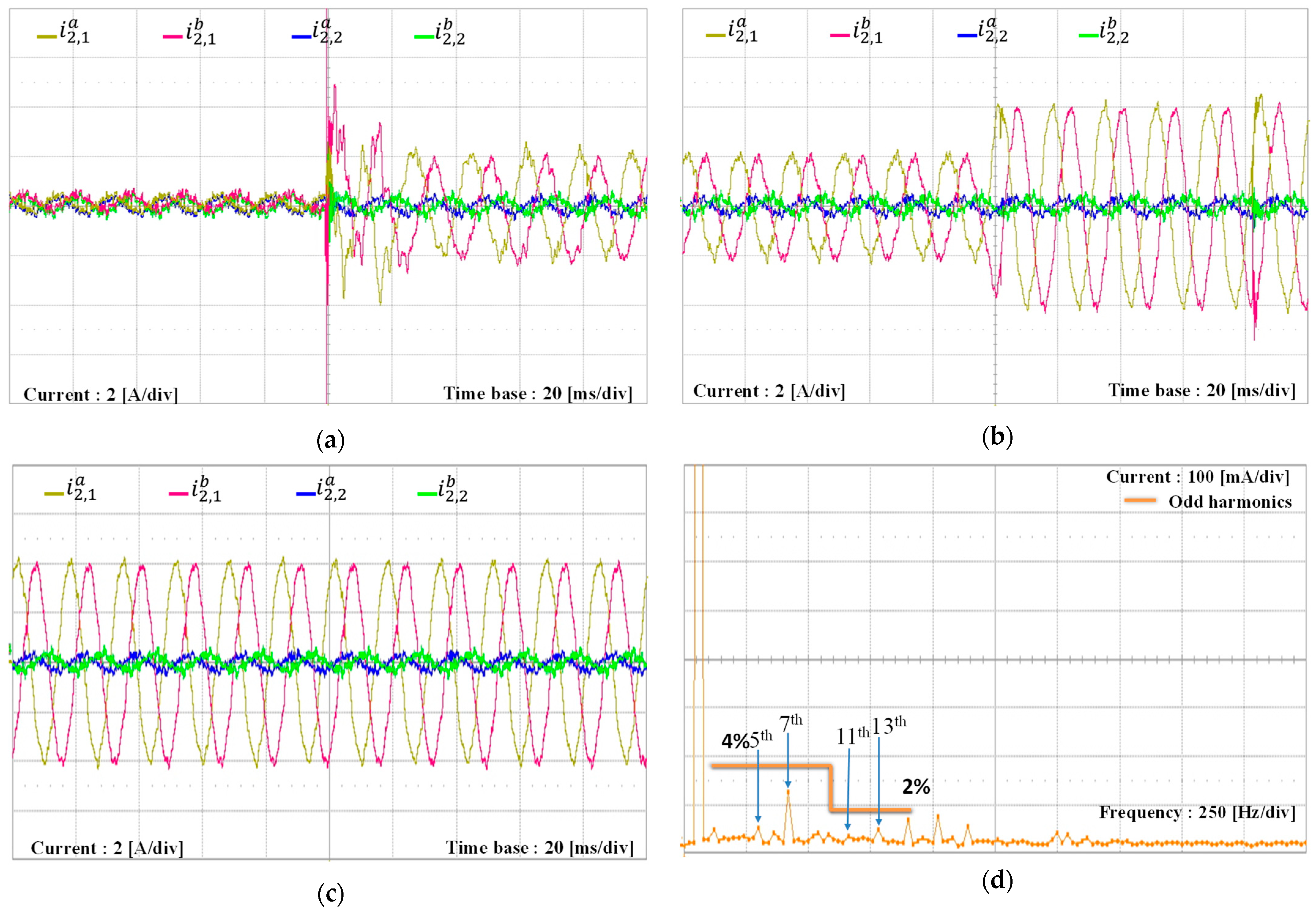
Figure 18 depicts the experimental results for current responses of multiple-GCI systems when inverter #1 and inverter #2 are operating under distorted PCC voltages. In
Figure 18a, inverter #2 starts up from idle mode with the reference current of 2 A when inverter #1 is operating with 4 A. Two multiple GCIs in parallel inject the total current of 6 A into the utility grid. In
Figure 18b, the transient response of inverter #2 is shown for a step variation in the reference current from 2 A to 4 A. This result demonstrates that inverter #1 operation is not affected by inverter #2 when both inverters are operating at the same instant. Next,
Figure 18c shows the steady-state result for two multiple GCIs, supplying the total grid-side current of 8 A into the utility grid.
Figure 18d presents the FFT plot of the
a-phase current of inverter #2. These results confirm a good harmonic suppression capability similar to the simulation result in
Figure 11d.
7. Conclusions
This study has presented a current control method and stability assessment for multiple-GCI systems under the existence of grid distortion and LC-type grid impedance. The LC grid impedance further intensifies harmonic distortion or amplifies insignificant high-order harmonic components. To ensure desired goals in the environment of multiple-GCI systems, the current controller is realized based on an incomplete state feedback control method for LCL-filtered GCIs. The proposed current control method incorporates resonant and integral control terms while eliminating the use of a feedback control term for unmeasurable states due to the existence of LC-type grid impedance. This approach effectively compensates for the harmonic distortions caused by the PCC voltages and mitigates high-frequency resonance associated with grid impedance and the GCI system. Meanwhile, the Norton equivalent circuit of the closed-loop inverter system model for multiple GCIs is presented to perform the stability assessment of multiple GCIs in complex grid conditions. Theoretical analysis demonstrates that the proposed current control strategy maintains system stability in spite of the LC-type grid impedance and interactions among multiple GCIs. The practical applicability of the proposed strategy is further attested by the PSIM simulations and experiments utilizing a 2 kW multiple-GCI prototype implemented with a DSP-based controller. In the PSIM simulation, the THD of the output current is 3.190% for inverter #1 and 3.436% for inverter #2, which indicates an excellent current control performance in multiple-GCI operations. Furthermore, the FFT results of the experimental tests in
Figure 18 show that the harmonic components are significantly suppressed, which confirms the effectiveness of the proposed current controller.
Whereas the conventional PR and full-state feedback control strategy does not explicitly consider the effects of LC grid impedance, the proposed control method incorporates the feedback terms caused by the grid impedance dynamics. Because this allows the system to maintain stable operation, the proposed scheme ensures superior performance under distorted and weak grid conditions. In addition, the proposed control strategy satisfies the power quality requirements specified in the IEEE Standard as mentioned previously.
The main strengths of the proposed control strategy are its robust performance and stable operation of multiple GCIs even under the existence of LC grid impedance and grid distortions, which is verified by an admittance-based stability assessment. Nevertheless, the proposed approach increases the system states because it needs to include additional state variables for reference tracking, harmonic compensation, and LC grid impedance modeling, which leads to slightly higher implementation complexity.
