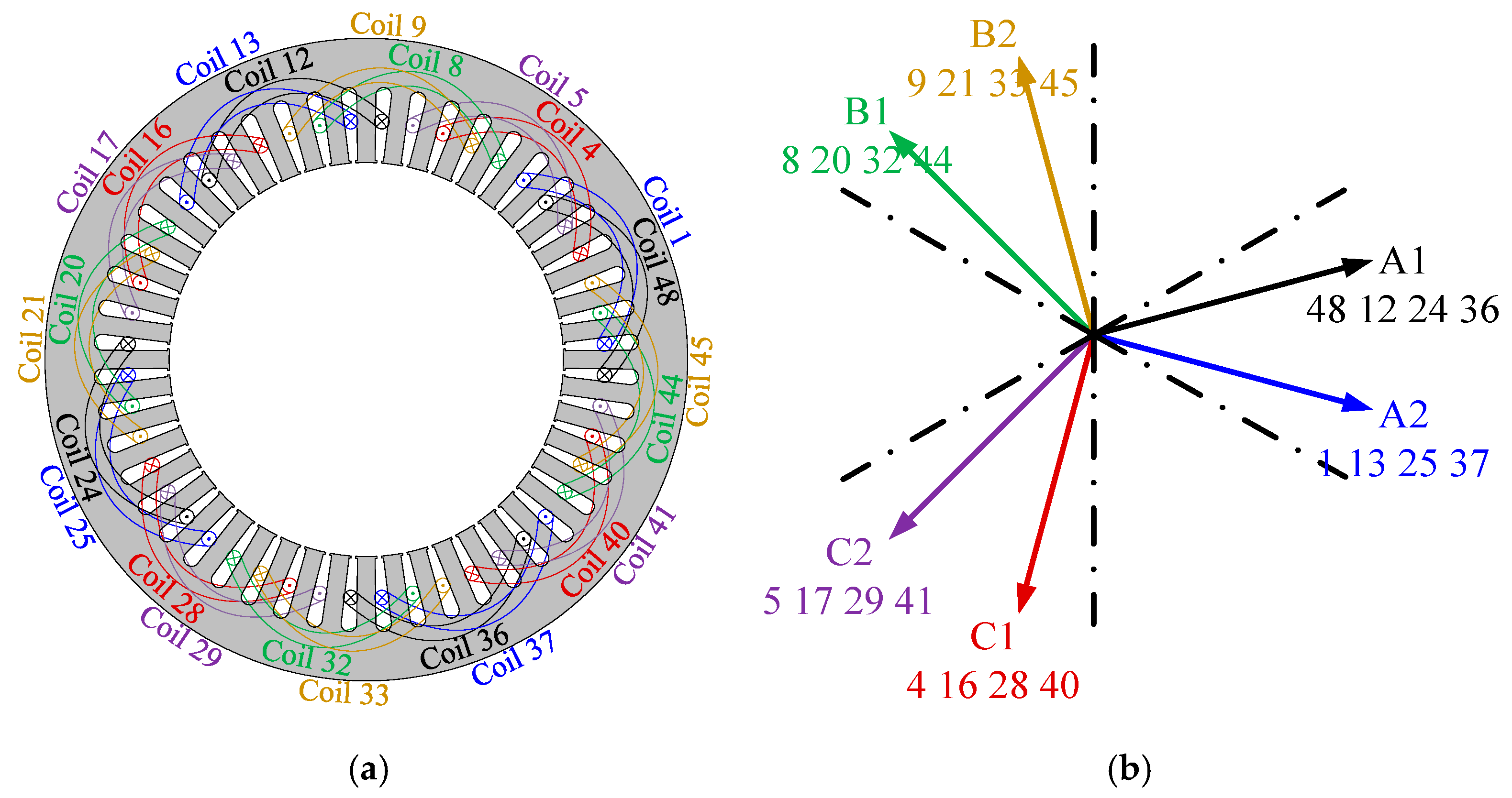
In this section, the electromagnetic performances of the benchmark DTP PMSMs with IPM and AIPM rotors are compared, including comparisons of air-gap flux density, back EMF, cogging torque, torque, loss, and efficiency. It should be mentioned that all the analyses presented below are based on the results obtained from JMAG-Designer by using 2-dimensional (2D) finite element (FE) method.
3.1. Open-Circuit Characteristics
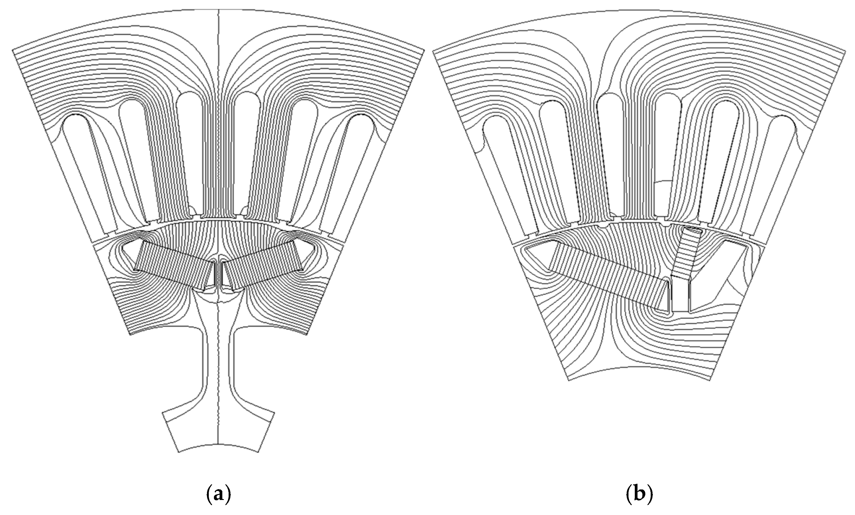
The flux line distributions of the DTP PMSMs with IPM and AIPM rotors under OC conditions are firstly calculated and compared, as shown in
Figure 4. As can be seen, due to the middle-side small magnet and the outside flux barrier in one AIPM rotor pole, closed flux lines can be observed. The waveforms and spectra of the radial flux densities along air-gaps under this condition are shown in
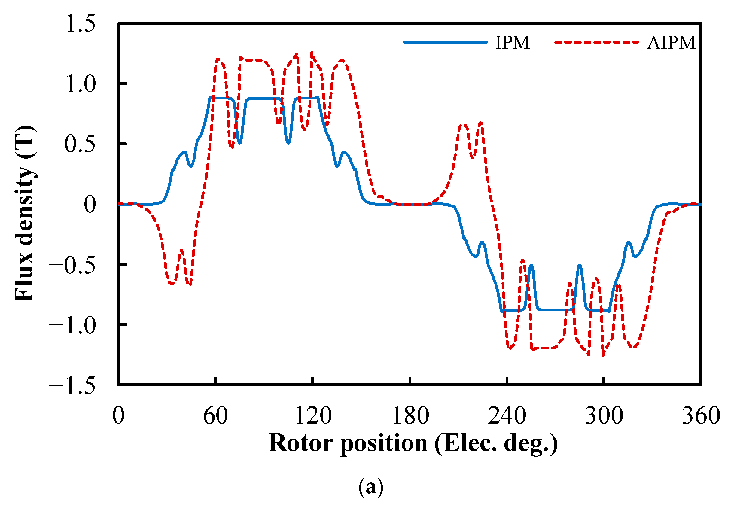
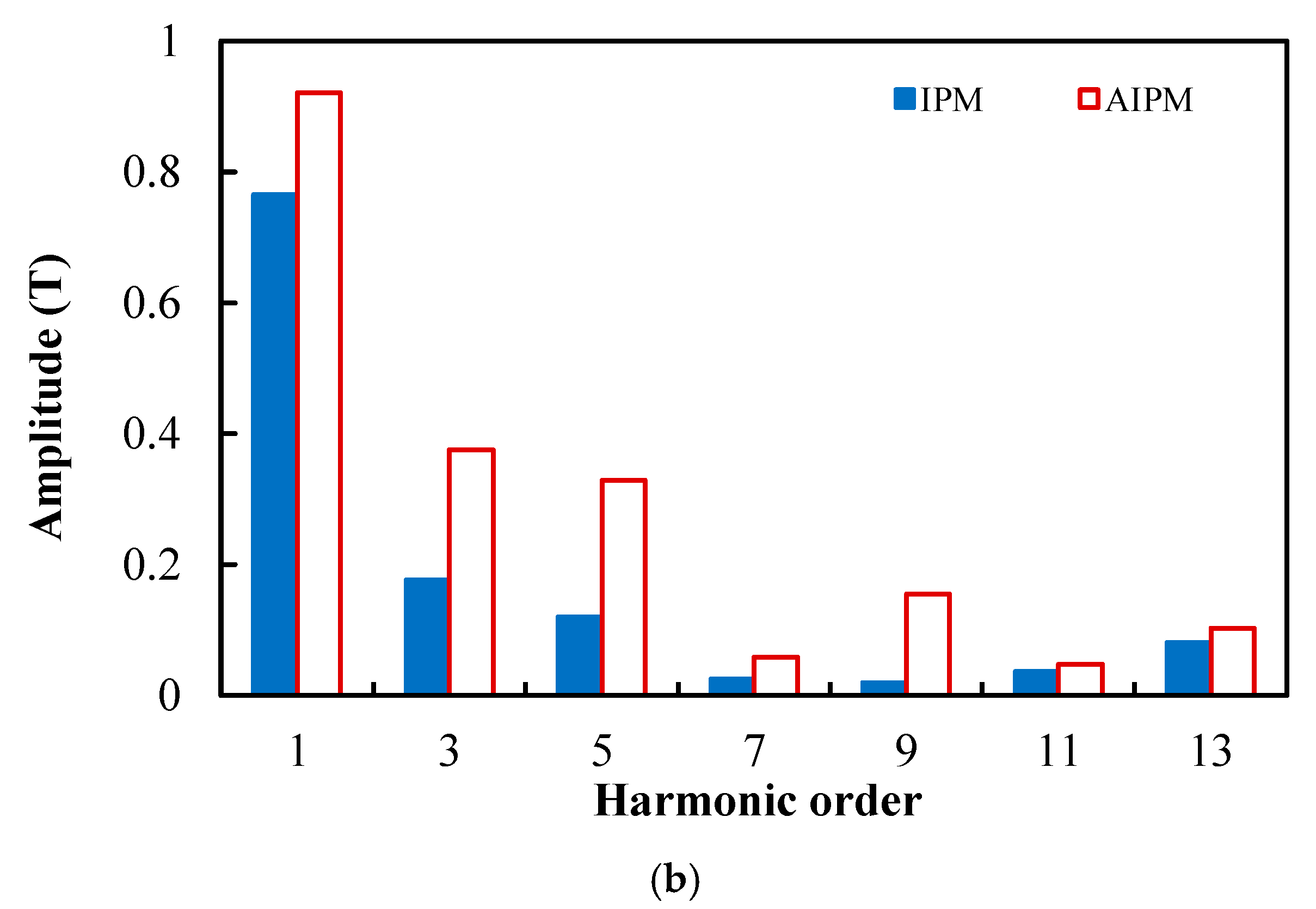
Figure 5a,b. In
Figure 5a, the fluctuations can be explained by the asymmetric rotor layout and the closed flux lines in one AIPM rotor pole. In
Figure 5b, it can be clearly seen that the AIPM rotor has a higher fundamental component, which can be attributed to the flux-focusing effect caused by the flux barrier in the AIPM rotor. However, the AIPM machine also shows more harmonic contents compared with its IPM counterpart, which may result in larger eddy current loss in the AIPM machine. Hence, the flux density distributions of the benchmark PMSMs under OC conditions suggest that the loss and efficiency of the DTP PMSMs with IPM and AIPM rotors need more attention in the following analyses.
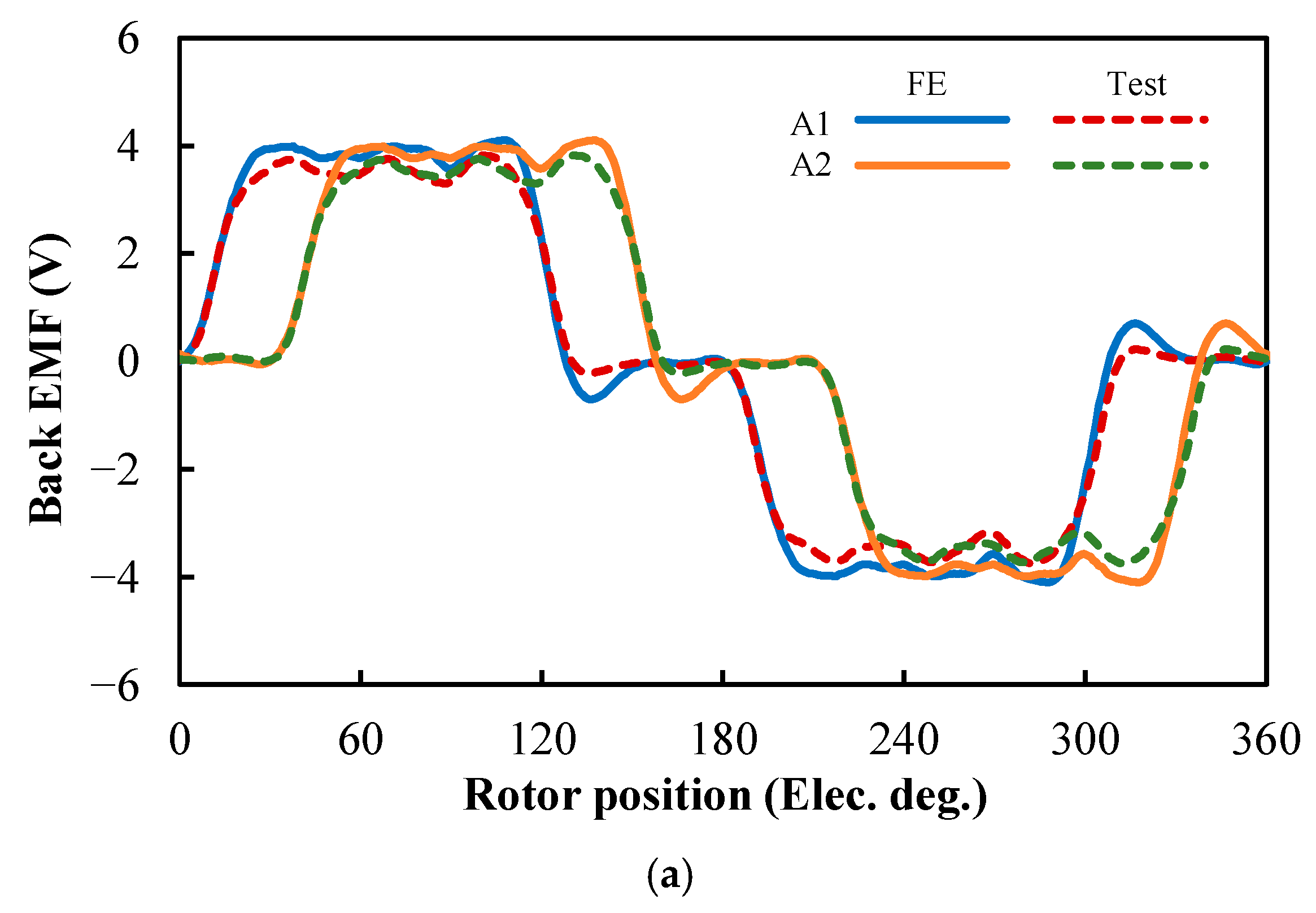
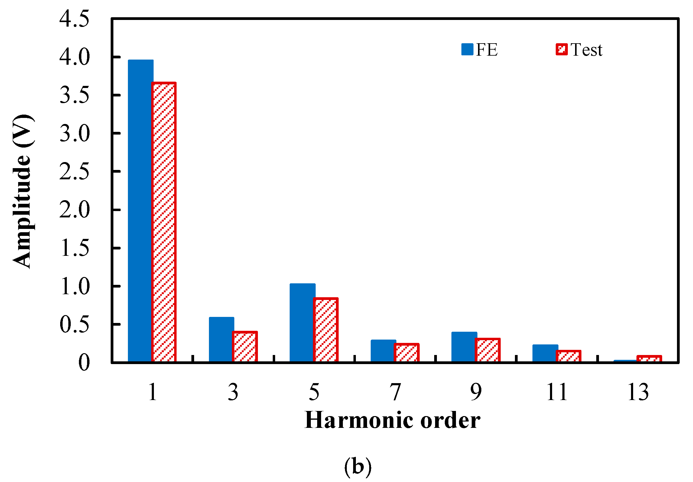
In the DTP PMSMs with IPM and AIPM rotors, assuming rotor speed is 200 rpm, the waveforms and spectra of phase back electromotive forces (EMFs) of Phases A1 and A2 are shown in
Figure 6. In
Figure 6b, it can be seen that similarly to the OC air-gap flux density, the amplitude of the fundamental back EMF in the AIPM machine is higher than that in the IPM machine.
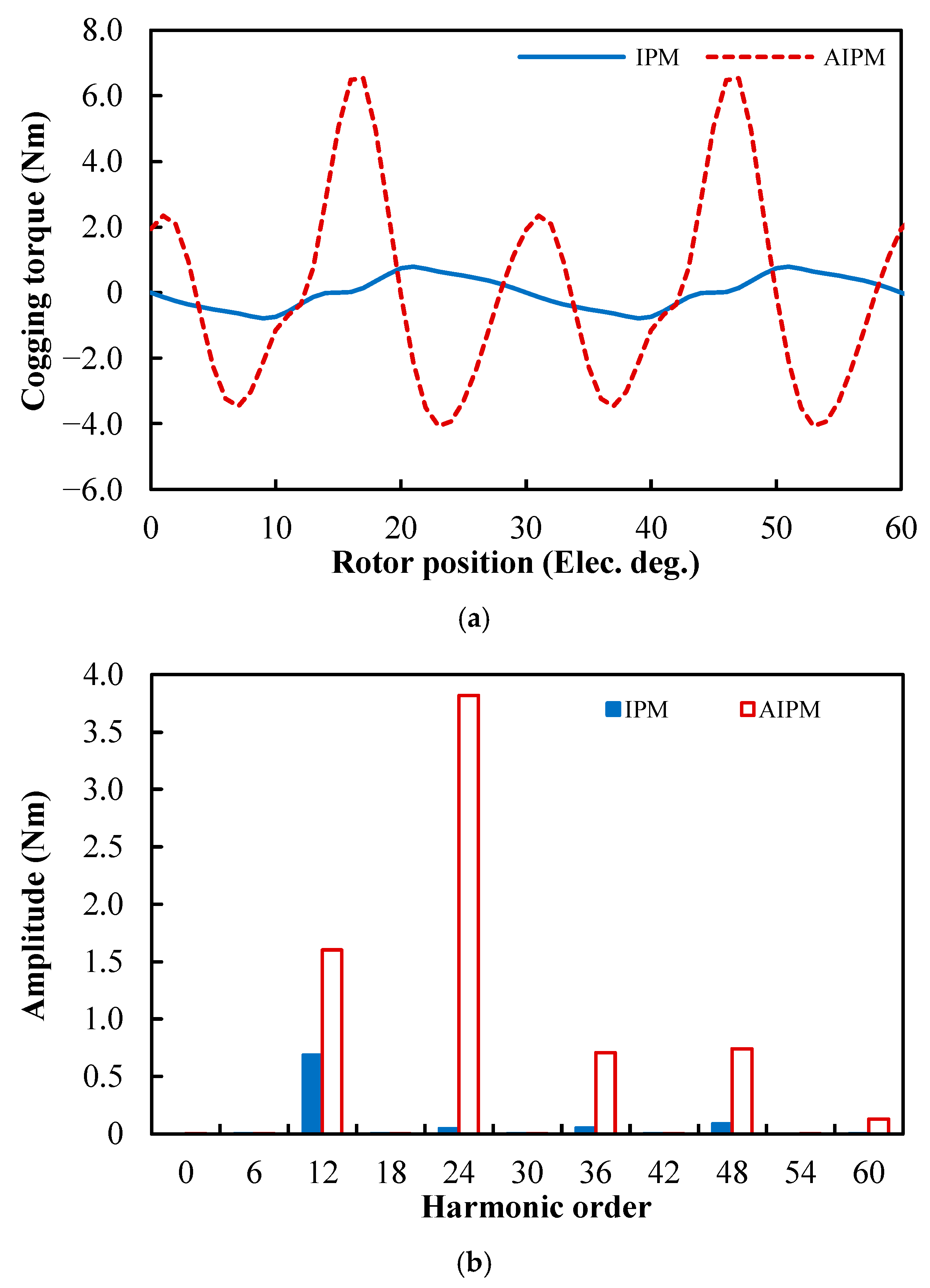
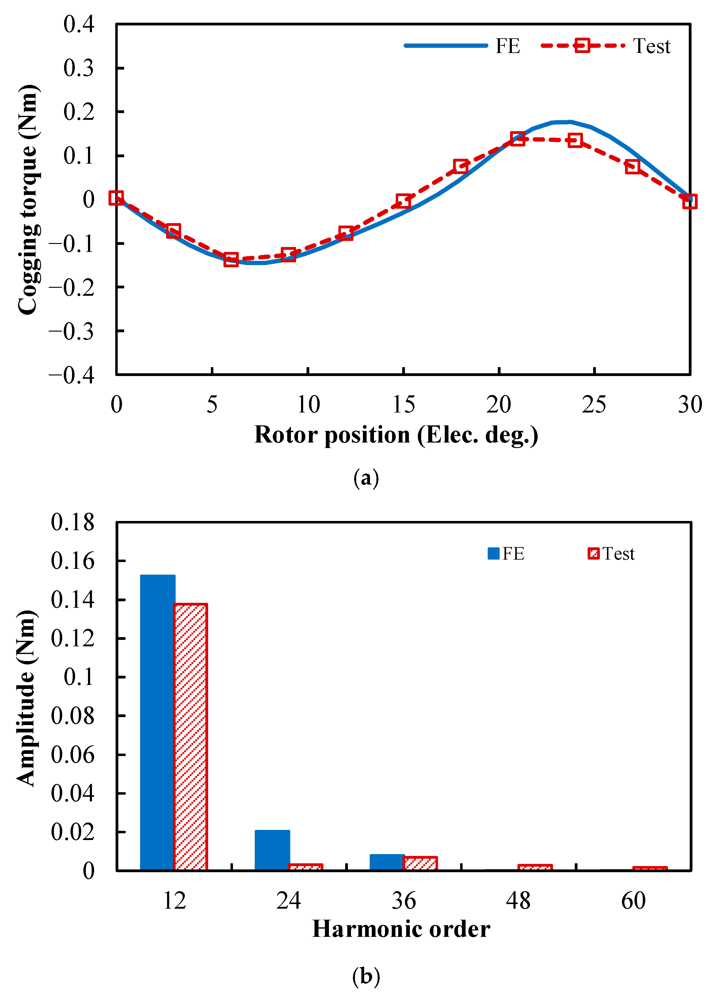
For the DTP PMSMs with IPM and AIPM rotors, the waveforms and spectra of the cogging torques are given in
Figure 7a,b. Due to the same slot/pole number combination, the fundamental orders of cogging torque in the IPM and AIPM machines are exactly the same, which is 48 in mechanical angle (the smallest common multiple between slot number, 48, and pole number, 8) and 12 in electric angle, but the amplitudes of the same harmonic order are different in the IPM and AIPM machines. In the analyzed DTP PMSMs, the cogging torque produced by the AIPM rotor is much larger than that produced by the IPM rotor.
3.2. Torque Characteristics
In this section, the torque characteristics of the DTP PMSMs with IPM and AIPM rotors are first compared under the full load. In the Toyota Prius 2010 machine, the phase current amplitude under the full load is 236 A, and in the benchmark DTP PMSMs, due to different winding configurations, the phase current amplitude for the full load is 118 A. In the DTP PMSMs with IPM and AIPM rotors, the variations in average torque with current advancing angle under the full load (
IA1 = 118 Apk) are shown in
Figure 8. It can be seen that the maximum average torques are obtained when current advancing angle = 53° in the IPM machine, and 62° in the AIPM machine.
As mentioned before, in IPM and AIPM machines, the variations in the PM and reluctance torque components with current advancing angle are quite different. With the help of the frozen permeability method [
35,
36,
37], the PM and reluctance torque components can be separated from the total average torque. The variations in the PM and reluctance torque components with current advancing angle are also presented in
Figure 8. It can be found that the optimal current advancing angles for the maximum PM torque component are 24° in the IPM machine, and 53° in the AIPM machine. To achieve the maximum reluctance torque component, the optimal current advancing angles are 58° and 65°, respectively, in IPM and AIPM machines. The current advancing angles to achieve the maximum total, PM, and reluctance torques in the IPM machine were marked with dash lines in the figure. Similarly, the current advancing angles to obtain the maximum total, PM, and reluctance torques in the AIPM machine were marked with dot-dash lines in Figure 20. The optimal current advancing angles for different torque components are summarized in
Table 2. In the IPM machine, the difference between the optimal current advancing angles for the maximum PM and reluctance torque components is 34°, but in the AIPM machine, the difference is only 12°. It can be concluded that compared with the IPM rotor, the PM and reluctance torque components in the DTP PMSMs can be better utilized by using the AIPM rotor.
In
Figure 8 and
Table 2, it can be seen that, under the full load (
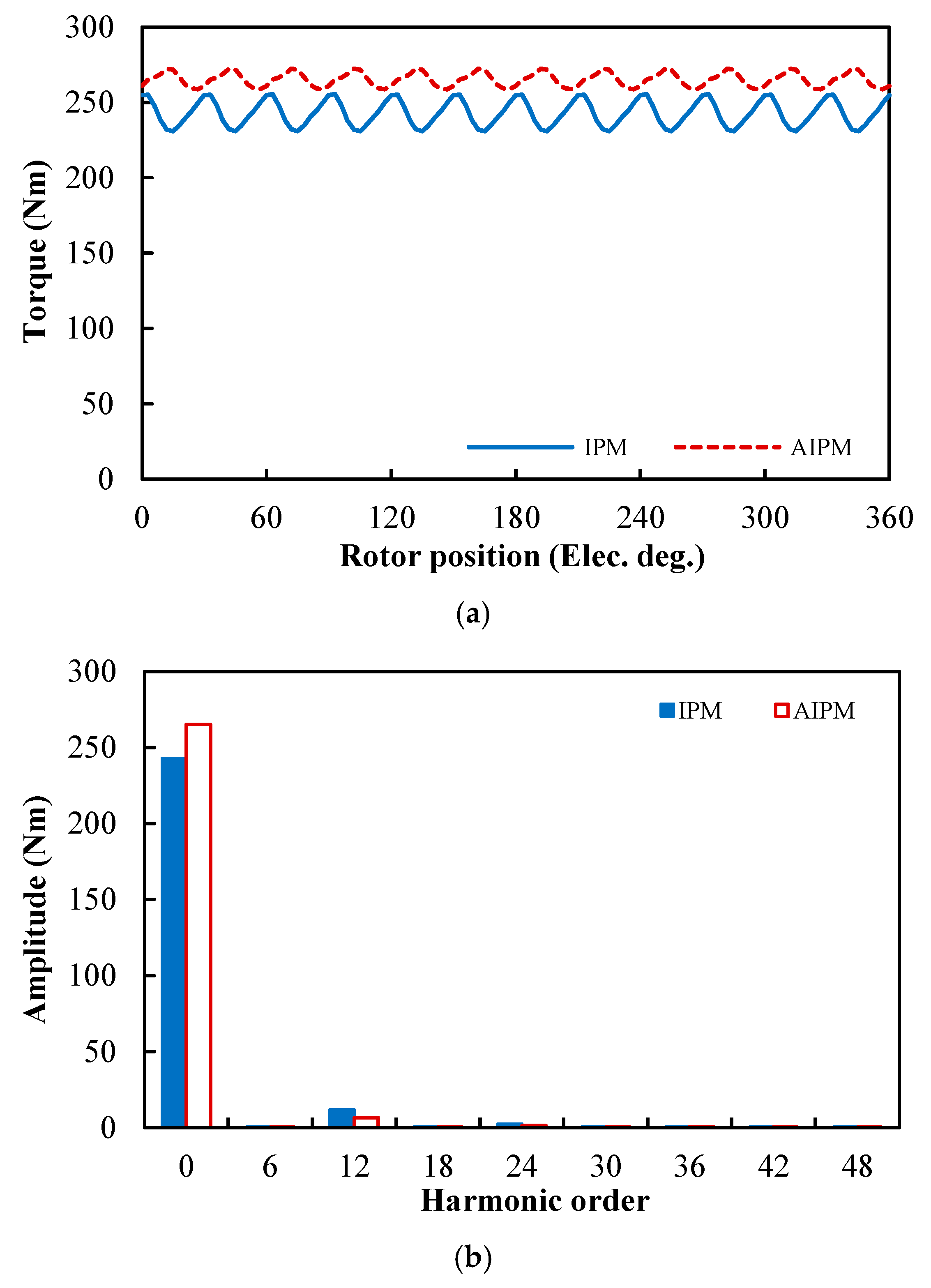
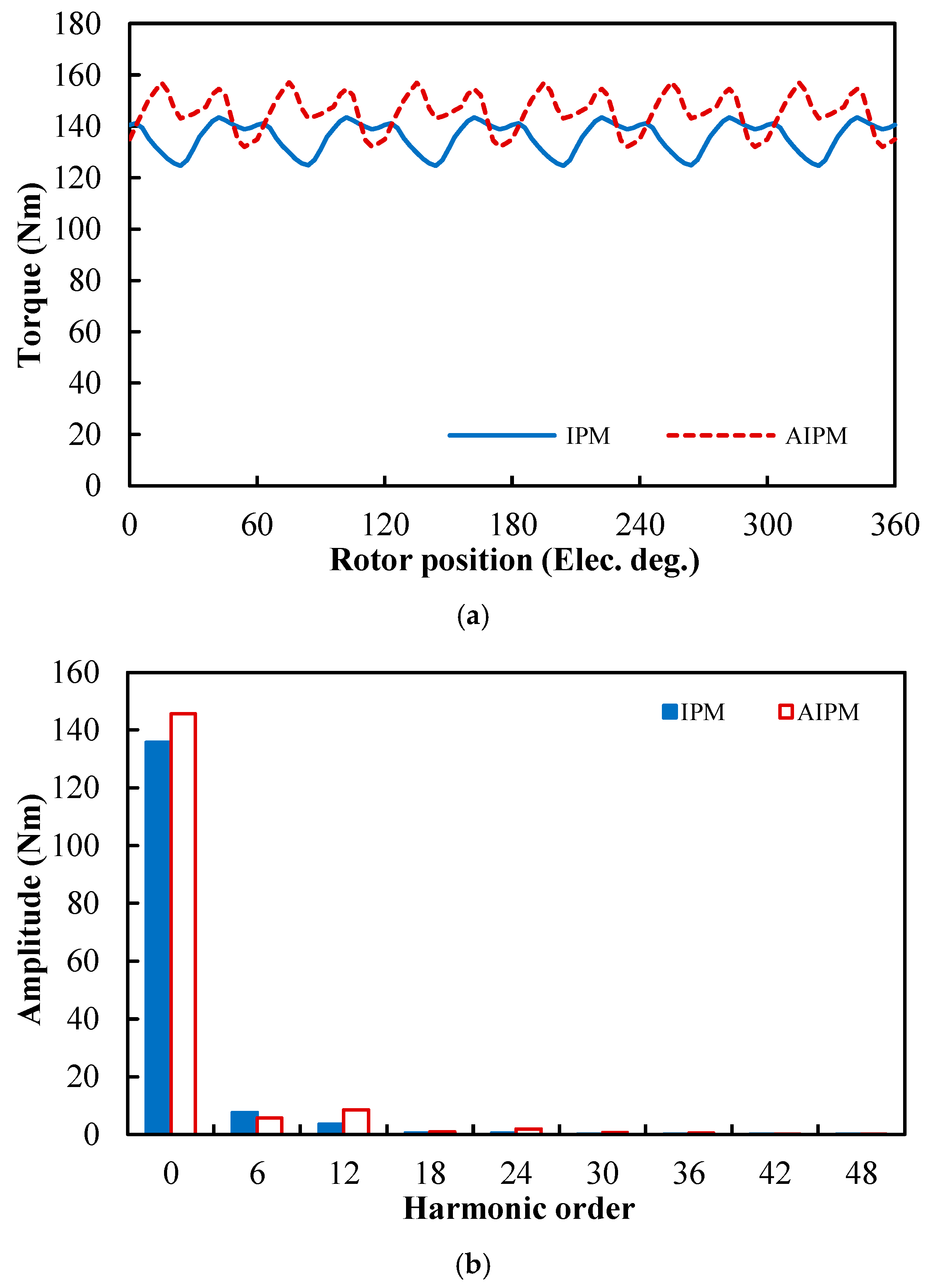
IA1 = 118 Apk), to achieve the maximum average torque, the optimal current advancing angles are 53° and 62°, respectively, in IPM and AIPM machines. With the optimal current advancing angles, the waveforms and spectra of the instantaneous torque in the DTP PMSMs with IPM and AIPM rotors are shown in
Figure 9. The average torque and torque ripple characteristics of the PMSMs under the full load are summarized in
Table 3. It can be seen that compared with the DTP IPM machine, the DTP AIPM machine can increase the average torque by 9.25% and reduce the torque ripple by 47.62% under the full load.
The prototype DTP PMSMs in this paper are modified from the STP PMSMs in [
30], by changing the winding configurations and optimizing the rotor design. With the STP windings, the torque characteristics of the STP PMSMs under the full load are provided in
Table 4. The results for DTP and STP PMSMs can be compared. Under the full load, the STP AIPM machine can increase the average torque by 8.35% and reduce the torque ripple by 34.08% compared with the STP IPM machine. Hence, by employing the AIPM rotor, DTP PMSM can achieve greater improvements in the average torque and reductions in torque ripple than those in STP PMSM, which may be due to the more severe magnetic saturation in the DTP PMSM.
Under other load conditions, the optimal current advancing angles can also be obtained based on the maximum torque per amplitude (MTPA) control strategy. In the DTP IPM and AIPM machines, assuming
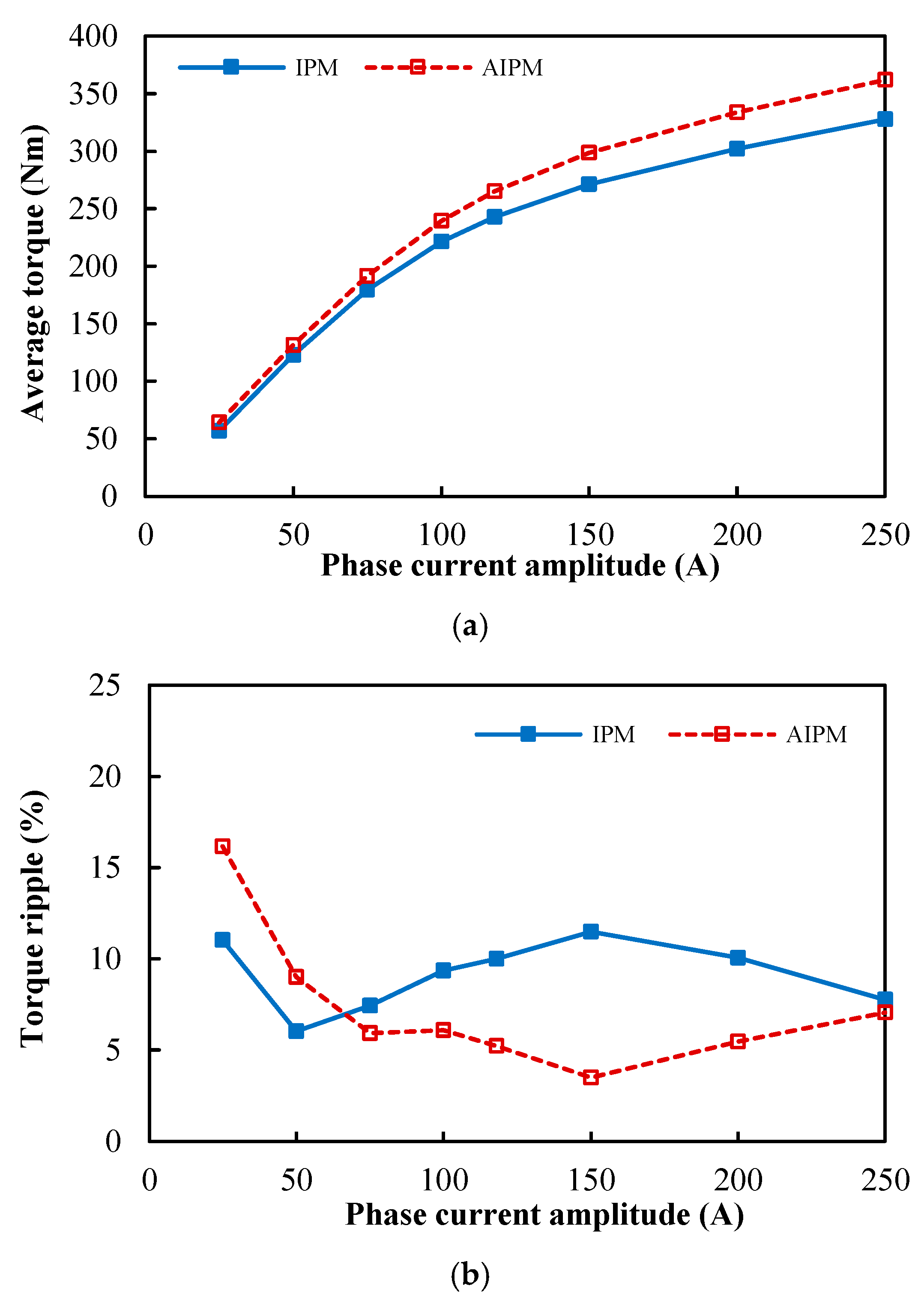
IA1 varies from 25 Apk to 250 Apk to cover the load conditions from light-load to over-load, the variations in average torques and torque ripples with phase current amplitude are shown in
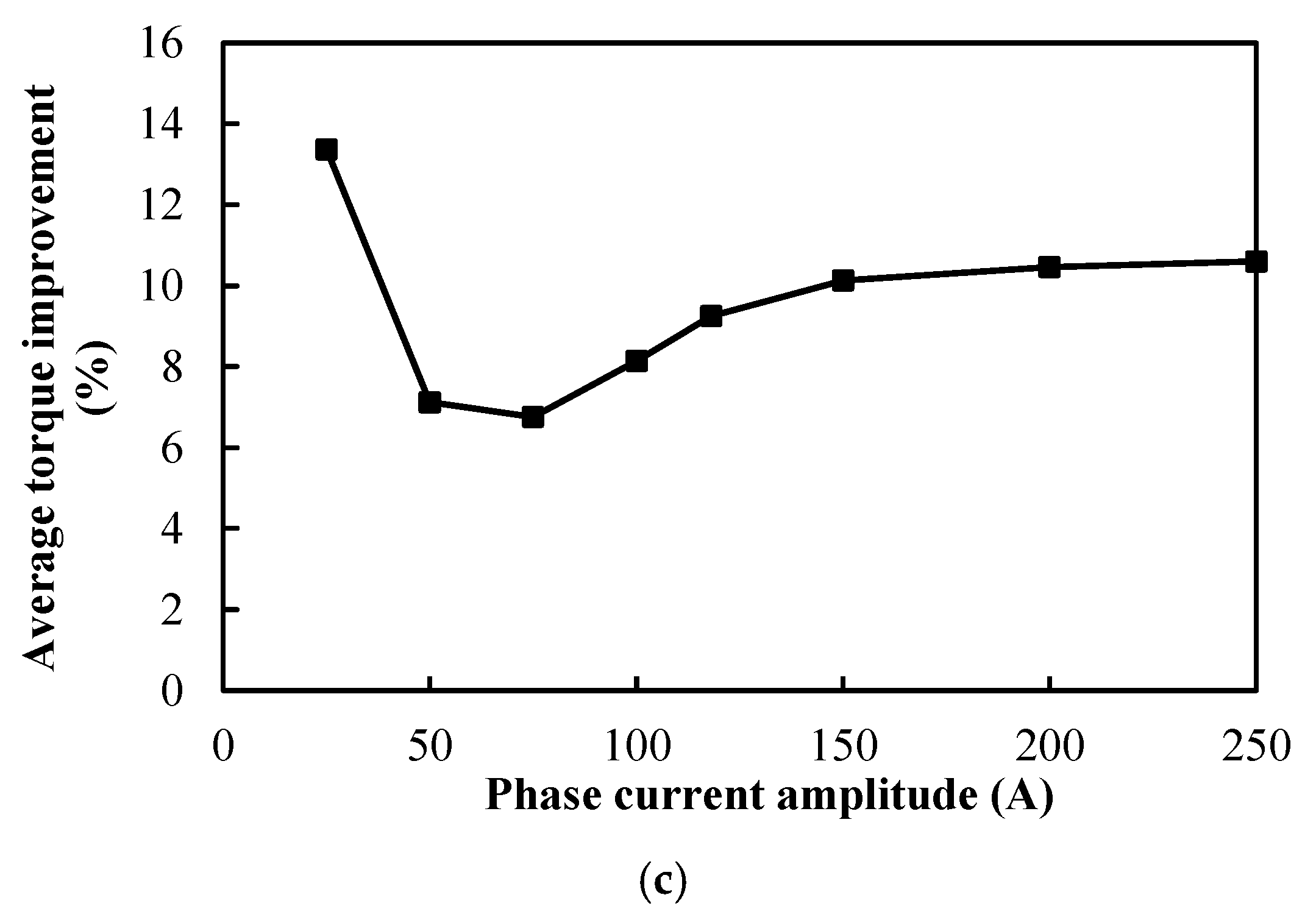
Figure 10a,b, respectively. It can be seen that the average torque of the DTP PMSM can always be improved significantly by using the AIPM rotor, and the average torque improvements are presented in
Figure 10c. In addition, when the phase current ≥ 75 Apk, not only can the average torque be improved, but the torque ripple can also be reduced using the AIPM rotor. Hence, the AIPM rotor can greatly improve the torque performance of the DTP PMSM.
3.3. Loss and Efficiency
In this paper, the losses and efficiencies of the DTP PMSMs with IPM and AIPM rotors are obtained by using the method in [
38]. The copper loss is calculated, using Joule’s law, as follows:
where
R0 is the phase resistance of the DTP windings, and
Ia is the phase current amplitude.
The calculation of iron losses consists of hysteresis and eddy current iron losses, which are calculated using the following:
where
PHyst-base and
PEddy-base are the hysteresis and eddy current iron losses at the base speed, i.e., 3000 rpm in this study, and
f and
fbase are the frequencies of the operating condition and the base speed, respectively.
PM eddy current losses are obtained from FE simulations directly, and mechanical losses are estimated by [
39].
Overall, the loss characteristics of the DTP PMSMs with IPM and AIPM rotors under the full load (
IA1 = 118 Apk, speed = 3000 rpm) are summarized and compared in
Table 5.
It can be found that the total losses in IPM and AIPM machines are 7.81 kW and 7.82 kW, respectively. In other words, the asymmetric IPM rotor could only slightly affect total losses. It can be further inferred that the temperature performance of the DTP PMSMs with IPM and AIPM rotors will not show evident differences, as presented in the STP counterparts [
30].
It can be seen that copper loss is the most dominant loss in both the IPM and AIPM machines. Since the IPM and AIPM machines share the same stator and armature windings, the copper losses of the two DTP PMSMs are identical. Due to similar iron loss and higher PM eddy current loss, the total loss in the AIPM machine is slightly higher than that in its IPM counterpart. However, considering that the output torque and output power of the AIPM machine are obviously larger than those of the IPM counterpart, the AIPM machine still has higher overall efficiency than the IPM counterpart under this condition.
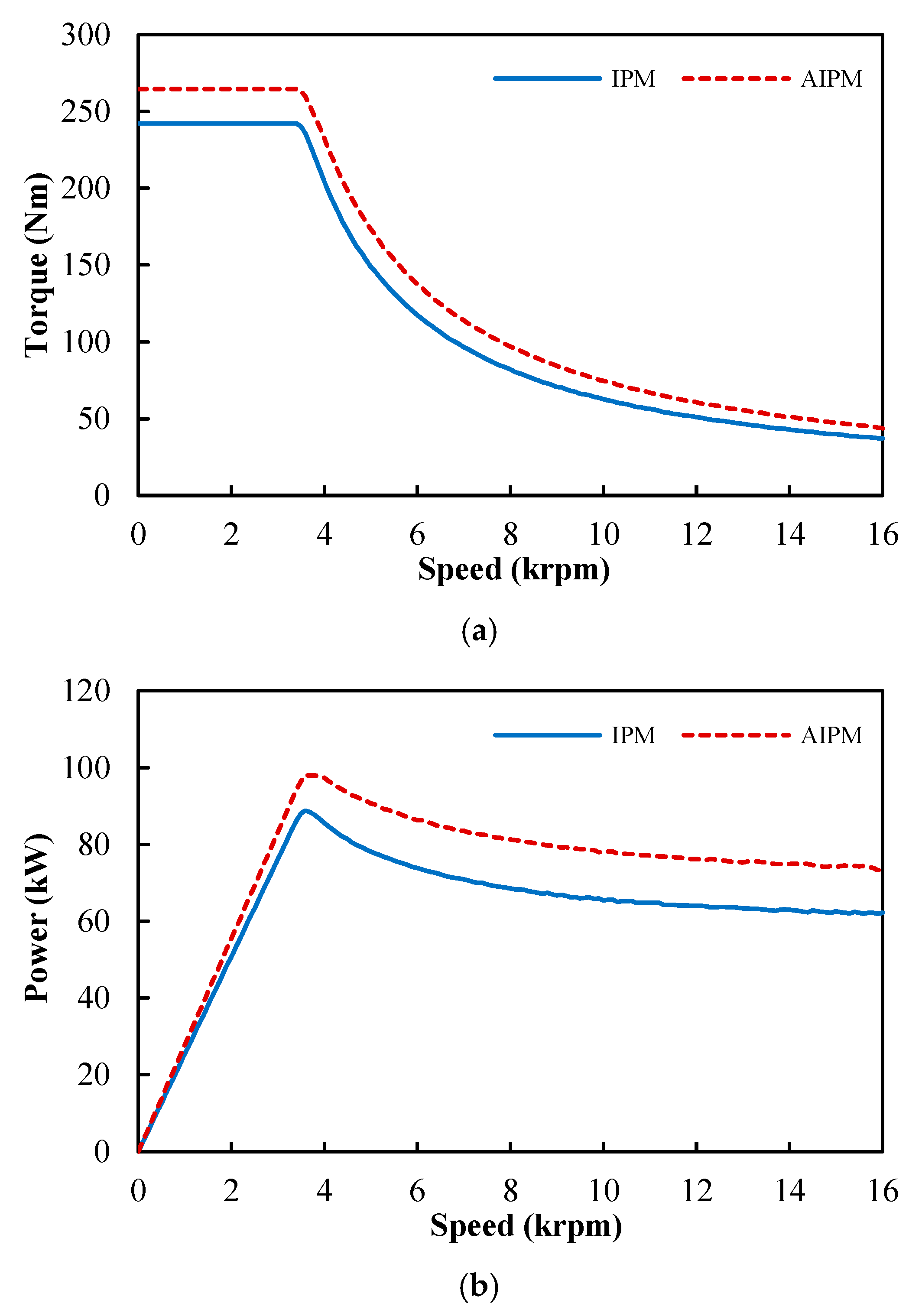
To analyze the loss and efficiency characteristics of the DTP PMSMs with IPM and AIPM rotors at other speeds, the torque and power–speed curves of the two DTP PMSMs are calculated under the constraints.
To analyze the loss and efficiency characteristics of the DTP PMSMs with IPM and AIPM rotors at other speeds, the torque and power–speed curves of the two DTP PMSMs are calculated under the constraints (DC link voltage ≤ 650 Vdc and phase current ≤ 118 Apk), as shown in
Figure 11. Similarly, the variations in the maximum d- and q-axis currents (I
d and I
q), and phase currents (I
a) with speed are shown in
Figure 12. It can be clearly seen that the AIPM machine can produce higher torque than the IPM counterpart, not only in constant torque region (low speed), but also in constant power region (high speed).
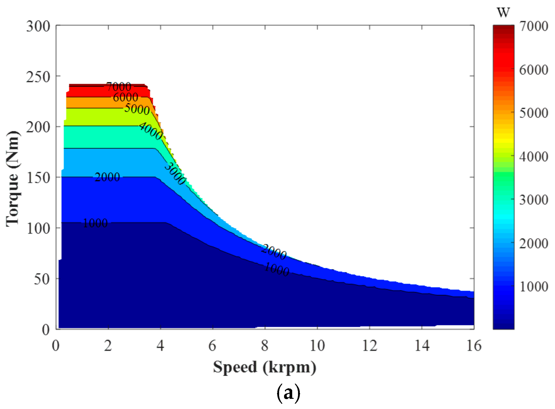
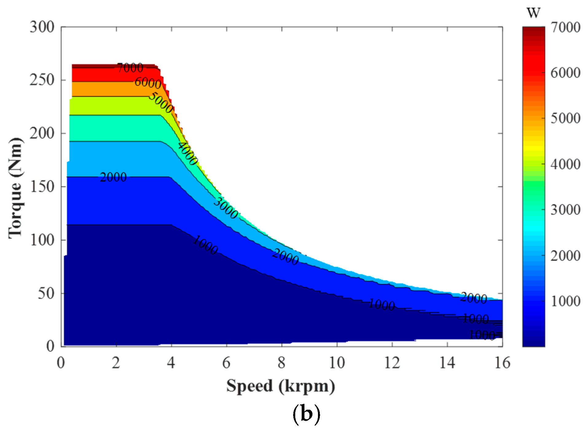
Based on (1), (2), and
Figure 11 and
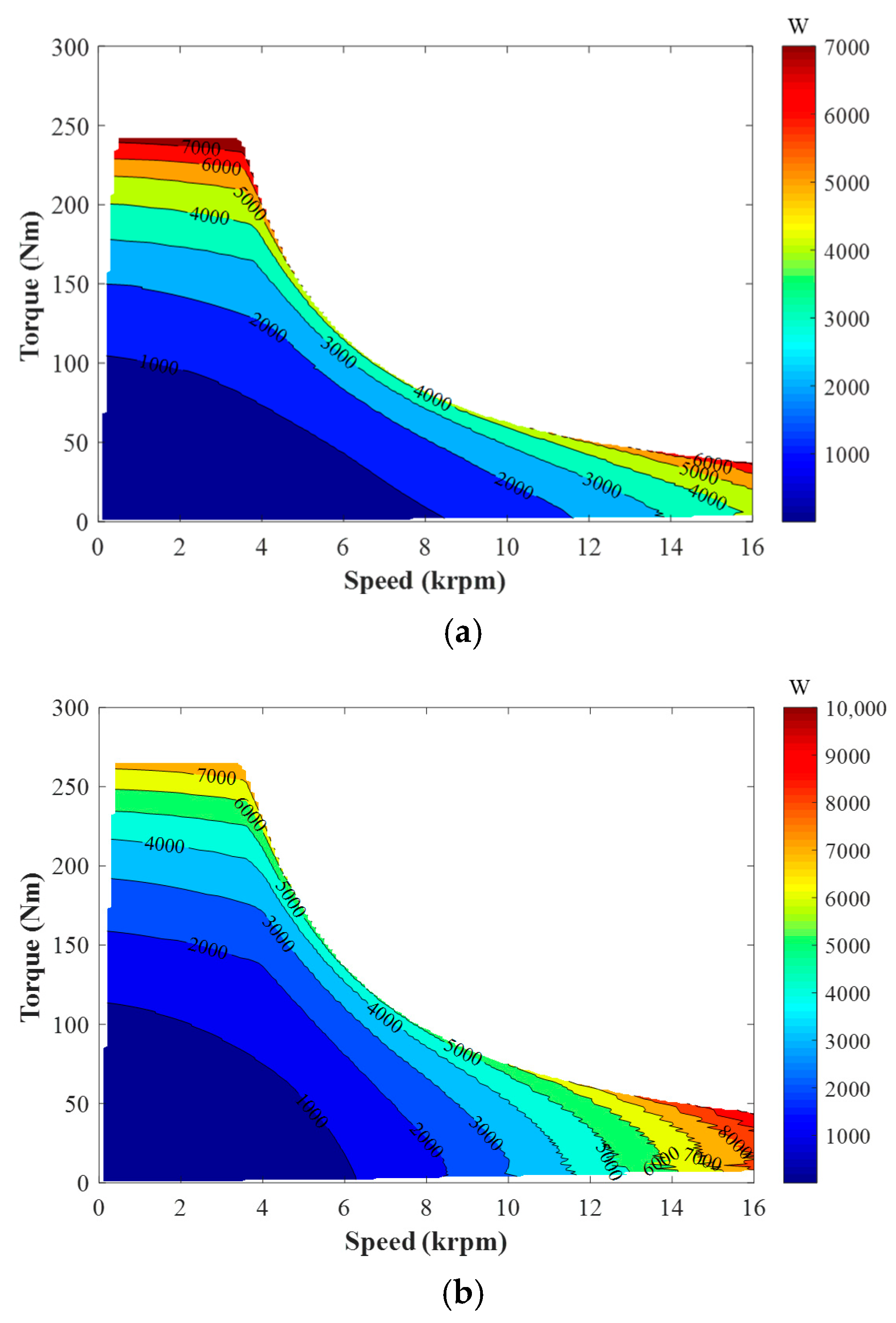
Figure 12, the copper loss and iron loss maps of the DTP PMSMs with IPM and AIPM rotors are calculated, as shown in
Figure 13 and
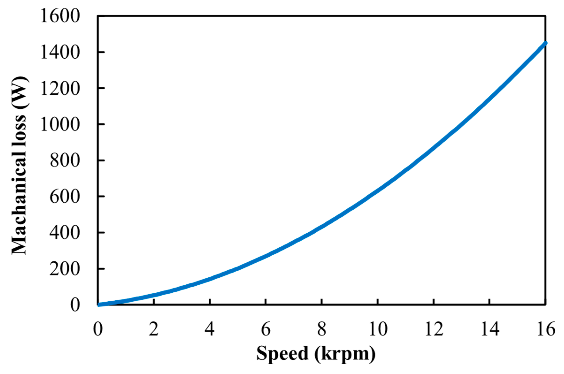
Figure 14, respectively. The mechanical losses of the DTP IPM and AIPM machines are calculated by using (3), as shown in
Figure 15.
Considering that the PM eddy current loss under other speeds cannot be estimated directly from the base speed, and that the PM eddy current loss is very small in total loss, as indicated in
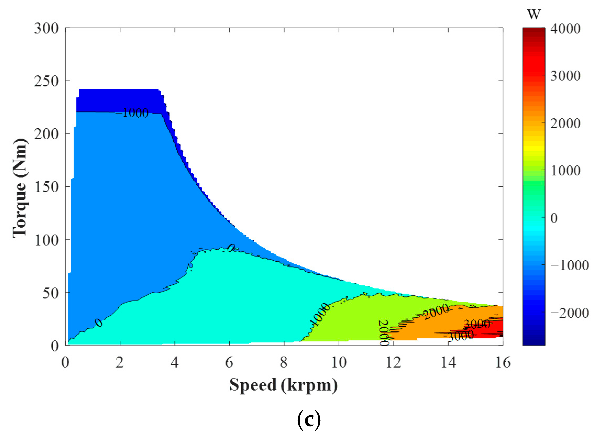
Table 5, the disregard of PM eddy current loss in the calculation of resultant efficiency is still acceptable. Thus, when ignoring PM eddy current loss, the total loss maps of the DTP IPM and AIPM machines can be obtained from
Figure 13,
Figure 14 and
Figure 15, as shown in
Figure 16. The total loss difference between the AIPM and IPM machines is given in
Figure 16c. In
Figure 16c, the operating conditions can be classified into three conditions: low-speed and low-torque, low-speed and high-torque, and high-speed conditions. It can be observed that at high speed, iron loss is the dominant loss and the AIPM machine has higher total loss, while at low speed and high torque, copper loss is the dominant loss and the IPM machine has higher total loss. At low speed and low torque, the AIPM and IPM machines show similar total losses.
In
Figure 14, it can be observed that the iron loss in the AIPM machine is higher than that in the IPM counterpart at high speed, and at low speed and low torque. However, as shown in
Table 5, the iron loss of the AIPM machine is slightly lower than that of the IPM counterpart at the full load (low speed and high torque). Considering that the phase currents under different operating conditions are different, it is necessary to further analyze the effects of electric loading on iron losses in the DTP AIPM and IPM machines.
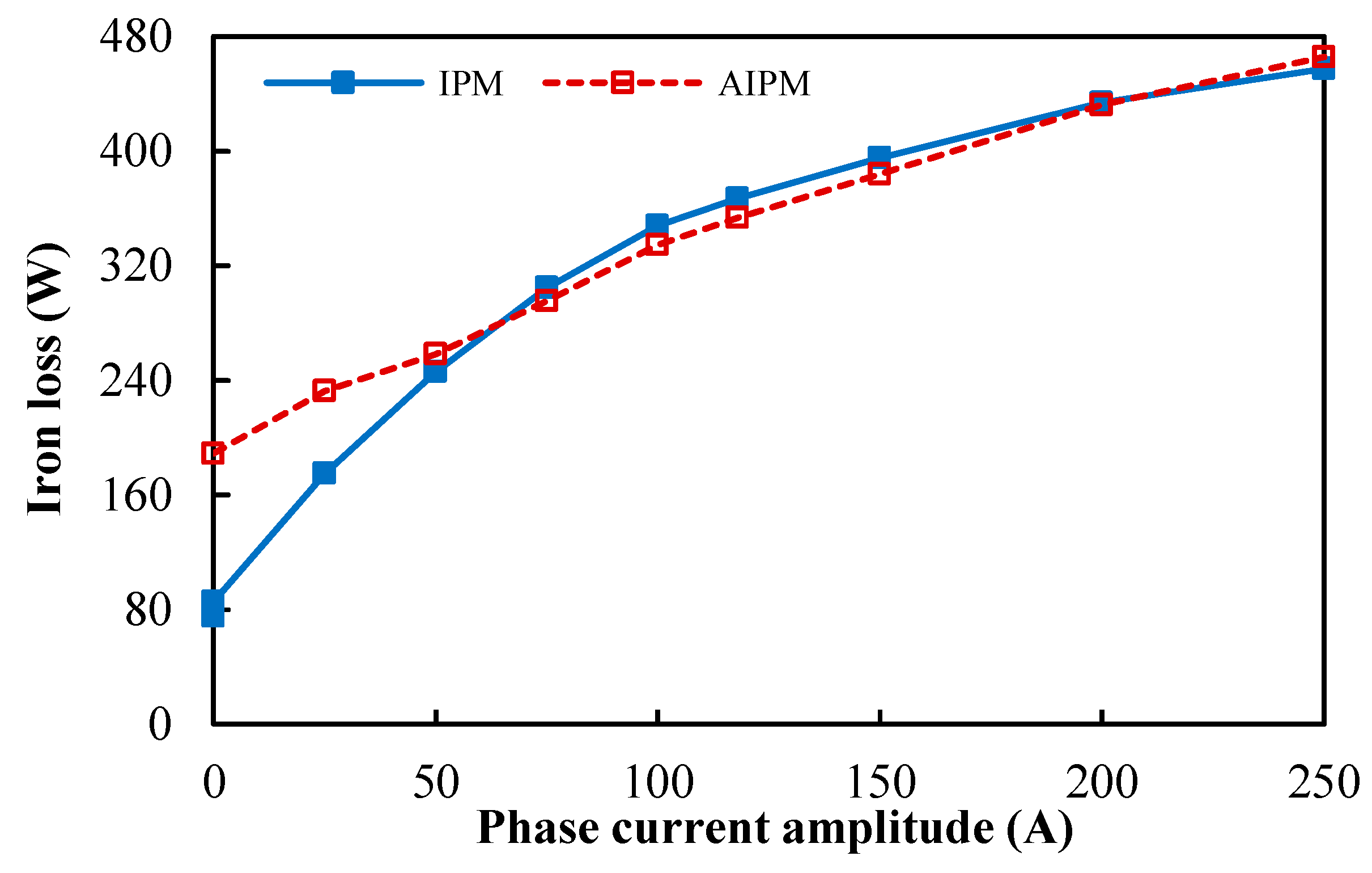
Assuming the phase currents vary from 0 to 250 Apk, the iron losses of the DTP PMSMs with the IPM and AIPM rotors at 3000 rpm are compared in
Figure 17. It can be observed that the iron loss in the DTP AIPM machine is higher than that in the IPM counterpart at low currents (≤50 Apk), but lower than that in the IPM counterpart at high loads (≥75 Apk). This phenomenon can be explained by the different air-gap MMF harmonic contents in the AIPM and IPM machines. When electric loading is low, the air-gap MMF is mainly produced by rotor PMs. Under open-circuit conditions, the air-gap flux densities of the DTP AIPM and IPM machines are shown in
Figure 5. In
Figure 5b, it can be seen that the AIPM machine has a higher fundamental component (0.77 T in the IPM machine, and 0.92 T in the AIPM machine) and more abundant harmonic contents (THD = 42.66% in the IPM machine, 68.42% in the AIPM machine). Hence, the iron loss of the DTP AIPM machine is significantly higher than that in the DTP IPM machine under low-load conditions. However, with the increase in phase currents, the air-gap flux densities of the DTP AIPM and IPM machines are mainly affected by armature windings, and less affected by rotor PMs. Under the full-load conditions (
IA1 = 118 Apk), the air-gap flux densities of the DTP AIPM and IPM machines are compared in
Figure 18.
It can be seen that the air-gap flux densities of the DTP IPM and AIPM machines are close to each other under this condition. In addition, due to the different rotor layouts, the harmonic contents in the AIPM machine are even lower than those in the IPM counterpart under this condition (THD = 41.57% in the IPM machine, 38.44% in the AIPM machine). As a result, compared with the DTP IPM machine, the DTP AIPM machine shows higher iron loss when electric loading is low (under low-speed and low-torque, and high-speed conditions) and lower iron loss when electric loading is high (at low speed and high torque).
Based on
Figure 16, the efficiency maps of the DTP PMSMs with IPM and AIPM rotors are calculated, as shown in
Figure 19a,b, respectively. The efficiency difference between the AIPM and IPM machines is presented in
Figure 19c.
It can be found that the DTP AIPM and IPM machines show higher efficiencies under different operating conditions. Due to the more abundant PM MMF harmonics in the DTP AIPM machine, the DTP AIPM machine shows a higher iron loss and lower efficiency than the IPM counterpart at high speed. However, when electric loading is higher, the iron losses due to armature reaction field become more significant and hence the iron losses in IPM and AIPM machines become more similar to each other. Thus, the investigated DTP AIPM topology exhibits higher efficiency than the IPM counterpart at high-torque and high-load conditions, due to the optimization goal only focusing on higher torque density [
39].
