1. Introduction
Thermoelectric generators (TEGs) have attracted increasing interest in recent years, which calls for more improved and efficient modeling techniques. The two most common approaches are the detailed physical simulations and simplified equivalent-circuit models. Detailed three-dimensional finite element models can account for complex geometries with high accuracy and include all physical phenomena such as the Seebeck, Peltier, Joule, and Thomson effects [
1,
2,
3,
4,
5,
6].
For example, Luo et al. [
1] provide a broad review of theoretical TEG models, covering one-dimensional analytical formulas, finite element method (FEM) simulations, and circuit analogies and offer a detailed comparison between FEM and 1D models.
Korotkov et al. [
2] demonstrate techniques for modeling TEGs using FEM with the ANSYS Workbench software.
Bjørk et al. (2014) [
3] use a 3D numerical TEG model to investigate internal heat-loss mechanisms—conduction through the module materials, natural convection inside the module, and radiation—finding that radiative and conductive losses have comparable impacts on a TEG performance.
Verification of FEM techniques against experiments is also presented by Seetawan et al. [
4]. Chen et al. (2025) [
5] experimentally validated the conclusions of a classic 1D TEG model, importantly confirming that maximum output power occurs at an optimal load resistance—the true optimum includes not only the TEG’s internal resistance but also contact and wiring resistances.
Sajjad et al. [
6] present a comprehensive review of machine learning methods for predicting and optimizing TEG performance, summarizing how regression techniques, deep neural networks, and physics-informed machine learning models are used for TEG modeling and design optimization, and pointing out challenges such as limited datasets and the need for experimental validation. They suggest that integrating machine learning with traditional simulations could accelerate the development of high-performance TEGs.
FEM-based simulations, while accurate, are computationally intensive and not suitable for rapid design iterations. Electronics engineers often find these tools impractical for obtaining quick simulation results, especially when a TEG must be co-simulated with an electronic circuit under varying loads and temperatures.
To enable faster analysis, researchers have developed electrothermal TEG models compatible with circuit simulators [
7,
8,
9,
10,
11]. Early works focused on thermoelectric coolers, representing them as equivalent circuits in software tools like PSPICE. These models use analogies between thermal and electrical quantities and run in circuit simulation environments.
Adapting such models for power generation requires adding a voltage source element to represent the Seebeck effect (the open-circuit voltage generated by a temperature difference). In recent years, these models have been refined by incorporating temperature-dependent material parameters and more accurate representations of heat flow [
7,
8,
9,
10,
11].
Dziurdzia et al. [
12] introduced an electrothermal TEG model based on the LTspice that captures coupled thermoelectric behaviors while remaining efficient in circuit-level simulation. The model links the ambient, hot-side, and cold-side temperatures to the TEG’s output power, accounting for the low internal resistance of TEG modules and the nonlinear, temperature-dependent performance of thermoelectric materials. This approach allows co-simulation of the TEG with power management circuits, making it possible to simulate complete energy-harvesting systems. Circuit simulator-based TEG modeling enables designers to optimize TEGs for different applications (such as in IoT sensors, automotive systems, and wearable electronics) before hardware implementation.
Thermoelectric energy harvesting is a promising approach for recovering “free” waste heat in many applications, from domestic and industrial heat sources to wearable devices. The basic configuration uses a thermoelectric module attached to the hot surface of a heat source and a heatsink on the other side. The heatsink is essential for cooling the cold side by dissipating heat to the environment, and its effectiveness largely determines the sustained temperature gradient. In practice, the heatsink is often physically much larger than the TEG module itself and it complicates the miniaturization of TEG systems. When a temperature difference ΔT is present, the module produces a Seebeck voltage in open circuit and generates electrical energy when a resistive load is connected. This property of TEGs is used for waste-heat recovery in many scenarios, and numerous researchers have been studying various case studies. The latest results in waste-heat recovery using TEGs can be found in [
13].
Hooshmand Zaferani et al. (2021) [
14] reviewed the application of thermoelectric modules for waste-heat recovery across different industries and use-cases. They present systems in industrial processes (e.g., cement kilns) and low-temperature environments such as human body heat, and highlight the importance of temperature management. In low-temperature heat sources like wearables, the design must cope with a very small temperature gradient ΔT, whereas higher-temperature systems require durable materials and often include heat exchangers or heatsinks for cooling. In [
15,
16] the authors presented interesting methods of sensor calibration for building thermal systems.
Dizaji et al. (2024) proposed an improved TEG design for industrial waste-heat recovery [
17], employing a passive (energy-free) cooling technique on the cold side. In their configuration, one side of the TEG is connected to a hot exhaust stream while the other side is cooled passively (with no external power). This approach greatly increases the output power from the waste-heat source while avoiding the parasitic power draw associated with active cooling.
The development of thermoelectric energy harvesters has been recently enhanced by a significant progress in materials science that has brought new alloys with considerable figures of merit ZT, much higher than 1 [
18,
19,
20,
21]. Recent advances bring new very attractive solutions with potential for harvesting applications, like metamaterials [
22], nanoparticles [
23], near-zero-index materials [
24], graphene [
25], plasmonics [
26], and multifunctional composites [
27].
Tabaie et al. (2023) reviewed recent advances in wearable TEG systems that harvest human body heat [
28]. They noted that matching thermal resistances is crucial due to the small skin temperature differences, and that contact with the skin adds thermal resistance. The key design factors include matching the module’s internal resistance to the external resistance (from the skin and ambient air), optimizing the module’s geometry and flexibility, and accounting for human factors such as changes in skin temperature and perspiration.
Overall, research on wearable TEG systems focuses on improving power density through better heat dissipation, adding insulation when necessary, and using ergonomic heatsink designs (often thin or textile-based) to maintain a useful temperature gradient. In all these studies, a common conclusion is that thermal management at the cold side is often the limiting factor. A high-performance or actively cooled heatsink significantly increases the output power by maintaining a larger temperature difference. It turns out that even in a wearable device with a limited ΔT, adding a small heatsink yields a significant improvement in performance [
29].
Thermoelectric generators (TEGs) systems that utilize waste heat almost always incorporate a heatsink to remove heat from the cold side of the module. Heat sink sizes can range from passive fins and aluminum blocks to active cooling (fans or liquid loops) in larger systems. Designing the optimal heatsink for a given environment is as important as the thermoelectric module itself, because it represents a compromise between maximizing power output and the compact size of the harvesting system.
An innovative strategy for obtaining energy without a traditional heatsink is the concept of pulsed (intermittent) operation for thermoelectric modules [
30]. In 2020, Haras et al. proposed that instead of keeping the TEG constantly connected to a heat source (which leads to thermal equilibrium), the TEG should be periodically disconnected or switched between the heat source and the environment. By cyclically switching the thermal connection on and off, the TEG can periodically cool down, preventing its full thermalization. The thermalization effect (warming up the TEG cold-side temperature) is an adverse process of equalizing temperatures on both sides of the TEM when thermal resistance to the ambient temperature is too high, and it can be mitigated by a pulse mode operation.
In the “on” phase, the module is briefly exposed to a hot source, generating a rapid increase in power and then a temperature gradient occurs. Before the gradient disappears, the device is switched to the “off” phase, which means the device is isolated from the heat source so that the accumulated heat can dissipate into the environment. This pulsed thermal excitation causes repeated transient temperature differences in the TEG, effectively preventing the temperature gradient from dissipating. As a result, the average output power over time can be significantly higher than in a continuous mode.
Experiments and simulations have confirmed the effectiveness of this pulsed technique. In the heatsink-free scenario tested by Dziurdzia et al. [
12], a TEG switching between a 30 °C heat source and ambient air produced an order of magnitude more power on average compared to the same TEG in continuous contact with the heat source.
It should be noted that such pulsed heat harvesting requires additional control circuitry to connect and disconnect the TEG and is suitable for low-power applications where the control complexity is justified by the power increase. Nevertheless, the pulsed technique is a novel way to harvest energy using a Peltier device without a large heatsink. This technique exploits the thermal time constants of the TEG to avoid steady-state saturation.
While a traditional heatsink is still the simplest way to extract energy from a thermoelectric generator, recent research shows that heatsink-free energy harvesting is possible with innovative strategies such as pulsed control. This technique allows for the use of more compact TEGs in applications where a large heatsink is impractical and it also solves the thermalization problem. The pulsed technique can better address the intermittent power demands of IoT nodes.
The main objective of the work is to demonstrate development and experimental verification of an electrothermal model of a heatsink-less thermoelectric generator in a thermalization state as the preliminary study of more complex detailed modeling and simulation of a TEG transient state operation.
The collection of possible three states of TEM operation is presented in
Figure 1. At the very left side there is a classical thermoelectric generator attached to a heatsink and harvesting energy from a heat source at
Th. In the middle there is a heatsink-less TEG working in a thermalization state, where its cold plate is exposed directly to the ambient environment. Finally, the last option is a heatsink-less TEG working in the pulsed-mode of operation (imposed, for example, by vibrations). In the last case the energy is harvested by the heatsink-less TEG between two thermalization states, at the heat source and ambient temperatures, respectively.
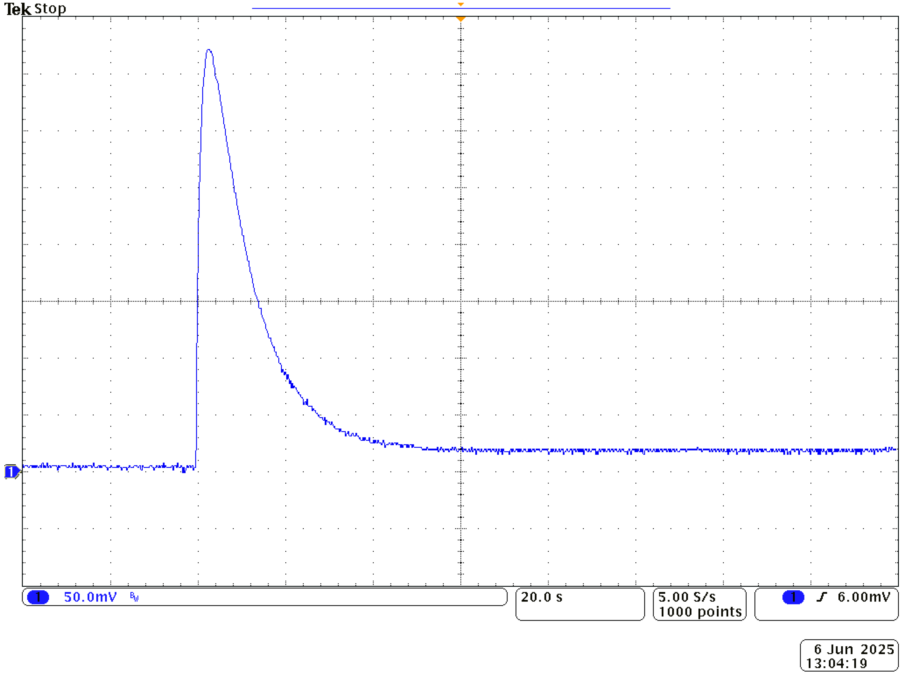
To clarify the meaning of the “thermalization” term, in
Figure 2 we plot the voltage of a TEM with 3 Ω load. Till the 40th second the TEG had ambient temperature, so there was no output voltage. In the 40th second it had been attached to the heat source
Th = 50 °C. We can see a rapid change in the output voltage to about 370 mV in a transient state, and after 100 s from the beginning of the experiment we can observe that the output voltage is steady. It means that the temperature difference at both sides of the TEM is constant.
The article gives insight into the modeling of thermalization state with varying convective thermal resistance between TEG cold plate and the ambient environment taken into account. The proposed electrothermal model of a thermalization case allows estimation of available small pieces of harvested energy and is a foundation for more advanced investigations of pulsed mode of operation.
This article is organized as follows: in
Section 2 we describe refinement and calibration of the TEM TEC1-12706-SR electrothermal model for LTspice simulations. In
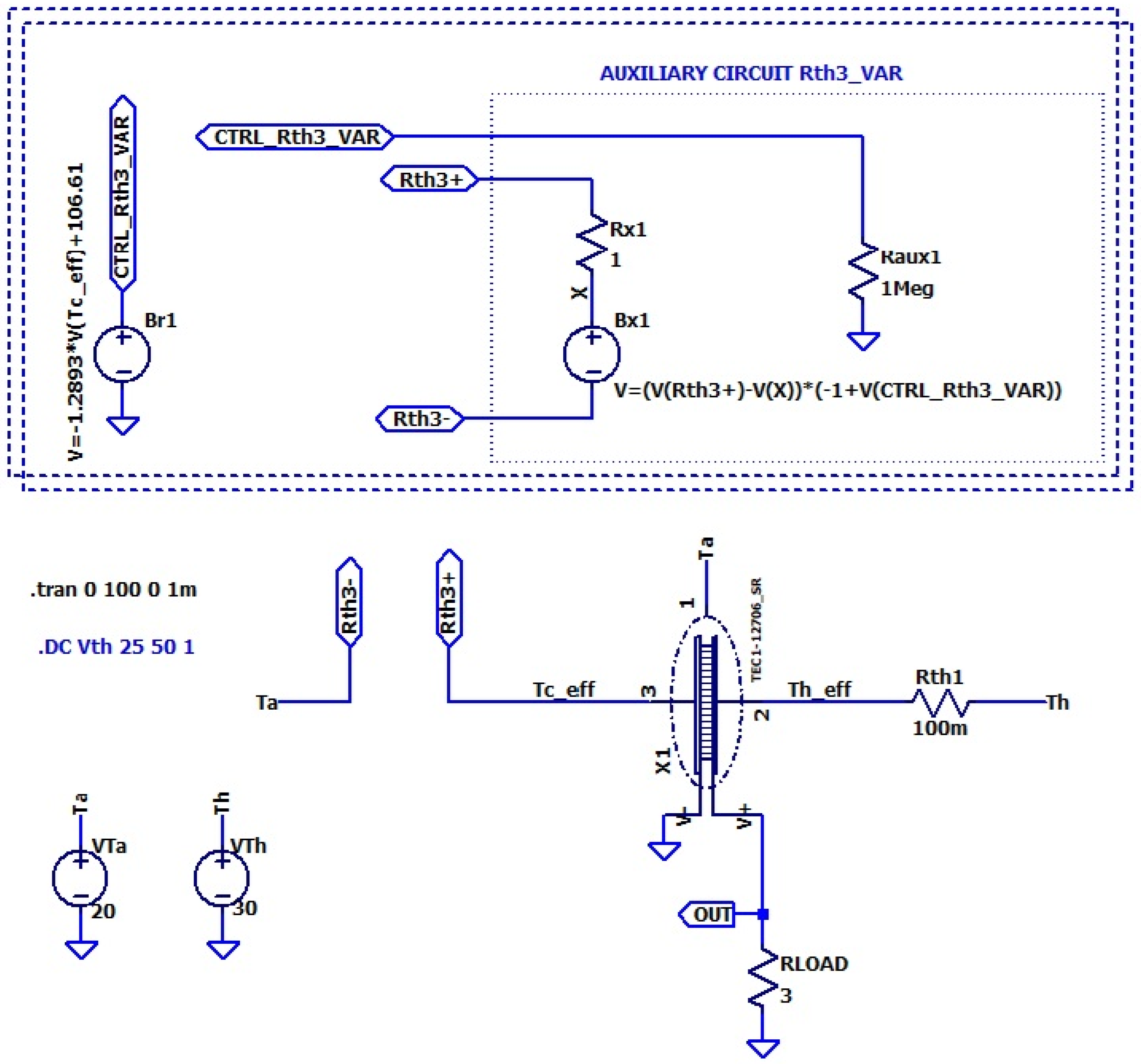
Section 3, we present a detailed electrothermal model of a heatsink-less thermoelectric generator in a thermalization state and with a variable convective thermal resistance to the ambient environment taken into account.
Section 4 deals with experiments and verification of the measurements against simulation results. Finally, in
Section 5 we discuss the obtained results and derive conclusions.
2. Thermoelectric Module Model for LTspice Simulations
Based on prior studies and experiments [
8,
9,
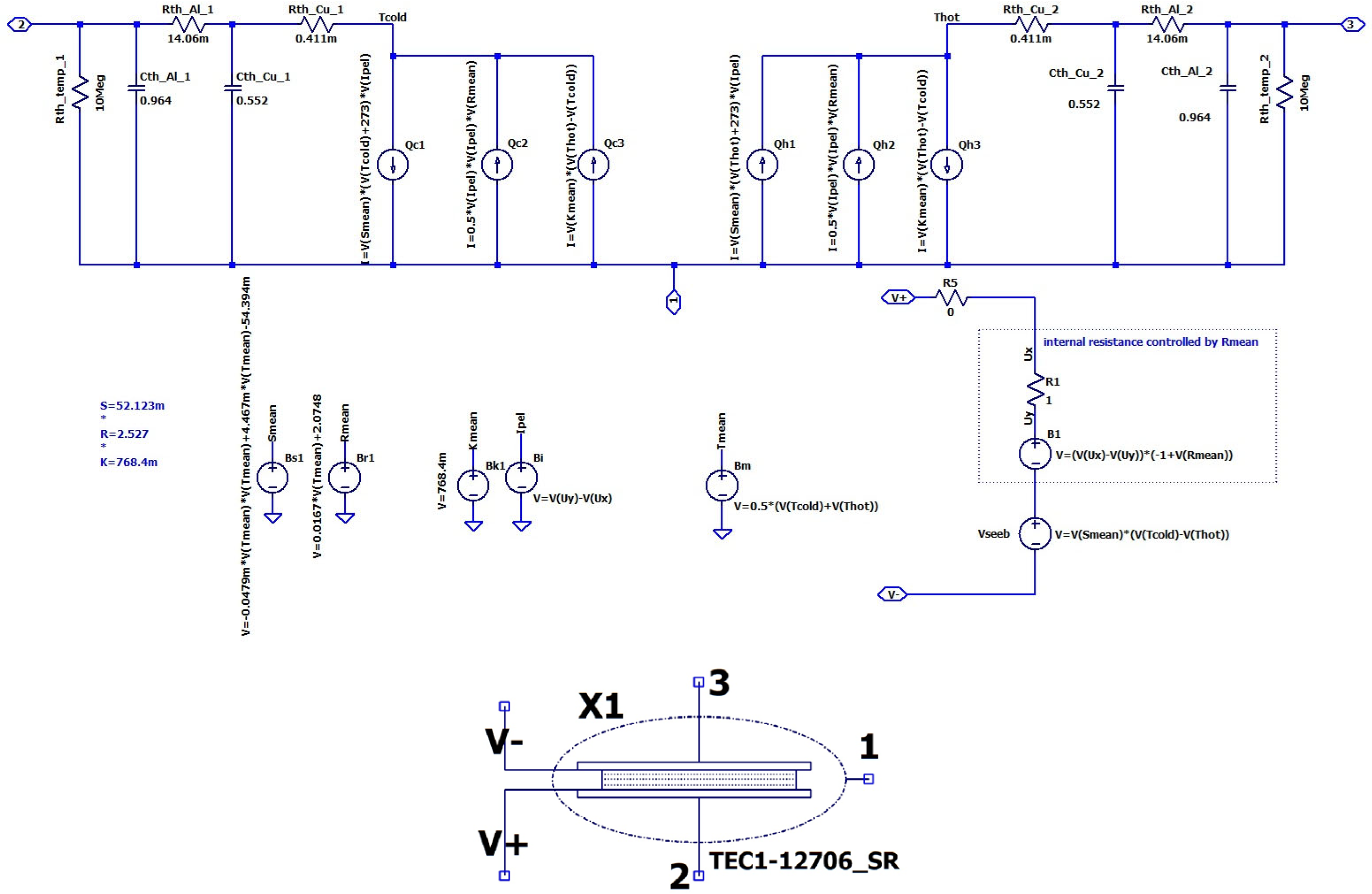
12], the authors refined/calibrated the electrothermal model of the TEM implemented into the LTspice circuit simulator (
Figure 3) and next used for investigating the thermalization process. The calibration process was based on finding the temperature functions of the Seebeck coefficient
S [V/K] and internal resistance
R [Ω] of the TEC1-12706-SR thermoelectric module.
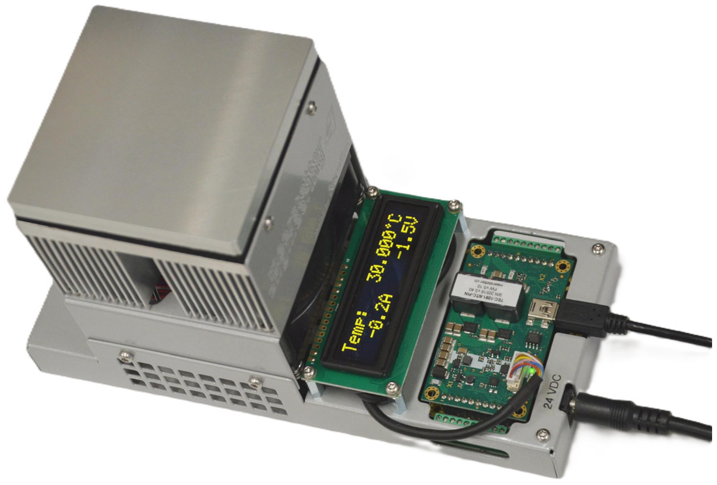
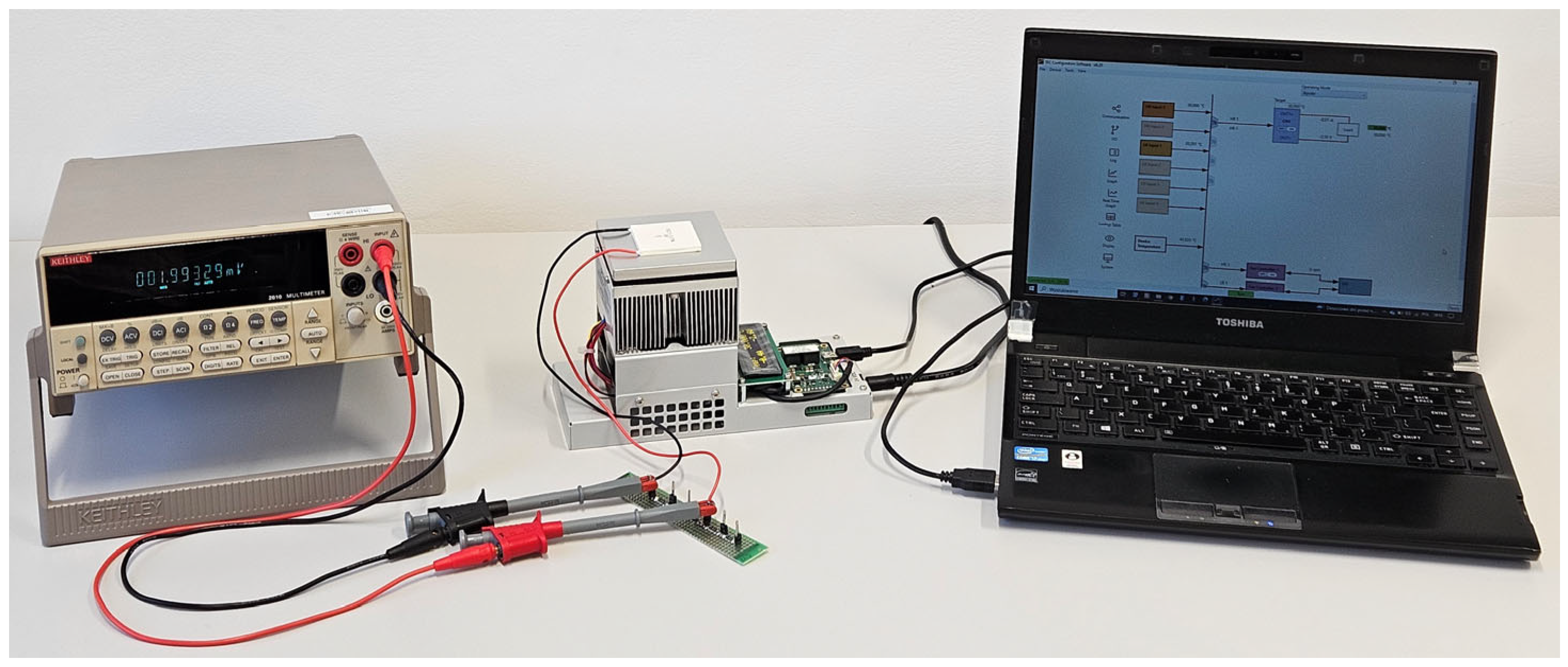
For this purpose, a dedicated laboratory stand was prepared consisting of two temperature-controlled heat sources made of temperature controllers SKT-1165 (delivered by Meerstetter Engineering), providing cooling capacity in the range of 42 W and maximum heat pumping capacity 108 W (
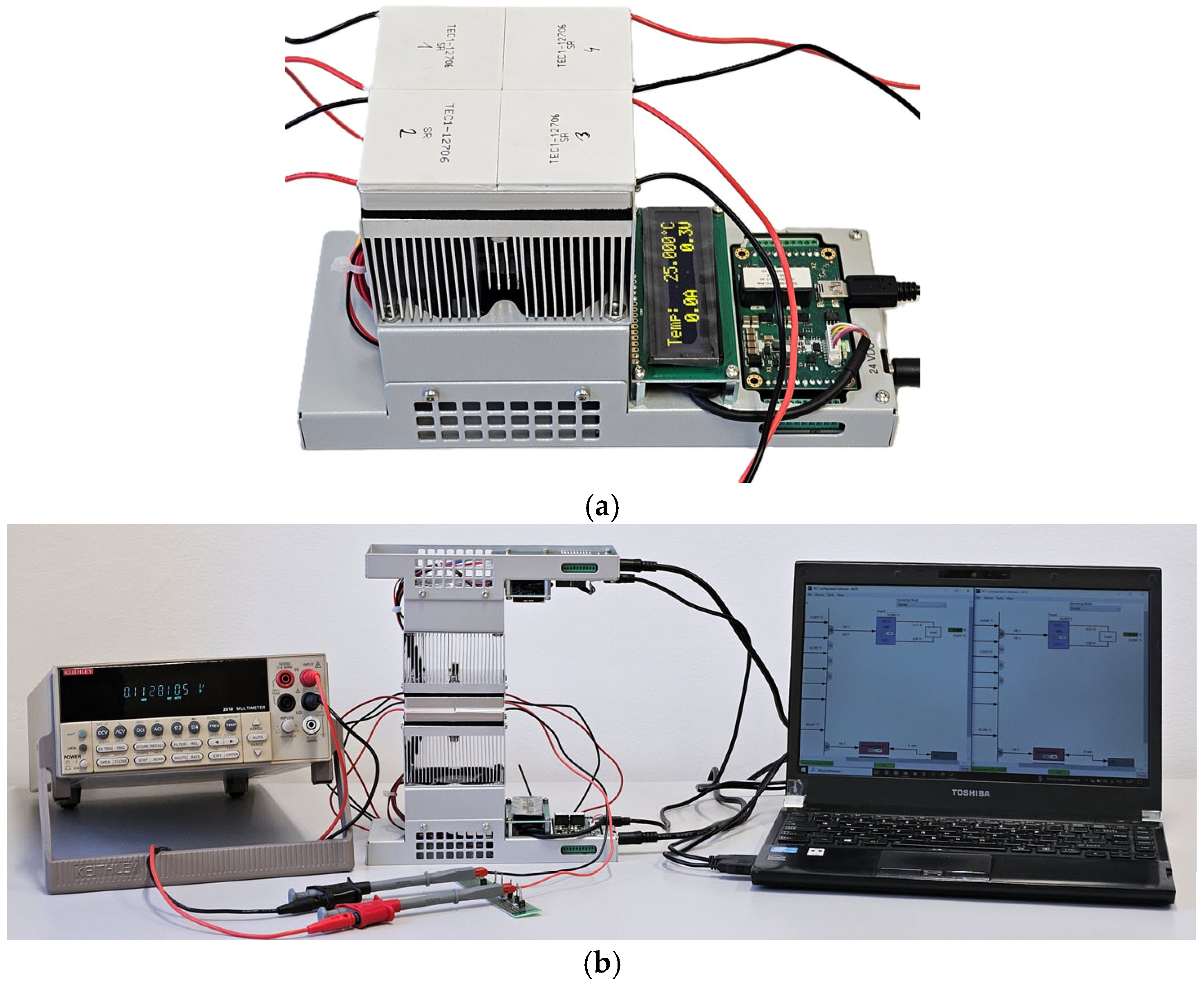
Figure 4). Then, four the same TEC1-12706-SR modules were placed thermally in parallel (
Figure 5a) between two plates of the controlled heat sources and subjected to varying/controlled temperature gradients
ΔT = Th − Tc (
Figure 5b). At the same time the Seebeck voltage
VS of the TEM was measured at open-circuit case as well as when loaded with a known
RLOAD resistor. The
Th and
Tc temperatures were set to specific values via a dedicated computer application, creating set of relatively small temperature gradients across the TEM under test. An additional voltmeter measured the output voltage of the TEM, making it possible to determine the Seebeck voltage
VS and the output voltage
VOUT when the TEM was connected to the
RLOAD.
For a given imposed temperature gradient
ΔT = Th − Tc, based on the measurements of the
VS and
VOUT, the Seebeck
S and internal resistance
R coefficients were calculated individually for each of the four TEMs subjected to testing, according to Formulas (1) and (2), respectively. Then, the estimated
S and
R for each TEM were averaged to increase the accuracy and credibility of the refined and calibrated TEC1-12706-SR model.
The averaged values of S and R were assigned to a mean value of Th and TC. In the next steps the same absolute value of temperature gradient was shifted towards higher temperatures to estimate next following S and R against the mean value of the temperature and in this way the temperature function of the two crucial parameters of the TEM were experimentally determined.
3. Electrothermal Model of the Thermoelectric Generator in a Thermalization State
The thermoelectric generator model in the thermalization state (
Figure 6) is based on the Peltier-module TEM model presented in
Section 2. The model was expanded by adding extra thermal resistance
Rth1 representing the contact resistance between the heat source and the module, the load resistance
RLOAD connected to the output of the TEM, and a convective thermal resistance
Rth3 connecting the TEM cold side to the ambient environment.
In developing the thermalization model, we also took into account that convective cooling efficiency varies with the temperature of the heated object and it is not a constant value; in other words, the convective thermal resistance changes with the cold-side temperature of the TEM. Therefore, the Rth3 was treated as a variable resistance Rth3_var.
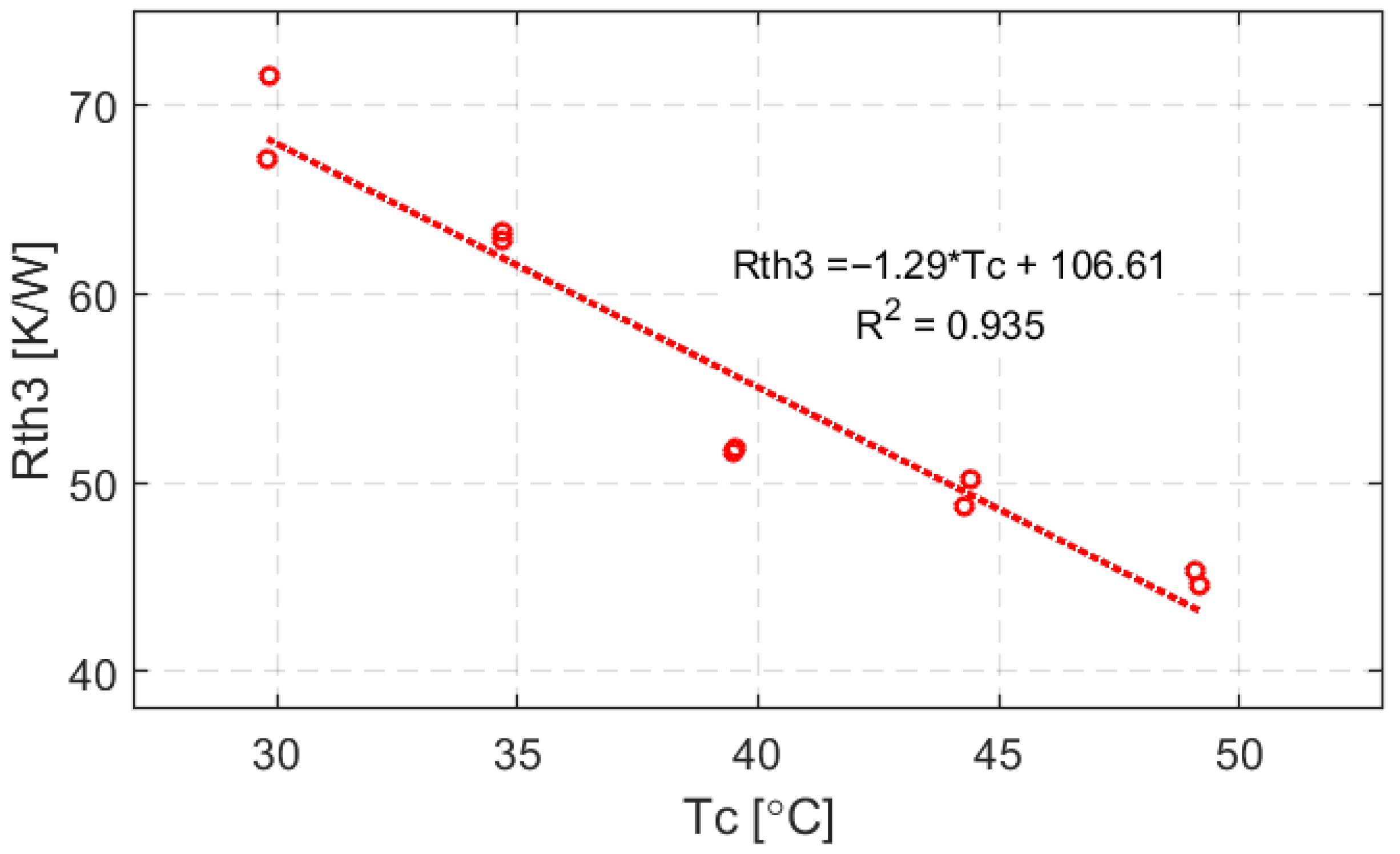
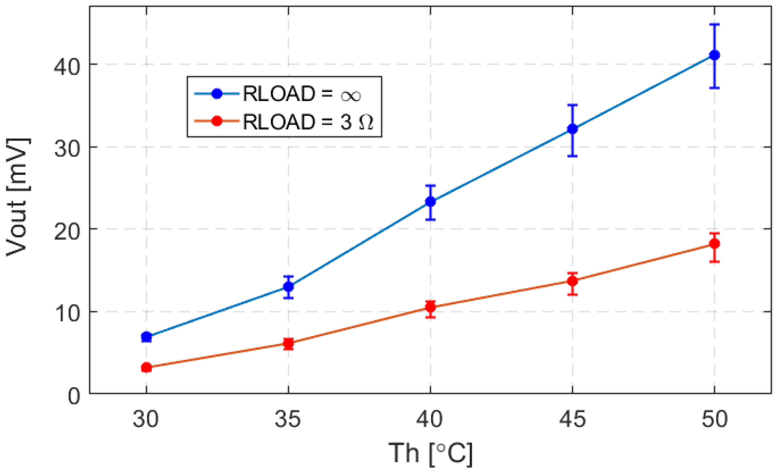
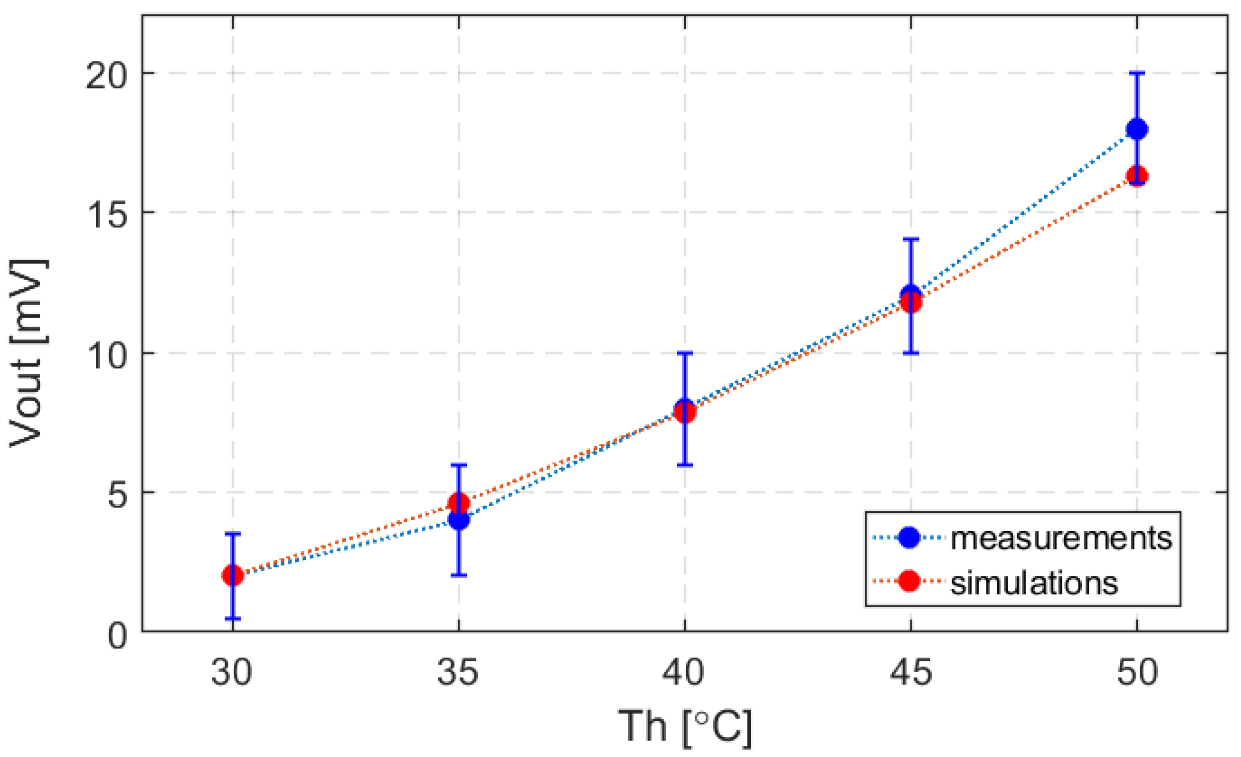
As a result of the studies, the values of the thermal resistance to the ambient environment were determined as a function of the module’s cold-side temperature. In order to obtain the temperature characteristic of the convective thermal resistance, the output voltage measurements were taken for various hot-side temperatures (30, 35, 40, 45, and 50 °C) and the ambient temperature of 20 °C. At the same time the thermoelectric module’s output was connected to the RLOAD and next without any load (open circuit). We repeated the experiments four times and we used the average values. For the obtained experimental data, the value of the Rth3 was estimated during simulations to achieve consistency with the output voltage values (measured and simulated) with the accuracy reaching tens of a millivolt. Once the expected consistency was achieved, the model (simulation) was used to determine the temperature of the thermoelectric module’s cold side, because it is in direct contact with the ambient environment and influences the convection process.
The ultimate results are shown in
Figure 7. As was expected, when the cold-side temperature increases, the thermal resistance to the ambient environment decreases.
The convective thermal resistance was approximated by a linear Equation (3) which completes the model for simulating the thermalization state of the heatsink-less TEG.
5. Conclusions
In the work, a refined electrothermal model of the thermoelectric module TEC1-12706-SR was presented. It was next developed into a model of the heatsink-less thermoelectric generator (TEG) implemented into the LTspice circuit simulator. The model was calibrated using experimental measurements of the open-circuit Seebeck voltage of the TEM as well as the output voltage when the TEM was connected to a resistive load under controlled temperature gradients. It allowed accurate reproduction of the module’s real thermoelectric characteristics.
Comparison with experimental results shows that the simulation closely reproduces the TEG’s performance. Over the range of operating conditions tested, the simulated output voltages and output powers remain within 10–17% of the measured values. This level of accuracy can be considered as a very good representation of the real behavior of the heatsink-less TEG system, regarding the thermal domain, complex nonlinear operation of the TEM, and many factors affecting its overall operating conditions.
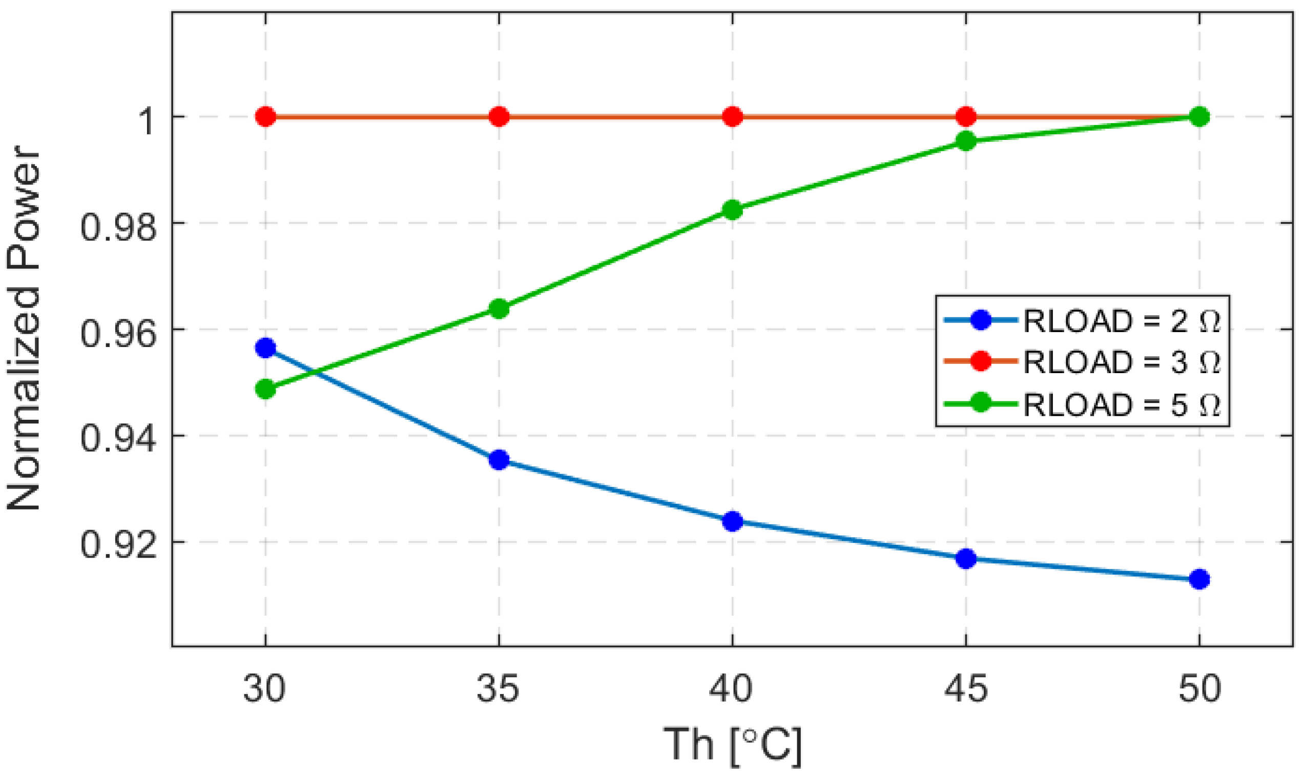
The studied thermalization process (i.e., the natural equalization of temperature between the hot and cold sides of a TEG in the absence of a heatsink) under different load resistances revealed relevant insights into the TEG system optimization. In particular an optimal load resistance of about 3 Ω was identified, which ensures the maximum output power transfer from the TEG. Lower or higher load resistances than this optimal value result in a significant reduction in output power. This is consistent with the principle of maximum power transfer when the internal resistance of the module R is equal to the external resistive load RLOAD. These findings highlight the importance of proper load matching in heatsink-less TEG applications.
By eliminating the need for a heatsink, the energy-harvesting system significantly reduces its size and weight, which is desirable for portable energy-harvesting applications. However, the lack of a dedicated cooling element means that the device’s temperature difference will equalize over time, significantly limiting the steady-state output power.
The developed electrothermal model is a useful tool for predicting and optimizing the performance of heatsink-less thermoelectric generators. The experimental results confirm that thermoelectric generators can operate effectively without extra cooling components, dissipating excessive heat to the ambient environment. The model supports the integration of TEGs into energy-harvesting systems where minimal mass and volume are critical. The significance of the proposed model lies in high consistency of the proposed LTspice model with the measurements obtained from experiments. The model can be used to simulate applications of TEG in wearable electronics where body heat can be used to power electronic devices and the heatsink area and mass should be as small as possible or even completely removed. To the best of our knowledge, the proposed LTspice model is the first one that takes into account the thermalization process.
Regarding the simplicity of the overall TEG electrothermal model implemented into the LTspice (it assumes only unidirectional 1D heat flow, which is in fact a good approximation of a real case) and the opportunity to investigate both thermal and electrical phenomena within the same simulation runs, the achieved accuracy is sufficiently good.
Future applications can leverage the presented model to design next-generation autonomous, self-powered IoT devices and wearable electronics. Optimizing the load conditions and appropriately managing the thermalization process, with the extension to pulsed-mode of operation, will enable the use of heatsink-less TEGs in sustainable energy-harvesting scenarios.

