Abstract
Vortex tubes are used in specialized scenarios where conventional refrigeration systems are impractical, such as tool cooling in CNC machines. The internal flow within a vortex tube is highly complex, with numerous factors influencing its energy separation process, and the coefficient of performance for refrigeration is relatively low. To investigate the impact of nozzle type on energy separation performance, vortex tubes with straight-type, converging-type, and converging–diverging-type nozzles were designed. Numerical simulation was conducted to explore their velocity, pressure, and temperature distribution at an inlet pressure of 0.7 MPa and a cold mass fraction of 0.1~0.9. The cooling effect, temperature separation effect, cold outlet mass flow rate, and refrigeration capacity of vortex tubes were assessed. The converging–diverging nozzle increases the gas velocity at the nozzle outlet while it does not significantly enlarge the airflow velocity in the vortex chamber. As the cold mass fraction rises, the cooling performance and cooling capacity of three vortex tubes first increase and then decrease. The maximum cooling effect and cooling capacity of vortex tubes are achieved at cold mass fractions of 0.3 and 0.7, respectively. Under identical conditions, the vortex tube with a converging nozzle achieves the highest cooling effect with a temperature drop of 36.6 K, whereas the vortex tube with converging–diverging nozzles possesses the largest gas flow rate, and the cooling capacity reaches 542.4 W. The vortex tube with straight nozzles exhibits the worst refrigeration performance with a cooling effect of 33.6 K and a cooling capacity of 465.9 W. It is indicated that optimizing the nozzle structure of the vortex tube to reduce flow resistance contributes to enhancing both the gas velocity entering the swirl chamber and the resultant refrigeration performance.
1. Introduction
The vortex tube was invented by Ranque in 1931, which can separate compressed gas into cold and hot streams without moving parts [1,2,3]. With its simple structure, ease of use, quick activation, and reliable operation, it can adapt to refrigeration in high temperatures, high pollution, and other harsh environments. But it has a low performance coefficient (COP). It is commonly used in specialized scenarios where inexpensive compressed gas is available or conventional refrigeration systems are impractical, such as tool cooling in CNC machines, control cabinet cooling near high-temperature equipment, and gas separation applications [4,5].
The performance of a vortex tube is influenced by operational conditions including inlet pressure, cold-end tube outlet pressure, cold mass fraction, and working fluid properties, as well as structural parameters such as nozzle type, number of nozzles, nozzle angle, cold-end tube diameter, hot-end tube diameter, main tube length, hot-end regulating valve taper, and vortex chamber radius [2,3]. As early as 1947, Hilsch [6] investigated the influence of the vortex tube structural parameters on its energy separation characteristics of compressed air. The increment of inlet pressure can effectively enhance the tangential rotational velocity and the energy transfer from the outside to the inside of vortex tube significantly, thus improving the energy separation, but it has little influence on the axial and radial velocity. The cooling and heating effect of vortex tube first increases and then decreases with the increment of inlet pressure [7,8,9]. Different results were reported concerning the influence of the number of nozzles on the energy separation performance of the vortex tube [10,11]. Manickam and Prabakaran [12] reported that the cold end diameter to tube diameter ratio influenced the performance of the vortex tube. Shaji et al. [13] found a strong correlation between vortex tube convergence angle and swirl flow intensity distribution, favoring the improvement of temperature separation. For different gases, molecular weight and specific heat capacity significantly influence the velocity and temperature distributions within the vortex tube. Both hot and cold temperature separations increase for higher specific heat ratios of the gas, but the performance coefficient of the vortex tube remains majorly unaffected for different gases. For helium, neon, nitrogen, argon, and carbon dioxide, the cold air temperature drop ΔTc increases by about 80–90% when the inlet pressure pi increases from two bar to four bar. When pi increases from four bar to six bar, ΔTc increases by about 10–20%, and when pi increases from six bar to eight bar, the increase in ΔTc is less than 10% [14,15]. Vortex tubes with specialized configurations such as double circuit vortex tube parallel vortex tubes, and large-caliber vortex tubes have also been investigated [16,17,18]. In recent years, different numerical simulation methods have been widely employed in vortex tube research. Dutta compared the standard k–ε, RNG k–ε, standard k–ω, and SST k–ω turbulence models in predicting the temperature separation in a Ranque–Hilsch vortex tube. The results show that among all the turbulence models, temperature separation predicted by the standard k–ε turbulence model is closer to the experimental results [19]. He et al. [20] investigated the design optimization of vortex tube structure by numerical simulation and orthogonal analysis.
To design appropriate vortex tubes and improve the energy separation efficiency, extensive experimental and numerical studies have been conducted. However, the flow in a vortex tube is so complex that the energy separation mechanisms are still not fully elucidated. This results in the absence of a universal standard method for vortex tube design. When it comes to the structural optimization of vortex tubes, selecting the inlet nozzle type is a step of critical importance. In the past, due to constraints in manufacturing techniques, vortex tubes commonly employed constant cross-section flow channels for their inlet nozzles, and the comparative studies on the influence of different nozzle types are still limited.
To investigate the effect of nozzle type on energy separation, vortex tubes with straight-type, converging-type, and converging–diverging-type nozzles were designed in this study, and the internal flow was studied through numerical simulations under conditions of cold mass fraction ranging from 0.1 to 0.9 and inlet compressed air gauge pressure at 0.7 MPa, which can provide a reference for selecting the inlet nozzle type in vortex tube design.
2. Numerical Model
2.1. Physical Model
The vortex tube is mainly composed of an inlet nozzle, vortex chamber, separation orifice plate, hot tube, cold tube, and a control valve.
As shown in Figure 1, the length of the hot tube and cold tube are 210 and 106 mm, respectively. The inner diameter of hot tube and cold tube is 21 mm. The thickness of separation orifice plate is 5 mm. The central aperture is 10.6 mm. The width of ring gap at hot outlet is 1.4 mm.
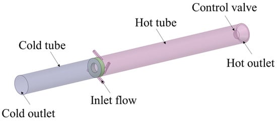
Figure 1.
Geometrical model of the vortex tube.
Figure 2 shows the structure of three inlet nozzles designed in this study. The cross-section of the flow channel at the inlet nozzle is square. Their specific geometrical parameters are listed in Table 1.
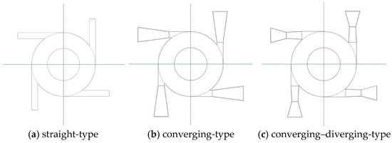
Figure 2.
Inlet structure of vortex tube.

Table 1.
Geometrical parameters of inlet flow channels in the vortex tube.
2.2. Governing Equations
When the vortex tube operates steadily, the airflow within it is a three-dimensional, steady, compressible, viscous turbulent flow, which was described with the continuity equation, momentum equation, and energy equation [14].
Mass equation:
Momentum equation:
Energy equation:
Ideal gas equation of state:
where is the density, are the Cartesian coordinates (i = 1, 2, 3), is the velocity component in the direction, is the pressure, is the dynamic viscosity, is the total enthalpy, is the temperature, is the Kronecker delta tensor, is the Reynolds stress tensor, is the effective thermal conductivity, is the effective viscous stress tensor, and is the gas constant.
2.3. Turbulence Model
The impact of different turbulence models on the accuracy of numerical simulation for vortex tubes has been investigated in previous studies [19]. It is indicated that the standard k–ε model is the optimal turbulence model in terms of computational accuracy, computational resources, and computation duration. Therefore, the standard k–ε model was adopted in this study.
2.4. Boundary Conditions
The inlet of nozzles is set as pressure inlet. The inlet pressure and temperature are determined as 0.7 MPa and 298 K, respectively. The outlet for cold outlet and hot outlet is set as pressure outlet. The cold outlet pressure is set as standard atmospheric pressure while the hot outlet pressure is adjustable to obtain different cold mass fractions. The inner wall of vortex tubes is determined to be an adiabatic no-slip wall. The working fluid is air, considered as a compressible ideal gas.
2.5. Computational Methods
The solution of this steady-state process uses the SIMPLE algorithm. The pressure equation is discretized using a second-order scheme. The equations for density, energy, turbulent kinetic energy, and turbulent dissipation rate are all discretized using a second-order upwind scheme. The solution is considered to be converged when the residuals of parameters such as energy and turbulent kinetic energy fall below 10−6.
2.6. Mesh Model and Grid Independence Verification
The three-dimensional geometric models of vortex tubes were constructed with SolidWorks 2023, and then meshed using a poly-hexcore scheme in fluent meshing, generating hexahedral cells in the core region of the flow domain while creating polyhedral cells with local refinement in the near-wall regions. The skewness was controlled under 0.6. As an example, a mesh model of the vortex tube with straight nozzles is shown in Figure 3.

Figure 3.
Mesh model of the vortex tube with straight nozzles.
Grid independence verification was conducted to ensure computational accuracy while minimizing resource consumption [18,19]. For the vortex tube with converging–diverging nozzles working at inlet pressure of 0.7 MPa, inlet air temperature of 298 K, and cold mass fraction of 0.5, the influence of grid numbers on the cooling effect is shown in Figure 4. When the number of mesh elements exceeds 270,000, the cooling effect of the vortex tube keeps stable at approximately 31.7 K, meeting the requirement of grid independence. Through the grid independence verification, the grid numbers for the vortex tube models with straight, converging, and converging–diverging nozzles are 280,000, 300,000, and 310,000, respectively.
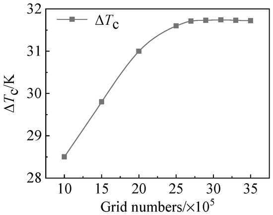
Figure 4.
Relationship between grid numbers and cooling effect.
2.7. Model Validation
To verify the reliability of the numerical simulation method, the vortex tube performance experiments conducted by Xue et al. [8] were simulated using Fluent in ANSYS 2023 R1, and the results were compared with experimental data. As shown in Table 2, for different cold mass fractions , the relative error between the simulated and experimental results of the cooling effect remains within 5%, demonstrating the satisfactory reliability of the numerical model.

Table 2.
Comparison of simulated and experimental cooling effect.
3. Results and Discussion
3.1. Influence of Nozzle Structure on Energy Separation Efficiency
Several indicators are adopted for evaluating the energy separation efficiency of vortex tubes.
Cold mass fraction:
Cooling effect:
Temperature separation effect:
Refrigeration capacity:
where and are the mass flow rates of inlet air and cold air at the cold outlet of the vortex tube, respectively, in kg/s. , and are the gas temperatures at the inlet, cold outlet, and hot outlet, respectively, K. is the specific heat capacity, J/(kg·K). is the gas temperature difference between the hot outlet and the cold outlet, K.
When the inlet gas pressure is constant at 0.7 MPa and the cold mass fraction ranges from 0.1 to 0.9, the variation in cooling effect, temperature separation effect, and refrigeration capacity with inlet nozzle structures is shown in Figure 5.
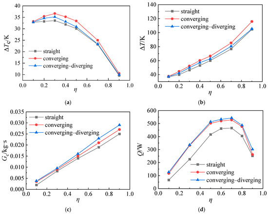
Figure 5.
Variation in (a) cooling effect, (b) temperature separation effect, (c) air mass flow rate at cold outlet, and (d) refrigeration capacity with cold mass fraction for vortex tubes with different inlet nozzles.
In Figure 5a, when the cold mass fraction increases from 0.1 to 0.9, the cooling effect of the vortex tube first increases and subsequently declines. At the cold mass fraction of 0.3, three vortex tubes have the maximum cooling effect. As the cold mass fraction ascends from 0.1 to 0.3, the cooling effect of vortex tubes rises gently. When the cold mass flow rate exceeds 0.3, the cooling effect of vortex tubes declines sharply. At the cold mass fraction of 0.3, the vortex tube with converging nozzles has the highest cooling effect, reaching 36.6 K, followed by the vortex tube with converging–diverging nozzles (35.2 K). And the vortex tube with a straight nozzle has the smallest cooling effect of 33.6 K.
Under specified inlet pressure and temperature conditions, the temperature drop at the cold outlet of a vortex tube demonstrates a characteristic non-monotonic relationship with cold mass fraction. It initially increases before subsequently decreasing. This behavior stems from the competing influences of enhanced vortex intensity and detrimental thermal mixing effects. During the initial phase, increased cold mass fraction strengthens the suction effect in the core region, promoting the transition from free vortex to forced vortex flow. This intensifies the centrifugal separation mechanism, thereby improving energy transfer efficiency and resulting in greater temperature reduction. However, beyond the optimal cold mass fraction threshold, excessive gas extraction causes accelerated turbulent mixing between counterflowing streams. The consequent reduction in residence time for the cold stream, combined with enhanced entrainment of high-temperature fluid, reduces the net cooling effect per unit mass of cold air, leading to a decline in temperature drop. Consequently, the vortex tube exhibits a well-defined operating point that maximizes its refrigeration performance.
As shown in Figure 2, the inlet area of a straight nozzle is only 4 mm2, and that of the converging nozzle or the converging–diverging nozzle is 22.09 mm2. This leads to higher velocity and flow resistance at the straight nozzle inlet. According to Bernoulli’s equation, the velocity of air entering the swirl chamber from the nozzle outlet decreases, consequently leading to a reduction in the refrigeration effect. In comparison, converging nozzles and converging–diverging nozzles exhibit lower flow resistance, resulting in higher gas velocity entering the swirl chamber and consequently enhancing the refrigeration effect.
Figure 5b shows the impact of cold mass fraction on the temperature difference between the cold outlet and hot outlet of vortex tubes, namely the temperature separation effect. The maximum temperature separation effect of vortex tubes is observed at the cold mass fraction of 0.9. This is attributed to the continuous increase in the hot-end temperature rise with the elevation of the cold mass fraction. Among them, the vortex tube with converging-type nozzles has the best temperature separation effect, reaching 115.9 K, followed by the vortex tube with converging–diverging-type nozzles (105.3 K). And the vortex tube with straight-type nozzles has the worst temperature separation effect (104.7 K).
The evolution of cold air mass flow rate with the cold mass fraction is demonstrated in Figure 5c. For three types of vortex tubes, the cold air mass flow rate shows an upward trend as the cold mass fraction rises from 0.1 to 0.9. Furthermore, the air mass flow rate at the cold outlet of vortex tubes follows a downward trend as converging–diverging-type nozzles > converging-type nozzles > straight-type nozzles, which is caused by the difference in nozzle flow resistance.
As indicated in Figure 5d, the refrigeration capacity of vortex tubes shows parabola-like shape as the cold mass fraction increases. The maximum refrigeration capacity is observed at the cold mass fraction of 0.7. Their values are 542.4 W (converging–diverging-type nozzles), 527.9 W (converging-type nozzles), and 465.9 W (straight-type nozzles). Equation (8) reveals that for a given specific heat capacity, the refrigeration capacity of the vortex tube is directly proportional to the product of the cooling effect and the mass flow rate of cold air . As shown in Figure 5a, the cooling effect initially increases and then decreases with the cold mass fraction, reaching its maximum value at a cold mass fraction of 0.3. Meanwhile, Figure 5c reveals that the cold-end air flow rate exhibits an approximately linear growth with increasing cold mass fraction. When the cold mass fraction is very low, both the cooling effect and cold-end air flow rate remain at low levels. Conversely, when the cold mass fraction is high, although the cold-end air flow rate is substantial, the cooling effect becomes significantly reduced. This inverse relationship results in the refrigeration capacity first increasing and then decreasing with rising cold mass fraction.
In summary, the vortex tube with converging-type nozzles has the highest cooling effect. The cooling effect of a vortex tube with converging–diverging-type nozzles is lower than that of a vortex tube with converging-type nozzles, but it has a higher air mass flow rate at the cold outlet. Herein, larger refrigeration capacity can be expected. However, the cooling effect and refrigeration capacity of the vortex tube with straight-type nozzles are significantly lower than those of the other two types of vortex tubes.
3.2. Influence of Nozzle Structure on Temperature Distribution
Figure 6 shows the total temperature distribution along the Y-Z axial cross-section of three vortex tubes. The gas temperatures at the cold outlet and hot outlet of three vortex tubes are listed in Table 3. In Figure 6, following the energy separation in vortex tubes, the gas temperature at the hot outlet in the center gradually decreases toward the separation orifice plate, while the gas temperature gradually increases from the center of the vortex tubes toward the wall. The cold gas flows through the central hole to the cold tube, and the hot gas flows out through the hot annular gap along the wall.
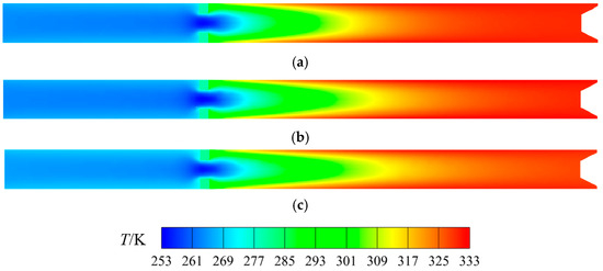
Figure 6.
Axial total temperature distribution of vortex tubes. (a) Straight-type, (b) converging-type, (c) converging–diverging-type.

Table 3.
Temperatures at hot outlet and cold outlet of vortex tubes.
As can be seen in Table 3, the vortex tube with converging nozzles has the lowest cold outlet temperature and the highest hot outlet temperature. Therefore, the largest temperature difference between the cold outlet and hot outlet can be expected, followed by the vortex tube with converging–diverging nozzles and the vortex tube with straight nozzles.
3.3. Energy Separtion Mechanism Analysis: Influence of Nozzle Structure on Velocity and Pressure Distribution
The velocity distribution on the central plane of nozzles in three types of vortex tubes is shown in Figure 7. For the straight-type nozzle, due to the influence of the flow channel structure, the airflow can only maintain a subsonic flow state in the channel, and the velocity changes little. For the converging-type nozzle, the fluid also flows within the passage in a subsonic state. The large inlet cross-sectional area of nozzles causes slow airflow into the passage. As the cross-sectional area of passage decreases gradually, the air velocity ascends continuously, reaching its maximum value at the throat outlet. For the converging–diverging-type nozzle, the flow characteristics in the converging section are like those of converging nozzles. After reaching the critical velocity at the throat, the air velocity will continue to increase to supersonic in the diverging section.

Figure 7.
Velocity distribution in the cross-section of nozzles.
When the airflow passes through the nozzle and enters the vortex chamber, it is impacted by the upstream nozzle flow, and they mix, causing the reduction in velocity. As the pressure rapidly drops, the airflow volume expands. Herein, the air velocity significantly increases. The maximum velocity is achieved near the tangent area between the nozzle and the vortex chamber wall. Subsequently, the velocity gradually decreases due to the resistance from the flow of the downstream nozzle. The airflow undergoes high-speed rotation under the guidance of the vortex chamber wall.
The maximum velocity varies in the vortex chamber of different vortex tubes. The maximum velocity in the vortex chamber with straight-type nozzles is 497 m/s, while the maximum velocity in the vortex chamber with converging-type nozzles reaches 506 m/s. The maximum velocity in the vortex chamber with converging–diverging-type nozzles is in between (501 m/s). In contrast, the high-speed region along the circumferential direction within the converging-type nozzles is larger, favoring the energy separation. In the straight-type nozzles, the lowest airflow velocity is at the nozzle outlet, alongside the small initial momentum and the lowest rotational speed in the vortex chamber. In the converging–diverging-type nozzles, although the flow velocity at the nozzle outlet is significantly higher than that of straight-type nozzles and converging-type nozzles, the jet rigidity is also related to the gas density. Since the outlet area of the diverging section in the converging–diverging-type nozzles is significantly larger than that of converging-type nozzles, the pressure and density of airflow continue to decrease greatly in the diverging section, which is adverse to increasing the mass flow rate of the airflow at the nozzle outlet section, and the potential for further expansion and acceleration after entering the swirl chamber reduces. Therefore, the gas velocity in the swirl chamber cannot be significantly increased.
Figure 8 shows the contour plot of axial velocity distribution in the vortex tube, revealing a distinct reverse flow phenomenon within the device. As observed from the figure, the direction of axial velocity reverses completely from the central axis to the peripheral region. Specifically, the outer periphery exhibits hot fluid flowing from the cold-end orifice plate toward the hot-end exit, while the core region shows cold fluid moving backward to the cold-end orifice plate due to the obstruction effect of the hot-end control valve. In terms of maximum axial velocities, the straight-channel nozzle vortex tube achieves 92 m/s for hot fluid and 158 m/s for cold fluid; the converging nozzle configuration maintains 92 m/s for hot fluid while increasing cold fluid velocity to 167 m/s; whereas the converging–diverging nozzle design further enhances the performance with hot fluid reaching 96 m/s and cold fluid attaining the highest velocity of 184 m/s.
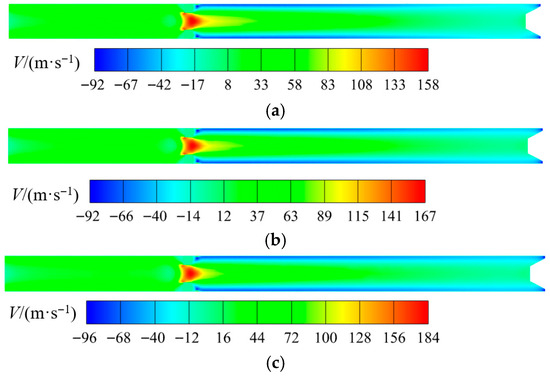
Figure 8.
Axial velocity distribution in Y-Z cross-section of vortex tubes. (a) Straight-type, (b) converging-type, (c) converging–diverging-type.
The pressure distribution in the cross-section of nozzles is shown in Figure 9. It indicates that in the straight-type and converging-type nozzles, the pressure of airflow continuously decreases, and the velocity continuously increases from the nozzle inlet to the tangential region of the vortex chamber. In the converging–diverging-type nozzles, the airflow expands to a very low pressure in the diverging section of nozzles, reaching a supersonic state. Then it decelerates and increases the pressure near the nozzle outlet. And secondary expansion and acceleration occur.

Figure 9.
Pressure distribution in the cross-section of nozzles.
Figure 10 shows the static pressure distributions in the Y-Z cross-sections of three vortex tubes, respectively. There is a pressure gradient in the radial direction of the vortex chamber. The pressure at the center is the lowest, and as the radial distance increases, the pressure rises gradually and reaches the maximum near the wall. In the axial direction, when the compressed air flows through the vortex chamber to the hot outlet, the pressure gradually increases. The radial and axial pressure gradients cause part of the gas to flow reversely through the center of vortex tubes. And the gas enters the cold tube through the central hole of the separation orifice plate. The central area has the largest negative pressure, alongside the small pressure gradient. However, the central negative pressure areas of vortex tubes with converging-type nozzles and converging–diverging-type nozzles are smaller, and a larger pressure gradient exists near the central hole of the separation orifice plate.
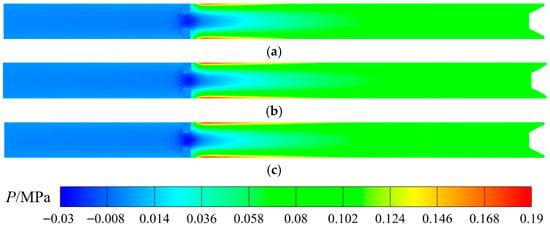
Figure 10.
Static pressure distribution in Y-Z cross-section of vortex tubes. (a) Straight-type, (b) converging-type, (c) converging–diverging-type.
In vortex tubes the kinetic energy from areas of large circumferential velocity is transported to the wall layer, where it is then dissipated and turned into sensible enthalpy. The viscous radial energy flux in circulating flow originates from the strong velocity derivatives in the boundary layer of the tube [21]. The airflow enters the swirl chamber tangentially at high velocity and undergoes intense rotation, consequently generating a significant velocity gradient within the flow boundary layer near the wall, which then induces energy separation through viscous heating effects. A larger radial velocity gradient in the boundary layer and slower decay of the rotational velocity, leading to a more pronounced energy separation effect. As discussed above, compared to vortex tubes equipped with straight nozzles, those utilizing converging or converging–diverging nozzles demonstrate higher rotational speeds of the internal airflow and consequently achieve superior energy separation performance.
4. Conclusions
Three vortex tubes with straight-type, converging-type, and converging–diverging-type nozzles were designed in this study. The influence of nozzle structure on the velocity, pressure, and temperature distribution, as well as the energy separation efficiency of vortex tubes, was assessed through numerical simulation. Some conclusions can be drawn below.
- (1)
- Compared with straight-type and converging-type nozzles, the converging–diverging-type nozzles can increase the gas velocity at the nozzle outlet, while they cannot significantly increase the gas velocity in the vortex chamber.
- (2)
- With the increase in cold mass fraction, the cooling effect and refrigeration capacity of three vortex tubes increase first and then decrease. At the cold mass fraction of 0.3, the vortex tube has the best cooling effect, while its maximum refrigeration capacity is achieved at the cold mass fraction of 0.7.
- (3)
- Under identical conditions, the vortex tube with a converging nozzle achieves the highest cooling effect with a temperature drop of 36.6 K, whereas the vortex tube with converging–diverging nozzles possesses the largest gas flow rate, and the cooling capacity reaches 542.4 W. The vortex tube with straight nozzles exhibits the worst refrigeration performance with a cooling effect of 33.6 K and a cooling capacity of 465.9 W, which are significantly lower than those of the other two types of vortex tubes. It is indicated that optimizing the nozzle structure of the vortex tube to reduce flow resistance contributes to enhancing both the gas velocity entering the swirl chamber and the resultant refrigeration performance.
- (4)
- The present numerical study primarily focuses on the performance of three vortex tubes employing different inlet nozzle configurations at a constant pressure, while further research should incorporate experiments and consider more parameters.
Author Contributions
Conceptualization, J.Z., F.G. and B.W.; methodology, M.T.; validation, M.T.; formal analysis, G.J. and F.J.; investigation, M.T. and F.J.; resources, J.Z. and F.G.; data curation, G.J.; writing—original draft, G.J.; writing—review and editing, B.W.; supervision, B.W.; project administration, B.W.; funding acquisition, G.J., J.Z. and F.G. All authors have read and agreed to the published version of the manuscript.
Funding
This research was supported by the Science and Technology Project of State Grid Zhejiang Electric Power Co., Ltd. (5211HZ230009).
Data Availability Statement
Data involved in this study are available from the authors under reasonable request.
Conflicts of Interest
Authors Ming Tang and Gongyu Jin were employed by the company Hangzhou Power Supply Company State Grid Zhejiang Electric Power Co., Ltd. Author Jiali Zhang and Fuxing Guo were employed by the company Hangzhou Join Electric Technology Co., Ltd. The remaining authors declare that the research was conducted in the absence of any commercial or financial relationships that could be construed as a potential conflict of interest.
References
- Xue, Y.; Arjomandi, M.; Kelso, R. A critical review of temperature separation in a vortex tube. Exp. Therm. Fluid Sci. 2010, 34, 1367–1374. [Google Scholar] [CrossRef]
- Awan, O.A.A.; Sager, R.; Petersen, N.H.; Wirsum, M.; Juntasaro, E. Flow phenomena inside the Ranque-Hilsch vortex tube: A state-of-the-art review. Renew. Sustain. Energy Rev. 2025, 211, 115351. [Google Scholar] [CrossRef]
- Ambedkar, P.; Dutta, T. Analysis of various separation characteristics of Ranque-Hilsch vortex tube and its applications—A review. Chem. Eng. Res. Des. 2023, 191, 93–108. [Google Scholar] [CrossRef]
- Li, N.; Chen, G.-M. Experimental study of the coupling characteristics between a vortex tube and refrigerants. J. Eng. Thermophys. 2019, 40, 28–35. [Google Scholar]
- He, Z.; Luo, G. Automobile rinse method based on vortex tube making heat principle. Jixie Gongcheng Xuebao/Chin. J. Mech. Eng. 2005, 41, 157–160. [Google Scholar] [CrossRef]
- Hilsch, R. The use of the expansion of gases in a centrifugal gield as cooling process. Rev. Sci. Instrum. 1947, 18, 108–113. [Google Scholar] [CrossRef] [PubMed]
- He, L.J.; Li, H.Y.; Ma, W.Q.; Sun, S.Z.; Gao, W.B.; Wang, J.B. Study on the influence of inlet pressure on vortex tube on its performance. Chin. J. Vac. Sci. Technol. 2020, 40, 108–112. [Google Scholar]
- Xue, Q.Z.; Xu, L.; Zhang, R.X.; Zhang, Z.W. Experimental study on the effect of inlet pressure on cooling characteristics of vortex tube. J. Eng. Therm. Energy Power 2024, 39, 26–32. [Google Scholar]
- Chen, G.M.; Jiang, G.N.; Tang, L.M.; Li, N. Experimental study on the influence of inlet pressure on the flow parameters at the reverse flow boundary of vortex tube and its relation with energy separation performance. Exp. Therm. Fluid Sci. 2024, 156, 111211. [Google Scholar] [CrossRef]
- Shamsoddini, R.; Nezhad, A.H. Numerical analysis of the effects of nozzles number on the flow and power of cooling of a vortex tube. Int. J. Refrig. 2010, 33, 774–782. [Google Scholar] [CrossRef]
- Shamsoddini, R.; Abolpour, B. A geometric model for a vortex tube based on numerical analysis to reduce the effect of nozzle number. Int. J. Refrig. 2018, 94, 49–58. [Google Scholar] [CrossRef]
- Manickam, M.; Prabakaran, J. CFD analysis on Ranque–Hilsch vortex tube with different cold orifice diameter and cold mass fraction. Int. J. Ambient Energy 2022, 43, 1216–1229. [Google Scholar] [CrossRef]
- Shaji, K.; Narayanan, V.; Suryan, A.; Kim, H.D. Effect of convergence angle of Ranque-Hilsch vortex tube on the optimization of thermal separation in compressible swirl flow. Phys. D Nonlinear Phenom. 2025, 481, 134761. [Google Scholar] [CrossRef]
- Ambedkar, P.; Dutta, T. CFD simulation and thermo-dynamic analysis of energy separation in vortex tube using different inert gases at different inlet pressures and cold mass fractions. Energy 2023, 263, 125797. [Google Scholar] [CrossRef]
- Ambedkar, P.; Dutta, T. CFD analysis of different working gases in Ranque-Hilsch vortex tube. Mater. Today Proc. 2023, 72, 761–767. [Google Scholar] [CrossRef]
- Rafiee, S.E.; Sadeghiazad, M.M. Experimental and CFD analysis on thermal performance of Double-Circuit vortex tube (DCVT)-geometrical optimization, energy transfer and flow structural analysis. Appl. Therm. Eng. 2018, 128, 1223–1237. [Google Scholar] [CrossRef]
- Rafiee, S.E.; Sadeghiazad, M.M. Experimental and 3D CFD analysis on optimization of geometrical parameters of parallel vortex tube cyclone separator. Aerosp. Sci. Technol. 2017, 63, 110–122. [Google Scholar] [CrossRef]
- Wang, J.; Tian, Y.; Chen, C.; Lu, M.; Long, X.; Li, Y. Analysis of throttling effect of large caliber vortex tube based on fluent. Chin. J. Vac. Sci. Technol. 2023, 43, 156–162. [Google Scholar]
- Dutta, T.; Sinhamahapatra, K.P.; Bandyopd-hyay, S.S. Comparison of different turbulence models in predicting the temperature separation in a Ranque–Hilsch vortex tube. Int. J. Refrig. 2010, 33, 783–792. [Google Scholar] [CrossRef]
- He, L.; Pan, P.; Huang, Y.; Sun, S. Design optimization of vortex tube structure by numerical simulation and orthogonal analysis. Chin. J. Vac. Sci. Technol. 2018, 38, 59–64. [Google Scholar]
- Kaufmann, A. The Ranque Hilsch Vortex Tube Demystified; Springer Nature: Cham, Switzerland, 2022; pp. 55–63. [Google Scholar]
Disclaimer/Publisher’s Note: The statements, opinions and data contained in all publications are solely those of the individual author(s) and contributor(s) and not of MDPI and/or the editor(s). MDPI and/or the editor(s) disclaim responsibility for any injury to people or property resulting from any ideas, methods, instructions or products referred to in the content. |
© 2025 by the authors. Licensee MDPI, Basel, Switzerland. This article is an open access article distributed under the terms and conditions of the Creative Commons Attribution (CC BY) license (https://creativecommons.org/licenses/by/4.0/).