Article

A Novel Subband Method for Instantaneous Speed Estimation of Induction Motors Under Varying Working Conditions

by
Tamara Kadhim Al-Shayea
1,
Tomas Garcia-Calva
2,
Karen Uribe-Murcia
3,
Oscar Duque-Perez
4 and
Daniel Morinigo-Sotelo
4,*
1
Electrical Engineering Department, University of Valladolid, 47011 Valladolid, Spain
2
Research Group HSPdigital-Electrical Engineering Department, University of Valladolid, 47011 Valladolid, Spain
3
Computer Engineering Department, University of Valladolid, 47011 Valladolid, Spain
4
Research Group HSPdigital-ADIRE, Institute of Advanced Production Technologies (ITAP), University of Valladolid, 47011 Valladolid, Spain
*
Author to whom correspondence should be addressed.
Energies 2025, 18(17), 4538; https://doi.org/10.3390/en18174538
Submission received: 3 July 2025 / Revised: 8 August 2025 / Accepted: 25 August 2025 / Published: 27 August 2025

Abstract

Robust speed estimation in induction motors (IM) is essential for control systems (especially in sensorless drive applications) and condition monitoring. Traditional model-based techniques for inverter-fed IM provide a high accuracy but rely heavily on precise motor parameter identification, requiring multiple sensors to monitor the necessary variables. In contrast, model-independent methods that use rotor slot harmonics (RSH) in the stator current spectrum offer a better adaptability to various motor types and conditions. However, many of these techniques are dependent on full-band processing, which reduces noise immunity and increases computational cost. This paper introduces a novel subband signal processing approach for rotor speed estimation focused on RSH tracking under both steady and non-steady states. By limiting spectral analysis to relevant content, the method significantly reduces computational demand. The technique employs an advanced time-frequency analysis for high-resolution frequency identification, even in noisy settings. Simulations and experiments show that the proposed approach outperforms conventional RSH-based estimators, offering a robust and cost-effective solution for integrated speed monitoring in practical applications.

1. Introduction

Induction motors (IM) operate smoothly and efficiently in many industrial applications, turning electrical energy into mechanical energy [1]. These machines are widely used in sectors such as railway, automotive transportation, manufacturing, air conditioning, and power energy, where their reliable and robust operation is essential [2]. Given their widespread use, ensuring fault-free operation and optimizing the performance of induction motors have become a critical area of research [3]. To achieve these objectives, IM must be properly controlled and continuously monitored to maintain an optimal performance and prevent the development of electrical and mechanical faults, such as broken rotor bars, rotor misalignment, and bearing failures [4]. One of the key aspects in achieving effective control and fault-free operation is the accurate information of the instantaneous motor speed, which not only enables the implementation of control strategies to enhance efficiency but also allows for fault detection, thereby minimizing downtime and reducing maintenance costs [5]. Speed estimation in IM is particularly significant, as physical sensors are replaced by advanced algorithms that infer the rotor speed from electrical signals, specifically from stator voltage and current measurements [6]. This estimation approach enhances systems reliability by eliminating vulnerable electronic signal paths and reducing instrumentation costs.
Among the approaches developed to estimate motor speed without relying on physical speed sensors, model-based techniques have received considerable attention due to their capacity to exploit the physical principles governing motor behavior [7]. These sensorless estimation methods utilize mathematical models to infer speed and other internal states from measurable electrical quantities, thus reducing system costs while maintaining the monitoring and control performance [8]. Within this category, methods include observer-based structures such as the Extended State Observers [9], Luenberger Observers [10], and Sliding Mode Observers [11,12], which are widely recognized for their ability to enhance convergence speed and estimation accuracy across different induction motor sizes. While these observers show a reliable performance under nominal or steady-state conditions, their sensitivity to external disturbances and time-varying operating regimes often limits their robustness in practical applications. To address these challenges, stochastic estimation techniques have been introduced, incorporating process and measurement noise covariance matrices to improve accuracy under uncertainty. For example, a comparative analysis in [13] of the Extended Kalman Filter (EKF) and Unscented Kalman Filter highlights the EKF as a suitable compromise between computational efficiency and estimation performance in scenarios with incomplete dynamic information. However, tuning the noise covariance matrices remains a critical challenge, frequently requiring expert knowledge and adjustment [14]. To enhance adaptability, a hybrid adaptive EKF utilizing a sliding window strategy has been proposed in [15], which enables the adjustment of covariance matrices and improves the resilience to time-variant conditions. Similarly, combined estimation schemes, such as the integration of a Luenberger Observer with a Model Reference Adaptive System, have been explored to account for speed variations, achieving a reduced computational burden through inertia estimation [16]. Nevertheless, these methods continue to exhibit sensitivity to transient load variations, which can compromise the quality of estimation during dynamic behavior. Recent advancements have focused on refining model structures and integrating multiple estimation strategies. For instance, a discrete-time Kalman filter approach with automated noise covariance tuning has been implemented in [17] to support rotor speed estimation with improved robustness. Despite the high accuracy and precision achieved by these developments, the effectiveness of all model-based techniques remains highly dependent on the accuracy of the motor model itself. Moreover, the implementation of such techniques implies a considerable computational cost, as they require monitoring multiple signals and solving several simultaneous differential equations.
As an alternative to model-based approaches, several techniques have been proposed for estimating the speed of induction motors without requiring the computation of a mathematical motor model. Instead, these methods rely on tracking the spectral signature of rotor slot harmonics, which are present in the stator current due to the geometric characteristics of the rotor, as explained in Section 2.1. This motor model independence significantly enhances the adaptability of RSH-based methods across a wide range of motor types and operating conditions [18]. For example, in [19], enhancements to the Chirp-Z Transform have demonstrated an improved frequency resolution for identifying slot harmonic frequencies without increasing the computational complexity typically associated with full-spectrum Fast Fourier Transform (FFT)-based methods. Another FFT-based estimator in [20] can follow the time evolution of spectral components, enabling speed tracking. Other proposals, such as the adaptive sinusoidal mode decomposition in [21] and harmonic enhancement via synthesized vibration signals in [22], address non-stationary behaviors but involve complex processing steps or require supplementary sensors. Additional methods have been proposed, ranging from signal demodulation with Hall effect sensors in [23] to the zero-crossing detection of high-order RSHs [24] and from injected carrier signals [25] to harmonic separation using phase-locked loop (PLL) structures in [26]. These techniques have the objective of increasing estimation accuracy and tracking performance. Sparse spectral analysis methods have also been proposed to enhance robustness in noisy environments. In [27], the use of a sparsity-driven algorithm combined with a singular value decomposition has shown promising results in extracting RSH under variable speed conditions. This technique enables RSH tracking under high-level speed changes. Similarly, an approach that integrates digital adaptive filters and PLL architectures within the current and speed control loops has demonstrated low latency in [7]. Another strategy, ref. [28], relies on monitoring multiple harmonic components simultaneously using the Short-Time Fourier Transform, providing an estimation during transient operations while avoiding dependence on motor-specific parameters. Time-domain approaches have also emerged, such as the use of histograms of oriented gradients for rotor speed estimation from single-phase stator current measurements [29], enabling a high response. Table 1 shows a comparative analysis of these methods from which the following conclusions can be drawn: (i) Most existing methods rely on full-band signal processing, which inherently reduces noise immunity and increases computational requirements; (ii) methods with a high accuracy typically come with increased computational complexity; (iii) dynamic condition suitability often requires either complex processing algorithms or additional sensors; and (iv) the trade-off between computational efficiency and performance under varying conditions remains a significant challenge. In summary, despite the diversity and sophistication of these methods, all rely on a full-band signal, require high-dimensional feature extraction, and are reliable only under steady-state conditions, which complicates practical implementation and reduces noise immunity under industrial constraints.
To overcome these challenges, this study introduces a new subband signal processing method aimed at estimating motor speed under changing operating conditions within the manufacturer’s specified limits. The central idea is to narrow the analysis bandwidth to a specific spectral region where the RSH is located, thereby eliminating the need to process irrelevant frequencies. This approach significantly reduces the length of the signal to be analyzed, thereby minimizing the computational burden and making the technique highly suitable for real-time applications. By avoiding a full-bandwidth analysis, the method also enhances noise resilience, as only the frequency region containing the useful harmonic content is processed. To further improve harmonic detection, the method incorporates a statistical spectral estimator based on an eigenvalue analysis of the autocorrelation matrix of the signal. This estimator enables high-frequency resolution using short-length data and robust identification of the speed-related harmonic, even when the stator current is heavily contaminated by noise. The proposed methodology has been validated through simulations and experimental tests on induction motors working under variable load profiles within the manufacturer’s specified operational limits. The results demonstrate a superior performance in estimation accuracy, computational efficiency, and robustness when compared to techniques that rely on FFT analysis.
The remainder of this paper is organized as follows: Section 2 reviews the theoretical foundations of the study. Section 3 details the proposed methodology, including the signal processing stages. Section 4 presents the numerical results obtained through simulation, providing initial validation of the method. Section 5 outlines the experimental setup used for real-world testing. Section 6 presents and discusses the experimental results. Finally, Section 7 concludes the paper with a summary of key findings and suggestions for future work.

2. Theoretical Foundations

2.1. Rotor Slot Harmonics

In an ideal induction machine, the harmonic content of the magnetic flux and the electrical current consumed by the motor are the same. This is explained because the length of the air gap is considered constant and, therefore, its reluctance is also constant. The relationship between the magnetic flux and stator electric current is illustrated by the magnetomotive force (MMF):
M M F = R · Φ t = N · i a t ,
where R is the reluctance of the air gap, N is the number of turns of the stator coils, ia(t) is their current, and ϕ(t) is the magnetic flux. The reluctance and the number of turns are constant, and, therefore, the flux and the current are proportional quantities. That is, both variables will have the same harmonic content in an ideal induction machine.
In a real machine, the air gap is not uniform because the periphery of the rotor has slots to accommodate the bars of its squirrel cage. Then, the length of the air gap oscillates between a minimum value in the teeth and a maximum value in the slots. Therefore, the reluctance is no longer constant. When the rotor rotates following the rotating magnetic field created by the stator, the reluctance will show a ripple [30] whose frequency, fr, is determined by the following equation:
f r = 1 s z p f e ,
where z is the number of rotor slots (which coincides with the number of bars in the squirrel cage), p is the number of pairs of magnetic poles of the machine, s is the slip, and fe is the fundamental frequency of the supply voltage. Observing the MMF equation (Equation (1)), it can be seen that the variable reluctance modulates the magnetic flux. As a result, these MMF harmonic components will appear in the spectrum of the stator currents. Their position depends on the rotor speed. Therefore, when they are identified in the current spectrum, they can be used to estimate the motor speed. These frequency components in the stator current spectrum, fsh, are known as rotor slot harmonics. They are given by the following equation:
f s h = 1 s · z p ± 1 f e ,

2.2. Subband Signal Processing

2.2.1. Down-Sampling Process

Let us suppose the signal ia with spectrum Ia(ω) is being down-sampled by an integer factor D. In the frequency interval 0 ≤ |ω| ≤ π, equally, |F| < Fx/2, the spectrum Ia(ω) is supposedly non-zero. If the sampling rate is basically reduced by choosing each Dth value of ia, the generated signal is going to be an aliased version of ia, with an unfolding frequency of Fx/2D. Firstly, the bandwidth of ia up to Fmax = Fx/2D or, equally, to ωmax = π/D, should be reduced to prevent aliasing. Lastly, it can be down-sampled by D, consequently, preventing aliasing.
Figure 1 illustrates the block diagram of the process that performs down-sampling, commonly referred to as a sample rate compressor. The N-samples input sequence ia is passed through a low-pass filter, marked by the impulse response h and a frequency response H(ω), which perfectly fulfills the condition:
H ω = 1 , ω π D 0 , o t h e r w i s e .
Thereby, the filter removes the spectrum of Ia(ω) in the range π/D < ω < π. This implies that only the frequency components of ia in the range |ω| ≤ π/D are desirable for further processing of the signal. The yield of the filter is a sequence ν(n), as shown in Equation (5):
ν n = k = 0 h k x n k ,
then, it is down-sampled by the factor D to generate isb [31]:
i s b m = ν m D = k = 0 h k x m D k .
In this manner, a low-frequency subband decomposition is obtained. The original signal is decomposed, and its low-frequency content within the range [0, Fx/2D) is contained in the subband denoted as isb. The down-sampling operation enables the construction of a processing scheme that allows the original signal to be split into two subbands: the low-frequency and high-frequency components.

2.2.2. Subband Signal Decomposition

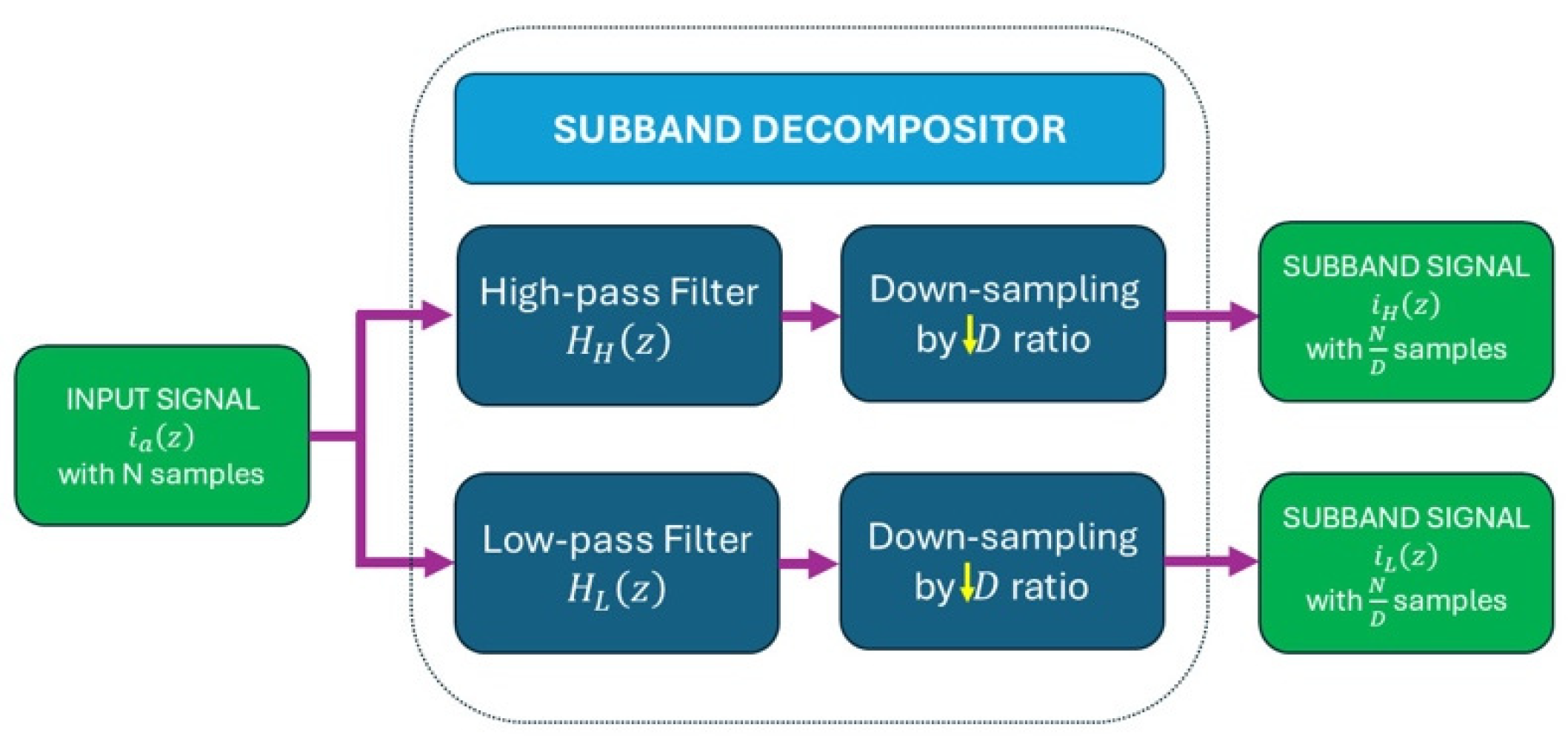
In a subband decomposition, the input signal ia is passed through a pair of quadrature filters: a low-pass filter HL(z) and a high-pass filter HH(z). These filters are designed to satisfy the half-band property. The low-pass filter has a transition band centered at π/2, and approximately half of the impulse response (h(n)) coefficients are zero. This results in computational efficiency. Then, each filtered output is down-sampled by a factor of D = 2. This process results in two subband signals that occupy distinct spectral regions. The process is depicted in Figure 2, which illustrates the block diagram of the subband decomposition structure. The diagram shows the original signal ia entering the system and being split into two branches. The upper path represents the high-pass branch HH(z), followed by down-sampling. The lower path illustrates the low-pass branch HL(z), also followed by down-sampling. The outputs of these branches correspond to the high-frequency and low-frequency components of the signal, respectively. This decomposition ensures that each resulting subband has a reduced number of samples and sampling rate, satisfying the Nyquist criterion. Furthermore, it allows for subsequent processing, such as spectral estimation, to operate at a lower rate while preserving essential signal features.

2.3. Spectral Estimation via Short-Time Minimum Norm

High-resolution spectral estimation methods based on an eigen decomposition are widely used for analyzing non-stationary signals through short-time analysis. One technique in this family is the Short-Time Minimum Norm (STMN) algorithm. It is known for its ability to provide high-resolution estimates that surpass the limitations of conventional Fourier-based methods. The STMN algorithm relies on decomposing the data covariance matrix. Using the spectral properties of this matrix improves the conditioning of the solution. In addition, it helps reduce the impact of noise in the signal space. Let x(n), n = 1, 2, …, N, be the discrete-time stator current signal consisting of a set of real harmonics and embedded in additive white Gaussian noise. The data covariance matrix is defined as follows:
R x x   =   E X   X R m × m
The eigen-decomposition of R x x is given by
R x x = U Λ U H
with U = u 1 , , u m being the orthonormal eigenvectors and Λ = diag λ 1 , , λ m the corresponding eigenvalues arranged in decreasing order. The dominant eigenvectors span the signal space, while the remaining are related to the white Gaussian noise. This decomposition is used to isolate the harmonic components of the lead field matrix G R m × m . Projecting G onto the subspace defined by the dominant eigenvectors can reduce sensitivity to noise and improve numerical stability. The regularized inverse solution is then written as follows:
I ^   =   W   Y ,     with     W = G G G + λ R n 1 ,
where λ is a regularization parameter, and Rn represents an estimate of the noise covariance, often constructed from the eigenvectors corresponding to the smallest eigenvalues of Ry. Eigen-decomposition methods allow a detailed examination of the signal and noise characteristics in multi-frequency component signals. The minimum norm algorithm exploits the orthogonality between the signal and noise subspaces. Specifically, the estimation frequency vector a(f), defined as a f = 0 ,   e j 2 π f , , e j 2 π f M 1 , is orthogonal to all vectors in the noise subspace. Thus, the pseudospectrum is constructed as follows [32]:
S xx f = 1 a H f U n U n H a f ,
where the denominator represents the projection of the estimation frequency vector onto the noise subspace. Singularities in the spectrum function correspond to the harmonic and interharmonic components in the stator current signal. Compared to classical techniques, the minimum norm provides superior spectral resolution with fewer samples. This makes it particularly suitable for the spectral analysis of signals in short-time analyses.

3. Proposed Method

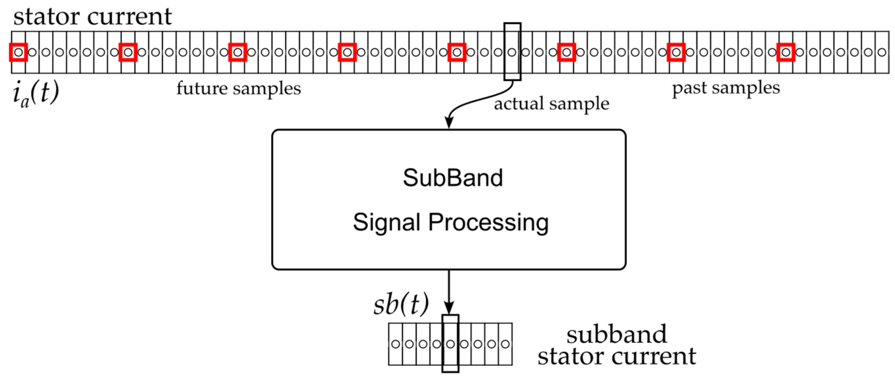
In this section, the proposed method is presented, which employs time-domain signal processing to improve the resolution of speed estimation, addressing the limitations of conventional methods that rely on various sensor measurements and require high computational costs. The input stator current signal ia(t) is composed of a sequence of samples, comprising past, present (actual), and future values, as demonstrated in Figure 3. The output is referred to as sb(t), which contains a frequency subband of ia, in which components are independent for further analysis. At the end, samples of the stator current signal ia(t), which contain the RSH, are chosen for the subband signal processing.
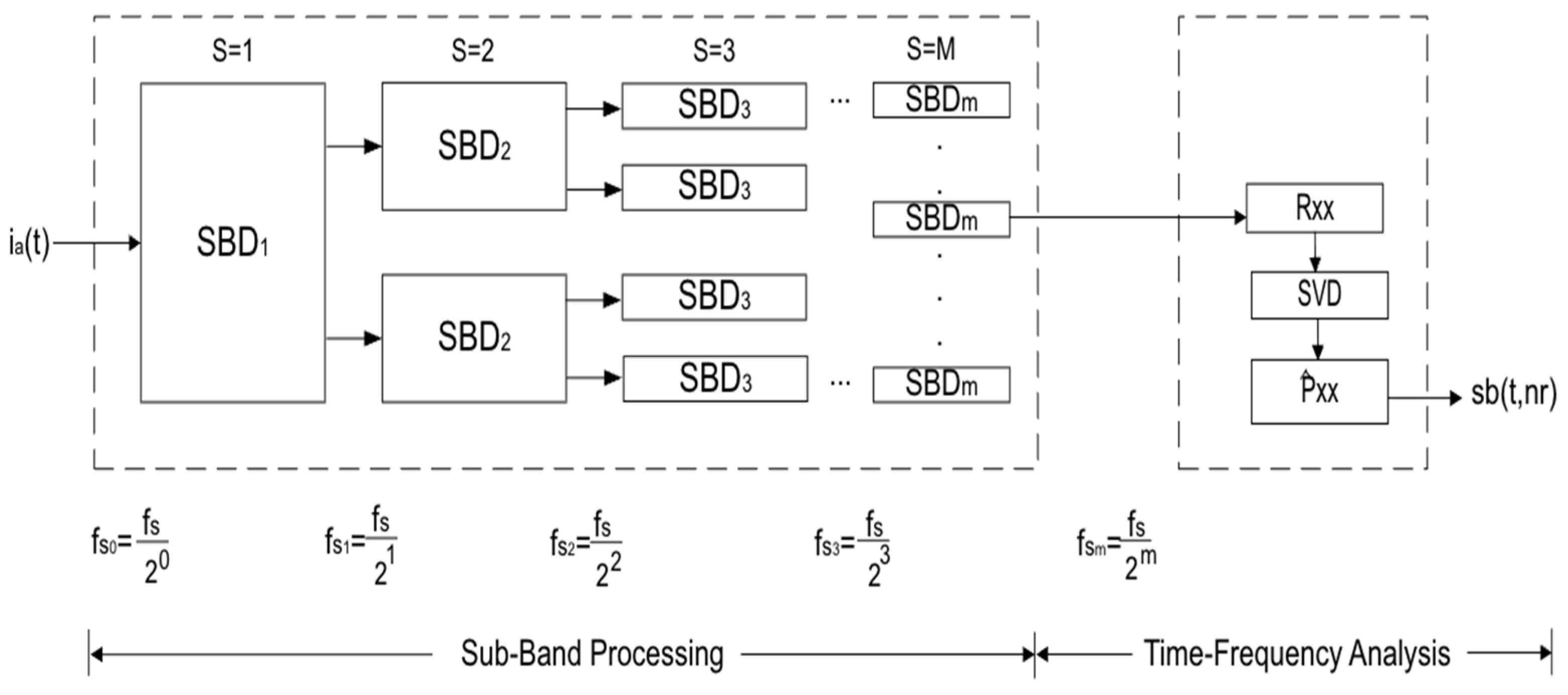
The detailed signal processing method is depicted in Figure 4. The input to the method is the stator current signal, while the output is a time-resolved map of the rotor speed waveform.
The first stage consists of frequency subband division, where the broadband stator current signal is decomposed into multiple narrowband components. The block diagram in Figure 4 represents a general multi-stage subband decomposition structure comprising M stages. This configuration divides the original bandwidth [0, fs/2) into k uniform subbands, each with an identical frequency bandwidth of [0, fs/2)/k Hz. The implementation employs k/2 subband decompositions, as detailed in Section 2.2.2. This multi-stage division enables the selective isolation of spectral regions associated with the rotor speed component, while allowing a reduction in the number of samples to minimize subsequent computation. The selection of the spectral bandwidth for the analysis subband is based on the expected frequency variation in the principal rotor slot harmonic, fsh, across the nominal operating range of the motor. The upper frequency bound of the subband corresponds to the fsh frequency when the motor is operating under no-load conditions, which represents the maximum rotational speed. This value is determined using Equation (3), with s = 0 and the positive harmonic sign. Conversely, the lower limit reflects the fsh frequency when the motor is operating under the maximum rated load, calculated using Equation (3), using the maximum slip provided by the motor manufacturer. This defines the subband where the motor will operate according to industrial reliability standards, ensuring the motor is sized to prevent overload conditions. The difference between these two frequency limits defines the minimum required spectral bandwidth, denoted as sbf, that allows for the accurate tracking of motor speed under all nominal conditions. To ensure that the selected subband encompasses the full operating range, the condition fs/2k > sbf must be satisfied. However, to optimize computational efficiency, the value of fs/2k is chosen to be as close as possible to sbf, minimizing the frequency range.
After subband decomposition, the signal containing the relevant rotor-related spectral components is analyzed using the high-resolution time-frequency technique. The STMN transform is applied to achieve precise spectral estimation. This stage begins with the computation of the autocorrelation matrix Rxx for the subband signal over a short-time window. Singular value decomposition is then performed on Rxx to separate the signal subspace from the noise subspace, effectively discarding the eigenvalues corresponding to noise. Once the signal subspace is identified, the spectral content is constructed for each short-time segment, resulting in a spectral representation of the subband signal. This representation is subsequently transformed into a time-speed distribution (t, nr), which provides a detailed depiction of the dynamic rotor speed behavior over time. This methodology enables fast processing, as the analysis is performed in a short time, and due to the subband decomposition, the matrix decomposition required by the spectral estimator is of a reduced order.

4. Numerical Results

To evaluate the dynamic behavior of the induction motor under load disturbances, time-domain simulations were conducted using MATLAB 2024a software. The system model consists of a 2-pole pair induction motor with 26 rotor slots [12], energized by a 50 Hz voltage source, and mechanically coupled to a second-order load system. The simulations were carried out with a sampling period of 20 µs over a total duration of 10 s. Figure 5 presents the time evolution of the applied load torque, which was simulated in a piecewise manner to introduce abrupt changes and observe their impact on motor dynamics. This disturbance scenario was designed to reflect realistic operational conditions such as the sudden mechanical load increases or decreases that a motor encounters in industrial environments. As shown in Figure 5b, the instantaneous speed reflects imposed disturbances. Each variation in the load torque results in a transient deviation in speed, followed by a gradual return to the steady-state regime. The speed drops and overshoots are consistent with the inertia and damping characteristics of the system.
The simulated stator current signal is analyzed to extract rotor speed information. Figure 6a presents the outcome of a conventional FFT-based analysis. As observed, the spectrum reveals five frequency peaks corresponding to the rotor slot harmonic as described in Equation (3). This multiplicity of peaks introduces ambiguity in estimating both time and speed. A straightforward strategy to mitigate this temporal uncertainty involves reducing the analysis window. However, such a reduction degrades the FFT spectral resolution, obscuring the detection of harmonic peaks. In contrast, Figure 6b illustrates the performance of the proposed method, which addresses these limitations more effectively. This result illustrates the proposed subband t-f analysis method applied to the same stator current signal. The subband analysis enables the identification of non-stationary features induced by torque variations. It is worth noting that the stator current exhibits speed variations due to torque disturbances. The proposed decomposition effectively captures transient spectral densities in the interested frequency range, revealing the instantaneous speed behavior. This analysis demonstrates that the stator current is a viable signal for detecting and characterizing load disturbances.

5. Experimental Test Bench

The test bench described below and shown in Figure 7 was assembled for this study. This laboratory setup comprises a three-phase induction motor, a controllable magnetic powder brake, a current clamp, an encoder, anti-aliasing filters, a data acquisition board, and a laptop PC. Table 2 summarizes the specifications of the tested induction motor.
The motor is loaded with a Lucas-Nülle magnetic powder brake, model SE 2662-5R. The braking power is 1 kW and allows the load torque to be set manually or via a voltage control signal. The following motor signals are captured during the tests: stator current and rotational speed. The stator current is measured with a YHDC current clamp, model SCT013. Its nominal peak current is 5 A, providing a proportional voltage signal in the range of ± 1 V. The D-70054 model from Kübler is the encoder used to record the speed. The encoder is a push–pull type, with an output of 24 V, and offers 1024 PPR. The current signal is passed through an LTC 1564 filter from Linear Technology Corporation (Milpitas, CA, USA). The cutoff frequency was set at 10 kHz. The signals are captured using a National Instruments system (Austin, TX, USA) consisting of the cDAQ-9174 chassis equipped with two modules. One allows the capture of the current (module NI-9215) and the other (module NI-9361) the output of the encoder. This system is connected via a USB port to a laptop PC equipped with Windows 10 OS. Acquisition is performed at a sampling frequency of 20 kHz over a 10 s period. The encoder speed is captured with a specific function provided by Mathworks (Natick, MA, USA). Several trials were performed when the motor, fed from the mains, was running in a stationary state and subjected to load changes that produced variations in its speed.

6. Experimental Results

To validate the proposed methodology, experimental tests were conducted under both stationary and non-stationary operating conditions of the induction motor. The testing scenarios are three representative cases: constant load, instantaneous step load changes, and soft torque step variations. These torque disturbances were selected due to their prevalence in mechanical systems driven by induction motors, where speed variations are primarily induced by variations in the load torque. Time-frequency decompositions were performed using the same short-time parameters to ensure consistency across test cases. The stator current analysis employed the minimum norm algorithm (Section 2.3) with a short-time processing scheme, using 100 samples per window, a 2-sample hop size, and an analysis order of eight. This uniform setup enables a reliable comparative evaluation of the method’s performance across diverse dynamic conditions, reflecting real-world applications. The subband decomposition stage is implemented using nine successive binary divisions (M = 9) of the original signal bandwidth. Starting with a sampling frequency of 100 kHz, this process yields 512 subbands, each with a bandwidth of 97.65 Hz. This frequency range is sufficient to track the complete spectral evolution of the fsh across the full nominal speed range of the motor. The use of binary decomposition (D = 2) not only facilitates isolation but also enables an efficient digital implementation of the down-sampling stages, utilizing the symmetry of the digital structures and minimizing computational processing. The subband selection, while static and motor construction dependent (z and p in Equation (3)), can be recalculated for motors with different rotor slots (z) or pole pair numbers (p) by adjusting the expected frequency limits via Equation (3).

6.1. Motor Speed Estimation Under Constant Load Conditions

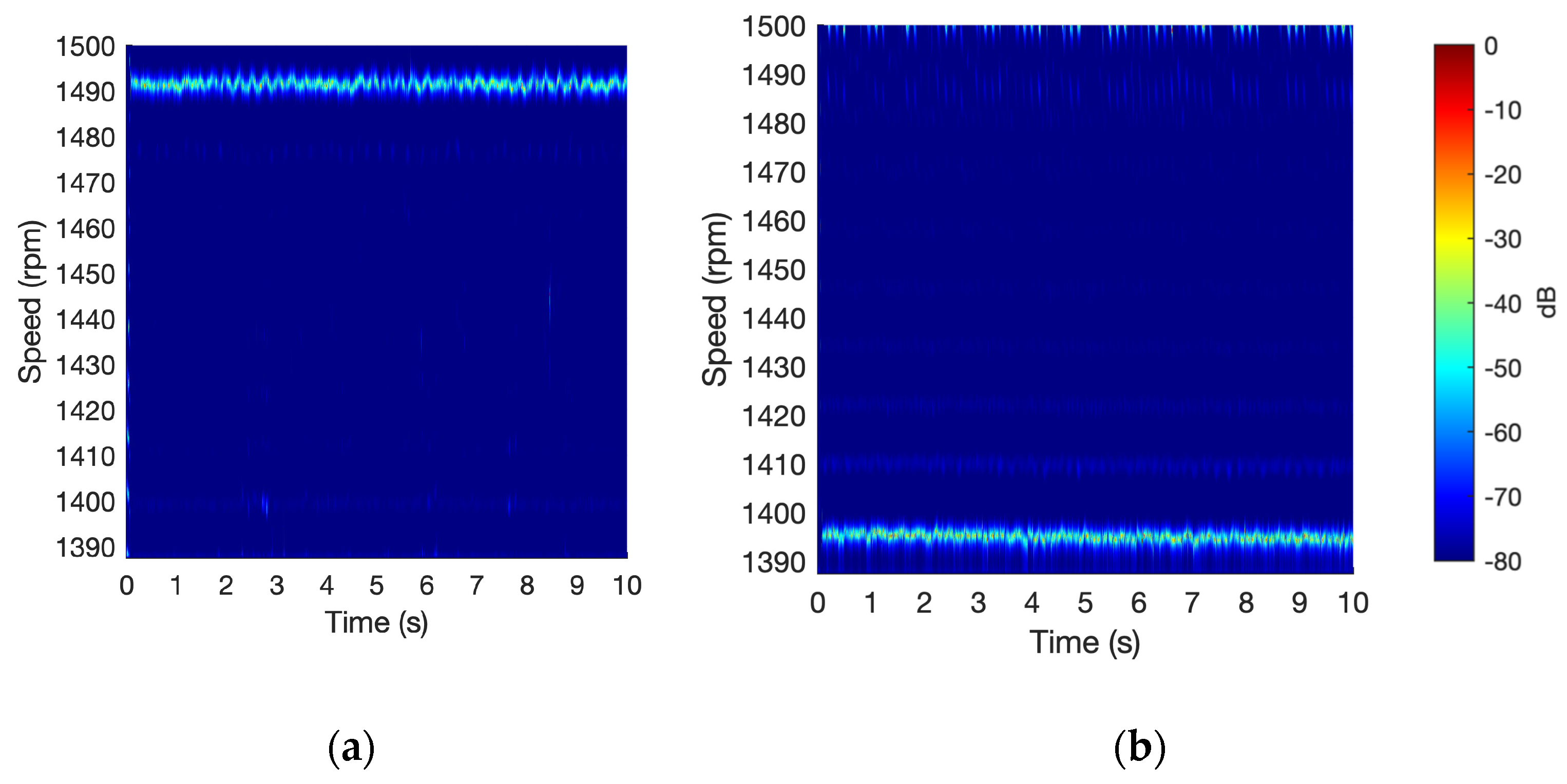
Figure 8a,b illustrates the rotor speed estimation obtained using the proposed method when the induction motor operates under constant load conditions. Figure 8a displays the estimated speed in the case where the motor operates without a mechanical load, consuming a line current of 1.94 A. Under these conditions, the instantaneous speed remains relatively stable over time. The method accurately estimates an average speed of 1491 r.p.m. throughout the duration of the experiment, from 0 to 10 s. Furthermore, the method captures minor speed variations with instantaneous values ranging between 1488 and 1495 r.p.m., thereby highlighting its capability to track small variations under steady-state conditions. Figure 8b presents the speed estimation results when the motor is subjected to a rated load torque, corresponding to a rated line current of 2.2 A. Under this scenario, the motor experiences a high slip level, and the results correctly reflect a reduction in rotor speed due to the increased load. The average speed decreases to 1394 r.p.m., representing a drop of approximately 100 r.p.m. compared to the no-load condition. Despite this reduction, the instantaneous speed remains consistently stable, with small fluctuations of less than 10 r.p.m. throughout the analyzed time (0 to 10 s). Unlike traditional methods, which typically estimate the average motor speed by identifying a peak in the stator current spectrum, the proposed approach can estimate the instantaneous motor speed.
The absence of a load corresponds to the motor’s maximum speed (Figure 8a), while full-load conditions define its minimum operating speed (Figure 8b). This range delineates the nominal operating range of the motor. Introducing a disturbance exceeding this scenario would lead to an overload condition, pushing the machine beyond its rated operational limits as an induction motor. The proposed technique is designed for induction motor operation within the nominal range, as defined by the manufacturer, from no-load to full-load conditions, and is capable of tracking transients that occur within the motor operational band. Additionally, it relies solely on the spectral properties of a single stator line current. These spectral characteristics are not affected by the direction of rotation. Therefore, the functionality is preserved regardless of whether the motor operates in the forward or backward direction.

6.2. Induction Motor Under Load Transients

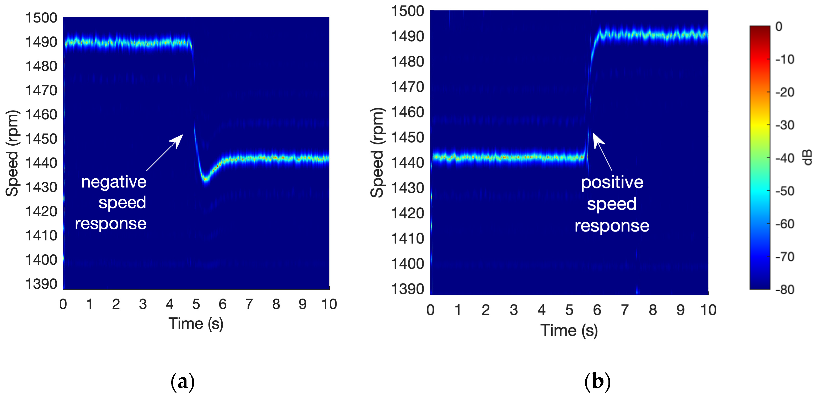
For the purposes of motor control and health condition monitoring, it is critical to evaluate not only the steady-state behavior but also the dynamic performance of instantaneous speed. To this end, experimental tests involving abrupt speed changes were conducted. These changes were induced by sudden variations in the load torque applied through the powder magnetic brake. The corresponding results are depicted in Figure 9. Figure 9a illustrates the rotor speed response to a positive torque step. The motor maintains an average constant speed of approximately 1490 r.p.m. from the start of the test until second 4.8. At this point, a rapid speed drop is observed, reaching 1430 r.p.m. by second 5.2. The proposed method enables an accurate estimation of this speed transition, allowing for the evaluation of a decay time of 0.59 s. The speed quickly settles at a mean value of 1440 r.p.m., approximately 1.25 s after the torque change is applied. Conversely, Figure 9b presents the response to a negative load step, where the torque load is abruptly removed. The proposed methodology estimates a constant speed of 1441 r.p.m. during the first 5.5 s of operation. Following the load removal, a sudden increase in speed is observed. In this case, no overshoot is present in the speed response, and the speed stabilizes within 200 milliseconds, which is faster than in the previous scenario.
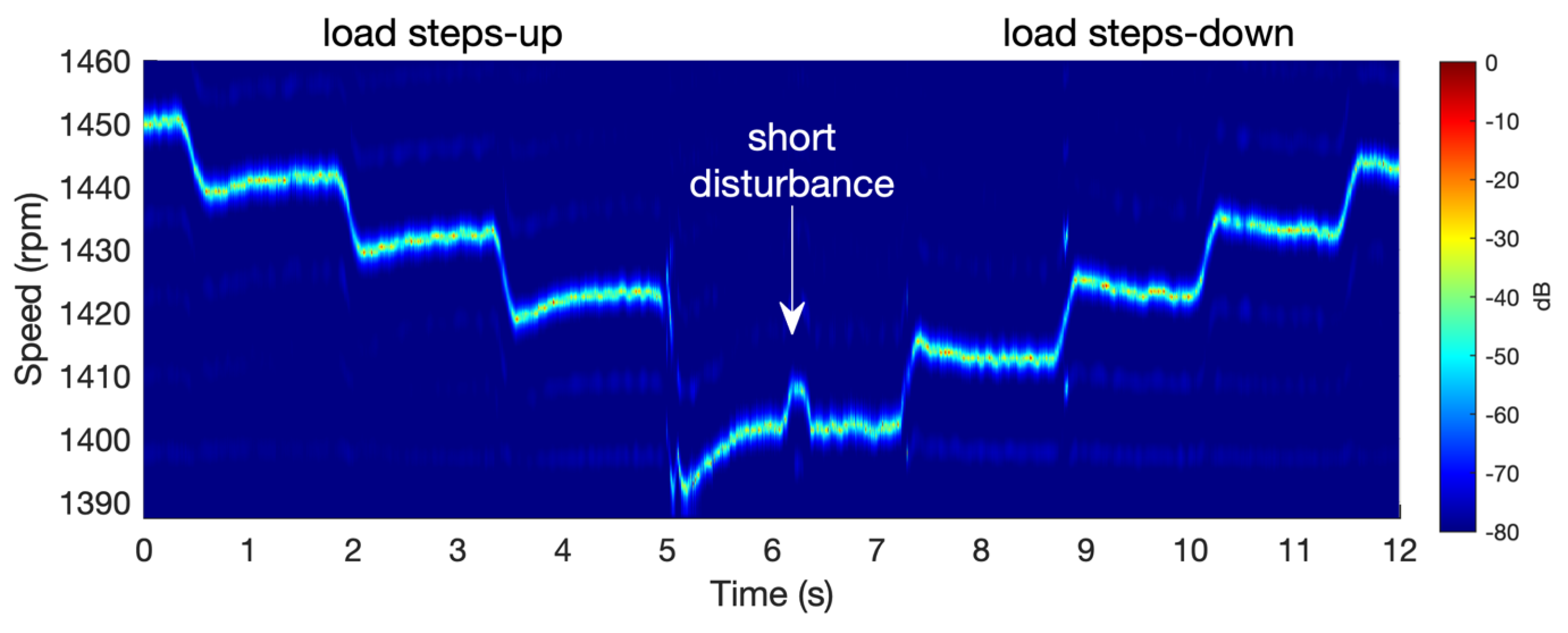
As illustrated in Figure 9, the proposed short-time subband analysis of the stator current successfully captures abrupt changes in the speed. Figure 10 presents the experimental results obtained when the induction motor is subjected to multiple speed and acceleration profiles. In the first part of the experiment, the motor is exposed to load increases that induce a gradual deceleration from 1450 to 1400 rpm. In the second phase, stepwise reductions in load are applied, resulting in a progressive increase in motor speed. The experimental results clearly demonstrate the method’s ability to estimate the actual motor speed, accurately capturing both deceleration and acceleration phases. The observed variations in slope reflect the dynamic response of the motor due to its inherent inertia. Furthermore, at second 6.2, a brief load disturbance is introduced to assess the method’s responsiveness. The method successfully detects this event, capturing the corresponding short-duration variation in motor speed.
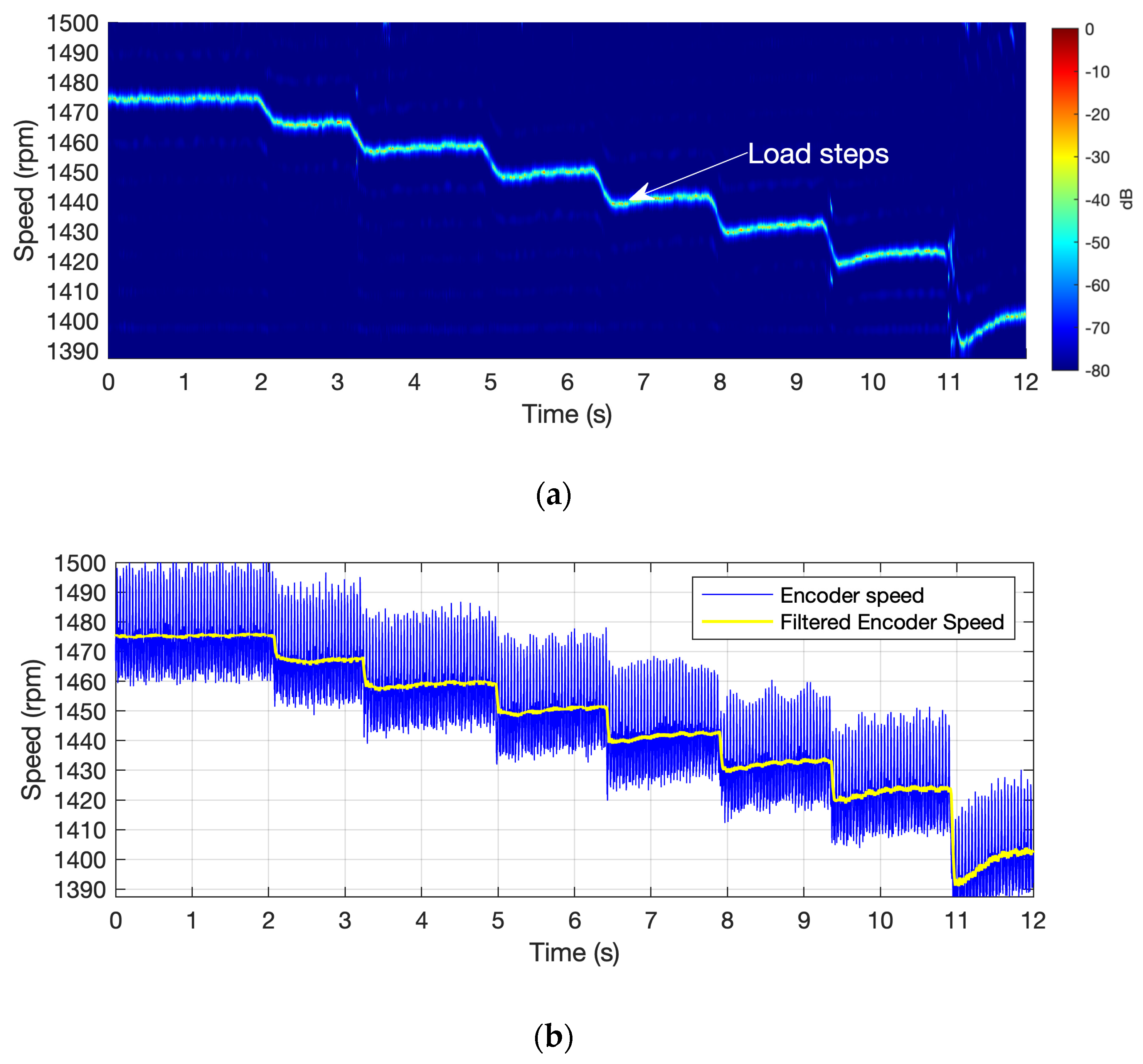
Finally, the motor is subjected to multiple smooth torque variations within a single test, each with a different amplitude level. This test aims to evaluate the system’s response across a wide range of speeds. Figure 11a presents the result obtained using the proposed method, while Figure 11b shows the reference speed signal for comparison. The time-speed analysis, depicted in Figure 11a, clearly identifies seven smooth speed transitions corresponding to the applied torque changes, starting with a 10 r.p.m. speed reduction (torque increment) at second 2 and concluding with a 30 r.p.m. step down at second 11. In contrast, Figure 11b (solid blue line) illustrates the speed signal captured by the optical encoder. This signal exhibits significant high-frequency content, resulting from the wide bandwidth sensitivity provided by the optical sensor (1024 pulses per revolution). However, when the encoder signal is processed using a moving average filter (yellow line), it becomes evident that the proposed method (fsh) closely follows the behavior of the filtered encoder signal. This filtering process is commonly implemented in motor control systems to attenuate noise in feedback signals, thereby highlighting the practical applicability of the proposed approach.
The proposed methodology successfully tracks the rotor speed dynamics under various step changes in both amplitude and duration. The experimental results validate the effectiveness of the method in estimating instantaneous motor speed using only a single-phase current measurement. The tests confirm its reliability under both steady-state and dynamic operating conditions, including scenarios involving rapid and large speed transitions. This method offers the advantage that RSH tracking enables speed estimation without necessitating specific knowledge of motor parameters, such as rotor resistance, leakage inductance, or system inertia.
Table 3 shows a comparison of signal processing using two known techniques and the technique proposed in this paper. The first technique is the Short-Time Fourier Transform (STFT), the standard signal processing technique in the time-frequency domain [33]. The second technique is the Short-Time Multiple Signal Classification (MUSIC) [34], a high-resolution spectral estimator. The third technique compared is the one proposed in this work. All three tools have processed the same signal sampled at a frequency of 100 kHz. Two different analysis times, 5 and 10 s, have also been compared. The test was performed on a PC with Windows 11 Pro, an Intel Core i7-12700K processor, and 64 GB of RAM. The scripts were run on a single core in MATLAB version 2024b. The CPU execution time and maximum RAM were compared.
It can be seen that the signal processing time with STMUSIC is much longer than with STFT and the proposed methodology (approximately four orders of magnitude). The execution time of the proposed method is 1.8 times more than that obtained with STFT. However, the memory used is 7.7 times less for the 5 s signal and 3.8 times less for the 10 s signal. The memory usage of STMUSIC, which required an order of 800 to observe the harmonics in the band of interest, is 700 times greater than that of the proposed methodology.
The subband processing captures only the frequency range containing the oscillation of the principal slot harmonic. This frequency bandwidth segmentation enables the frequency estimator (minimum norm) to operate at a reduced order, specifically using the minimum order λm = 2. As a result, the subspace decomposition achieves a maximum performance by enhancing the projection of orthogonal spaces, while also reducing computational costs through a minimum order. Both the predefined frequency band and the parameters for the short-time analysis are static, thus avoiding the use of adaptive algorithms, which are sensitive to estimator instability and require higher computational effort. It is important to emphasize that the subband preprocessing stage introduces a delay of approximately 60 µs in the generation of an instantaneous speed estimation value. This duration has been minimized through the design of the digital processing architecture and is significantly shorter than the typical dynamic response times of mechanical systems driven by induction motors. Although the proposed preprocessing approach is employed in this work to enhance the performance of a statistical estimator, the underlying signal decomposition remains fully compatible with a broad range of spectral analysis techniques and is well-suited for real-time implementation in industrial motor control systems.

7. Conclusions

This paper presents a subband signal processing methodology for estimating the rotor speed in induction motors functioning within the operational limits defined by the motor manufacturer. By focusing on the spectral region containing the principal rotor slot harmonic and using a high-resolution estimator, the approach enables an accurate, noise-resilient, and instantaneous speed estimation with low computational demand. Unlike FFT-based techniques, it is better suited for dynamic operating situations, capturing instantaneous speed variations instead of average values. The proposed method outperformed STFT and STMUSIC in processing time and memory usage while maintaining a high resolution. Its model-independent nature and low resource requirements make it a promising solution for embedded speed monitoring in industrial applications. The proposed technique is fully scalable, as the motor’s power rating does not affect the spectral content of the line current. The experimental results illustrate a wide range of operational scenarios for the motor under nominal conditions, including the minimum and maximum load, instantaneous load changes, smooth load variations, increasing load steps, and descending load steps. Validation through simulations and experiments confirmed its capability to accurately estimate the rotor speed under those different conditions, demonstrating robustness and practical applicability. Additionally, the technique requires only a single current sensor, simplifying integration and reducing costs. Although the current implementation runs on a personal computer, future work aims to deploy the algorithm onto embedded hardware for real-time processing and to integrate it into motor control devices, such as frequency converters. This will involve testing the algorithm at various setpoint frequencies, including low operating speeds.

Author Contributions

Conceptualization, T.K.A.-S. and T.G.-C.; methodology, T.K.A.-S. and T.G.-C.; software, T.K.A.-S. and T.G.-C.; validation, K.U.-M., O.D.-P. and D.M.-S.; formal analysis, T.K.A.-S. and T.G.-C.; investigation, T.K.A.-S. and K.U.-M.; resources, O.D.-P. and D.M.-S.; data curation, T.K.A.-S. and K.U.-M.; writing—original draft preparation, T.K.A.-S. and T.G.-C.; writing—review and editing, O.D.-P. and D.M.-S.; visualization, T.G.-C.; supervision, O.D.-P. and T.G.-C. All authors have read and agreed to the published version of the manuscript.

Funding

This research received no external funding.

Data Availability Statement

The data that support the findings of this study are available from the corresponding author upon reasonable request.

Conflicts of Interest

The authors declare no conflicts of interest.

Abbreviations

The following abbreviations are used in this manuscript:
EKFExtended Kalman Filter
FFTFast Fourier Transform
IMInduction Motors
PLLPhase Lock Loop
STMNShort Time Minimum Norm
STMUSICShort Time Multiples Signal Classification

References

  1. Khumalo, N.S.; Memane, N.P.; Akuru, U.B. Performance and Safety Improvement of Induction Motors based on Testing and Evaluation Standards. IEEE CES Trans. Electr. Mach. Syst. 2024, 8, 310–318. [Google Scholar] [CrossRef]
  2. Araújo, V.G.d.; Bissiriou, A.O.-S.; Villanueva, J.M.M.; Villarreal, E.R.L.; Salazar, A.O.; Teixeira, R.d.A.; Fonsêca, D.A.d.M. Monitoring and Diagnosing Faults in Induction Motors’ Three-Phase Systems Using NARX Neural Network. Energies 2024, 17, 4609. [Google Scholar] [CrossRef]
  3. Aguayo-Tapia, S.; Avalos-Almazan, G.; Rangel-Magdaleno, J.d.J.; Ramirez-Cortes, J.M. Physical Variable Measurement Techniques for Fault Detection in Electric Motors. Energies 2023, 16, 4780. [Google Scholar] [CrossRef]
  4. Akbar, S.; Vaimann, T.; Asad, B.; Kallaste, A.; Sardar, M.U.; Kudelina, K. State-of-the-Art Techniques for Fault Diagnosis in Electrical Machines: Advancements and Future Directions. Energies 2023, 16, 6345. [Google Scholar] [CrossRef]
  5. Garcia, M.; Panagiotou, P.A.; Antonino-Daviu, J.A.; Gyftakis, K.N. Efficiency Assessment of Induction Motors Operating Under Different Faulty Conditions. IEEE Trans. Ind. Electron. 2019, 66, 8072–8081. [Google Scholar] [CrossRef]
  6. Nandi, S.; Ahmed, S.; Toliyat, H.A.; Bharadwaj, R.M. Selection criteria of induction machines for speed-sensorless drive applications. IEEE Trans. Ind. Appl. 2003, 39, 704–712. [Google Scholar] [CrossRef]
  7. Milić, A.R.; Vukosavić, S.N. Sensorless control of induction motor based on rotors slot harmonics and digital adaptive filters. IEEE Trans. Ind. Appl. 2024, 60, 3950–3963. [Google Scholar] [CrossRef]
  8. Elbarbary, Z.M.S.; Al-Harbi, O.K.; Al-Gahtani, S.F.; Irshad, S.M.; Abdelaziz, A.Y.; Mossa, M.A. Review of speed estimation algorithms for three-phase induction motor. MethodsX 2024, 12, 102546. [Google Scholar] [CrossRef]
  9. Dong, Z.; Sun, Z.; Sun, H.; Wang, W.; Mei, X. A Novel Control Method for Permanent Magnet Synchronous Linear Motor Based on Model Predictive Control and Extended State Observer. Actuators 2024, 13, 34. [Google Scholar] [CrossRef]
  10. Yang, Z.; Qian, C.; Sun, X.; Zhu, Z. Low-speed sensorless control based on improved finite position set-observer for interior permanent magnet synchronous motors. IEEE Trans. Power Electron. 2024, 39, 10921–10933. [Google Scholar] [CrossRef]
  11. Guo, Z.; Li, J.; Yan, M.; Wang, G. Composite speed control based on an improved gain-adaptive super-twisting sliding mode observer for a permanent magnet synchronous motor. Control Eng. Pract. 2025, 157, 106241. [Google Scholar] [CrossRef]
  12. Amin, M.M.; El-Sousy, F.F.; Mohammed, O.A.; Aziz, G.A.A.; Gaber, K. MRAS-based super-twisting sliding-mode estimator combined with block control and DTC of six-phase induction motor for ship propulsion application. IEEE Trans. Ind. Appl. 2021, 57, 6646–6658. [Google Scholar] [CrossRef]
  13. Yildiz, R.; Barut, M.; Zerdali, E. A comprehensive comparison of extended and unscented Kalman filters for speed-sensorless control applications of induction motors. IEEE Trans. Ind. Inform. 2020, 16, 6423–6432. [Google Scholar] [CrossRef]
  14. Garcia-Calva, T.A.; Morinigo-Sotelo, D.; Mwata-Velu, T.; Garcia-Perez, A.; Uribe-Murcia, K. Rotor Speed Estimation for Half-Broken Bar Detection in Induction Motors using Kalman Filtering. IOP Meas. Sci. Technol. 2024, 35, 076115. [Google Scholar] [CrossRef]
  15. Özkurt, G.; Zerdali, E. Design and implementation of hybrid adaptive extended Kalman filter for state estimation of induction motor. IEEE Trans. Instrum. Meas. 2022, 71, 7500212. [Google Scholar] [CrossRef]
  16. Zorgani, Y.A.; Koubaa, Y.; Boussak, M. MRAS state estimator for speed sensorless ISFOC induction motor drives with Luenberger load torque estimation. ISA Trans. 2016, 61, 308–317. [Google Scholar] [CrossRef]
  17. Miloud, I.; Cauet, S.; Etien, E.; Salameh, J.P.; Ungerer, A. Real-time speed estimation for an induction motor: An automated tuning of an extended Kalman filter using voltage–current sensors. Sensors 2024, 24, 1744. [Google Scholar] [CrossRef]
  18. Fu, Y.; Cheng, L.; Yu, J.; Duan, X.; Tian, H. Sideband harmonics identification and application for slip estimation of induction motors based on a self-adaptive wiener filter. IEEE Trans. Instrum. Meas. 2023, 72, 3522512. [Google Scholar] [CrossRef]
  19. Diarra, M.N.; Zhao, X.; Wu, X.; Nketsiah, I.A.; Li, Y.; Zhao, H. Induction Motors Speed Estimation by Rotor Slot Harmonics Frequency Using Zoom Improved Chirp-Z Transform Algorithm. Energies 2022, 15, 7877. [Google Scholar] [CrossRef]
  20. Laadja, K.; Bento, F.; Antunes, H.R.P.; Sahraoui, M.; Cardoso, A.J.M. Speed Estimation of Six-Phase Induction Motors, Using the Rotor Slot Harmonics. Sensors 2022, 22, 8157. [Google Scholar] [CrossRef]
  21. Zhang, Q.; Jiang, T.; Wei, X. Instantaneous speed estimation of induction motor by time-varying sinusoidal mode extraction from stator current. Mech. Syst. Signal Process. 2023, 200, 110608. [Google Scholar] [CrossRef]
  22. Singh, G.; Anil Kumar, T.C.; Naikan, V.N.A. Speed estimation of rotating machinery using generated harmonics. Comput. Electr. Eng. 2018, 72, 420–430. [Google Scholar] [CrossRef]
  23. Dias, C.G.; Silva, L.C.A. Induction Motor Speed Estimation Based on Airgap Flux Measurement Using Hilbert Transform and Fast Fourier Transform. IEEE Sens. J. 2022, 22, 12690–12699. [Google Scholar] [CrossRef]
  24. Keysan, O.; Ertan, H.B. Real-Time Speed and Position Estimation Using Rotor Slot Harmonics. IEEE Trans. Ind. Inform. 2013, 9, 899–908. [Google Scholar] [CrossRef]
  25. Degner, M.W.; Lorenz, R.D. Position estimation in induction machines utilizing rotor bar slot harmonics and carrier frequency signal injection. IEEE Trans. Ind. Appl. 2000, 36, 736–742. [Google Scholar] [CrossRef]
  26. Yu, J.; Zhang, Y.; Zheng, X. An Improved PLL-Based Speed Estimation Method for Induction Motors through Harmonic Separation. Energies 2022, 15, 6626. [Google Scholar] [CrossRef]
  27. Liu, D.; Tsuruta, S. Robust Slot Harmonic Extraction in Varying Speed Operations. In Proceedings of the 2024 International Conference on Electrical Machines (ICEM), Torino, Italy, 1 September 2024. [Google Scholar]
  28. Meira, M.; Bossio, G.R.; Verucchi, C.J.; Ruschetti, C.R.; Bossio, J.M. Speed Estimation During the Starting Transient of Induction Motors. IEEE Trans. Instrum. Meas. 2021, 70, 9000108. [Google Scholar] [CrossRef]
  29. Dias, C.G.; Rodrigues, K.L.; Menegasse, N.C.; Alves, W.A.L.; Silva, L.C.d. Histogram of Oriented Gradients for Rotor Speed Estimation in Three-Phase Induction Motors. IEEE Trans. Instrum. Meas. 2023, 72, 7503811. [Google Scholar] [CrossRef]
  30. Chirindo, M.; Khan, M.A.; Barendse, P. Analysis of Non-Intrusive Rotor Speed Estimation Techniques for Inverter-Fed Induction Motors. IEEE Trans. Energy Convers. 2021, 36, 338–347. [Google Scholar] [CrossRef]
  31. Proakis, J.G.; Manolakis, D.G. Digital Signal Processing: Principles, Algorithms, and Applications, 4th ed.; Pearson Prentice Hall: Upper Saddle River, NJ, USA, 2007. [Google Scholar]
  32. Garcia-Calva, T.A.; Skarmoutsos, G.A.; Morinigo-Sotelo, D.; Mueller, M.; Romero-Troncoso, R.d.J. Demagnetization Monitoring and Identification in PM Generators with Concentrated Windings During Transient Conditions. IEEE Trans. Ind. Appl. 2023, 59, 1510–1518. [Google Scholar]
  33. Houili, M.; Sahraoui, M.; Marques Cardoso, A.J.; Alloui, A. Zero-Sequence Voltage Outperforms MCSA-STFT for a Robust Inter-Turn Short-Circuit Fault Diagnosis in Three-Phase Induction Motors: A Comparative Study. Machines 2025, 13, 501. [Google Scholar] [CrossRef]
  34. Garcia-Calva, T.A.; Morinigo-Sotelo, D.; Garcia-Perez, A.; Camarena-Martinez, D.; Romero-Troncoso, R.d.J. Demodulation Technique for Broken Rotor Bar Detection in Inverter-Fed Induction Motor Under Non-Stationary Conditions. IEEE Trans. Energy Convers. 2019, 34, 1496–1503. [Google Scholar] [CrossRef]
Figure 1. Block diagram of sample rate compressor.
Energies 18 04538 g001
Figure 2. Block diagram of subband decomposition.
Energies 18 04538 g002
Figure 3. Subband decomposition processed in the time domain. Samples marked with red squares illustrate the 8-to-1 sample reduction for a subband decomposition.
Energies 18 04538 g003
Figure 4. Speed estimator structure based on subband signal analysis.
Energies 18 04538 g004
Figure 5. Numerical results for an induction motor under time-varying conditions: (a) load torque; (b) rotor speed.
Energies 18 04538 g005aEnergies 18 04538 g005b
Figure 6. Numerical results for an induction motor under time-varying conditions: (a) FFT-based analysis of the stator current; (b) subband time-frequency analysis of the stator current.
Energies 18 04538 g006
Figure 7. Laboratory test bench: (1) brake, (2) induction motor, (3) current clamp, (4) encoder, (5) anti-aliasing filters, (6) data acquisition system, and (7) laptop PC.
Energies 18 04538 g007
Figure 8. Rotor speed estimation for (a) induction motor under no-load conditions; (b) induction motor under full-load conditions.
Energies 18 04538 g008
Figure 9. Rotor speed estimation for (a) induction motor under positive load step; (b) induction motor under negative load step.
Energies 18 04538 g009
Figure 10. Rotor speed estimation for the induction motor under speed different acceleration profiles.
Energies 18 04538 g010
Figure 11. Experimental results. Load step responses: (a) proposed methodology; (b) 1024 p.p.r. encoder.
Energies 18 04538 g011
Table 1. Comparative analysis of RSH-based speed estimation methods.
Method/Reference Computational Complexity Robustness to NoiseEstimation Accuracy Dynamic Conditions Suitability Key Advantages Main Limitations
Enhanced Chirp-Z Transform [16]Low-MediumModerateHighLimited
  • Improved frequency resolution
  • Lower complexity than full-spectrum FFT
  • Full-band processing
  • Limited to steady-state
FFT-based with Time Evolution Tracking [17]MediumLow-ModerateModerateModerate
  • Tracks spectral component evolution
  • Simple implementation
  • Full-band processing
  • Reduced noise immunity
Adaptive Sinusoidal Mode Decomposition [18]HighModerateHighGood
  • Handles non-stationary behaviors
  • Adaptive to signal changes
  • Complex processing steps
  • High computational burden
Harmonic Enhancement with Vibration Signals [19]HighModerateHighGood
  • Addresses non-stationary conditions
  • Enhanced harmonic detection
  • Requires supplementary sensors
  • Increased system complexity
Signal Demodulation with Hall Sensors [20]Low-MediumGoodModerateLimited
  • Direct measurement approach
  • Simple implementation
  • Requires additional Hall sensors
  • Hardware dependent
Zero-Crossing Detection of RSHs [21]LowLowModeratePoor
  • Very low computational cost
  • Real-time capable
  • Sensitive to noise
  • Limited to steady-state
Injected Carrier Signals [22]MediumGoodHighModerate
  • Controlled signal injection
  • Good noise rejection
  • Requires signal injection hardware
  • May interfere with motor operation
PLL-based Harmonic Separation [23]MediumGoodHighModerate
  • Good tracking performance
  • Established technology
  • PLL tuning required
  • Convergence time issues
Sparse Spectral Analysis with SVD [24]HighExcellentHighExcellent
  • Superior noise robustness
  • Handles high-level speed changes
  • High computational complexity
  • Processing latency
Digital Adaptive Filters + PLL [25]Medium-HighGoodHighGood
  • Low latency
  • Integrated with control loops
  • Complex architecture
  • Parameter tuning required
Multi-Harmonic STFT Monitoring [26]Medium-HighGoodHighGood
  • Motor parameter independent
  • Transient operation capable
  • Full-band processing
  • Multiple harmonic tracking overhead
Histograms of Oriented Gradients [27]MediumModerateGoodGood
  • Time-domain approach
  • High response speed
  • Single-phase measurement
  • High-dimensional feature extraction
  • Training phase required
Table 2. Specifications of the induction motor tested in the laboratory.
Characteristic
ManufacturerSiemens
Motor Model1LA7083-4AA10
Motor TypeThree-phase induction motor
Stator Winding ConnectionStar
Rated Power750 W
Rated Voltage400 V
Rated Frequency50 Hz
Number of Poler Pairs2
Rotor TypeSquirrel cage
Number of Rotor Bars26
Table 3. Comparison of computational burden.
MethodologyAnalysis Time (s)CPU Time (s)Memory Peak (GB)
Short-Time Fourier Transform50.105320.0284
100.110940.0284
Short-Time MUSIC *59873.84652.5085
1017,668.50195.4944
Proposed Methodology
Subband-STMN
50.18760.0037
100.20070.0075
* MUSIC order: 800.
Disclaimer/Publisher’s Note: The statements, opinions and data contained in all publications are solely those of the individual author(s) and contributor(s) and not of MDPI and/or the editor(s). MDPI and/or the editor(s) disclaim responsibility for any injury to people or property resulting from any ideas, methods, instructions or products referred to in the content.