Article

Research on Thermal Performance of the Microchannel with Internal Cavities Under Al2O3-Water Nanofluid

1
School of Mechanical Engineering and Mechanics, Xiangtan University, Xiangtan 411105, China
2
College of Mechanical and Electrical Engineering, Central South University, Changsha 410083, China
*
Authors to whom correspondence should be addressed.
Energies 2025, 18(16), 4419; https://doi.org/10.3390/en18164419
Submission received: 11 June 2025 / Revised: 4 August 2025 / Accepted: 8 August 2025 / Published: 19 August 2025

Abstract

As the demand for efficient heat dissipation in information devices continues to escalate, the heat flux of integrated packaging devices is poised to reach 100 W/cm2 universally, rendering microchannel liquid cooling technology a pivotal solution in thermal management. In this work, the microchannel heat sink with spoiler cavities, optimized via field synergy principle, was integrated into the high-power electronics, and its flow and heat transfer performance were experimentally investigated using Al2O3-water nanofluid. The results show that the experimental and simulation results of the optimized microchannel heat sink integrated with IGBT devices are in good agreement. With structural optimization combined with an appropriate volume fraction of nanofluid, the microchannel heat sink exhibited significantly better heat dissipation performance than that of rectangular heat sinks under a heat flux of 100 W/cm2. Furthermore, when the volumetric flow rate exceeded 0.6 mL/s, the heat transfer performance was improved by 38% compared to the rectangular microchannel heat sink with 1% volume fraction of Al2O3-water nanofluid.

1. Introduction

As integrated circuits (ICs) continue to advance toward miniaturization and higher levels of integration, the power density and heat flux density of chip devices are steadily increasing. Consequently, thermal management has become a critical technical bottleneck that impedes the development of high-end devices [1,2].
To ensure the safe and reliable operation of such systems, microchannel heat sinks combined with nanofluid cooling technology have emerged as a leading solution, particularly in fields such as ultra-high voltage (UHV) power grids; high-frequency, high-power, light-emitting diodes; and high-power rail transit [3,4,5,6,7,8]. Therefore, a comprehensive understanding and precise characterization of the flow and heat transfer properties of newly designed microchannel heat sinks integrated into high-power electronics is essential. Such insights will provide valuable references for practical engineering applications.
Since Tuckerman and Pease [9] first proposed the microchannel heat sink (MCHS) cooling technology for microelectronic devices in 1981, the microchannel heat sink has gradually become a focal point of interest for heat transfer researchers [10]. Since then, extensive investigations have been conducted to optimize the performance of the microchannel, including studies on geometrical optimization [11,12], double-layer microchannels [13,14], and wavy microchannels [15,16]. Notably, among the various factors contributing to the enhancement of microchannel heat transfer performance, designing novel microchannel configurations remains a key area of ongoing research [17]. In particular, optimizing microchannel geometry is the most widely adopted approach for improving heat transfer efficiency. For instance, Feng et al. proposed a microchannel with circular pin fins to enhance heat transfer by reducing local wall temperature deterioration [18]. Foong et al. introduced uniform internal fins on all internal walls of a square microchannel to improve heat transfer efficiency [19]. Xie et al. conducted numerical investigations to determine the optimal positioning of vertical bifurcations within the microchannel, aiming to enhance their heat transfer performance [20]. Chakraborty et al. analyzed the heat transfer characteristics of the microchannel incorporating holes and pillars, identifying an optimal arrangement that improves heat transfer performance without increasing pumping power [21]. Park et al. analyzed the influence of temperature and flow field changes on the heat transfer performance of microchannels [22]. Xin et al. numerically studied the effects of five different arrangements of manifold microchannel heat sinks on flow and heat transfer performance and proposed guiding suggestions to optimize the manifold microchannels [23]. In addition, Xia et al. attributed heat transfer enhancement in the microchannel with uniform fan-shaped cavities and internal ribs to increased heat transfer surface area, periodic redevelopment of the boundary layer, and the jet and throttling effects [24,25]. Zhai et al. demonstrated that optimizing the internal structure of the microchannel could enhance heat transfer based on the field synergy principle and the entropy generation theory [26,27]. Bi et al. numerically analyzed the convective heat transfer mechanisms in the microchannel with varying internal configurations and proposed that the synergy angle is a key parameter for understanding the heat transfer enhancement [28].
On the other hand, to meet the growing heat dissipation demands of high-heat-flux devices, in addition to optimizing the structure of the MCHS for enhanced thermal performance, many researchers have proposed the use of nanofluids, a mixture of nanoparticles suspended in a base fluid, such as water or ethyl alcohol, to improve heat exchange efficiency. Nanofluids, first introduced by Choi et al. in 1995 [29], are regarded as a promising approach for enhancing thermal performance, attracting significant research interest in this domain. Subsequently, Li and Xuan conducted experiments demonstrating the heat transfer enhancement characteristics of nanofluids and proposing two methods for deriving thermal conductivity correlations of the nanofluids [30,31]. Further investigations by Ho et al. explored the forced convective cooling performance of microchannels using Al2O3-water nanofluids, revealing that nanofluids exhibit a significantly higher average heat transfer coefficient compared to pure water [32,33]. Wang et al. performed a reverse geometry optimization to enhance nanofluid heat transfer performance in the microchannel, optimizing the geometry structure under various constraints [34,35]. Additionally, Bianco et al. analyzed the heat transfer performance of Al2O3-water nanofluids within two- and three-dimensional models of an asymmetrically heated channel, applied to solar panels, demonstrating that nanofluids have the potential to improve heat dissipation in PV/T panels [36,37]. Marseglia et al. explored the heat transfer enhancement potential of nanofluid in microchannels under different two-phase flow patterns [38]. Recently, nanofluids have gained increasing recognition as a promising working fluid for heat dissipation applications [39,40,41,42]. For example, Wang et al. analyzed the effective thermal management of electronic devices based on microchannel heat sink and nanofluid [43]. Hamida et al. carried out extensive and in-depth studies on the effective thermal management of LED devices from perspectives such as hybrid nanofluids [44], the electrical effects of nanofluids [45], and nanofluids combined with new fin structures [46]. These studies have provided important theoretical and practical reference values for solving the heat dissipation issues of LEDs. While nanofluids enhance heat transfer performance, they also induce an additional pressure drop due to their increased viscosity. Thus, the feasibility of nanofluids for engineering applications requires further investigation. Consequently, experimental studies on the use of nanofluids in microchannel heat sinks with internal cavities are essential to improving heat dissipation performance prior to their practical implementation.
In summary, the heat dissipation capacity of microchannel heat sinks can be significantly improved by optimizing their internal structures. However, there are still several challenges requiring further investigations for the practical applications of MCHS. The most important and urgent problems are the lack of experimental data, which limits the availability of MCHS. The heat transfer and flow characteristics of a novel microchannel heat sink design must be thoroughly evaluated through extensive testing. Thus, conducting experimental research on the microchannel heat sink is crucial prior to its implementation in real-world applications.
In this work, the heat dissipation performance of the microchannel is further investigated, building upon the microchannel with internal spoiler cavities that was optimized based on the field synergy principle. The flow and heat transfer characteristics of this novel microchannel, utilizing Al2O3-water nanofluid under laminar flow conditions, are analyzed through both numerical simulation and experimental methods. Additionally, to facilitate the practical application of this novel microchannel, experimental research has been conducted to assess the heat dissipation performance of an insulated gate bipolar transistor (IGBT) module integrated with the microchannel, using Al2O3-water nanofluid as the working fluid. Detailed discussions of MCHS are provided on temperature distribution, pressure drop, Nusselt number, overall heat transfer performance, and measurement deviation error metrics.

2. Experimental Methodology

2.1. Geometric Model Establishment

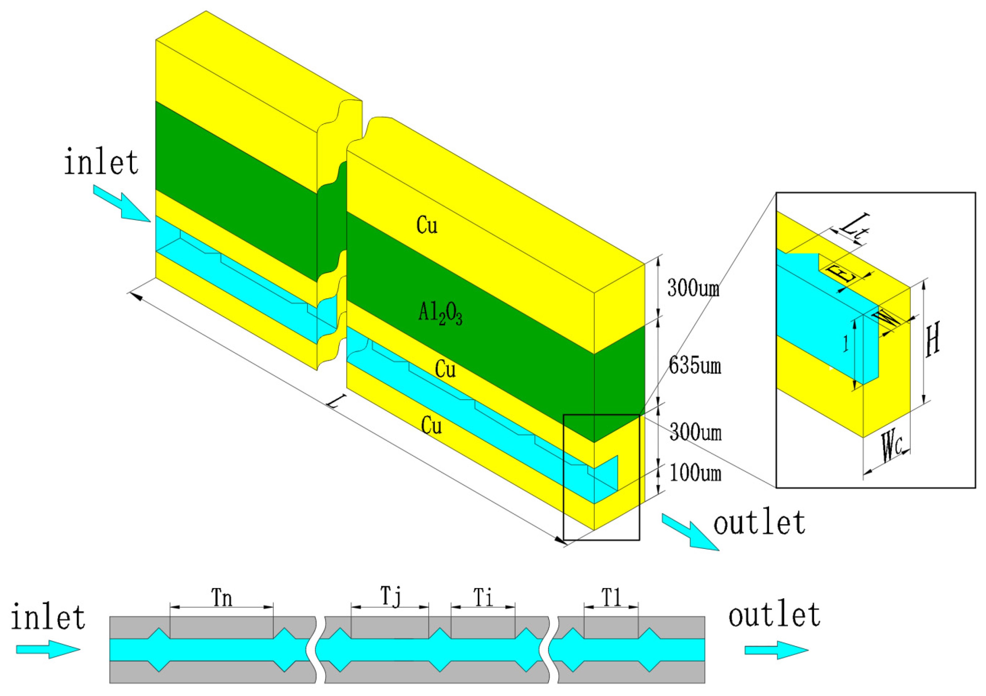
With the advancement of information technology, effective heat dissipation has increasingly become a critical technical challenge, limiting the development of high-performance devices. Traditional heat dissipation methods for integrated circuit (IC) modules typically involve external heat sinks assembled onto the package structure. However, the internal heat generated by the chip must pass through multiple interfaces, leading to significant thermal resistance and increasing the risk of thermal failure. To address the continually evolving heat dissipation demands of high-performance devices, microchannel liquid cooling has emerged as a key technological solution. Focusing on the heat dissipation of high-power insulated gate bipolar transistor (IGBT) modules, a corresponding microchannel heat sink structure was designed, and its heat transfer performance was numerically and experimentally investigated. The geometric structure of the integrated MCHS within the IGBT module is depicted in Figure 1. In addition, the heat dissipation performance of a single chip integrated with the microchannel was selected for both experimental and numerical investigations, as shown in the red dashed box in Figure 1.
The structure diagram of the microchannel heat sink for a single unit is presented in Figure 2. The arrangement of the internal spoiler cavities within the microchannel structure is derived from [47], which was optimized based on the field synergy principle proposed by Guo et al. [48,49,50]. The detailed geometric parameters of the microchannel are as follows: total length L = 10 mm, total height H = 350 μm, half of the total width Wc = 150 μm, channel height H1 = 200 μm, half of the channel width W = 50 μm, cavity height E = 50 μm, cavity length Lt = 160 μm, and number of channels Ns = 33.
The microchannel length parameters of T1, Ti, Tj, and Ln are the distances of the first segment, the i-th segment, the j-th segment, and the n-th segment adjacent cavities counted from the outlet, respectively. The materials of each layer of the integrated MCHS are shown in Figure 2, and the Al2O3-water nanofluid was chosen as the coolant.

2.2. Microchannel Manufacturing and Nanofluids Preparation

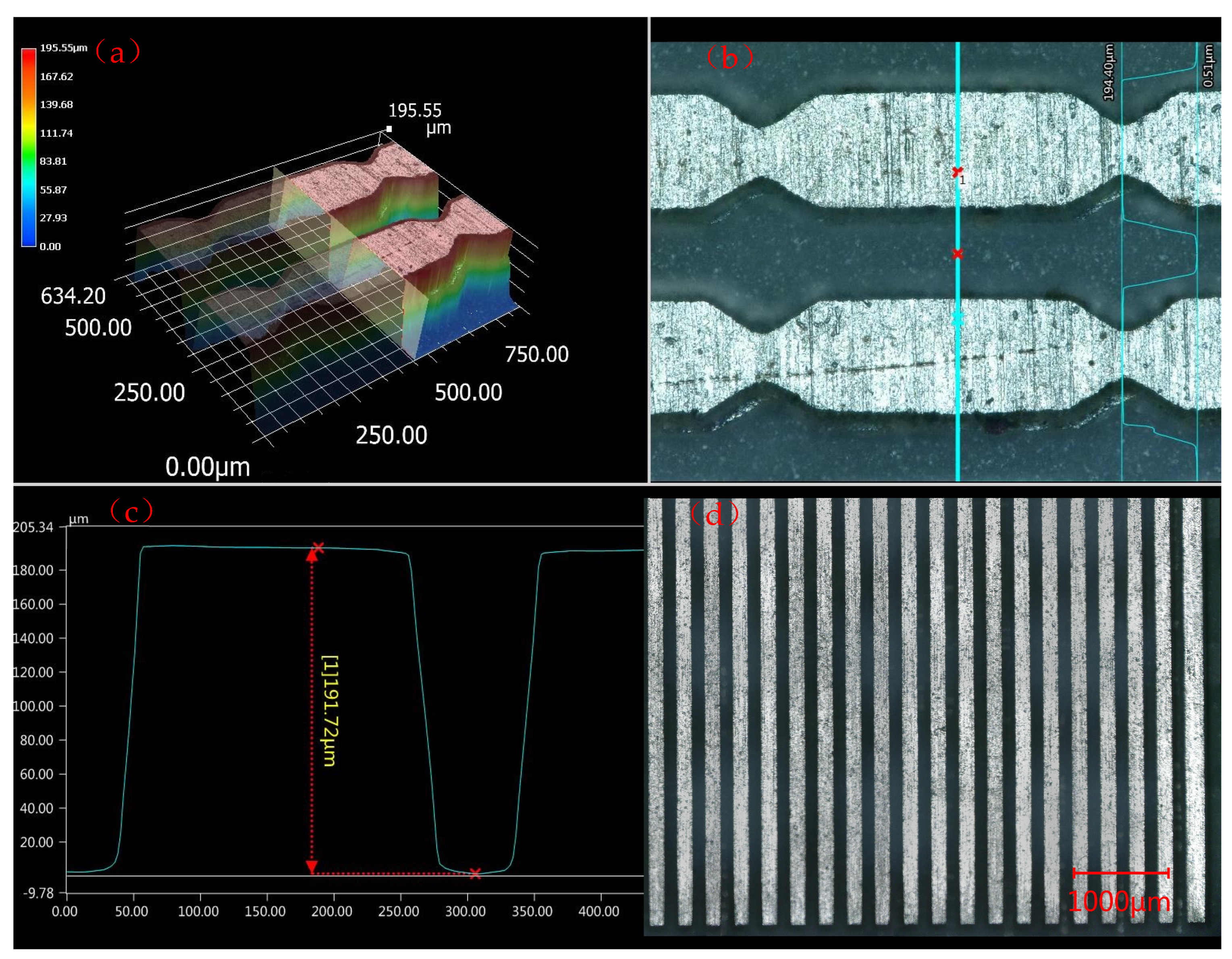
In the experiment, two critical aspects of the thermal performance evaluation for the MCHS are the fabrication of the microchannel in the test section and the preparation of the Al2O3-water nanofluid. For the microchannel fabrication, the copper layer of the Direct Bonded Copper (DBC) substrate in the IGBT module was utilized to fabricate the microchannel through etching and bonding processes. Then, the morphology and structure of the processed microchannels were characterized by a three-dimensional super-depth microscope of type VHX-5000 from KEYENCE Company, Osaka, Japan. The topographies of the processed microchannel samples under the ultra-depth-of-field three-dimensional microscopy system are shown in Figure 3.
For the preparation of nanofluids, alumina (Al2O3) nanoparticles with an average particle size of 36 nm and a purity of 99.9% were selected, consistent with the particle size used in previous studies. These nanoparticles were sourced from Xuancheng Jingrui New Materials Co., Ltd., Xuancheng, Anhui, China. A two-step method was employed to synthesize the nanofluids via mixing, stirring, and ultrasonic vibration, ensuring that the nanofluid remained in a stirred state prior to use in the experiment. The volume fractions of the prepared nanoparticles were 0.1%, 0.5%, and 1%. The density and specific heat of the nanofluid were predicted using the classical mixing model [51]; the specific formulas are described in the following. The viscosity of the nanofluid was measured using a Physica MCR 301 rheometer, and its thermal conductivity was measured with a DRE-III multifunctional rapid thermal conductivity meter. The thermal properties of the nanofluids obtained at room temperature of 25 °C are shown in Table 1. Here, regarding the stability issue of nanofluids, to ensure the accuracy and reliability of experimental results, the experiment requires that the experiment be completed within 30 min after the nanofluid is prepared.

2.3. Testing Systems Setup

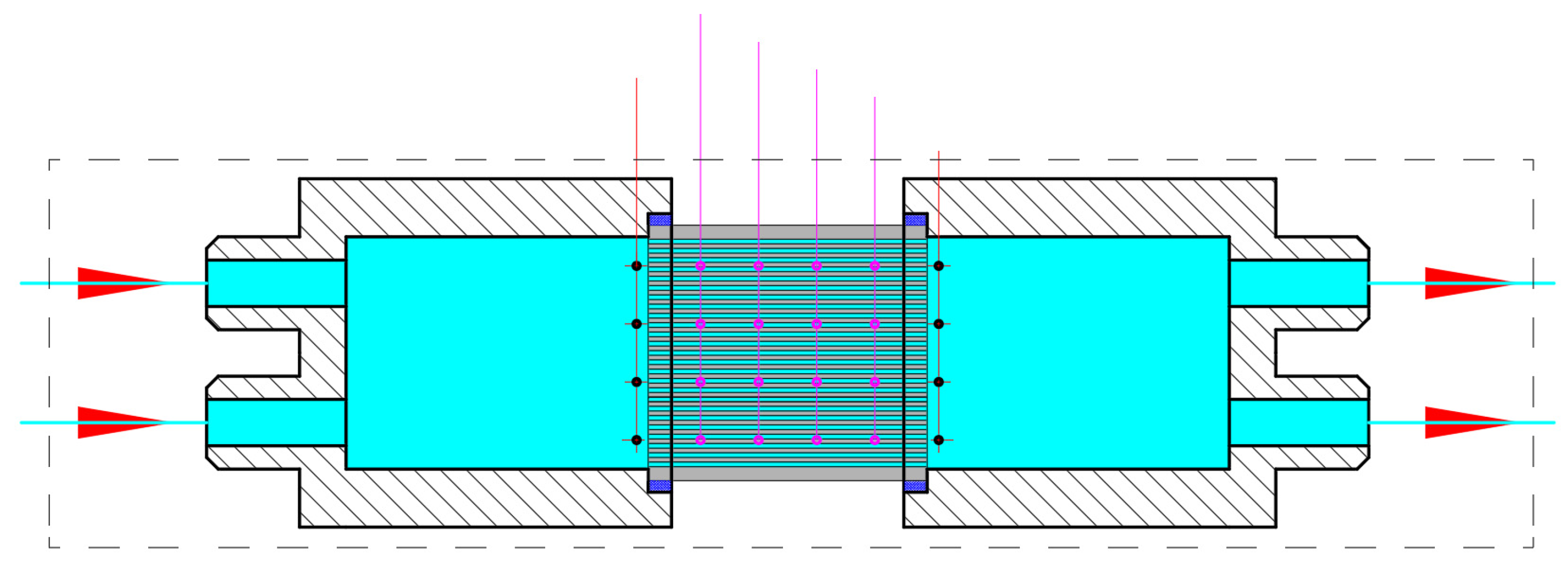
To accurately and reliably test the flow and heat transfer characteristics of the microchannel heat sink, the pumping power, flow rate, and constant heating power were precisely controlled during the experiment. The microchannel flow and heat transfer test platform primarily consists of three components: the water circuit circulation system, the heat transfer parameter measurement system, and the constant power heating system. A process and instrumentation diagram for the flow and thermal testing system is presented in Figure 4.
The experimental system setup for flow and heat transfer testing was subject to the following limitations: the adjustment heat flux range was 0–800 w/cm2; the measurement temperature range of the thermocouple was −40 to 250 °C; the maximum pressure drop provided by the pump was 10 MPa; the flow range could be adjusted between 0–10 L/min; and the size of the test chip ranged from 1 to 5 cm2. The heat source was supplied by a thermal resistance rod, providing a controllable heat flux density. Deionized water and Al2O3-water nanofluid were used as the working fluids. The precision of some important experimental equipment in the experimental system are detailed in Table 2.
Based on the aforementioned experimental test system, the primary measured parameters included the pressure drop between the fluid inlet and outlet, the ambient temperature, the temperature of the inlet and outlet fluid, and the temperature distribution of the heating surface of the microchannel heat sink. According to the measurement requirements of the flow and heat transfer parameters of the microchannel, the location points of the temperature and flow measurement area in the experimental test section are shown in Figure 5.

3. Numerical Simulation

The heat dissipation performances of the selected microchannel heat sink in the IGBT module were analyzed by establishing a three-dimensional conjugate heat transfer model. In this work, the CFD software (Fluent 19.0) was used to calculate the conjugate heat transfer model. For mesh generation, a structured mesh was adopted, and mesh independence verification was performed, including three mesh sizes: Mesh I (65 × 65 × 610), Mesh II (75 × 80 × 690), and Mesh III (85 × 95 × 770). The calculation errors of the three meshes were all within 5%. To save computational resources, Mesh II was finally selected for the calculation. During the calculation process, the model was subject to the following assumptions and limitations: the fluid flow and heat transfer were considered to be in steady-state; the flow was considered incompressible and laminar; viscous dissipation and interface contact thermal resistance were neglected; and the thermal properties of the heat sink materials were considered to be temperature-independent.
For nanofluids or other mixtures [52], the models selected in numerical simulations vary depending on the research objects. Specifically, for nanofluids, the commonly used models include the homogeneous model and the mixture model, which involve the issue of single-phase flow versus two-phase flow. In this work, the single-phase homogeneous model was adopted [53]. The governing equations are shown in what follows.
Continuity equation:
u x + v y + w z = 0
where u, v, w are the velocity components of in x, y, z direction, respectively.
Momentum equation:
ρ f u u x + v u y + w u z = μ f 2 u x 2 + 2 u y 2 + 2 u z 2 P x
ρ f u v x + v v y + w v z = μ f 2 v x 2 + 2 v y 2 + 2 v z 2 P y + ρ f g
ρ f u w x + v w y + w w z = μ f 2 w x 2 + 2 w y 2 + 2 w z 2 P z
where ρ f and μ f are the density and dynamic viscosity of working fluid, P is the pressure, and g is the gravity.
Energy equation in the fluid domain:
ρ f c p f u T x + v T y + w T z = k f 2 T x 2 + 2 T y 2 + 2 T z 2
Energy equation in the solid domain:
k s 2 T x 2 + 2 T y 2 + 2 T z 2 = 0
where c p f , k f , and k s are the specific heat, thermal conductivity of working fluid, and thermal conductivity of the solid, respectively.
In order to ensure the accuracy and reliability of the simulation, a traditional rectangular microchannel and a microchannel with internal cavities were used for verification in our previous work [47]. In addition, to ensure that the numerical simulation aligns with the fundamental conditions of the experiment, a constant heat flux boundary condition was applied to the top surface of the heat sink, while symmetric boundary conditions were imposed on the lateral planes. A uniform velocity u i n with varying values and a constant inlet temperature of Tin = 293 K were applied at the inlet of the microchannel. The thermal conductivity, specific heat, and density of each layer used in the numerical simulation are defined as follows:
Cu: k C u = 401   W / m · K , c p , C u = 390   J / ( k g · K ) , and ρ s = 8950   k g / m 3 , respectively.
Al2O3: k A l 2 O 3 = 40   W / m · K , c p , A l 2 O 3 = 765   J / ( k g · K ) , and ρ A l 2 O 3 = 3970   k g / m 3 , respectively.
The heat flux at the top surface is qw = 100 W/cm2. The detailed boundary conditions are as follows:
At the inlet:  u = u i n , v = 0, w = 0, Tin = 293 K.
At the outlet: p = pout =1 atm.
At the fluid–solid interfaces: u = 0 , v = 0, w = 0; T s = T f ; k s T s n = k f T f n .
At the top surface:  q w = k s T s z = 100 W/cm2.
For the Al2O3-water nanofluid, the thermal physical properties are primarily dependent on temperature. The effective density, specific heat, thermal conductivity, and viscosity of the nanofluid were obtained based on the previous research results [54].
Under a heat flux of 100 W/cm2, and considering the maximum operating temperature of Si chips (125 °C), this work investigated the flow and heat transfer performance of microchannel heat sinks under laminar flow conditions, with the flow rate of the fluid working medium specified in the range of 0.2–1.2 mL/min.

4. Discussion

4.1. Data Processing and Thermal Balance Analysis

The scientific processing of experimental data is crucial for evaluating the validity of observed experimental phenomena and uncovering the underlying mechanisms. The data obtained from the tests were processed as follows.
The mass flow of the working fluid is calculated as
m ˙ = q m · ρ f
where qm is the volumetric flow rate of the working fluid (m3/s). The average flow velocity of the working fluid in the channel is expressed as
u = q v / ( N s · A c )
where NS is the number of microchannel, and AC is the cross-sectional area of a single microchannel (m2).
To measure the temperature on the top surface of the microchannel heat sink, four thermocouples were evenly distributed to record temperature values at both the inlet and outlet. The overall surface temperature was determined by averaging these recorded values. The average temperature of the top surface heat sink is calculated as
T a v e = i = 1 4 ( T e n h i + T o u t h i ) / 4
where Tenhi is the temperature measurement point at the inlet section on the top surface of the heat sink, and Touthi is the temperature measurement point at the outlet section on the top surface of the heat sink. Here, the average temperature of the working fluid is
T = 1 2 ( T i n + T o u t )
where Tin is the average inlet temperature, and Tout is the average outlet temperature.
During the test, the flow rate, pressure drop, and temperature at each measurement point were allowed to stabilize before recording the data for each point at least three times. Under steady-state conditions, the heat absorbed by the working fluid in the microchannel is equal to the heat gained due to the temperature rise of the working fluid, and its calculation relationship is expressed as
Q f l u i d = c p f m ˙ ( T o u t T i n )
where cpf is the specific heat of the working fluid (J/kg °C).
The calculation relation for the convective heat transfer coefficient between the nanofluids in the microchannel and the solid wall surface of the microchannel heat sink is expressed as follows:
h = Q f u l i d A · T m
where h represents the convective heat transfer coefficient, A is the effective contact area that the solid wall inside the microchannel contact with the working fluid, ∆Tm is the logarithmic average temperature between the wall of the microchannel and the working fluid, and its calculation formula is
T m = T o u t T i n l n ( T w ¯ T i n T w ¯ T o u t )
where T w ¯ is the average temperature of the inner wall of the microchannel.
In addition, the Nu number of flow heat exchange between the inner wall of the microchannel and the working fluid can be calculated as
N u = h · D h k f
where Dh is the hydraulic diameter of the microchannel, and kf is the thermal conductivity of the working fluid.
To ensure the reliability of the experimental data, the accuracy of both the experimental apparatus and the collected data was verified through heat balance calculation within the constructed microchannel flow and heat transfer test system. The consistency between the heating power of the microchannel heat sink and the heat absorbed by the fluid was assessed based on the thermal balance deviation ε, which is calculated using the following thermal balance deviation formula:
ε = Q u i Q f l u i d 0.5 ( Q u i + Q f l u i d )
where Qui is the constant heat power of external heating, and its value is Qui = UI; U is the total voltage value, and I is the total current value.
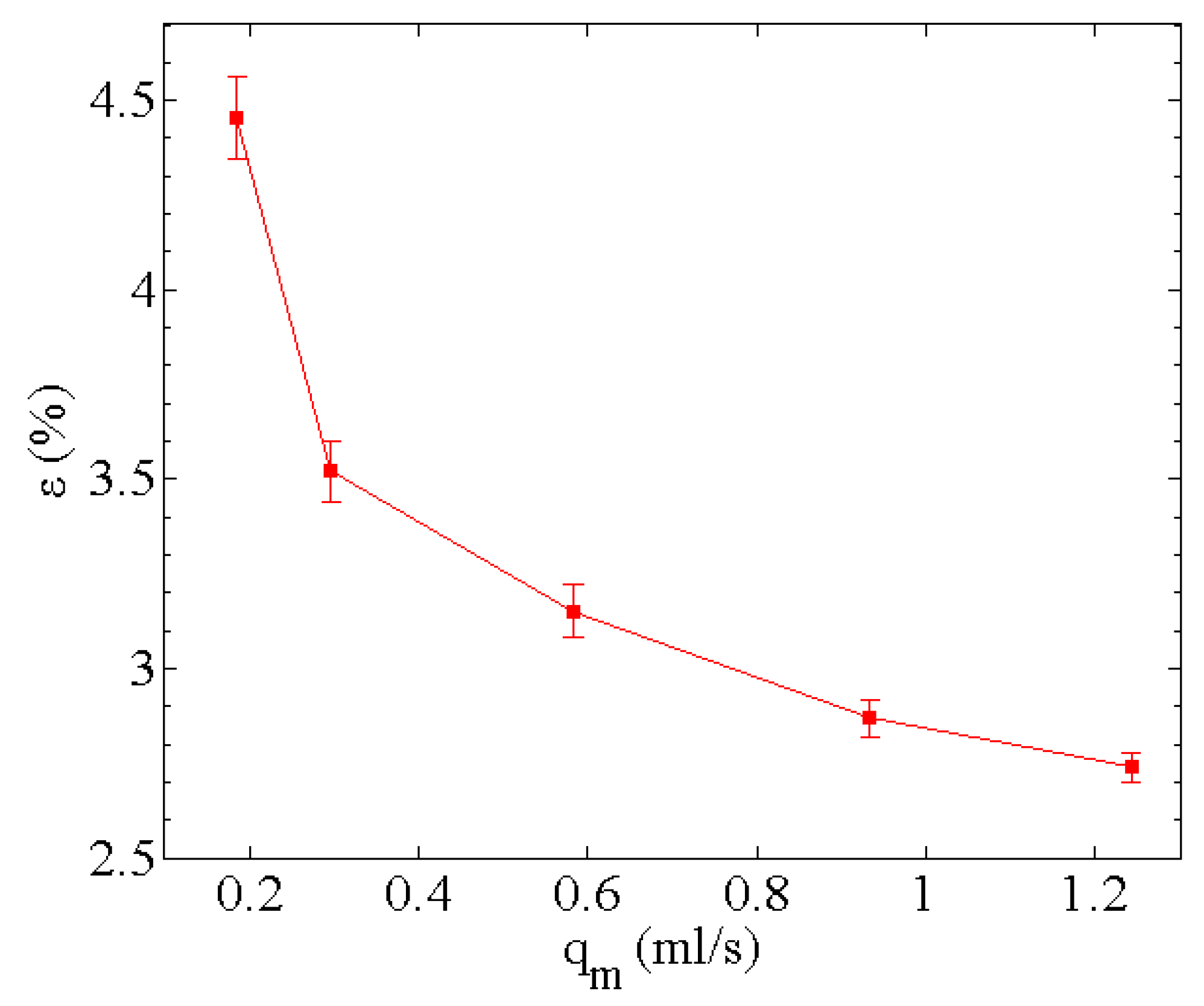
The thermal balance deviation calculated according to the aforementioned formula is shown in Figure 6. It is observed that the thermal balance deviation decreased as the flow rate increased. The maximum thermal balance deviation obtained from experimental measurements remained within 5%. Moreover, when the flow rate reached 1 mL/s, the thermal balance deviation was reduced to below 3%. Analysis of the thermal balance deviation within the experimental system indicates that both the measurement accuracy of the experimental test system and the reliability of the experimental data satisfy the experimental requirements.

4.2. The Flow and Heat Transfer Characteristics Analysis

Based on the above-mentioned test system error analysis, further verification was required to assess the consistency between the measured values from the microchannel test and the simulation results. In addition, to verify the reliability of the flow and heat transfer characteristics in the microchannel, the theoretical value of pressure drops in the microchannel is calculated using the empirical prediction formula proposed by Kandlikar et al. [55], and the relevant pressure drop expirical relationship is as follows:
P = 2 ( f R e ) μ f u L D h + K ( ) ρ u 2 2
f R e = 24 ( 1 1.3553 α + 1.9467 α 2 1.7012 α 3 + 0.9564 α 4 0.2537 α 5 )
K = 0.6796 + 1.2197 α + 3.3089 α 2 9.5921 α 3 + 8.9089 α 4 2.9959 α 5
where α is the cross-sectional aspect ratio of a single microchannel, that is, α = 2W/H1, and 0 <   α ≤ 1.
Ignoring the heat loss caused by external environmental conditions, according to the law of conservation of energy, the heat generated at the top of the microchannel heat sink is equivalent to the heat absorbed by the fluid. The relevant calculation formula is expressed as follows:
N s ρ f c p f A c u ( T o u t T i n ) = q w A t
where At is the area of single microchannel top surface, and qw is the heat flux density loaded on the top surface of the microchannel heat sink; its value is 100 W/cm2.
According to the above energy equation, the temperature value of the outlet of the microchannel can be calculated as
T o u t = T i n + q w A t N s ρ f c p f A c u
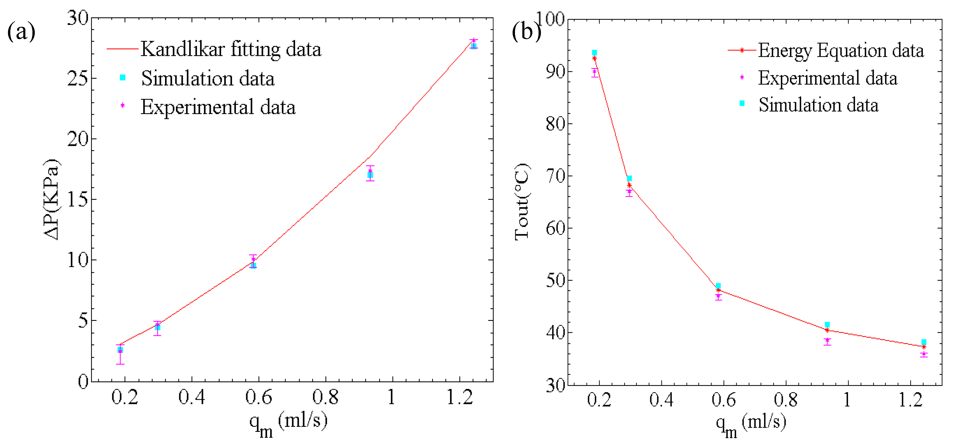
Figure 7 illustrates the trends in the pressure drop and outlet temperature characteristics derived from numerical simulations, theoretical calculations, and experimental measurements at various volumetric flow rates, using deionized water as the working fluid in the rectangular microchannel. It is evident that the pressure drop characteristics from the experimental measurements, the numerical simulations, and the fitting results of Kandlikar et al. exhibit a strong correlation, with a relative error within 8%. Regarding the thermal characteristics of the microchannel heat sink, the relative errors between the experimental measurements, theoretical temperature values, and numerical simulation temperature values are all within 5%. These results lead to the following conclusions: the established conjugate heat transfer numerical model effectively describes the flow and heat transfer characteristics in the microchannel, and the numerical analysis results accurately predict these characteristics. Additionally, the experimental test system satisfied the requirements for evaluating the flow and heat transfer performance of the microchannel heat sink.
Based on the optimized microchannel structure derived from theory and simulation, the flow and heat transfer characteristics of the IGBT module integrated with the microchannel were further investigated using nanofluids with volume fractions of 0.1%, 0.5%, and 1%, respectively. Regarding the flow and heat transfer characteristics in the microchannel with nanofluids, Moraveji et al. employed numerical simulation methods to study Al2O3-water nanofluid under laminar flow conditions with volume fractions ranging from 0 to 1.734%. They proposed a correlation formula describing the flow and heat transfer characteristics in microchannels, which includes parameters such as the volume fraction, Re, flow friction coefficient f, and heat transfer Nu [56]. With the development of microchannel liquid cooling technology, Zhai et al. further explored the flow and heat transfer characteristics of nanofluids in complex microchannels [57], considering the influence of the cavity structure in microchannels on the heat transfer characteristics of the fluid. The description formulas for the flow and heat transfer have been revised as follows:
water :   f 0 = 35.88 R e 0.91
N u 0 = 1.93 R e 0.2
nanofluids :   f n f = 37.23 R e n f 0.89 ( 1 + φ ) 39.54
N u n f = 0.46 R e n f 0.25 P r n f 0.62 ( 1 + φ ) 36.82
Due to the distribution of spoiler cavities in the microchannel, in the process of experimental analysis, the flow and heat transfer characteristic data under laminar flow were compared with the above equations.
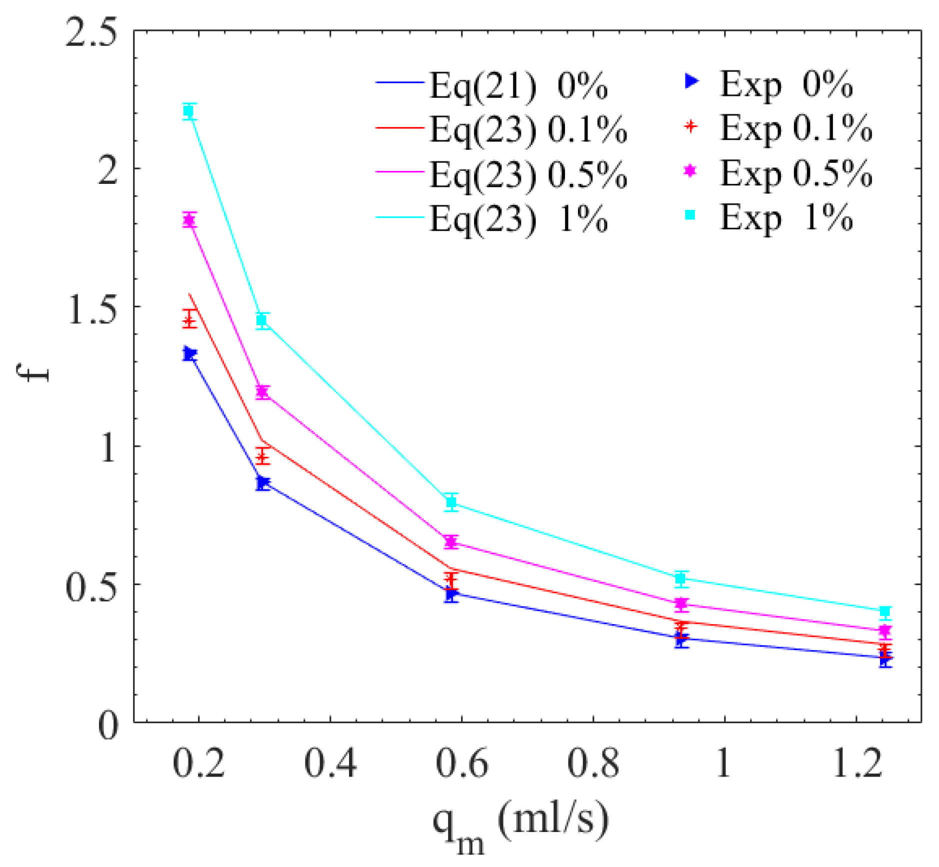
According to the analysis of experimental data, Figure 8 reveals that the friction coefficient decreased with increasing volumetric flow rate. Conversely, it increased with the rise in the volume fraction of nanofluids. In addition, the collected experimental data are in good agreement with Equations (21) and (23). The triangular cavities and circular cavities in the microchannel have almost identical effects on the pressure drop. Furthermore, microchannels configured with different internal spoiler cavities were found to have little impact on the pressure drop.
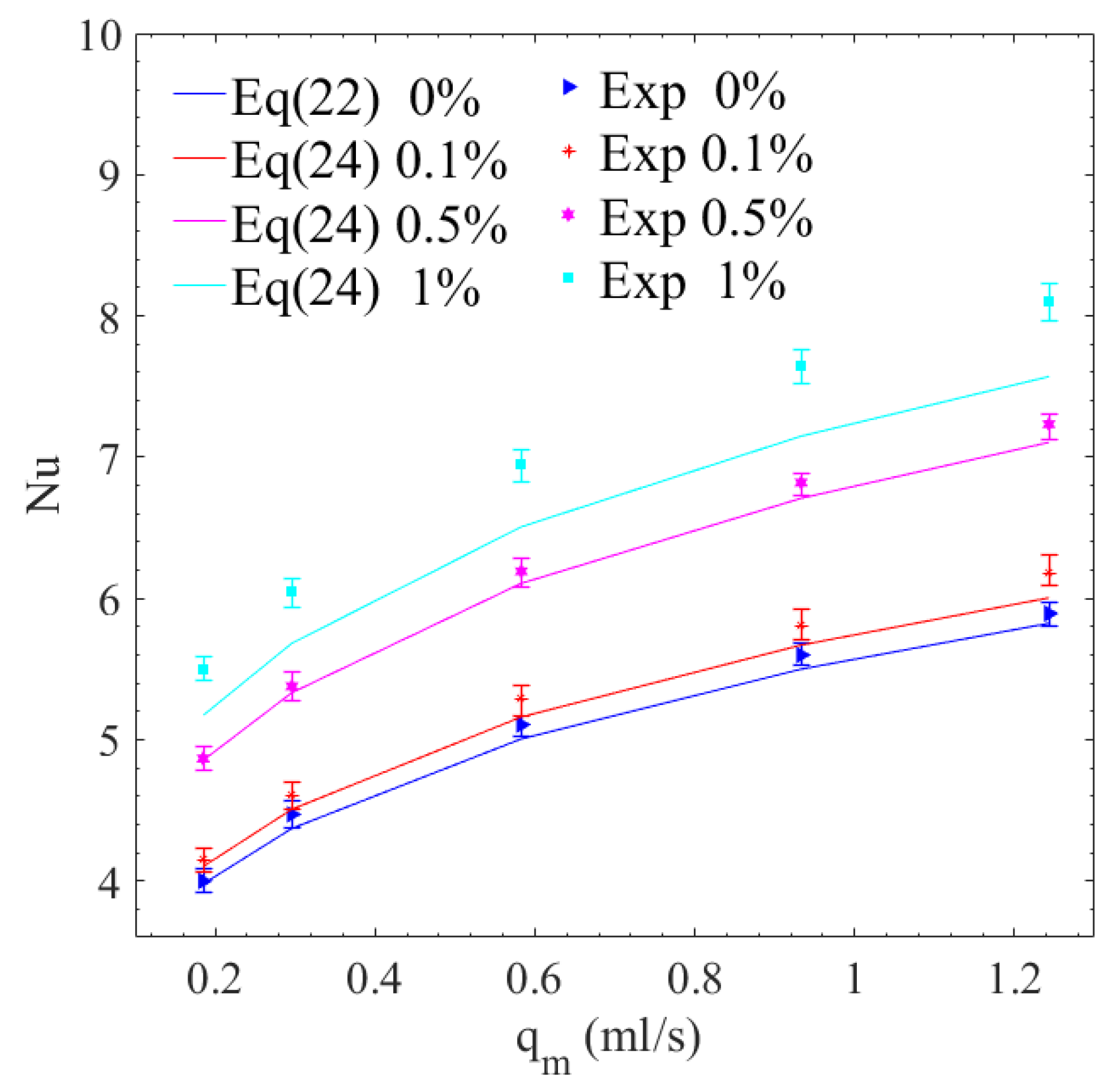
Figure 9 shows that the Nu values gradually increased as the volumetric flow rate rose under laminar flow conditions, and the larger the volumetric flow rate, the greater the increase. It was also observed that the Nusselt number increased gradually with the volume fraction of nanoparticles; due to the non-linearity of changes in thermal properties, this increasing trend was also non-linear. In addition, due to the different arrangements of the spoiler cavities in the microchannel, the Nu values obtained from experimental measurements differed from the Nu predictions from complex microchannels proposed by Zhai et al. [57]. The Nu value derived from experimental data were significantly higher than the predicted values from Equations (22) and (24).
Figure 8 and Figure 9 respectively show the trend of friction coefficient and the Nusselt number with flow rate under different nanoparticle volume fractions. The main reason is that the arrangement of the spoiler cavities in the microchannel has a great influence on multiple-effect coupling, including the perturbation effect formed by the cavities, the axial heat conduction effect, and the thermal boundary layer. Especially, this novel microchannel with internal spoiler cavities promoted the redevelopment of thermal boundary layer, which optimized the field synergy between the velocity field and the temperature gradient field in the whole fluid domain. Therefore, from the obtained experimental data, the current experimental measurements were higher than the correlations proposed in Equations (22) and (24). The experimental results also indicate that when nanofluids were used as the working fluid in the complex-structured microchannel heat sink, their heat transfer performance surpassed that of deionized water. The enhancement in heat transfer, as indicated by the Nusselt number, within the tested range was at least 38%.
In order to more clearly show the influence of the spoiler cavities structure on the thermal characteristics of the microchannel when nanofluids were used as the working fluid, Figure 10 shows the temperature distribution on the top surface of the microchannel heat sink under four distinct conditions at a volumetric flow rate of 1.2 mL/s. It is evident that the temperature along the top surface of the microchannel increased in the direction of flow. Moreover, when deionized water and nanofluids were utilized as the working fluids, the temperature of the microchannel featuring spoiler cavities was 2.5–4.2 °C and 2.6–3.4 °C lower than that of the rectangular microchannel, respectively. In addition, the heat transfer performance of both the rectangular microchannel and the microchannel with spoiler cavities was enhanced when nanofluids as the working fluid. Figure 10b,d show that when nanofluids were the working fluid, the maximum top surface temperature of the rectangular microchannel and the microchannel with spoiler cavities decreased by 1.7 and 0.9 °C, respectively. Therefore, it can be concluded that the optimized microchannel structure and the use of nanofluids significantly improve the heat transfer characteristics, with the influence of spoiler cavities being particularly pronounced.
According to the above analysis of the flow and heat transfer characteristics of the microchannel with internal cavities, it is evident that the combination of the optimized microchannel and nanofluids has a significant effect on improving heat dissipation performance. To assess the practical application of this optimized microchannel heat sink in products, the thermal management effectiveness of the integrated microchannel heat sink with the IGBT module under nanofluids was investigated.
In order to evaluate the combined effect of flow and heat transfer performance, the comprehensive heat transfer performance (PEC) of the optimized microchannel structure under nanofluids was analyzed. The formula for calculating the comprehensive heat transfer performance (PEC) is
P E C = ( N u n f / N u 0 ) ( f n f / f 0 ) 1 / 3
where Nunf and fnf respectively represent the Nusselt number and friction coefficient with nanofluids as the working fluid, and Nu0 and f0 respectively represent the Nusselt number and friction coefficient with water as the working fluid.
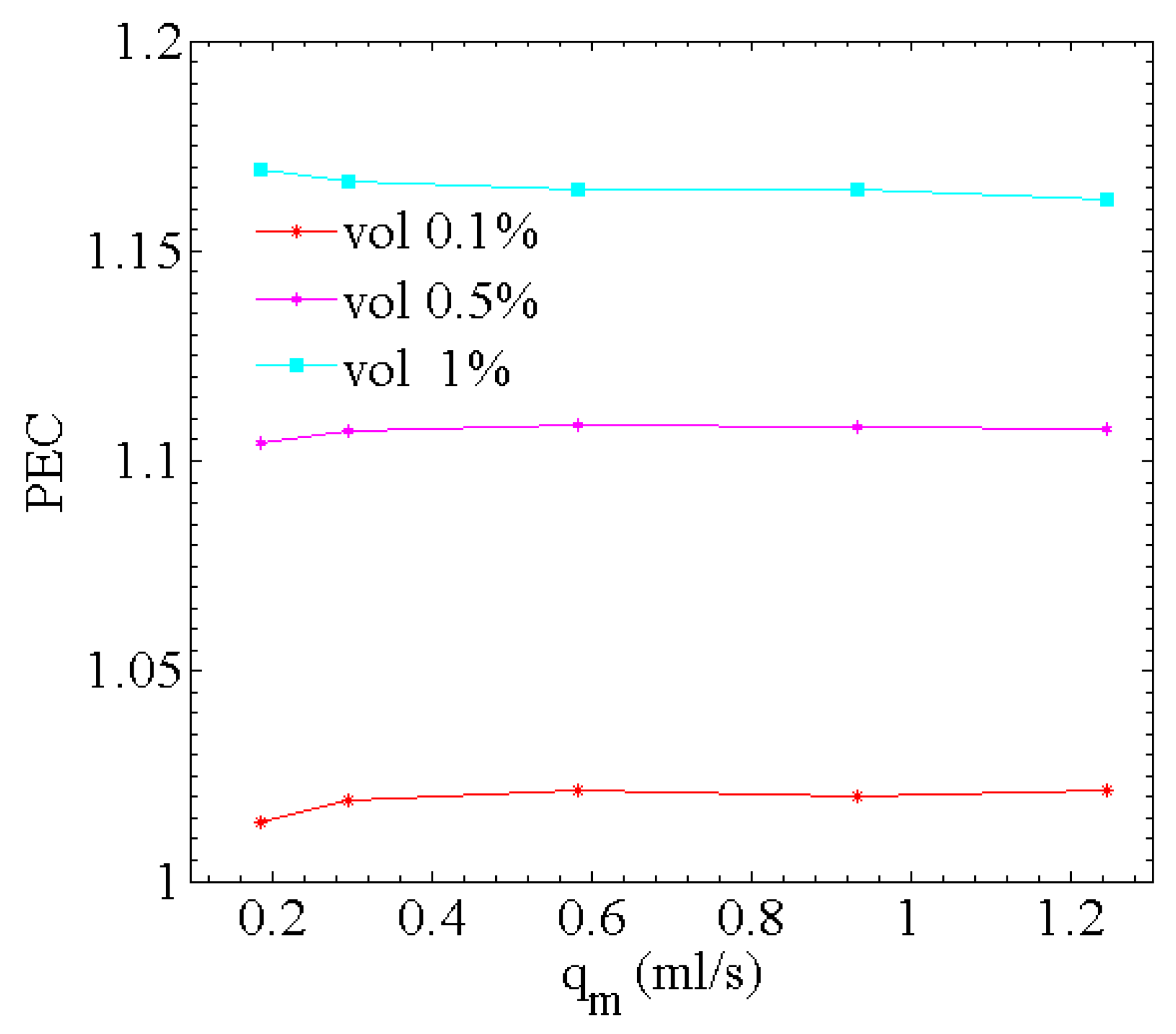
Figure 11 shows the variation curve of the PEC under different nanofluid’s volume fractions based on the measured experimental data and the calculation formula for comprehensive heat transfer performance. It is observed that the comprehensive heat transfer performance remained essentially unchanged within the tested flow range for the same volume fraction. Additionally, at the same volumetric flow rate of the working fluid, the PEC increased with rising nanoparticle volume fractions, with the comprehensive heat transfer performance of the microchannel using nanofluids exceeding that of deionized water by at least 20%. The experimental results reveal that the comprehensive heat transfer performance showed an improvement, with an increase in nanoparticle volume fraction. However, within the tested range, the comprehensive heat transfer performance of the microchannel remained largely unchanged for the same microchannel structure and working fluid.

5. Conclusions

In this work, the heat dissipation performance of an IGBT-integrated microchannel heat sink was systematically investigated through a combination of experiments and simulations. The main conclusions are summarized as follows:
  • By comparing experimental results with numerical simulation data, the reliability of the three-dimensional conjugate heat transfer model in analyzing the flow and heat transfer characteristics of the microchannel was verified. Additionally, the configuration of internal cavities in the microchannel was optimized based on the field synergy principle, and the feasibility and reliability of this optimization strategy were demonstrated.
  • Experiments were conducted to explore the feasibility of applying the novel microchannel structure to IGBT devices, providing critical experimental data to support the translation of this optimized design from theoretical research to engineering applications.
  • Based on the optimized microchannel structure, experimental results validated the heat transfer enhancement effect of nanofluids: Under the same microchannel configuration, when the flow rate was 0.6 mL/min and the heat flux of the cooled device was 100 W/cm2, the heat dissipation efficiency was improved by 38% using nanofluids compared to deionized water.
Building on the findings of this study on IGBT-integrated microchannel heat sinks, future research could focus on three aspects: first, optimizing the microchannel geometry to enhance the synergy between phase-change heat transfer and nanofluid turbulent flow, aiming to further reduce thermal resistance under high heat flux; second, exploring the long-term reliability of the heat sink under cyclic thermal loads, particularly the interface thermal resistance evolution between IGBT chips and microchannels; third, developing a multi-physics coupling model that integrates material thermal properties, flow dynamics, and device electrical performance to better guide practical engineering applications.

Author Contributions

Conceptualization, X.T. and H.H.; methodology, F.L. and Z.T.; software, F.L. and Z.T.; validation, W.Z. and Y.Z.; formal analysis, F.L. and H.H.; writing—original draft preparation, F.L. and Z.T.; writing—review and editing, H.H. and X.T.; supervision, W.Z. and H.H.; funding acquisition, Y.Z. All authors have read and agreed to the published version of the manuscript.

Funding

This work was supported by the National Natural Science Foundation of China (52175254).

Data Availability Statement

The data presented in this study will be made available by the authors upon reasonable request.

Conflicts of Interest

The authors declare no conflicts of interest.

References

  1. The International Technology Roadmap for Semiconductors (TIRS); Semiconductor Industry Association: Washington, DC, USA, 2006.
  2. Huang, R.; Wei, G.; Wang, X.; Jiang, B.; Zhu, J.; Chen, J.; Wei, X.; Dai, H. Revealing the low-temperature aging mechanisms of the whole life cycle for lithium-ion batteries (nickel-cobalt-aluminum vs. graphite). J. Energy Chem. 2025, 106, 31–43. [Google Scholar] [CrossRef]
  3. Du, L.; Hu, W. An overview of heat transfer enhancement methods in microchannel heat sinks. Chem. Eng. Sci. 2023, 280, 119081. [Google Scholar] [CrossRef]
  4. Tang, X.; Huang, H.; Zhong, X.; Wang, K.; Li, F.; Zhou, Y.; Dai, H. On-Line Parameter Identification and SOC Estimation for Lithium-Ion Batteries Based on Improved Sage–Husa Adaptive EKF. Energies 2024, 17, 5722. [Google Scholar] [CrossRef]
  5. Wang, Z.; Tang, X.; Zhou, Y.; Huang, H.; Dai, H. Experimental and Modeling Analysis of Thermal Runaway for LiNi0.5Mn0.3Co0.2O2/Graphite Pouch Cell Triggered by Surface Heating. Energies 2024, 17, 826. [Google Scholar] [CrossRef]
  6. Ben Hamida, M.B. Thermal management of square light emitting diode arrays: Modeling and parametric analysis. Multidiscip. Model. Mater. Struct. 2024, 20, 363–383. [Google Scholar] [CrossRef]
  7. Hamida, M.; Hatami, M. Optimization of fins arrangements for the square light emitting diode (LED) cooling through nanofluid-filled microchannel. Sci. Rep. 2021, 11, 12610. [Google Scholar] [CrossRef]
  8. Ben Hamida, M.B.; Almeshaal, M.A.; Hajlaoui, K.; Rothan, Y.A. A three-dimensional thermal management study for cooling a square Light Edding Diode. Case Stud. Therm. Eng. 2021, 27, 101223. [Google Scholar] [CrossRef]
  9. Tuckerman, D.B.; Pease, F.W. High-performance heat sinking for VLSI. IEEE Electron Device Lett. 1981, 2, 126–129. [Google Scholar] [CrossRef]
  10. Dong, W.; Zhang, X.; Liu, B.; Wang, B.; Fang, Y. Research progress on passive enhanced heat transfer technology in microchannel heat sink. Int. J. Heat Mass Transf. 2024, 220, 125001. [Google Scholar] [CrossRef]
  11. Zhu, Q.; Jin, Y.; Chen, J.; Su, R.; Zhu, F.; Li, H.; Wan, J.; Zhang, H.; Sun, H.; Cui, Y.; et al. Computational study of rib shape and configuration for heat transfer and fluid flow characteristics of microchannel heat sinks with fan-shaped cavities. Appl. Therm. Eng. 2021, 195, 117171. [Google Scholar] [CrossRef]
  12. Derakhshanpour, K.; Kamali, R.; Eslami, M. Effect of rib shape and fillet radius on thermal-hydrodynamic performance of microchannel heat sinks: A CFD study. Int. Commun. Heat Mass Transf. 2020, 119, 104928. [Google Scholar] [CrossRef]
  13. Narendran, G.; Mallikarjuna, B.; Nagesha, B.K.; Gnanasekaran, N. Experimental investigation on additive manufactured single and curved double layered microchannel heat sink with nanofluids. Heat Mass Transf. 2023, 59, 1311–1332. [Google Scholar] [CrossRef]
  14. Liu, L.; Zhang, L.; Zhang, X.; Xu, H.; Zhang, H.; Zhou, S.; Cao, Y. Thermohydraulic performance of the microchannel heat sinks with three types of double-layered staggered grooves. Int. J. Therm. Sci. 2024, 201, 109032. [Google Scholar] [CrossRef]
  15. Mezzanzanica, G.; Français, O.; Mariani, S. Surface Acoustic Wave-Based Microfluidic Device for Microparticles Manipulation: Effects of Microchannel Elasticity on the Device Performance. Micromachines 2023, 14, 1799. [Google Scholar] [CrossRef]
  16. Tian, Z.; Huang, Z.; Zhou, Y.; Cao, Z.; Gao, W. Design and experimental study on wave-type microchannel cooling plates for marine large-capacity battery thermal management. Appl. Therm. Eng. 2024, 236, 121571. [Google Scholar] [CrossRef]
  17. Zhang, X.; Ji, Z.; Wang, J.; Lv, X. Research progress on structural optimization design of microchannel heat sinks applied to electronic devices. Appl. Therm. Eng. 2023, 235, 121294. [Google Scholar] [CrossRef]
  18. Feng, Z.; Hu, Z.; Lan, Y.; Huang, Z.; Zhang, J. Effects of geometric parameters of circular pin-fins on fluid flow and heat transfer in an interrupted microchannel heat sink. Int. J. Therm. Sci. 2021, 165, 106956. [Google Scholar] [CrossRef]
  19. Foong, A.J.L.; Ramesh, N.; Chandratilleke, T.T. Laminar convective heat transfer in a microchannel with internal longitudinal fins. Int. J. Therm. Sci. 2009, 48, 1908–1913. [Google Scholar] [CrossRef]
  20. Shen, H.; Wang, C.; Xie, G. A parametric study on thermal performance of microchannel heat sinks with internally vertical bifurcations in laminar liquid flow. Int. J. Heat Mass Transf. 2018, 117, 487–497. [Google Scholar] [CrossRef]
  21. Chakraborty, R.A.S. Effect of micro-structures in a microchannel heat sink—A comprehensive study. Int. J. Heat Mass Transf. 2020, 154, 119617. [Google Scholar]
  22. Jung, S.Y.; Park, J.H.; Lee, S.J.; Park, H. Heat transfer and flow characteristics of forced convection in PDMS microchannel heat sink. Exp. Therm. Fluid Sci. 2019, 109, 109904. [Google Scholar] [CrossRef]
  23. Chen, C.; Liu, Y.; Li, J.; Shi, D.; Xin, G. Flow and heat transfer characteristics of manifold microchannels with different microchannel arrangements. Therm. Sci. Eng. Prog. 2025, 59, 103354. [Google Scholar] [CrossRef]
  24. Xia, G.D.; Chai, L.; Wang, H.; Zhou, M.; Cui, Z. Optimum thermal design of microchannel heat sink with triangular reentrant cavities. Appl. Therm. Eng. 2011, 31, 1208–1219. [Google Scholar] [CrossRef]
  25. Xia, G.; Chai, L.; Zhou, M.; Wang, H. Effects of structural parameters on fluid flow and heat transfer in a microchannel with aligned fan-shaped reentrant cavities. Int. J. Heat Mass Transf. 2011, 50, 411–419. [Google Scholar] [CrossRef]
  26. Xia, G.D.; Zhai, Y.; Cui, Z. Numerical investigation of thermal enhancement in a micro heat sink with fan-shaped reentrant cavities and internal ribs. Appl. Therm. Eng. 2013, 58, 52–60. [Google Scholar] [CrossRef]
  27. Zhai, Y.L.; Xia, G.D.; Liu, X.F.; Li, Y.F. Heat transfer in the microchannels with fan-shaped reentrant cavities and different ribs based on field synergy principle and entropy generation analysis. Int. J. Heat Mass Transf. 2014, 68, 224–233. [Google Scholar] [CrossRef]
  28. Bi, C.; Tang, G.H.; Tao, W.Q. Heat transfer enhancement in mini-channel heat sinks with dimples and cylindrical grooves. Appl. Therm. Eng. 2013, 55, 121–132. [Google Scholar] [CrossRef]
  29. Choi, S.U.S.; Eastman, J.A. Enhancing thermal conductivity of fluids with nanoparticles. In Proceedings of the ASME International Mechanical Engineering Congress & Exposition, San Francisco, CA, USA, 12–17 November 1995. [Google Scholar]
  30. Xuan, Y.; Roetzel, W. Conceptions for heat transfer correlation of nanofluids. Int. J. Heat Mass Transf. 2000, 43, 3701–3707. [Google Scholar] [CrossRef]
  31. Xuan, Y.; Li, Q. Investigation on Convective Heat Transfer and Flow Features of Nanofluids. J. Heat Transf. 2003, 125, 151–155. [Google Scholar] [CrossRef]
  32. Ho, C.J.; Wei, L.C.; Li, Z.W. An experimental investigation of forced convective cooling performance of a microchannel heat sink with Al2O3/water nanofluid. Appl. Therm. Eng. 2010, 30, 96–103. [Google Scholar] [CrossRef]
  33. Ho, C.J.; Chen, W.C. An experimental study on thermal performance of Al2O3/water nanofluid in a minichannel heat sink. Appl. Therm. Eng. 2013, 50, 516–522. [Google Scholar] [CrossRef]
  34. Wang, X.; An, B.; Xu, J. Optimal geometric structure for nanofluid-cooled microchannel heat sink under various constraint conditions. Energy Convers. Manag. 2013, 65, 528–538. [Google Scholar] [CrossRef]
  35. Wang, X.; An, B.; Lin, L.; Lee, D. Inverse geometric optimization for geometry of nanofluid-cooled microchannel heat sink. Appl. Therm. Eng. 2013, 55, 87–94. [Google Scholar] [CrossRef]
  36. Bianco, V.; Scarpa, F.; Tagliafico, L.A. Numerical analysis of the Al2O3-water nanofluid forced laminar convection in an asymmetric heated channel for application in flat plate PV/T collector. Renew. Energy 2018, 116, 9–21. [Google Scholar] [CrossRef]
  37. Bianco, V.; Marchitto, A.; Scarpa, F.; Tagliafico, L.A. Numerical investigation on the forced laminar convection heat transfer of Al2O3-water nanofluid within a three-dimensional asymmetric heated channel. Int. J. Numer. Methods Heat Fluid Flow 2019, 29, 1132–1152. [Google Scholar] [CrossRef]
  38. Marseglia, G.; De Giorgi, M.G.; Pontes, P.; Solipa, R.; Souza, R.R.; Moreira, A.L.N.; Moita, A.S. Enhancement of microchannel heat sink heat transfer: Comparison between different heat transfer enhancement strategies. Exp. Therm. Fluid Sci. 2024, 150, 111052. [Google Scholar] [CrossRef]
  39. Omri, M.; Smaoui, H.; Frechette, L.; Kolsi, L. A new microchannel heat exchanger configuration using CNT-nanofluid and allowing uniform temperature on the active wall. Case Stud. Therm. Eng. 2022, 32, 101866. [Google Scholar] [CrossRef]
  40. Jamshidmofid, M.; Abbassi, A.; Bahiraei, M. Efficacy of a novel graphene quantum dots nanofluid in a microchannel heat exchanger. Appl. Therm. Eng. 2021, 189, 116673. [Google Scholar] [CrossRef]
  41. Vinoth, R.; Sachuthananthan, B. Flow and heat transfer behavior of hybrid nanofluid through microchannel with two different channels. Int. Commun. Heat Mass Transf. 2021, 123, 105194. [Google Scholar] [CrossRef]
  42. Ajeeb, A.W.; Oliveira, M.S.A.; Martins, N.; Murshed, S.M.S. Forced convection heat transfer of non-Newtonian MWCNTs nanofluids in microchannels under laminar flow. Int. Commun. Heat Mass Transf. 2021, 127, 105495. [Google Scholar] [CrossRef]
  43. Wang, Y.; Li, W.; Qi, C.; Yu, J. Thermal management of electronic components based on hierarchical microchannels and nanofluids. Therm. Sci. Eng. Prog. 2023, 42, 101910. [Google Scholar] [CrossRef]
  44. Massoudi, M.D.; Hamida, M.B.B. Enhancement of MHD radiative CNT-50% water + 50% ethylene glycol nanoliquid performance in cooling an electronic heat sink featuring wavy fins. Waves Random Complex Media 2022, 16, 1–26. [Google Scholar] [CrossRef]
  45. Ben Hamida, M.B.; Hatami, M. Investigation of heated fins geometries on the heat transfer of a channel filled by hybrid nanofluids under the electric field. Case Stud. Therm. Eng. 2021, 28, 101450. [Google Scholar] [CrossRef]
  46. Ben Hamida, M.B.; Charrada, K.; Almeshaal, M.A.; Chamkha, A. A three-dimensional thermal analysis and optimization of square light edding diode subcomponents. Int. Commun. Heat Mass Transf. 2021, 120, 105016. [Google Scholar] [CrossRef]
  47. Li, F.; Zhu, W.; He, H. Numerical optimization on microchannel flow and heat transfer performance based on field synergy principle. Int. J. Heat Mass Transf. 2019, 130, 375–385. [Google Scholar] [CrossRef]
  48. Guo, Z.Y.; Li, D.Y.; Wang, B.X. A novel concept for convective heat transfer enhancement. Int. J. Heat Mass Transf. 1998, 41, 2221–2225. [Google Scholar] [CrossRef]
  49. Tao, W.Q.; He, Y.L.; Wang, Q.W.; Qu, Z.G.; Song, F.Q. A unified analysis on enhancing single phase convective heat transfer with field synergy principle. Int. J. Heat Mass Transf. 2002, 45, 4871–4879. [Google Scholar] [CrossRef]
  50. Tao, W.Q.; He, Y.L.; Chen, L. A comprehensive review and comparison on heatline concept and field synergy principle. Int. J. Heat Mass Transf. 2019, 135, 436–459. [Google Scholar] [CrossRef]
  51. Murshed, S.M.S.; Leong, K.C.; Yang, C. Investigations of thermal conductivity and viscosity of nanofluids. Int. J. Therm. Sci. 2008, 47, 560–568. [Google Scholar] [CrossRef]
  52. Lin, Q.; Li, Q.; Xu, P.; Zheng, R.; Bao, J.; Li, L.; Tan, D. Transport Mechanism and Optimization Design of LBM–LES Coupling-Based Two-Phase Flow in Static Mixers. Processes 2025, 13, 1666. [Google Scholar] [CrossRef]
  53. Albojamal, A.; Vafai, K. Analysis of single phase, discrete and mixture models, in predicting nanofluid transport. Int. J. Heat Mass Transf. 2017, 114, 225–237. [Google Scholar] [CrossRef]
  54. Li, F.; Zhu, W.; He, H. Field synergy analysis on flow and heat transfer characteristics of nanofluid in microchannel with non-uniform cavities configuration. Int. J. Heat Mass Transf. 2019, 144, 118617. [Google Scholar] [CrossRef]
  55. Steinke, M.E.; Kandlikar, S.G. Single-phase liquid friction factors in microchannels. Int. J. Therm. Sci. 2006, 45, 1073–1083. [Google Scholar] [CrossRef]
  56. Moraveji, M.K.; Ardehali, R.M. CFD modeling (comparing single and two-phase approaches) on thermal performance of Al2O3/water nanofluid in mini-channel heat sink. Int. Commun. Heat Mass Transf. 2013, 44, 157–164. [Google Scholar] [CrossRef]
  57. Zhai, Y.L.; Xia, G.D.; Liu, X.F.; Li, Y.F. Heat transfer enhancement of Al2O3-H2O nanofluids flowing through a micro heat sink with complex structure. Int. Commun. Heat Mass Transf. 2015, 66, 158–166. [Google Scholar] [CrossRef]
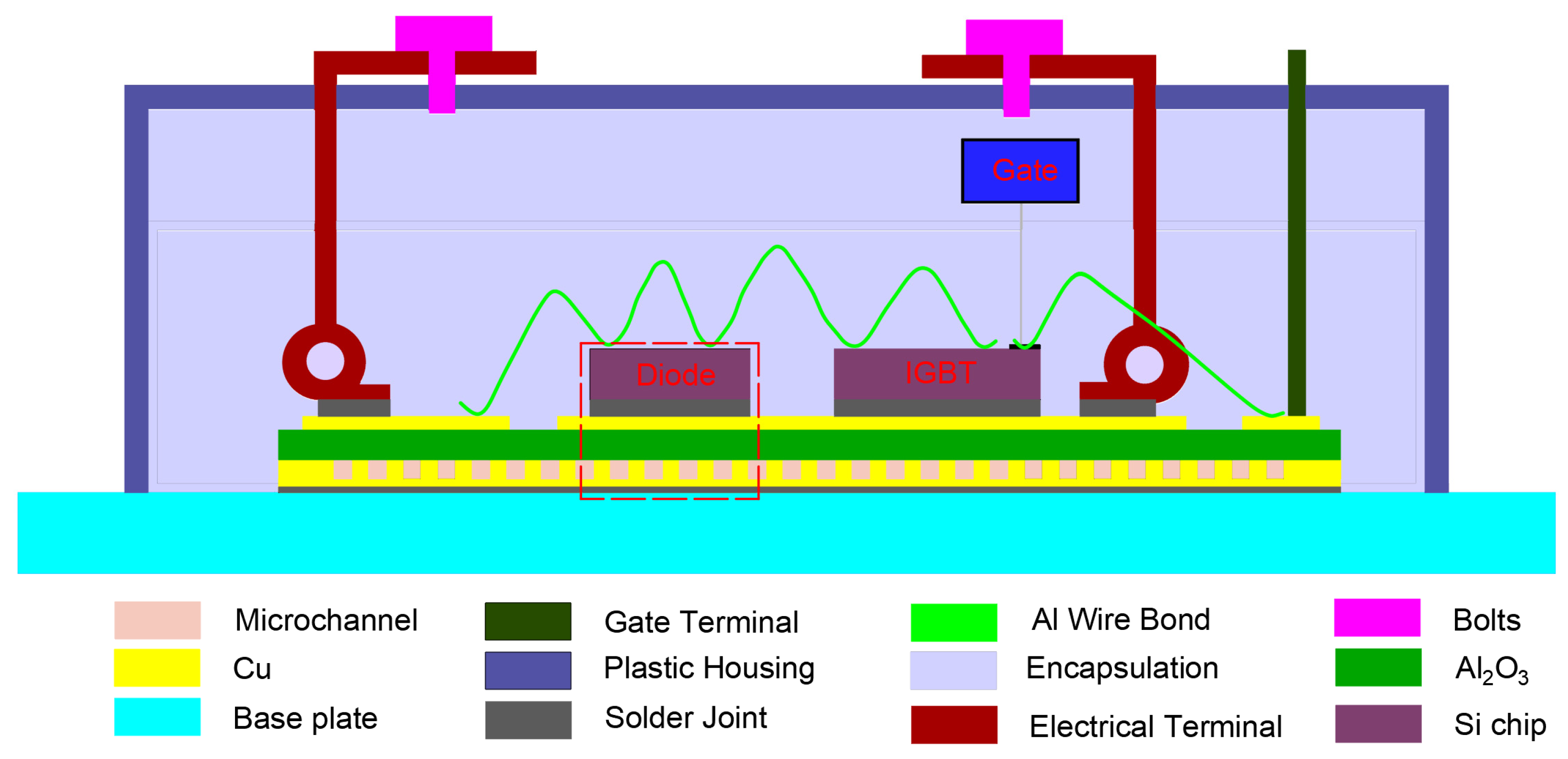
Figure 1. Schematic diagram of IGBT integrated MCHS.
Energies 18 04419 g001
Figure 2. Structure diagram of the MCHS integrated on the IGBT module.
Energies 18 04419 g002
Figure 3. The surface topography of microchannel: (a) partial three-dimensional depth map of microchannel with internal cavities, (b) partial enlarged view of microchannel with internal cavities, (c) depth map of microchannel, (d) partial enlarged view of rectangular microchannel.
Energies 18 04419 g003
Figure 4. Schematic diagram of the experimental system for microchannel flow and heat transfer testing.
Energies 18 04419 g004
Figure 5. The specific locations of temperature and flow measurement points.
Energies 18 04419 g005
Figure 6. Thermal balance deviation when using deionized water as working fluid in the microchannel.
Energies 18 04419 g006
Figure 7. Verification of the characteristics in the microchannel: (a) pressure drop characteristics, (b) thermal characteristics.
Energies 18 04419 g007
Figure 8. The change trend of friction coefficient of the test results and correlation equations values.
Energies 18 04419 g008
Figure 9. The variation trend of test results and correlation equations values of Nu under different volume fraction.
Energies 18 04419 g009
Figure 10. The temperature distribution of the top surface: (a) rectangular microchannel under deionized water, (b) rectangular microchannel under 1 vol% nanofluids, (c) microchannel with spoiler cavities under deionized water, (d) microchannel with spoiler cavities under 1 vol% nanofluids.
Energies 18 04419 g010
Figure 11. The PEC change trend under different volume fractions of optimized microchannel structure.
Energies 18 04419 g011
Table 1. Thermal properties of the Al2O3-water nanofluid with different volume fractions.
Vol %Density
ρ n f (kg/m3)
Specific Heat
C P , n f  ( J / kg · K )
Thermal Conductivity
k n f   ( W / m · K )
Dynamic Viscosity
  μ n f  ( kg / m · s )
Prandtl Number
Pr
0.11001.94169.30.64150.00101526.65
0.51013.54112.50.64350.00102316.55
11026.24043.60.65180.00103526.41
Table 2. Performance parameters of test equipment.
No. Equipment NameTypeMeasuring RangePrecision
1PumpCustomization, GB/T7782-20080–10 MPa0.166 mL/min
2Filter 400 eyes--40 μm
3Thermocouple TTJ36-CASS-010G-2−40–250 °C0.0075 T
4Digital pressure gauge GJM-1200–200 KPa0.05%
5Electronic scales FA1104N0–110 g0.1 mg
Disclaimer/Publisher’s Note: The statements, opinions and data contained in all publications are solely those of the individual author(s) and contributor(s) and not of MDPI and/or the editor(s). MDPI and/or the editor(s) disclaim responsibility for any injury to people or property resulting from any ideas, methods, instructions or products referred to in the content.