Article

Hybrid Adaptive Learning-Based Control for Grid-Forming Inverters: Real-Time Adaptive Voltage Regulation, Multi-Level Disturbance Rejection, and Lyapunov-Based Stability

1
School of Automation Science and Engineering, South China University of Technology, Guangzhou 510640, China
2
School of Industrial and Manufacturing Systems Engineering, Texas Tech University, Lubbock, TX 79403, USA
3
School of Electric Power, South China University of Technology, Guangzhou 510640, China
4
School of Electrical Engineering, Concordia University, Montreal, QC H3G 1M8, Canada
*
Authors to whom correspondence should be addressed.
Energies 2025, 18(16), 4296; https://doi.org/10.3390/en18164296
Submission received: 14 June 2025 / Revised: 5 August 2025 / Accepted: 7 August 2025 / Published: 12 August 2025

Abstract

This paper proposes a Hybrid Adaptive Learning-Based Control (HALC) algorithm for voltage regulation in grid-forming inverters (GFIs), addressing the challenges posed by voltage sags and swells. The HALC algorithm integrates two key control strategies: Model Predictive Control (MPC) for short-term optimization, and reinforcement learning (RL) for long-term self-improvement for immediate response to grid disturbances. MPC is modeled to predict and adjust control actions based on short-term voltage fluctuations while RL continuously refines the inverter’s response by learning from historical grid conditions, enhancing overall system stability and resilience. The proposed multi-stage control framework is modeled based on a mathematical representation using a control feedback model with dynamic optimal control. To enhance voltage stability, Lyapunov is used to operate across different time scales: milliseconds for immediate response, seconds for short-term optimization, and minutes to hours for long-term learning. The HALC framework offers a scalable solution for dynamically improving voltage regulation, reducing power losses, and optimizing grid resilience over time. Simulation is conducted and the results are compared with other existing methods.

1. Introduction

With the growing integration of renewable energy sources, GFIs are essential to maintaining the stability and dependability of contemporary electrical grids [1]. In order to keep grid voltage and frequency within reasonable bounds, GFIs are essential. Stable voltage control is severely hampered by disturbances like voltage sags and swells, which can be brought on by transient faults, load variations, or grid instability [2]. Overvoltage scenarios arise due to sudden load drops, line faults leading to voltage surges and improper reactive power compensation. Conventional control systems frequently find it difficult to continue operating during these disruptions, which can result in higher power losses, inefficient operations, and even possible equipment damage [3]. Consequently, it is now critical to have a sophisticated control algorithm that can optimize control choices, improve grid resilience, and dynamically adjust to real-time disturbances. Due to this, over the years, researchers have proposed the use of adaptive droop control, fault ride-through (FRT)/low voltage ride-through (LVRT), overvoltage protection, and DC link voltage stabilization [4,5,6]. A dynamic expansion of traditional droop control, adaptive droop control is used in power electronics to control frequency and voltage in decentralized power networks. To improve voltage and frequency stability, it instantly modifies the droop coefficients in response to system conditions. But there is trade-off between stability and response time. Aggressive droop coefficient adjustments can lead to instability and also have a complex parameter tuning which requires real-time computation to set optimal droop coefficients [7]. Inverters that have the ability to FRT/LVRT can stay connected to the grid instead of disconnecting during voltage sags or short circuits. When a voltage dip is brought on by a malfunction, the inverter reactive power is injected to aid in voltage recovery and lowers active power to avoid drawing too much current which prevents its power electronics from being overloaded by limiting current injection [8]. The control strategy decides whether to disconnect or keep the inverter connected based on predetermined grid code compliance curves. However, long-term fault ride-through may cause the power electronics parts to overheat and also has limited voltage sag tolerance. System oscillations could result from several inverters reacting violently, causing grid instability. When the grid encounters extreme voltage levels, overvoltage protection devices regulate the inverter’s output to prevent harm to power electronic components. However, it presents certain limitations such as slow response time issues [9]. DC link voltage stabilization ensures a steady DC bus voltage in power converters, preventing fluctuations that can lead to inverter shutdowns or instability. The DC link capacitor acts as an energy buffer, smoothing out power fluctuations. There are some limitations like that DC link capacitors degrade over time, reducing their ability to stabilize voltage, and sudden power surges or faults can exceed the capacitor’s stabilization capability [10]. To solve these problems and ensure stable voltage in GFIs, this study suggests a Hybrid Adaptive Learning-Based Control (HALC) methodology that combines Model Predictive Control (MPC) and reinforcement learning (RL). MPC works effectively in systems where it is essential to make quick predictions about future behavior. It predicts the state of the grid and adjusts control operations accordingly [11]. This enables the inverter to predict variations and make proactive adjustments in voltage regulation. By resolving an optimization issue using the system model as a basis, MPC offers an explicit optimal control solution. This ensures that over a brief time horizon, control measures will minimize voltage deviation [12]. MPC ensures stability which is perfect for systems with well-understood dynamics since it is based on a system model and can provide predictable, optimal, and stable control performance under known conditions [13]. It also has quick response as it performs effectively in situations requiring real-time adjustment due to brief, rapid disruptions. A precise model of system dynamics is necessary for MPC. If the model is not ideal, MPC’s performance may suffer in the event of grid disruptions, where dynamics may be unpredictable or changing quickly which is the main limitation [14]. The MPC in this paper has been modeled to solve this problem. RL’s strength is its capacity for both learning from and adapting to prior events. It is appropriate for complicated, uncertain, or poorly understood situations, such as grid disturbances, because it does not require a pre-defined model of the system [15]. By honing its control strategy through cumulative learning, RL steadily enhances its performance over time [16]. Because of this, RL works well for long-term grid-forming inverter optimization, because the system may experience fluctuating conditions over time [17]. It can work even in situations where the system model is unclear or challenging to create, which is advantageous in dynamic settings with a lot of uncertainty, such as grids that receive renewable energy inputs, and is also flexibly able to manage multi-variable, complicated, and nonlinear systems with ease, modifying control schemes in response to real-time observations [18]. Before reaching an optimal policy, RL algorithms may need a considerable amount of exploration (trial-and-error), which could result in less-than-ideal or unstable behavior throughout the learning stage [19]. It also has longer convergence time because it depends on learning from past data and real-world interactions; it could take longer to converge [20]. Despite promising results in simulation, the recent literature in RL-based and MPC-based voltage control for power systems highlights several critical limitations. RL methods suffer from safety concerns due to unsafe trial-and-error exploration, require large amounts of high-fidelity data, often do not generalize well beyond their training scenarios, and lack interpretability posing barriers to real-world deployment [21]. On the other hand, MPC approaches depend heavily on accurate models (e.g., grid impedance knowledge), involve complex online optimization that can challenge real-time feasibility, and demand careful tuning of cost–function weights. Hybrid RL–MPC architectures, while attractive for combining adaptability and predictive control, face additional challenges in integrating optimization solvers with neural networks, managing high computational overhead, and expanding state-space complexity due to solver-internal variables. Addressing these challenges remains an open research frontier [22,23]. To solve all the problems stated above, in this paper, a control law has been designed for MPC using Lyapunov-based stability analysis that ensures the Lyapunov function decreases over time, leading to system stability. Then, RL is modeled based on dynamic optimal control. Then, a control feedback loop is modeled for the GFIs. To produce a reliable and flexible voltage regulation system, the HALC algorithm combines the long-term learning capacity of RL and the instantaneous responsiveness predictive power of MPC. In addition to responding quickly to disruptions, this hybrid method helps GFIs anticipate possible voltage problems and improve their management strategies over time. The suggested method provides a novel way to improve the stability, effectiveness, and dependability of electricity grids by utilizing real-time data, short-term forecasts, and long-term learning. The novelty of this paper is that the proposed HALC is an innovative way to integrate RL and MPC for voltage regulation since it reduces the need for preset models or rules by allowing the system to self-improve over time based on historical performance. By integrating the advantages of self-learning control, predictive optimization, and real-time adaptation, all of which have not been thoroughly examined in the literature to date, the suggested HALC framework provides a complete solution for voltage regulation.
The following are the main contributions of this study:
  • A control strategy diagram for inverter regulation utilizing a feedback control mechanism designed whereby the voltage controller uses the integration of RL and MPC in a single framework is a major breakthrough since each control technique works in concert to give short, long, and rapid reactions to disturbances.
  • A control law for MPC has been formulated using Lyapunov-based stability analysis, ensuring that the Lyapunov function continuously decreases over time, thereby guaranteeing system stability.
  • RL is modeled based on dynamic optimal control using a system based on a Markov Decision Process (MDP) to describe the dynamic behavior for disturbance rejection and error reduction by minimizing time. To ensure the system is stable even under disturbances, constraints are set. Starting with the fastest, these constraints are divided into three rejection levels: slow, probabilistic, and fast rejection constraints. The ability of the system to respond to disturbances with different levels of certainty and response speed is specified at each level. By rejecting disturbances according to their intensity and dynamically modifying control techniques, the system’s adaptive nature improves the grid’s overall stability and resilience.
  • Different timeframes are used by the suggested system: milliseconds for instantaneous voltage adjustments, seconds for short-term optimization, and minutes to hours for long-term learning. The inverter’s ability to manage disruptions of different sizes and durations is guaranteed by this multi-stage system.
The rest of this paper is arranged as follows: Section 2 presents the problem formation. Grid-forming control techniques with a feedback control loop are modeled in Section 3. The methodology of the control is explained in Section 4. In Section 5, the results of the experiment and simulation are presented, and the effectiveness of the suggested method is examined. The work is finally concluded in Section 5, which also suggests options for future research.

2. Problem Formation

2.1. Problem Statement

GFIs play a crucial role in maintaining voltage stability and power quality in modern power grids. However, they face challenges due to voltage sags and swells caused by fluctuating loads and renewable energy integration, the need for real-time control actions that ensure grid stability and the requirement for long-term adaptive learning to improve performance over time [24]. To address these challenges, an HALC approach is proposed, integrating MPC for short-term optimization and RL for long-term learning.

2.2. Model Predictive Control for Short-Term Optimization

Model Predictive Control (MPC) is a sophisticated control strategy that optimizes inverter performance over a short-term prediction horizon (N steps). Unlike traditional feedback controllers that react to errors after they occur, MPC proactively adjusts control actions by forecasting future system behavior and minimizing deviations before they impact stability [25]. The key steps in the MPC framework for grid-forming inverters (GFIs) are the real-time measurement and state estimation. For the system modeling and prediction, a discrete-time dynamic model of the inverter and grid is used to predict voltage and frequency evolution over the next N steps. The prediction model accounts for the inverter dynamics (switching behavior, filter dynamics), load variations and grid disturbances, and power balance constraints. MPC solves a constrained optimization problem at each time step to determine the best control actions ( u k ).
Optimization Objective: Minimize the voltage deviation and power loss over a prediction horizon N :
J = k = 1 N V r e f V k 2 + λ P l o s s    
where V r e f is the reference voltage, V k is the predicted voltage at step k , P l o s s represents power losses, λ is a weighting factor to balance voltage regulation and efficiency.
Constraints: Voltage and frequency limits:
V m i n V k V m a x ,   f m i n f k f m a x
Power balance:
P i n v e r t e r + P l o a d = P g r i d
Control action limits:
u m i n u k u m a x
where u k represents the inverter control signal at time step k .
The constraints are used by MPC to anticipate disturbances (e.g., sudden load changes) and preemptively adjust inverter output and reduce voltage and frequency deviations compared to PI-based control. The cost function minimizes losses while regulating voltage while it optimizes switching frequency and conduction losses. MPC enhances grid-forming inverters by combining predictive modeling, optimization, and constraint handling to achieve superior dynamic response and stability. This approach ensures robust performance in weak grids or high-renewable-penetration scenarios where traditional controls may falter.

2.3. Reinforcement Learning for Long-Term Learning

RL is employed to enhance the long-term adaptability and robustness of the GFI controller by leveraging historical and operational grid data [26]. Unlike short-horizon control methods such as MPC, which are limited to immediate prediction windows, RL continuously refines its control policy based on accumulated experience from past voltage disturbance events, power fluctuations, and frequency deviations [27]. This capability enables the controller to evolve over time and improve its performance under varying grid conditions, including weak-grid and high-renewable-penetration scenarios. In the proposed architecture, the RL agent is embedded within the GFI control framework and acts as a supervisory decision-making layer. Its primary objective is to identify optimal long-term control strategies that reduce voltage deviations, mitigate power losses, and enhance frequency stability, even under persistent or slowly evolving disturbances.

2.3.1. MDP Formulation of the GFI RL Problem

The control problem is formulated as a Markov Decision Process (MDP), represented by the tuple
M = S , A , p , r , γ
State space: The RL agent perceives the environment through measurable or estimated grid indicators, which capture both instantaneous and aggregated system conditions:
Voltage deviation: s 1 = V a c t u a l V n o m i n a l
Power fluctuations: s 2 = P l o a d P g e n e r a t e d
Frequency deviation: s 3 = f a c t u a l f n o m i n a l
This set of states ensures that both steady-state and dynamic aspects of grid stability are incorporated into the decision-making process.
Action space A : The RL agent influences inverter operation through a set of control actions, including the following:
a 1 : V s e t is the voltage reference adjustment. a 2 : K v , a 3 : K f are voltage and frequency droop coefficient modification.
a 4 is the modification of higher level control parameters learned from historical performance
These actions enable adaptive tuning of the inverter’s control behavior to maintain stability while optimizing efficiency.
Reward function  R s , a : The RL agent evaluates each state–action pair based on its impact on system performance. The reward function penalizes undesirable deviations while allowing trade-offs between stability and efficiency:
R = V a c t u a l V n o m i n a l β P l o s s
where P l o s s is the inverter power loss and β is a tunable weight factor that balances voltage regulation against efficiency considerations. The RL model is updated periodically and works alongside MPC for real-time optimization.
Transition probability p s s , a :   Represents the uncertain and potentially nonlinear dynamics of the inverter–grid system. The RL framework does not require explicit prior knowledge of p , instead learning it implicitly from interactions.
Discount factor γ 0 , 1 : Determines the weighting of long-term versus short-term performance, with higher values encouraging decisions that improve future stability.

2.3.2. Learning Mechanism and Policy Update

The RL agent seeks an optimal policy π * : S A that maximizes the expected cumulative discounted reward:
π * = arg m a x π E t = 0 γ t r s t , a t
The learning process proceeds iteratively:
1.
Observation: The agent records system states ( s t ) from real-time measurements and state estimators.
2.
Action selection: An action a t is chosen according to the current policy π t , with a balance between exploration (testing new control strategies) and exploitation (applying known optimal actions).
3.
Environment transition: The inverter–grid system evolves to a new state s t + 1 following the applied action and external disturbances.
4.
Reward evaluation: The immediate reward r t is computed using the performance metrics in (6).
5.
Policy update: The policy parameters are adjusted using collected experience, e.g., via Q-learning, policy gradient methods, or actor–critic architectures.
This update cycle is performed periodically rather than at every control interval, reducing computational burden and ensuring compatibility with MPC’s faster real-time decision-making.
The RL coordination with MPC, the RL component operates in parallel with MPC in a hybrid structure. MPC provides short-term, model-based optimization over horizon N , ensuring immediate stability and adherence to operational constraints. RL provides long-term, model-free optimization, continuously adapting high-level setpoints, droop parameters, or tuning coefficients for the MPC based on historical and predicted performance trends. This division of roles ensures that the system benefits from MPC’s fast corrective actions and RL’s capacity for continuous improvement in uncertain and evolving environments.

3. Modeling of Voltage Control Feedback Loop of Grid Forming Inverters

Figure 1 illustrates the control strategy diagram for inverter regulation utilizing a feedback control mechanism. The output voltage, current, and frequency are continuously monitored by the inverter, which compares the measured values with predetermined reference values that correspond to operating conditions and grid requirements. For the control structure, the inverter receives a DC voltage input V s and converts it into AC to supply the grid. It interacts with the output filter components (RLC) to shape the voltage V i and current i appropriately before interfacing with the grid. This RL filter with a capacitor smoothens the voltage waveform to ensure high-quality AC power delivery. The measured quantities after filtering are   V i , which is the output voltage, and i i is the inverter output current. For the voltage control loop, V i is fed into the voltage controller, which compares it against the desired reference voltage. The controller calculates the error between actual and reference voltage and compensates for any deviation. To address practical system dynamics, delay compensation methods such as model-based feedforward compensation is incorporated to mitigate computational and hardware-induced delays within the control loops. Additionally, tuning of controller parameters (e.g., PI gains, filter cut-off frequencies) is performed through fine-tuning based on time-domain simulation responses to optimize transient performance and stability margins. A delay block is introduced here to account for computational or hardware delays. The processed signal feeds into the power calculation block. The current control loop, i i , goes into the current controller, which regulates the current by comparing it to its reference value. An error is computed for current, and a delay is also included. This block determines the real and reactive power contributions to the grid using the outputs from the voltage and current controllers. The calculated power information is sent to the grid block, which represents the grid connection point. The grid receives the controlled power from the inverter. Any variations or disturbances from the grid (e.g., load changes, faults) propagate back into the system and influence the feedback loops. The control structure employs a dual-loop strategy with an outer voltage control loop and an inner current control loop to regulate the grid-forming inverter (GFI). The voltage controller ensures that the inverter’s output voltage V i tracks the reference value, while the current controller regulates the output current i i to maintain stability under varying load conditions. Error computation and delay compensation are integrated into both loops to reflect practical system dynamics. A centralized power calculation block processes feedback from both controllers to determine the power injected into the grid. This hierarchical approach ensures precise voltage and current regulation, rapid response to grid disturbances, and improved overall system stability, as illustrated in Figure 1.

4. Methodology

The proposed HALC framework employs Lyapunov-based stability analysis to ensure robust and reliable operation of grid-forming inverters under both short-term predictive control and long-term adaptive learning. Lyapunov methods are particularly suitable because they do not require linearization of the system dynamics and can rigorously prove convergence to equilibrium in the presence of nonlinearities, time-varying dynamics, and disturbances. MPC with a Lyapunov-based approach is used to ensure stability for the short-term, while for the long-term, since it is more complex, RL has been modeled using dynamic optimal control and Lyapunov stability for disturbance rejection, error minimization and fast tracking. Table 1 provides quick reference for the variables used in the HALC framework:

4.1. Mathematical Model for Lyapunov-Based Stability in MPC

To implement Model Predictive Control (MPC), the system was represented in discrete-time state-space form. The grid-forming inverter (GFI) with output filters and the connected grid impedance were modeled to capture voltage, current, and power dynamics accurately. The system dynamics are expressed as follows:
x ˙ t = A x t + B u t + E d t
y t = C x t + D u t
where x t is the state vector, comprising the inverter filter inductor current ( i L ), capacitor voltage ( v C ), and grid-side current ( i g ). u t   is the control input vector, representing the inverter output voltage commands. d t   represents external disturbances such as load variations and renewable power fluctuations. y t   is the output vector, including grid voltage and current measurements. A, B, C, D, and E are the system matrices derived from the inverter and grid parameters.
The continuous-time state-space matrices are expressed as follows:
A = R f L f 1 C f                                       1 L f 1 R g C f ,   B = 1 L f 0 ,   C = 0               1 ,   D = 0
where L f   and   C f are the inverter filter inductance and capacitance and R f   and   R g are the filter and grid-side resistances, respectively.
The model was discretized with a sampling time T s = 50   μ s to suit the MPC design. The discretized system is as follows:
x k + 1 = A d x k + B d u k + E d d k
y k = C d x k + D d u k
where A d ,   B d ,   C d ,   and   D d are the discrete-time matrices obtained using zero-order hold.
This state-space model serves as the prediction model in MPC to estimate future states over the prediction horizon N and compute the optimal control action within the control horizon M.
To ensure the stability of a system controlled by MPC, we use a Lyapunov-based approach. The fundamental idea is to design a control law that ensures the Lyapunov function decreases over time, leading to system stability.
Consider a discrete-time nonlinear system modeled as follows:
x t + 1 = f x t , u t
where x t n   is the system state at time t , u t m   is the control input, and f : n × m n is the system transition function
The objective of MPC is to find a control sequence u 0 : N 1   that minimizes a cost function while ensuring stability.
The Lyapunov function V x is a positive definite function that satisfies
V x > 0 ,   x 0 ,   V 0 = 0
To guarantee stability, the Lyapunov function must decrease over time:
V x t + 1 V x t Q x t , u t
where Q x t , u t is a positive definite function ensuring energy dissipation over time.
The predictive control strategy solves the following finite-horizon optimal control problem:
m i n u 0 : N 1 t = 0 N 1 Q x t + R u t + V x N  
Subject to system dynamics constraint: x t + 1 = f x t , u t , control constraints: u t U ,   and state constraints: x t X . Where Q x t   is a positive definite state cost, R u t is a positive definite control cost, and V ( x N ) is a terminal cost function ensuring stability at the end of the horizon.
For stability condition (Lyapunov decrease condition), the terminal cost function V x   must satisfy the following:
V x t + 1 V x t Q x t , u t ,   t 0
This ensures that as time progresses, the system state remains bounded and converges to equilibrium. To guarantee stability at all times, the control law must ensure recursive feasibility, meaning that if a feasible solution exists at t = 0 , then a feasible solution will always exist for t > 0 . Thus, the Lyapunov-based MPC controller ensures that the system remains stable by choosing an optimal sequence of control inputs u t such that the Lyapunov function always decreases, enforcing convergence towards a stable equilibrium.
The MPC formulation with Lyapunov constraints ensures recursive feasibility and stability under nonlinear dynamics.

4.2. Reinforcement Learning

A popular machine learning approach for handling sequential decision-making issues under uncertainty is reinforcement learning (RL). In contrast to conventional control techniques, RL can be applied directly to systems with uncertain dynamics f   and does not require a preset dynamics model f ¯ . However, many RL techniques’ usefulness in situations requiring safe management is limited by their lack of explicit assumptions and constraints. By engaging with the system and initially performing random actions to collect data, RL algorithms seek to optimize a policy π* over time and enhance our understanding of f . The trade-off between behaving greedily based on available data and investigating novel behaviors is a major problem in reinforcement learning. Taking less-than-ideal and possibly dangerous behaviors u in order to better comprehend f ¯   is a common practice in exploration, which may jeopardize safety while learning.
Generally, reinforcement learning (RL) makes the assumption that a Markov Decision Process (MDP) can be used to simulate the underlying control problem which is defined as A , S , p , r , γ . Where A is the action space, S is the state space, p is the state transition probability, r is the reward function, and γ is the discount rate.
RL complements MPC by learning optimal policies for uncertain long-term dynamics while respecting stability constraints.

4.3. Dynamic Optimal Control with Reinforcement Learning

Since our aim is to reduce error and also the disturbance rejection by minimizing time, a system is modeled based on a MDP to describe the dynamic behavior using discrete time model as follows:
x t + 1 = f t x t , u t , w t
where t is the discrete time index; x t     is the state space; u t is the input space, which is also the action space; f t     is the dynamic model; and w t   is the disturbance.
Based on (10), the state transition probability can be obtained as follows:
T t ( x t + 1 | x t , u t )
To calculate for the system’s error, we consider a finite-horizon optimal control problem with time horizon k . The objective is to identify the ideal order given an initial state space x 0 ; the error is calculated using the error sequence of the state space x 0 : k = x 0 , x 1 , , x k and the initial input space u 0   using u 0 : k 1 = u 0 , u 1 , , u k 1 The system error can be calculated as follows:
e x 0 : k ,   u 0 : k 1 = e k x k + t = 0 k 1 e t ( x t , u t )
where e k is the error at each step t and e t   is the error at the end of k -step horizon.
The discounted reward functions are obtained as follows:
e t = γ t r t ( x t , u t )
where r t is the reward function and γ is the discount factor of [0,1].
The HALC algorithm guarantees stability via MPC while achieving adaptability through RL, validated by Lyapunov analysis.

4.4. Dynamic Optimal Control with Reinforcement Learning for Disturbance Rejection

To ensure the system is stable even under disturbances, constraints are set. In order to provide constraints for disturbance rejection, we present n c  constraint functions c t x t , u t , w t where each c t i represents a real-valued, time-varying function. Starting with the fastest, these constraints are divided into three rejection levels: slow, probabilistic, and fast rejection constraints. The ability of the system to respond to disturbances with different levels of certainty and response speed is specified at each level.
For fast disturbance rejection constraint, the system should satisfy the following:
c t i x t , u t , w t 0
where for all times t 0 , , k and constraint indexes i 1 , , n c .
For probability disturbance rejection constraint, the system should satisfy the following:
p ( c t i x t , u t , w t ) 0 p i
where p is the probability and p i is the likelihood of the i t h   constraint rejection with i 1 , , n c   and for all times t 0 , , k .
For slow disturbance rejection constraint, the system should satisfy the following:
c t i x t , u t , w t ϵ i
where ϵ is a vector including all ϵ i     elements by which ϵ 0 . For all times t 0 , , k and constraint indexes i 1 , , n c .
The expected total disturbance rejection for the constraints is obtained as follows:
T c i = E t = 0 k 1 c t i x t , u t , w t d i
where T c i     represents the total expected constraint, d i is the equivalent constraint limit, and E is the expected value. It uses the discounted constraint function of γ t c t i x t , u t , w t .
The unified framework ensures fast transient response (MPC) and long-term robustness (RL), critical for GFI operation in dynamic grids.

4.5. Dynamic Optimal Control with Reinforcement Learning for Stability Analysis

The core elements of the system control issue are represented by the functions previously defined: specifically, the system model f , the constraints c , and the error function e . The functions f , c , and e may be completely or partially unknown. We suppose that each of these true functions f , c , and e can be broken down into two parts without losing generality, thereby maintaining its actual forms: an unknown part that can be gained from data and a nominal part that represents past acquisition.
The dynamic model of the system’s stability is obtained as follows:
f t x t , u t , w t = f t ¯ x t , u t + f ^ t x t , u t , w t
where f   ¯   and f ^     are the initial and uncertain state model, respectively.
RL uses initial gain η = { f ¯ ,   c ¯ ,   e ¯ } and the data obtained from the dynamic model τ = x j , u j , c j , e j , j = D and j = 0   to find a policy or controller π t x t that completes the task at hand while adhering to all rejection regulations.
R L : η , τ π t
where, η is the sample quantity and τ is the size of the data set. The policy we aim to find is its adaptation to change in uncertainties that occur. When the policy is obtained, the system becomes stable. The policy π t     we aim to achieve is the best estimation of the true optimal policy π t * .
Which is obtained as follows:
e π * x   ¯ 0 = m i n π 0 : k 1 , ϵ e x 0 : k ,   u 0 : k 1 + ϵ
x t + 1 = f t x t , u t , w t , t 0 , , k 1
u t = π t x t
x 0 = x   ¯ 0
The dynamic model is sampled using the following:
x t = x t Δ t 1
where Δ t 1 is the sampling time.
So, the discrete control input is obtained as follows:
u t = u t Δ t 1
It is kept constant with time interval using [t Δ t 1 , t + 1 Δ t 1 ) .
Because Lyapunov stability analysis offers a strong, methodical way to evaluate whether a system will stay stable or converge to a desired equilibrium state without necessarily requiring a thorough solution to the system’s equations of motion, we use it to determine the stability of dynamical systems.
Using Lyapunov stability analysis for the model stability, we obtain
x t + 1 = f x ¯ x t + f u ¯ x t u t + f θ ¯ x t θ
where f x ¯ , f u ¯ , and f θ ¯   are known functions derived from the first principle. θ is a possible bounded set of parameters.
The control input based on Lyapunov stability analysis is
u t = π ( x t , θ ^ t )
Considering a closed-loop system under some policy, we obtain the following:
π x : x t + 1 = f π x t = f x t , π ( x t )
Under Lyapunov function, if L maps states to strictly lower values under closed-loop state feedback, we obtain the following:
Δ L x = L f π x t L x < 0
This suggests that the state approaches the origin’s equilibrium. For continuous-time systems, a similar formulation based on the derivatives of L exists.
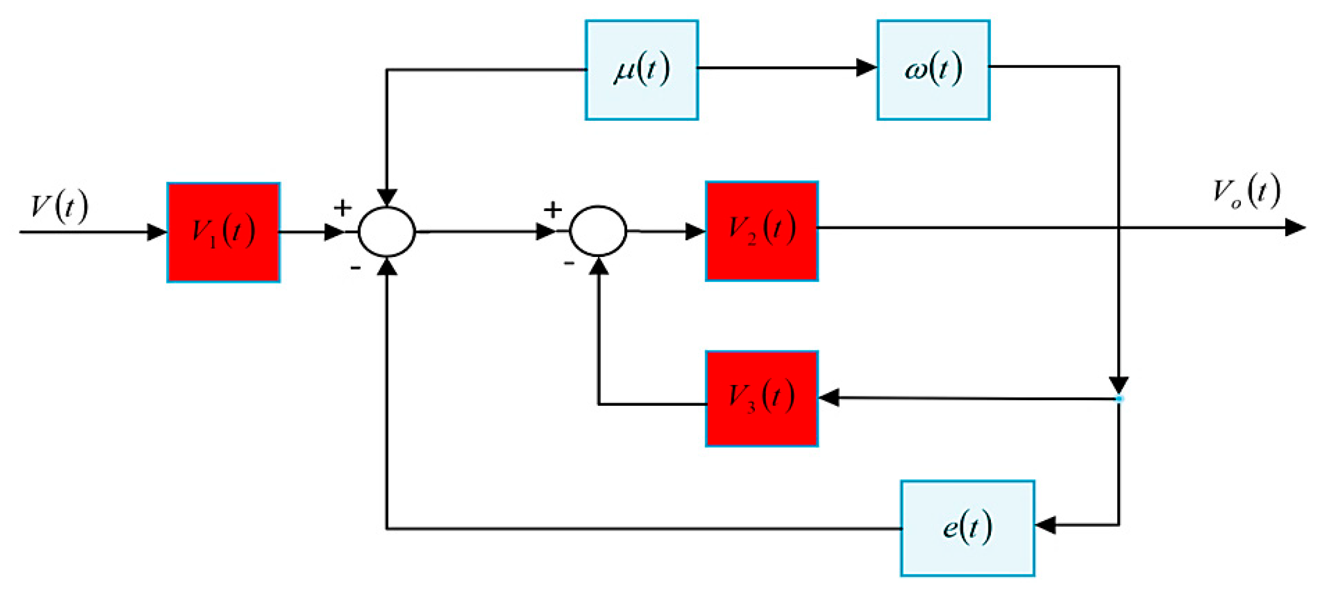
The Lyapunov stability function as defined in Equation (26) preserves voltage stability in the event of disturbance and errors in voltage measurement. Equation (32) detects change variation and calculates voltage control time while regulating voltage as it moves along the trajectories of the system. By applying these techniques, the control flow diagram for the Lyapunov stability function guarantees voltage stability even in the face of disturbance in the output voltage and external disturbances as defined in Equation (33) and Equations (34) and (35). As shown in Figure 2, the voltage control strategy employs a Lyapunov stability function to ensure system stability under varying operating conditions. The control law is derived based on the Lyapunov function candidate, which guarantees that the system’s voltage trajectory remains bounded and converges to a stable equilibrium point. This approach facilitates robust control performance even in the presence of disturbances or model uncertainties, by continuously evaluating the derivative of the Lyapunov function and adjusting control inputs to ensure it remains negative definite. As depicted in Figure 2, µ t   is the control input modulation signal, ω t     is the system frequency, v t , v 1 t , v 2 t ,   and   v 0 t   are the intermediate and output voltages, and   e t     is the tracking error. It illustrates the dynamic coupling between control input µ t , internal voltages, and the resulting error signal. The nested voltage terms ( v 1 t , v 2 t ) reflect the inverter’s filter dynamics, while e t quantifies regulation performance.
The dual-component model (nominal + uncertain) allows RL to adaptively compensate for unmodeled dynamics while the Lyapunov criteria maintain stability.

4.6. Analytical Stability and Optimality for HALC Algorithm

For analytical stability and optimality, the HALC algorithm combines Model Predictive Control (MPC) and reinforcement learning (RL) into a hybrid scheme for voltage regulation in GFIs. When combined, MPC handles fast dynamics and local disturbances and RL modifies control parameters based on accumulated knowledge. This hybrid architecture achieves both transient response optimization and long-term adaptability.
At each time step t :
The RL agent observes the grid state:
S t = V a c t u a l V n o m i n a l P l o a d P g e n e r a t e d f a c t u a l f n o m i n a l
Based on s t , RL suggests adaptive parameters:
a t = V s e t K v K f
The MPC layer solves the following optimization problem over a finite prediction horizon N p :
m i n u k i = t t + N p V k V n o r m a l 2 + β P l o s s i 2      
Subject to system constraints:
V m i n V k V m a x u m i n u k u m a x
Lyapunov-based stability analysis of MPC, combined with the monotonic improvement property of RL, confirms that the HALC algorithm stabilizes voltage deviations:
V a c t u a l V n o m i n a l 0     as   t t + N p
V a c t u a l V n o m i n a l , with bounded control actions and minimized P l o s s .
This hybrid mechanism allows MPC to react to immediate disturbances and RL to gradually improve control adaptability.
To analytically confirm HALC’s effectiveness in voltage regulation, we considered the following: MPC computes an optimal sequence of control inputs that minimize voltage deviation and power loss over a finite horizon.
MPC guarantees the existence of a control Lyapunov function V x such that
V ( x t + 1 ) V ( x t ) α x t x *
where x * is the equilibrium point ( V a c t u a l = V n o r m a l ) 0 .
The hybrid system inherits the stability of MPC and the adaptability of RL. MPC guarantees bounded voltage deviations for all t within the prediction horizon. RL tunes the MPC parameters V s e t ,   K v ,   K f to improve performance under uncertainty.
The Lyapunov function for the HALC algorithm is as follows:
L x , π = V M P C x + η V RL π
where V M P C x   is the Lyapunov function for MPC stability, η V RL π is the Lyapunov function for RL policy convergence, and η > 0 is the scaling parameter.
We obtain the following:
Δ L = L x t + 1 , π t + 1 L x t , π t < 0
implying global stability and adaptability.
The HALC algorithm’s hybrid architecture inherits the robustness of MPC and the adaptability of RL, with formal guarantees of stability and optimality.

4.7. Proposed Control System Diagram

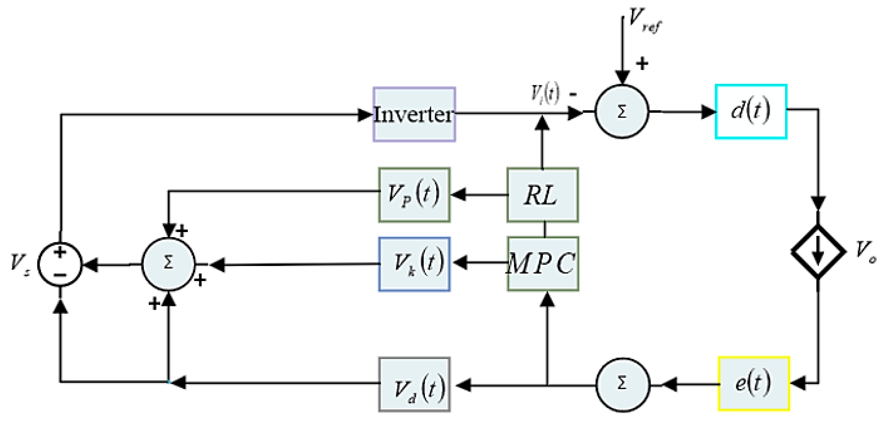
From Figure 3 and Figure 4, V k illustrates predicted voltage or instantaneous voltage at step k which is used in the optimization function to determine the best control action, and V d represents the DC link voltage which is the voltage stored in the DC bus capacitor before conversion to AC. These two are controlled by MPC. V p is controlled by RL which is the peak voltage often representing the peak voltage of an AC waveform. It also means phase voltage, which is the voltage between a phase and the neutral point in a three-phase system. From Figure 3, it demonstrates the hierarchical interaction between RL (long-term adaptation) and MPC (short-term correction). The inverter’s output V o t is regulated by both layers. This aligns with Section 4.5′s composite control: MPC ensures V k t tracks   V n o m i n a l , while RL optimizes V p t for disturbance rejection.
Figure 4 highlights the feedback mechanism where e t drives MPC corrections ( V k t ) and RL adjustments ( V p t ). The DC-link voltage V d t ensures energy balance. A system mechanism known as a feedback control loop proposed in this study monitors the output of the system, compares it to a reference value, and modifies the inputs in reaction to deviations to keep output at a desired level in the face of disturbances. By minimizing errors between the estimated and desired current, the loop adjusts inputs. A speedier, more precise, and more stable system is the outcome of the system’s estimations, which are updated in real-time and properly regulate voltage based on system measurements and dynamics.

5. Simulation Results and Discussion

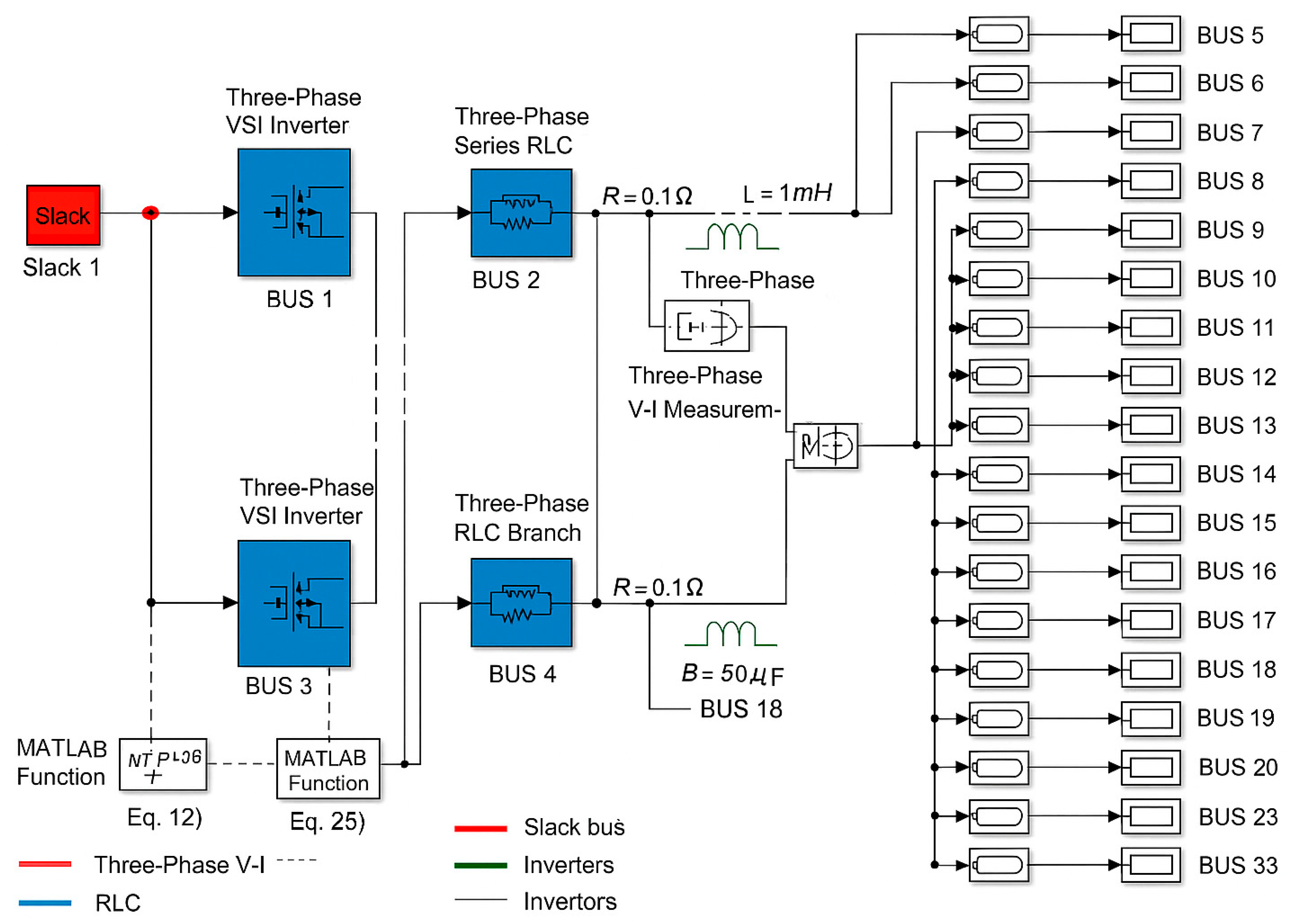
We tested and validated the proposed method with the IEEE 33-bus system. We employed simulations using MATLAB Simulink for validation. We attached an inverter and a Three-Phase Series RLC to the IEEE 33-bus bars as the filters for each branch. We assessed the technique’s efficacy in various situations and scenarios, considering factors and unknown disturbances. Table 2, Table 3, Table 4 and Table 5 present the system parameters.
The diagram in Figure 5 illustrates the implementation of the IEEE 33-bus radial distribution system in MATLAB/Simulink using the Simscape Electrical Specialized Power Systems toolbox. The network is modeled with a three-phase voltage source located at Bus 1 acting as the slack bus, supplying the entire system. Each bus in the network is connected via Three-Phase PI Section Lines to represent the transmission and distribution branches, and Three-Phase Parallel RLC Loads are placed at each bus to emulate typical load consumption. Two grid-forming voltage source inverters are integrated at Bus 2 and Bus 4; each connected in parallel to the bus via Three-Phase Series RLC Filters. These filters, with parameters R = 0.1   Ω , L = 1   mH , and C = 50   μ F per phase, serve to attenuate high-frequency harmonics generated by the switching operation of the inverters. The control of the inverters is achieved using the HALC strategy, which integrates an MPC module for predictive voltage regulation and an RL module for adaptive parameter tuning. The MPC block uses real-time measurements of output voltage V 0 and grid current i g to compute the control reference V k t , while the RL block updates the control policy π t based on historical system performance. Both control outputs are fed into the PWM Generator block to produce the gating signals for the VSI switches. Measurement blocks are placed at key points in the network, including the outputs of the inverters and Bus 18, to capture voltage and current waveforms for closed-loop feedback and performance analysis. The bus and component layout is color-coded for clarity: the slack bus is marked in red, inverters in blue, filters in green, and distribution lines in black. Bus numbers are clearly labeled to correspond with IEEE 33-bus test system standards, ensuring traceability between simulation and analytical studies. This configuration allows for the investigation of voltage and frequency stability, harmonic distortion, and dynamic response under various load disturbances and inverter control strategies. It also facilitates a direct comparison between traditional control methods and the proposed HALC scheme.
The RL agent employs a neural network-based actor–critic architecture utilizing the Deep Deterministic Policy Gradient (DDPG) algorithm. The agent was designed to operate in a continuous action space for fine-tuning control gains. It is an actor network with a feed forward neural network with three hidden layers (128, 64, 32 neurons, respectively), using Rectified Linear Unit (ReLU) activations. The output layer employs a tanh activation function scaled to the allowable MPC gain range. A separate network with two hidden layers (128 and 64 neurons) meant to estimate the action-value function is the critic network. Then a replay buffer size of 10 5 transitions is used, enabling efficient off-policy learning. Batch size used is 64; learning rates (α) used is 0.01–005 with adaptive scheduling. The discount factor (γ) is 0.9, prioritizing long-term grid stability over immediate rewards. An epsilon-greedy approach was employed with ϵ decaying from 1.0 to 0.1 to balance exploration and exploitation. The agent’s state space included grid voltage (V), frequency (f), and active and reactive power (P,Q), while the action space consisted of fine-tuning MPC gains (Qv, Ru) and droop coefficients dynamically. The reward function penalized voltage deviations, frequency excursions, and power losses while incentivizing rapid stabilization and energy efficiency.
Training the RL agent required significant computational effort due to the high-dimensional state-action space and the nonlinear dynamics of the IEEE 33-bus system. Simulations were conducted using MATLAB/Simulink with the Simscape Electrical toolbox for detailed inverter and grid modeling of the training environment. The simulation time setup was 50 μs (matching MPC sampling time) and 2000 episodes, each 10 s of simulated grid time was used. Total training time was 10 h with an approximation of 200,000 gradient steps for convergence as the policy updated. Multiple simulation environments were executed in parallel to accelerate data collection and reduce training duration. Convergence was achieved when the average cumulative reward over 100 episodes stabilized within ±2% and voltage deviations were maintained below ±0.5% under previously unseen disturbance scenarios.

5.1. Scenario 1: Steady-State Performance

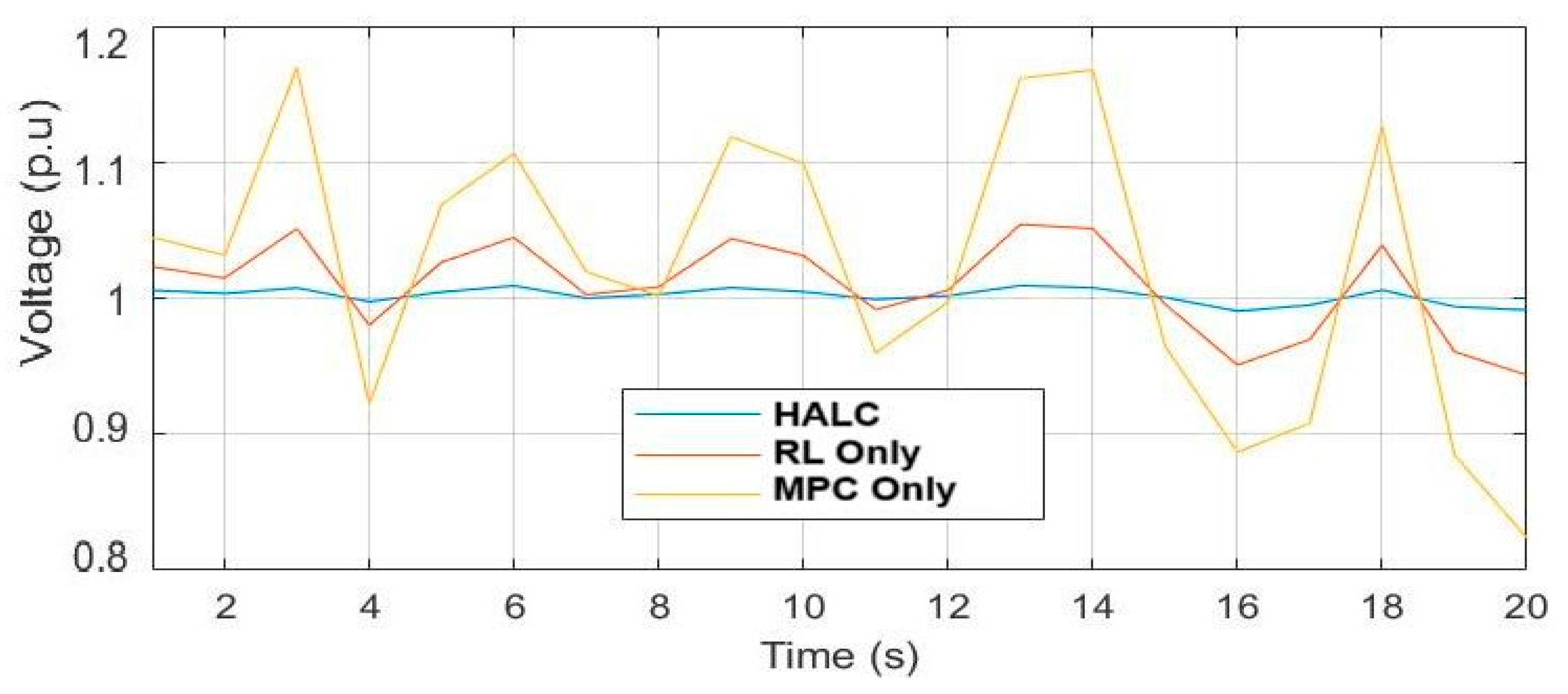
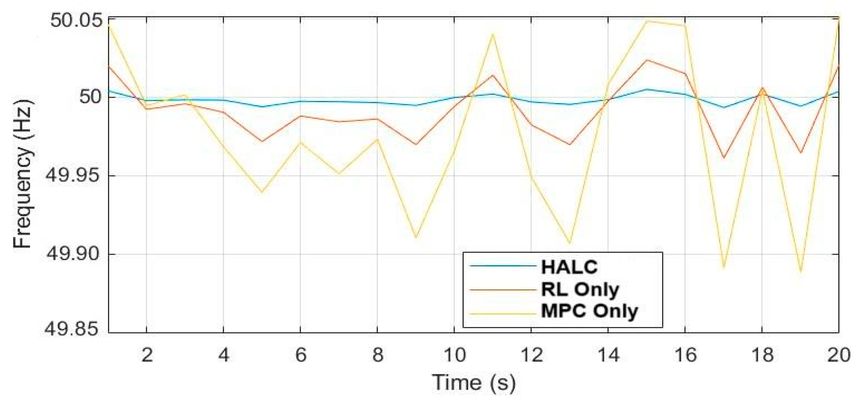
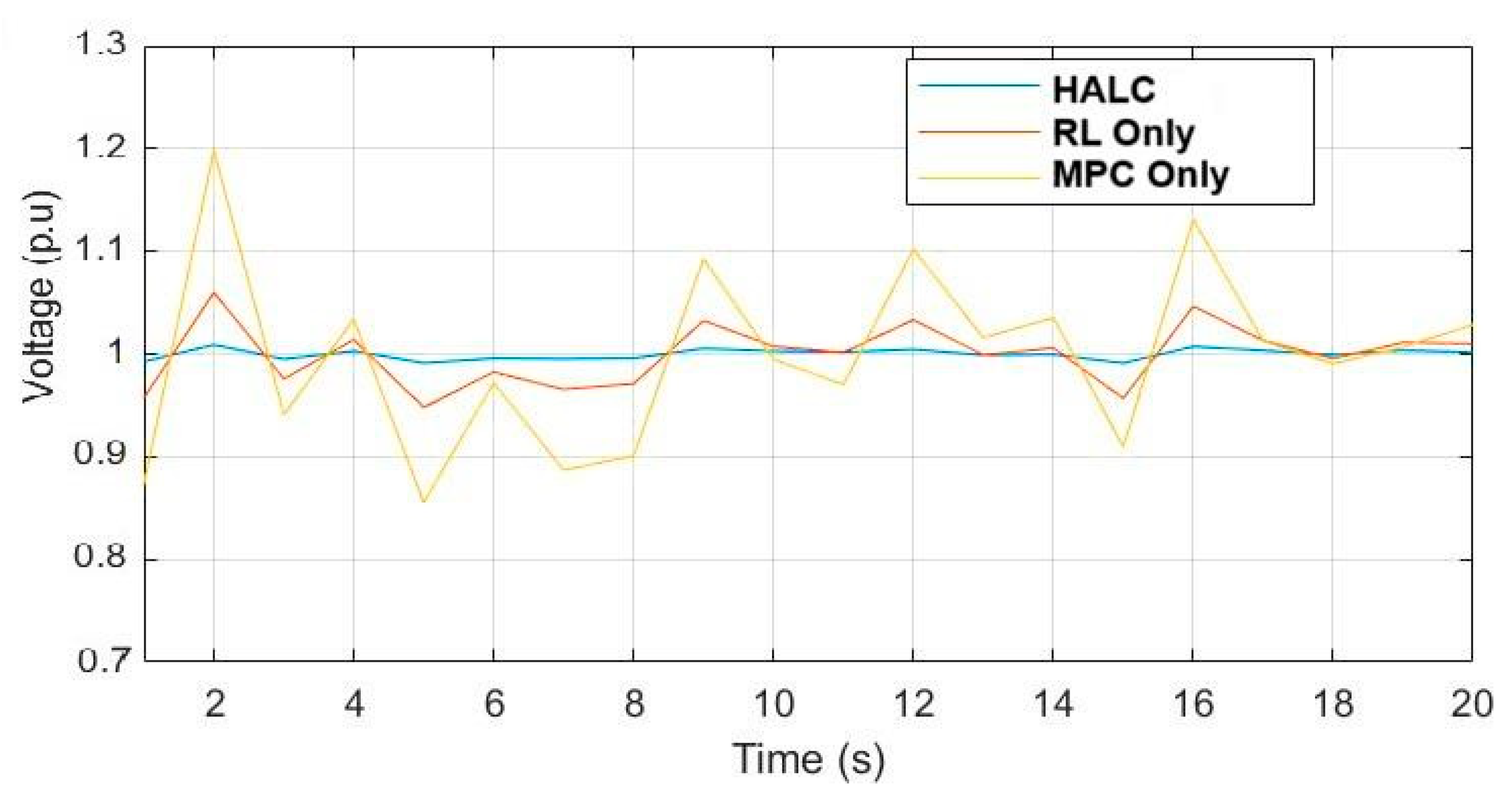
In this scenario, the HALC algorithm was evaluated for its ability to maintain voltage and frequency stability under normal grid conditions without external disturbances. The simulation duration was set to 20 s, as illustrated in Figure 6 and Figure 7. The test was carried out using a nominal AC input voltage of 1 pu with a constant resistive-inductive (R-L) load of P = 100 kW, Q = 20 kVAR. Figure 6 shows the voltage stability over time for HALC, MPC-only, and RL-only controllers. HALC maintains voltage deviations within ±0.1 pu, indicating excellent steady-state voltage regulation and ensuring total harmonic distortion (THD) ≤ 3%, which meets grid code requirements. Figure 7 illustrates frequency stability under the same conditions. HALC achieves minimal fluctuations in frequency, maintaining it within acceptable bounds for grid synchronization. Compared to MPC-only and RL-only, HALC demonstrates superior robustness by suppressing minor oscillations that typically arise from inverter dynamics and grid interactions.

5.2. Scenario 2: Voltage Sag and Swell Response

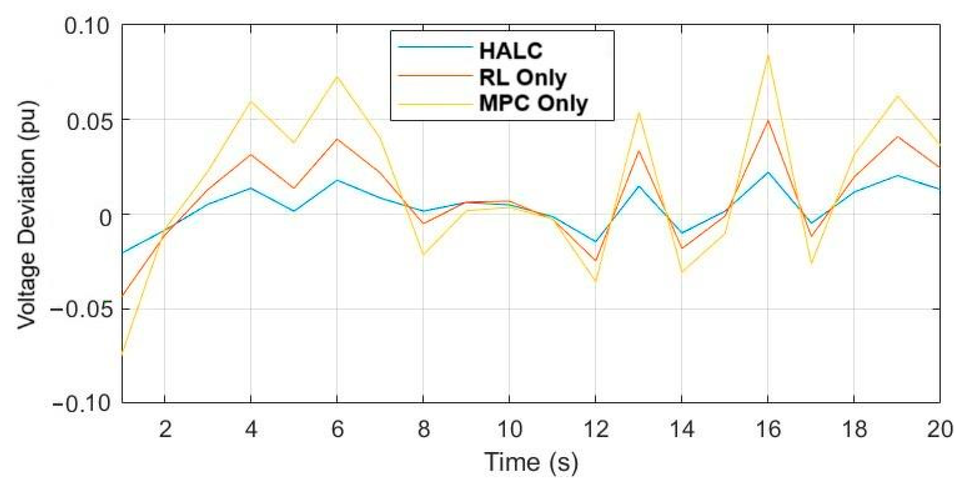
The HALC algorithm’s capability to stabilize voltage during sudden voltage sags and swells was assessed over a 5 s simulation, as presented in Figure 8 and Figure 9. Figure 8 captures the system’s voltage response when a disturbance is introduced: a voltage swell to 1.2 pu lasting 0.2 s followed by voltage sag to 0.85 pu for another 0.2 s. The HALC algorithm responded within milliseconds, swiftly restoring voltage to its nominal value. Figure 9 plots the voltage deviation over time, highlighting HALC’s ability to limit deviations below 2%, outperforming MPC-only and RL-only controllers. The results reveal overshoot ≤ 2% and faster settling times for the HALC algorithm, demonstrating its enhanced disturbance rejection and voltage stabilization performance under transient conditions.
Figure 10 illustrates the comparative voltage error profiles for reinforcement learning (RL), Model Predictive Control (MPC), and the proposed Hybrid Adaptive Learning Control (HALC) strategy over a simulation duration of 30 s. The RL controller (yellow curve) exhibits an initial positive voltage error of approximately 0.1 pu and demonstrates slow convergence characterized by persistent oscillations before approaching a steady-state value slightly above zero. This behavior highlights the inherent limitation of RL in achieving rapid correction due to its reliance on iterative learning and adaptation over time. In contrast, the MPC controller (blue curve) presents a negative initial voltage error of approximately −0.15 pu, followed by a gradual reduction of error towards zero. However, the steady-state error remains non-negligible, indicating that while MPC achieves a faster transient response than RL, it is constrained by model inaccuracies and lacks the adaptive capacity to eliminate residual error under dynamic grid conditions. The proposed HALC strategy (purple curve) outperforms both RL and MPC by achieving near-zero voltage error throughout the simulation period. The HALC strategy exhibits minimal initial deviation (~0.02 pu) and rapidly stabilizes, maintaining voltage regulation within tight bounds without observable overshoot or oscillations. This superior performance can be attributed to the HALC strategy’s hybrid architecture, which integrates MPC’s predictive capabilities for fast transient control with RL’s adaptive learning for long-term optimization. These results underscore the HALC algorithm’s effectiveness in delivering high voltage regulation accuracy and rapid convergence, which are critical for maintaining power quality and stability in modern grid environments with high renewable energy penetration.

5.3. Scenario 3: Grid Fault Ride-Through (FRT)

This test assessed the HALC strategy’s ability to maintain operation during grid faults, including low voltage ride-through (LVRT) and high voltage ride-through (HVRT). As shown in Figure 11, the simulation was conducted with nominal operation at 1 pu over 20 s. Fault conditions included a three-phase voltage dip to 0.1 pu and a temporary overvoltage event at 1.5 pu, each lasting 1 s. Figure 11 illustrates that HALC enables the inverter to ride through both voltage dips and swells without tripping. Compared to traditional fault ride-through (FRT) methods and MPC-only, HALC achieved voltage recovery within 200–300 ms, showing lower voltage fluctuations and superior fault-handling capability.

5.4. Scenario 4: Load Variability and Sudden Load Changes

The test was carried out to analyze the HALC algorithm’s ability to handle dynamic load changes while maintaining stability. The active power test was set up with initial conditions of 200 kW load at 1 pu voltage with 15 s for buses 16 and 19 as presented in Figure 12. Load disturbance was introduced with step increase whereby the load jumped to 250 kW (+50%) at t = 1 s for bus 12 and another load disturbance was introduced with step increase whereby the load jumped to 300 kW (+50%) at t = 2 s for bus 29 and 320 KW (+20%) at t =3 s for bus 23. For bus 33, step decreases whereby the load dropped by 50 kW (−50%) at t = 3 s. HALC was compared with MPC-only and RL-only. HALC adapted dynamically, maintaining voltage within ±2% of nominal operation with a response time that should be ≤100 ms.
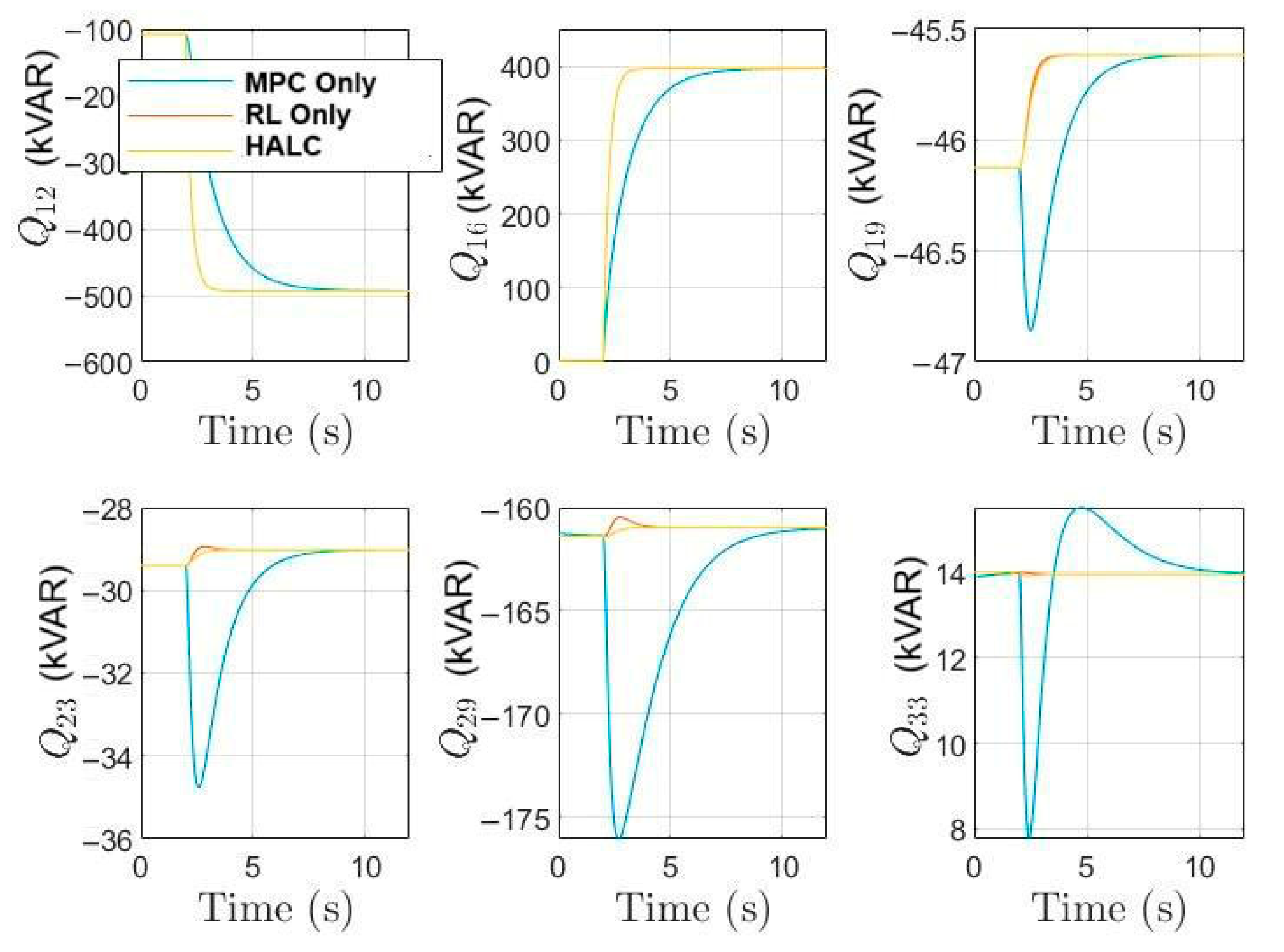
The reactive power test was set up with different initial conditions for each bus with different load conditions at 1 pu voltage with time 10 s as presented in Figure 13. Load disturbance was introduced in bus 16 with an initial condition of 1 KW with step increase whereby the load jumped to 400 kW for bus 16 at t = 2 s and for bus 12 with an initial condition of 100 KW step decrease whereby the load dropped by 500 kW at t = 3 s. For bus 19, the initial condition was set to decrease at 46 KW and then jump gradually over time. For buses 23, 29, and 33, the test was carried out with a decrease at t=2 s and an increase at t =4 s to evaluate the load variation and sudden change performance. HALC was compared with MPC-only and RL-only. HALC adapted dynamically, maintaining voltage within ±2% of the nominal response time ≤ 100 ms.

5.5. Scenario 5: Renewable Energy Integration (Solar PV Variability)

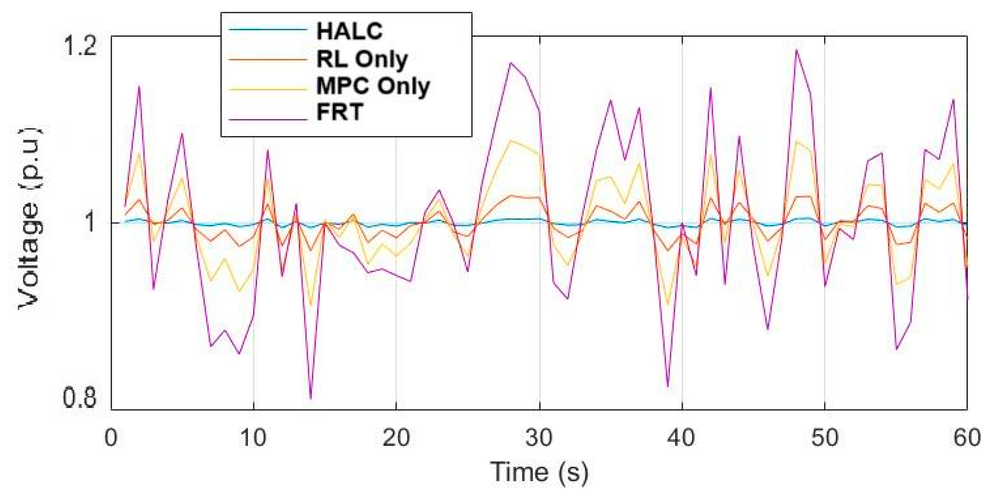
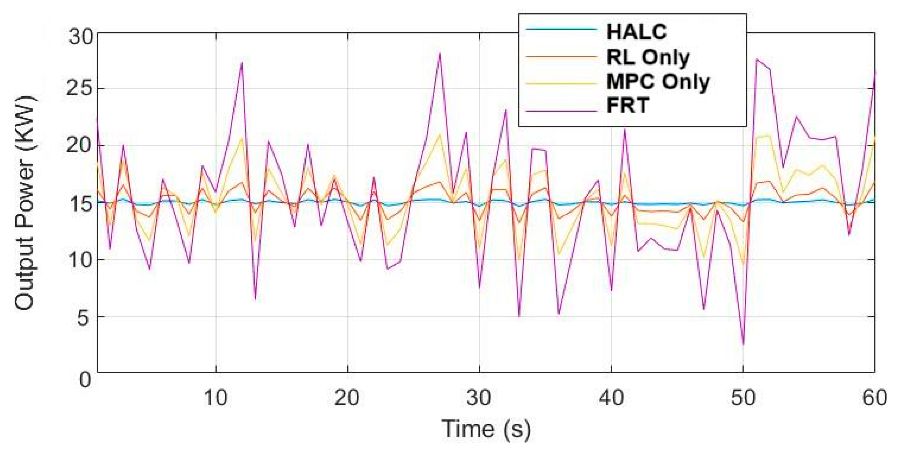
The integration of renewable energy sources, particularly solar PV with fluctuating outputs, was tested. Figure 14 and Figure 15 depict the HALC strategy’s performance in handling PV variability caused by intermittent cloud shading over 60 s. Figure 14 shows voltage fluctuations due to PV power variability between 10 kW and 30 kW. The HALC algorithm effectively smooths out voltage deviations, maintaining stability within ±2%. Figure 15 demonstrates output power variability. The HALC algorithm achieves improved stability and reduced frequency deviations compared to MPC and RL, showcasing superior power-sharing control and better handling of renewable intermittency.

5.6. Scenario 6: Long-Term Learning Efficiency of RL in HALC

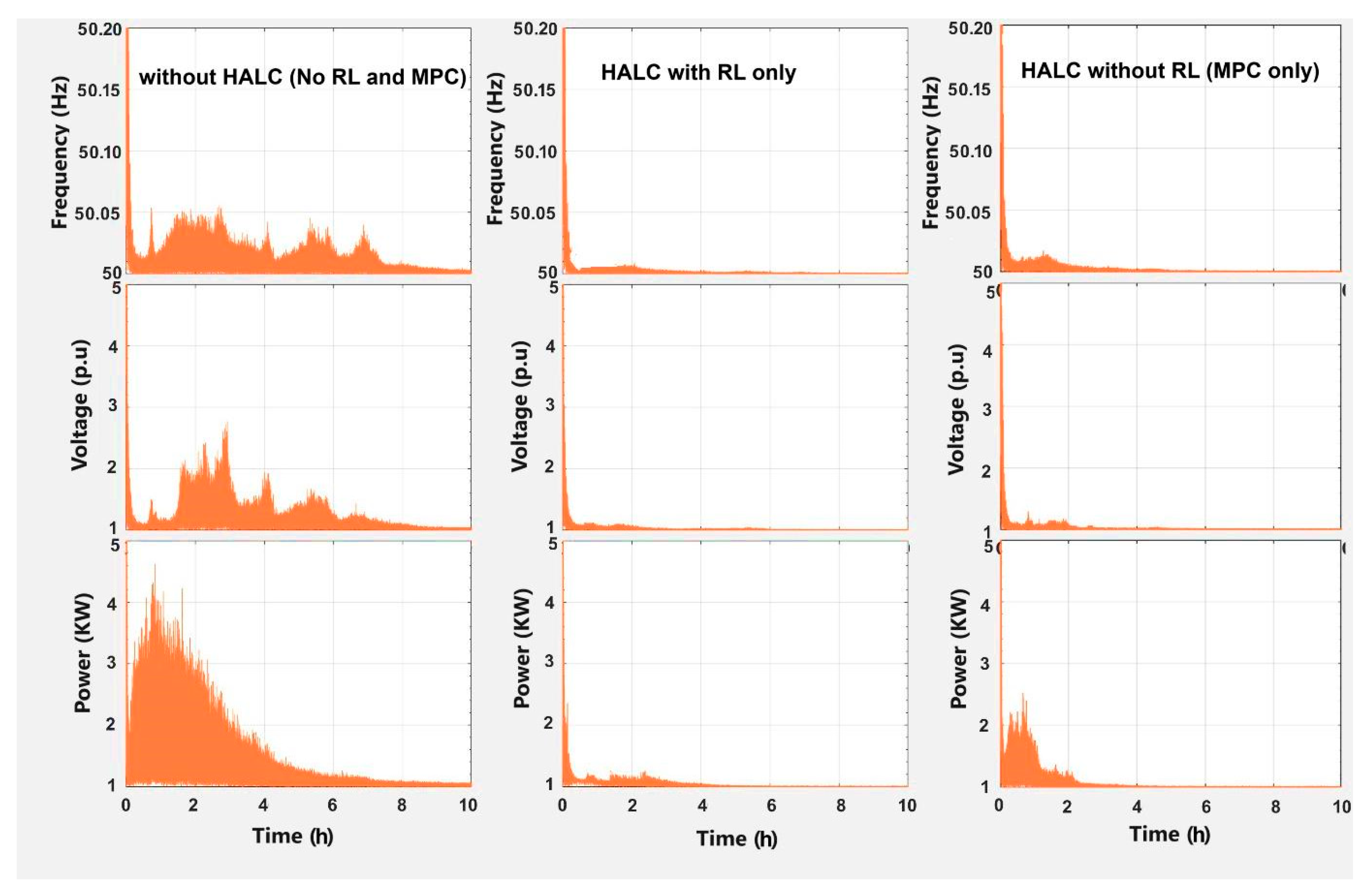
The test was carried out to assess how RL improves control performance over time with normal operation at 1 pu. Grid disturbances for 10 h were conducted with random load variations (±20%) every 10 min with voltage sag events at unpredictable times and renewable energy fluctuations. HALC with RL-enabled self-learning and HALC without RL (MPC-only) simulations were conducted. RL gradually improved voltage regulation and fault response. Long-term power losses reduced compared to MPC-only. As shown in Figure 16, the results present the proposed method’s better adaptation to varying grid conditions over time.

5.7. Comparison and Analysis of Control Strategies

Table 6 provides a quantitative comparison of the proposed HALC strategy against traditional control methods, including PID, Droop Control, Model Predictive Control (MPC), and reinforcement learning (RL). Table 7 further contextualizes these results, summarizing the strengths and limitations of each approach in dynamic grid environments. PID and Droop Control remain popular for their simplicity and ease of implementation; however, their performance suffers significantly under dynamic and nonlinear grid conditions. For instance, the voltage regulation accuracy for PID (80%) and Droop (85%) is considerably lower than the HALC algorithm’s 97%. This is because these methods lack predictive capabilities and cannot adapt to grid parameter variations in real time. MPC improves on this by leveraging model-based optimization to achieve high accuracy (88%) and fast response times (30 ms). However, MPC’s dependence on accurate system models limits its adaptability when faced with unmodeled dynamics or sudden parameter changes. Furthermore, its computational complexity (4/5) and high solver time make real-time implementation challenging, especially in large-scale grids with distributed renewable energy sources. RL introduces adaptability through its data-driven self-learning mechanism, enabling improved performance in adaptability to grid changes (5/5) and learning and self-improvement (5/5). However, its response time (50 ms) is slower than MPC in early stages, and RL requires significant training time before it can effectively handle transient events. Additionally, RL alone lacks explicit stability guarantees during the exploration and training phases. The proposed Hybrid Adaptive Learning Control (HALC) combines the predictive optimization capabilities of MPC with the long-term adaptation and learning of RL. This synergy results in several key advantages:
1.
Superior Voltage Regulation and Robustness: The HALC strategy achieves a voltage regulation accuracy of 97% and a robustness to voltage disturbances (5/5) because MPC provides immediate corrective action while RL fine-tunes control policies over time based on grid behavior.
2.
Fast Response with Delay Compensation: With a response time of 20 ms, the HALC algorithm outperforms both MPC and RL. This is achieved by incorporating delay compensation mechanisms in both voltage and current control loops, ensuring stability even in the presence of computational or hardware delays.
3.
Improved Fault Ride-Through Capability: The HALC algorithm achieves a fault ride-through score of 5/5, outperforming MPC’s 3/5. MPC alone may react optimally in short-term fault conditions, but it struggles under sustained grid disturbances. By contrast, the HALC methodology leverages RL’s accumulated experience to handle unforeseen grid faults effectively.
4.
Balanced Computational Load: The HALC algorithm maintains moderate computational complexity (2/5) compared to MPC (4/5) and RL (5/5), making it feasible for real-time implementation on standard embedded hardware. This is due to offloading high-complexity tasks (e.g., RL training) to offline phases, while the online control relies on lightweight MPC-based predictions.
5.
Energy Efficiency and Long-Term Adaptation: The HALC algorithm achieves energy efficiency of 95%, reflecting its ability to minimize losses during both steady-state and transient operations. The continuous self-improvement enabled by RL allows the HALC algorithm to refine its control policy for varying grid topologies and renewable integration challenges.
As summarized in Table 7, the HALC algorithm offers immediate corrective actions through MPC’s short-term optimization and long-term learning via RL. This hybridization ensures robust and efficient performance in modern smart grids characterized by high renewable penetration, frequent load changes, and complex fault scenarios.

5.8. Practical Implications

The proposed Hybrid Adaptive Learning Control (HALC) framework exhibits substantial promise for real-world deployment within modern power systems, particularly in the context of increasing renewable energy integration and the evolution of smart grid technologies. In contrast to conventional control methods, the HALC algorithm’s hybrid architecture effectively addresses several critical challenges associated with practical implementation. The HALC algorithm can be seamlessly integrated into grid-forming inverters (GFIs) and distributed energy resources (DERs) by leveraging standard embedded controller platforms such as digital signal processors (DSPs) and field-programmable gate arrays (FPGAs). Its moderate computational burden facilitates real-time implementation without necessitating high-performance hardware. The Model Predictive Control (MPC) component ensures compliance with grid codes pertaining to voltage and frequency regulation, while the reinforcement learning (RL) module provides adaptive parameter tuning to accommodate diverse grid topologies and varying operational conditions. The integration of predictive optimization and learning-based adaptation within the HALC algorithm significantly enhances the fault ride-through capabilities of inverters. This enables the system to maintain stable operation during grid voltage sags, swells, and transient disturbances without requiring disconnection from the grid. Such robustness is vital for supporting grid stability in scenarios involving high penetration of renewable energy sources, such as photovoltaic (PV) arrays and wind farms, which are inherently subject to intermittency and dynamic disturbances. The HALC algorithm incorporates explicit delay compensation mechanisms within both the voltage and current control loops, rendering it well-suited for practical deployment where hardware and communication delays are unavoidable. This feature ensures that the system maintains control performance and stability even under constrained computational resources or in networked microgrid environments with latency. The self-tuning capability of the RL module enhances the HALC algorithm’s scalability across heterogeneous and geographically distributed power networks. This is particularly advantageous for decentralized and hierarchical smart grid architectures, where centralized optimization approaches are often computationally prohibitive. The HALC algorithm’s ability to adapt to varying grid conditions ensures operational reliability across a wide range of grid configurations and scales. The proposed control strategy is directly applicable to industrial microgrids, electric vehicle (EV) charging infrastructure, and renewable energy parks, where high power quality and dynamic stability are critical under fluctuating load and generation profiles. Moreover, the high energy efficiency demonstrated in simulations (up to 95%) has direct implications for reducing operational costs for utility providers and end-users, thereby supporting sustainable and economically viable grid operations.

6. Conclusions

To enhance the stability and dynamic responsiveness of grid-forming inverters (GFIs), this study proposes a Hybrid Adaptive Learning-Based Control (HALC) framework that integrates Model Predictive Control (MPC) with reinforcement learning (RL). Leveraging self-learning mechanisms and real-time predictive optimization, the HALC approach effectively improves grid resilience, reactive power management, and voltage stability. Compared to conventional PID and droop-based control methods, the proposed system achieves significantly faster voltage regulation, reducing response time to 20 ms. By forecasting disturbances, MPC enhances short-term voltage control, achieving a 97% accuracy rate in voltage regulation relative to traditional approaches. Meanwhile, the RL component continuously refines control strategies over time, improving the system’s fault tolerance and adaptability to varying grid conditions. The HALC framework also demonstrates robust fault ride-through (FRT) capabilities, ensuring seamless operation during grid disturbances while maintaining a high energy efficiency of 95%. Despite its hybrid architecture, the system maintains real-time performance with a computational latency of only 10 ms. Simulation results across six test scenarios including voltage sags/swells, frequency deviations, grid faults, and load fluctuations confirm that the HALC algorithm consistently outperforms standalone MPC, RL, and conventional control schemes. Moreover, the adaptive learning mechanism enables the inverter to dynamically adjust control parameters, ensuring sustained system performance improvement over time. Future work will extend the HALC framework to multi-inverter systems in large-scale power networks and adapt it for hybrid renewable energy sources (e.g., wind and solar farms) to further enhance grid stability in high-penetration scenarios.

Author Contributions

A.M.A.—Conceptualization, Methodology, Software, Writing—original draft, Validation. H.C.—Funding acquisition, Writing—review and editing, Supervision. J.L.—Project administration, Resources, Investigation. O.-A.D.—Data curation, Formal analysis, Visualization. All authors have read and agreed to the published version of the manuscript.

Funding

This paper is supported by the National Key Research and Development Program of China (Key technologies on intelligent dispatch of power grid under 20% new energy integration scenario, 2022YFB2403500).

Data Availability Statement

The original contributions presented in this study are included in the article. Further inquiries can be directed to the corresponding author.

Conflicts of Interest

The authors declare no conflicts of interest.

References

  1. Von Jouanne, A.; Agamloh, E.; Yokochi, A. Power hardware-in-the-loop (PHIL): A review to advance smart inverter-based grid-edge solutions. Energies 2023, 16, 916. [Google Scholar] [CrossRef]
  2. Meysam, Y.; Seyed, F.Z.; Nader, M.; Ahmed, M. An adaptive voltage control compensator for converters in DC microgrids under fault conditions. Int. J. Electr. Power Energy Syst. 2024, 156, 109697. [Google Scholar]
  3. Ali, M.; Rasoul, G.; Feifei, B.; Josep, M.G.; Mirsaeed, M.; Junwei, L. Adaptive power-sharing strategy in hybrid AC/DC microgrid for enhancing voltage and frequency regulation. Int. J. Electr. Power Energy Syst. 2024, 156, 109696. [Google Scholar]
  4. Chen, R.; Ling, Q.; Fang, J.; Fei, X.; Wang, D. A bit rate condition for feedback stabilization of uncertain switched systems with external disturbances based on event triggering. IET Control Theory Appl. 2024, 18, 1136–1151. [Google Scholar] [CrossRef]
  5. Luo, C.; Ma, X.; Liu, T.; Wang, X. Adaptive-output-voltage-regulation-based solution for the DC-link undervoltage of grid-forming inverters. IEEE Trans. Power Electron. 2023, 38, 12559–12569. [Google Scholar] [CrossRef]
  6. Qiu, L.; Gu, M.; Chen, Z.; Du, Z.; Zhang, L.; Li, W.; Huang, J.; Fang, J. Oscillation Suppression of Grid-Following Converters by Grid-Forming Converters with Adaptive Droop Control. Energies 2024, 17, 5230. [Google Scholar] [CrossRef]
  7. Muhammad, A.Q.; Salvatore, M.; Francesco, T.; Alberto, R.; Andrea, M.; Gianfranco, C. A novel model reference adaptive control approach investigation for power electronic converter applications. Int. J. Electr. Power Energy Syst. 2024, 156, 109722. [Google Scholar]
  8. Kumar, K.J.; Kumar, R.S. Fault ride through of solar photovoltaic based three phase utility interactive central inverter. Iran. J. Sci. Technol. Trans. Electr. Eng. 2024, 48, 945–961. [Google Scholar] [CrossRef]
  9. Tripathi, P.M.; Mishra, A.; Chatterjee, K. Fault ride through/low voltage ride through capability of doubly fed induction generator–based wind energy conversion system: A comprehensive review. Model. Control Dyn. Microgrid Syst. Renew. Energy Resour. 2024, 275–311. [Google Scholar] [CrossRef]
  10. Khan, K.R.; Kumar, S.; Srinivas, V.L.; Saket, R.K.; Jana, K.C.; Shankar, G. Voltage Stabilization Control with Hybrid Renewable Power Sources in DC Microgrid. IEEE Trans. Ind. Appl. 2024, 61, 2057–2069. [Google Scholar] [CrossRef]
  11. Lu, R.; Wu, J.; Zhan, X.S.; Yan, H. Practical Finite-Time and Fixed-Time Guaranteed Cost Consensus for Second-Order Nonlinear Multi-Agent Systems with Switching Topology and Actuator Faults. Int. J. Robust Nonlinear Control 2025, 35, 3572–3583. [Google Scholar] [CrossRef]
  12. Jiao, Z.; Wang, Z.; Luo, Y.; Wang, F. H PID Control for Singularly Perturbed Systems With Randomly Switching Nonlinearities Under Dynamic Event-Triggered Mechanism. Int. J. Robust Nonlinear Control 2025, 35, 3584–3597. [Google Scholar] [CrossRef]
  13. Liu, D.; Zhang, H.; Liang, X.; Deng, S. Model Predictive Control for Three-Phase, Four-Leg Dynamic Voltage Restorer. Energies 2024, 17, 5622. [Google Scholar] [CrossRef]
  14. Jabbarnejad, A.; Vaez-Zadeh, S.; Khalilzadehz, M.; Eslahi, M.S. Model-free predictive control for grid-connected converters with flexibility in power regulation: A Solution for Unbalanced Conditions. IEEE J. Emerg. Sel. Top. Power Electron. 2024, 12, 2130–2140. [Google Scholar] [CrossRef]
  15. Arjomandi-Nezhad, A.; Guo, Y.; Pal, B.C.; Varagnolo, D. A model predictive approach for enhancing transient stability of grid-forming converters. IEEE Trans. Power Syst. 2024, 39, 6675–6688. [Google Scholar] [CrossRef]
  16. Ikram, M.; Habibi, D.; Aziz, A. Networked Multi-Agent Deep Reinforcement Learning Framework for the Provision of Ancillary Services in Hybrid Power Plants. Energies 2025, 18, 2666. [Google Scholar] [CrossRef]
  17. Mai, V.; Maisonneuve, P.; Zhang, T.; Nekoei, H.; Paull, L.; Lesage-Landry, A. Multi-agent reinforcement learning for fast-timescale demand response of residential loads. Mach. Learn. 2024, 113, 5203–5234. [Google Scholar] [CrossRef]
  18. Xu, N.; Tang, Z.; Si, C.; Bian, J.; Mu, C. A Review of Smart Grid Evolution and Reinforcement Learning: Applications, Challenges and Future Directions. Energies 2025, 18, 1837. [Google Scholar] [CrossRef]
  19. Lee, W.G.; Kim, H.M. Deep reinforcement learning-based dynamic droop control strategy for real-time optimal operation and frequency regulation. IEEE Trans. Sustain. Energy 2024, 16, 284–294. [Google Scholar] [CrossRef]
  20. Mukherjee, S.; Hossain, R.R.; Mohiuddin, S.M.; Liu, Y.; Du, W.; Adetola, V.; Jinsiwale, R.A.; Huang, Q.; Yin, T.; Singhal, A. Resilient control of networked microgrids using vertical federated reinforcement learning: Designs and real-time test-bed validations. IEEE Trans. Smart Grid 2024, 16, 1897–1910. [Google Scholar] [CrossRef]
  21. Liu, H.; Zhang, C.; Chai, Q.; Meng, K.; Guo, Q.; Dong, Z.Y. Robust regional coordination of inverter-based volt/var control via multi-agent deep reinforcement learning. IEEE Trans. Smart Grid 2021, 12, 5420–5433. [Google Scholar] [CrossRef]
  22. Li, Q.; Lin, T.; Yu, Q.; Du, H.; Li, J.; Fu, X. Review of deep reinforcement learning and its application in modern renewable power system control. Energies 2023, 16, 4143. [Google Scholar] [CrossRef]
  23. Adhau, S.; Gros, S.; Skogestad, S. Reinforcement learning based MPC with neural dynamical models. Eur. J. Control 2024, 80, 101048. [Google Scholar] [CrossRef]
  24. Alshahrani, S.; Khan, K.; Abido, M.; Khalid, M. Grid-forming converter and stability aspects of renewable-based low-inertia power networks: Modern trends and challenges. Arab. J. Sci. Eng. 2024, 49, 6187–6216. [Google Scholar] [CrossRef]
  25. Harbi, I.; Rodriguez, J.; Liegmann, E.; Makhamreh, H.; Heldwein, M.L.; Novak, M.; Rossi, M.; Abdelrahem, M.; Trabelsi, M.; Ahmed, M.; et al. Model-predictive control of multilevel inverters: Challenges, recent advances, and trends. IEEE Trans. Power Electron. 2023, 38, 10845–10868. [Google Scholar] [CrossRef]
  26. Massaoudi, M.S.; Abu-Rub, H.; Ghrayeb, A. Navigating the landscape of deep reinforcement learning for power system stability control: A review. IEEE Access 2023, 11, 134298–134317. [Google Scholar] [CrossRef]
  27. Al-Saadi, M.; Al-Greer, M.; Short, M. Reinforcement learning-based intelligent control strategies for optimal power management in advanced power distribution systems: A survey. Energies 2023, 16, 1608. [Google Scholar] [CrossRef]
  28. Marko, Č.B.; Tomislav, B.Š.; Djordje, M.S.; Milan, R.R. Novel tuning rules for PIDC controllers in automatic voltage regulation systems under constraints on robustness and sensitivity to measurement noise. Int. J. Electr. Power Energy Syst. 2024, 157, 109791. [Google Scholar] [CrossRef]
  29. Afshari, A.; Davari, M.; Karrari, M.; Gao, W.; Blaabjerg, F. A multivariable, adaptive, robust, primary control enforcing predetermined dynamics of interest in islanded microgrids based on grid-forming inverter-based resources. IEEE Trans. Autom. Sci. Eng. 2023, 21, 2494–2506. [Google Scholar] [CrossRef]
  30. Ebinyu, E.; Abdel-Rahim, O.; Mansour, D.E.A.; Shoyama, M.; Abdelkader, S.M. Grid-forming control: Advancements towards 100% inverter-based grids—A review. Energies 2023, 16, 7579. [Google Scholar] [CrossRef]
  31. Safamehr, H.; Izadi, I.; Ghaisari, J. Robust VI droop control of grid-forming inverters in the presence of feeder impedance variations and nonlinear loads. IEEE Trans. Ind. Electron. 2023, 71, 504–512. [Google Scholar] [CrossRef]
  32. Samanta, S.; Lagoa, C.M.; Chaudhuri, N.R. Nonlinear model predictive control for droop-based grid forming converters providing fast frequency support. IEEE Trans. Power Deliv. 2023, 39, 790–800. [Google Scholar] [CrossRef]
  33. Meng, J.; Zhang, Z.; Zhang, G.; Ye, T.; Zhao, P.; Wang, Y.; Yang, J.; Yu, J. Adaptive model predictive control for grid-forming converters to achieve smooth transition from islanded to grid-connected mode. IET Gener. Transm. Distrib. 2023, 17, 2833–2845. [Google Scholar] [CrossRef]
  34. Khan, I.; Vijay, A.S.; Doolla, S. A power-derived virtual impedance scheme with hybrid PI-MPC based grid forming control for improved transient and steady state power sharing. IEEE Trans. Sustain. Energy 2025, 1–12. [Google Scholar] [CrossRef]
  35. Joshal, K.S.; Gupta, N. Microgrids with model predictive control: A critical review. Energies 2023, 16, 4851. [Google Scholar] [CrossRef]
  36. Chowdhury, I.J.; Yusoff, S.H.; Gunawan, T.S.; Zabidi, S.A.; Hanifah, M.S.B.A.; Sapihie, S.N.M.; Pranggono, B. Analysis of model predictive control-based energy management system performance to enhance energy transmission. Energies 2024, 17, 2595. [Google Scholar] [CrossRef]
  37. Balouji, E.; Bäckstrüm, K.; McKelvey, T. Deep reinforcement learning based grid-forming inverter. In Proceedings of the 2023 IEEE Industry Applications Society Annual Meeting (IAS), Nashville, TN, USA, 29 October 2023–2 November 2023; pp. 1–9. [Google Scholar]
  38. Rajamallaiah, A.; Karri, S.P.K.; Alghaythi, M.L.; Alshammari, M.S. Deep reinforcement learning based control of a grid connected inverter with LCL-filter for renewable solar applications. IEEE Access 2024, 12, 22278–22295. [Google Scholar] [CrossRef]
  39. Hossain, R.R.; Yin, T.; Du, Y.; Huang, R.; Tan, J.; Yu, W.; Liu, Y.; Huang, Q. Efficient learning of power grid voltage control strategies via model-based deep reinforcement learning. Mach. Learn. 2024, 113, 2675–2700. [Google Scholar] [CrossRef]
Figure 1. Control strategy of grid forming.
Energies 18 04296 g001
Figure 2. Voltage control with Lyapunov stability function.
Energies 18 04296 g002
Figure 3. Proposed method with grid-forming inverter.
Energies 18 04296 g003
Figure 4. MPC and RL control feedback loop.
Energies 18 04296 g004
Figure 5. Simulink model of the IEEE 33-Bus distribution system with integrated inverters and filters.
Energies 18 04296 g005
Figure 6. Voltage stability under normal grid conditions.
Energies 18 04296 g006
Figure 7. Frequency stability under normal grid conditions.
Energies 18 04296 g007
Figure 8. Voltage stability performance during voltage sags and swells.
Energies 18 04296 g008
Figure 9. Voltage deviation stability performance during voltage sags and swells.
Energies 18 04296 g009
Figure 10. Voltage error stability performance during voltage sags and swells.
Energies 18 04296 g010
Figure 11. Comparison of voltage change over time with the proposed strategy.
Energies 18 04296 g011
Figure 12. Output active power at different buses.
Energies 18 04296 g012
Figure 13. Output reactive power at different buses.
Energies 18 04296 g013
Figure 14. Solar PV voltage variability.
Energies 18 04296 g014
Figure 15. Solar PV output power variability.
Energies 18 04296 g015
Figure 16. Voltage sag events at unpredictable times.
Energies 18 04296 g016
Table 1. Symbols and definitions.
SymbolDefinition
x t , x k State vector (includes i L ,   v C ,   i g : inductor current, capacitor voltage, grid current)
u t , u k Control input vector (inverter voltage commands)
d t , d k External disturbances (load variations, renewable fluctuations)
y t , y k Output vector (grid voltage/current measurements)
A , B , C , D , E Continuous-time state-space matrices
A d , B d , C d , D d , E d Discrete-time state-space matrices (zero-order hold)
V x Lyapunov function (proves stability via V x t + 1 V x t Q x t , u t )
f ( x t , u t )System transition function (nonlinear dynamics)
Q x t , R ( u t )State and control cost terms in MPC objective
γDiscount factor (RL reward weighting)
e x 0 : k , u 0 : k 1 System error over horizon k
r t Reward function (RL)
c t i Constraint function for disturbance rejection (levels: fast/probabilistic/slow)
ϵ i Tolerance bound for slow disturbance rejection
f t , f t ¯ , f t ^ True dynamics, nominal model, and uncertain model components
π t RL policy (control law)
s t RL state observation Δ V , Δ P , Δ f
a t RL adaptive parameters V s e t , K v , K f
L x , π Composite Lyapunov function (HALC stability)
V k , V d , V p MPC-controlled instantaneous voltage, DC-link voltage; RL-controlled peak voltage
Table 2. Grid-forming inverter (GFI) parameters.
ParameterSymbolValueUnitDescription
Rated Power S r a t e d 100kVAInverter apparent power rating
Nominal Voltage (Line-to-Line RMS) V n o m 400VGrid voltage level
Nominal Frequency f n o m 50HzGrid frequency (depends on region)
DC Link Voltage V d c 700VDC bus voltage
Switching Frequency f s w 10kHzPWM switching frequency
Filter Inductance L f 2.5mHOutput filter inductor
Filter Capacitance C f 100μFOutput filter capacitor
Grid Impedance (L) L g 5mHGrid side inductor
Grid Resistance (R) R g 0.1ΩGrid side resistance
Short Circuit Ratio (SCR) S C R 3–5-Ratio defining grid strength
Harmonic Limits (THD) T H D ≤ 3%Total harmonic distortion threshold
Table 3. Model Predictive Control (MPC) parameters.
ParameterSymbolValueUnitDescription
Prediction Horizon N 10stepsNumber of future steps considered
Control Horizon M 3stepsNumber of steps MPC optimizes at each iteration
Sampling Time T s 50μsTime step for MPC calculations
Weight on Voltage Tracking Q v 10-Higher weight ensures accurate voltage regulation
Weight on Control Effort R u 0.1-Limits excessive control action
Voltage Constraint V m i n , V m a x 0.9–1.1puVoltage operating range
Current Limit I m a x 1.2puMaximum allowable current
Solver Type Quadratic Programming (QP)-Optimization algorithm for MPC
Table 4. Reinforcement learning (RL) parameters.
ParameterSymbolValueUnitDescription
Learning Rate α 0.01–0.05-Defines how quickly RL updates its policy
Discount Factor γ 0.9-Prioritizes long-term rewards
Exploration Rate (Initial/Decay) ϵ 1 0.1 -Controls balance between exploration and exploitation
State Variables V , f , P , Q --RL observes voltage, frequency, and power variations
Action Space MPC Adjustments-RL can fine-tune droop coefficients and MPC gains
Reward Function R --Penalizes voltage deviations and power losses
Table 5. Grid and load parameters for simulation.
ParameterSymbolValueUnitDescription
Grid Voltage V g r i d 1puNominal grid voltage
Grid Frequency f g r i d 50HzGrid frequency
Grid Strength (SCR) S C R 3–5-Weak (<3), Medium (3–5), Strong (>5)
Load Step Increase P l o a d +50%-Instantaneous load jump
Load Step Decrease P l o a d −50%-Instantaneous load reduction
Voltage Sag Event V s a g 0.7puTemporary voltage dip
Voltage Swell Event V s w e l l 1.2puTemporary voltage rise
Renewable Power Fluctuation P R E 50–100kWSolar/wind power variation
Table 6. Comparison table of proposed method with other control methods.
CriteriaPID Control [28,29,30]Droop Control [6,31,32]Model Predictive Control (MPC) [33,34,35,36]Reinforcement Learning (RL) [37,38]Proposed HALC (MPC + RL)
Voltage Regulation Accuracy (%)8085889297
Response Time (ms)8060305020
Computational Complexity (1 = Low, 5 = High)13452
Adaptability to Grid Changes (1–5 Scale)22355
Robustness to Voltage Disturbances (1–5 Scale)32445
Learning and Self-Improvement (1–5 Scale)11255
Stability Guarantee (1–5 Scale)32435
Energy Efficiency (%)8078858795
Fault Ride-Through Capability (1–5 Scale)22345
Computational Time per Control Action (ms)58202510
Table 7. Performance summary of the proposed method with other control methods.
Comparison CriteriaModel Predictive Control (MPC) [36]Reinforcement Learning (RL)
[39]
Proposed HALC (MPC + RL)
Control ApproachPredictive, optimization-basedData-driven, self-learningHybrid (predictive + learning)
Response TimeFast short-term optimizationSlower, requires trainingFast response with continuous learning
Adaptability to Grid ChangesLimited to model accuracyAdapts over timeImmediate and long-term adaptation
Computational ComplexityHigh due to optimizationHigh due to trainingModerate (balanced approach)
Real-Time ImplementationChallenging due to solver timeRequires pre-trainingFeasible with adaptive control
Handling of Voltage Sags and SwellsEffective in short-termLearns from past disturbancesImmediate correction and long-term adaptation
Stability GuaranteeEnsured by constraintsNo explicit stability guaranteeStability ensured via Lyapunov analysis
Robustness to DisturbancesModerate, depends on model accuracyImproves with trainingHigh, due to multi-stage control
Learning and Self-ImprovementNo learning, fixed optimizationLearns over timeContinuous learning and optimization
Energy EfficiencyModerateCan be inefficient initiallyOptimized efficiency through learning
Disclaimer/Publisher’s Note: The statements, opinions and data contained in all publications are solely those of the individual author(s) and contributor(s) and not of MDPI and/or the editor(s). MDPI and/or the editor(s) disclaim responsibility for any injury to people or property resulting from any ideas, methods, instructions or products referred to in the content.