Abstract
The vortex generator is extensively utilized to enhance the air-side flow and heat transfer in compact heat exchangers, attributed to its high efficiency and low friction factor. This paper contains an innovative design of biomimetic vortex generators (BVGs), characterized by a distinct variable curvature and orientation. The curvatures and orientations, serving as key parameters for this innovative design, were collaboratively optimized using a combination of the response surface method and the non-dominated sorting genetic algorithm II, while the friction factor and Colburn factor serve as objective functions. The research findings indicate that the use of BVGs significantly reduces the friction factor, and the optimal curvature parameters for various orientations have been determined. The enhanced heat transfer mechanism associated with BVGs is attributed to their capacity to generate multiple longitudinal vortex structures downstream, with analogous secondary flow structures forming across different orientations. A comprehensive evaluation metric reveals that BVGs achieve an improvement exceeding 50% in performance compared to other high-performance vortex generators. These findings introduce an entirely novel configuration for vortex generators, which is anticipated to significantly advance the development of flow and heat transfer enhancement in compact heat exchangers.
1. Introduction
In compact finned tube heat exchangers, the thermal friction factor on the air side constitutes approximately 70% to 90% of the total thermal friction factor [1]. Consequently, augmenting the heat transfer efficiency on the air side is imperative for enhancing the overall efficiency of the heat exchanger. Vortex generators (VGs) have been shown to markedly improve heat transfer performance under a low Reynolds number, and their relatively small structural size can substantially decrease the friction factor. Therefore, VGs are considered the most effective turbulence-inducing elements for optimizing the performance of air side channels in compact heat exchangers.
The traditional structure of VGs predominantly comprises geometric shapes such as rectangles, triangles, and trapezoids [2]. In recent years, researchers have introduced novel configurations, including X-truss VGs [3] and conic VGs [4], which have demonstrated efficacy in enhancing heat transfer. Compared to these specialized structures, the modification of traditional VGs into curved VGs (CVGs) offers a more straightforward manufacturing process. The additional secondary flow induced by CVGs further augments heat transfer [5], while their streamlined curved design significantly reduces the friction factor within the flow channel [6,7]. Additionally, perforating VGs with holes has been considered a viable strategy to decrease the flow friction factor. For example, Modi et al. [8] observed that VGs with perforations consistently reduced the flow friction factor, with a configuration featuring six holes achieving a friction factor reduction of 13.81%. Studies on curved trapezoidal VGs have shown that a design incorporating six holes can reduce the friction factor by 8.1% [9]. A subsequent investigation indicated that the implementation of VGs with surface perforations is advantageous, particularly in scenarios where the Reynolds number exceeds 120 [10]. Furthermore, as the diameter of the holes decreases, both the friction factor and the Nusselt number increase [11]. This finding suggests that further exploration of various geometric parameters of VGs could enhance heat transfer efficiency and reduce the flow friction factor [12,13]. Notably, when the attack angle of VGs is set at 30° or 60°, the flow channel demonstrates optimal comprehensive evaluation metrics [14]. Some researchers further pointed out that in order to improve the overall performance, the attack angle should not be less than 30° [15]. Conversely, an attack angle of 15° yields the most favorable convective heat transfer performance [16,17]. Additionally, Sharma et al. [18] conducted an extensive study on the dimensionless base width, height, and angle of attack of VGs, identifying their optimal configuration. Similar parametric analyses have examined various angles of attack and pitch ratios [19]. The optimal VG configuration achieved a 3.87% reduction in the friction factor and a 4.11% increase in the Nusselt number [20]. Research on triangular VGs has shown that an aspect ratio of 1.75 results in superior thermal and fluid dynamic performance. Furthermore, a transverse pitch of 1.24 leads to a 6.5% increase in the average Nusselt number [21]. Moreover, there exists an optimal vertical position that maximizes the intensity of longitudinal vortices and enhances heat transfer [22]. From a comprehensive evaluation standpoint, the optimal parameters are identified as follows: angle of attack α = 40.2°, longitudinal spacing C = 3 mm, and lateral spacing A = 3 mm [23]. Dogan et al. [24] conducted a study on the effects of longitudinal and transverse pitch ratios, concluding that a transverse pitch ratio of 0.16 and a longitudinal pitch ratio of 1.5 resulted in the maximum thermal enhancement coefficient for the VGs flow channel.
In recent years, the emulation of structural characteristics observed in animals, plants, and natural phenomena to develop various biomimetic heat-enhancing structures has garnered significant attention from researchers. For example, inspired by the reduced-friction structure of fish, specialized rib-like surfaces have been engineered to enhance cooling in fuel cells [25]. Similarly, wing-like structures modeled after dolphin skin have been shown to effectively reduce drag and improve the lift-to-drag ratio [26]. Additionally, radiators inspired by the structural features of dragonfly wings [27] and sunflower leaves [28] have been developed to significantly enhance cooling efficiency by increasing fluid turbulence and optimizing airflow channels. Furthermore, innovative radiator designs inspired by the bionic form of sand dunes, characterized by their crescent-shaped design capable of inducing strong downstream secondary flows, have found extensive application in spacecraft engineering [29]. The design of bionic VGs, which create complex secondary flow structures to enhance heat transfer and achieve efficient drag reduction, is regarded as a promising strategy. For instance, Niu et al. [30] incorporated a bionic beak-like structure into the design of VGs, resulting in a substantial enhancement of the overall heat transfer performance of the novel bionic configuration. Notably, when the inclination angle is adjusted to 24°, there is a 47.09% reduction in the flow friction factor.
In general, an increase in heat transfer is frequently associated with a substantial rise in the flow friction factor. To address these challenges, researchers commonly employ the response surface method (RSM) in conjunction with multi-objective genetic algorithms (MOGAs) to derive Pareto optimal solutions. For example, Gonul et al. [31] conducted multi-objective optimization studies using the RSM to investigate the effects of various parameters of triangular VGs on heat transfer and pressure loss in heat exchangers. Similarly, Hu et al. [32] utilized MOGA to optimize the layout of VGs, employing the Pareto optimal strategy to determine the optimal lateral spacing. Furthermore, Li et al. [33] compared the optimization processes of traditional genetic algorithms with three enhanced genetic algorithms, identifying optimal values for parameters such as the installation angle, angle between vertices, vertex distance, and inlet velocity. The predictive accuracy of the RSM is crucial for ensuring the efficacy of the optimization design. Sharma et al. [34] demonstrated in their study that employing the RSM and artificial neural networks as inputs for the genetic algorithm can constrain the deviation between predicted and target data to within ±3%. A similar conclusion was reached by Xie et al. [35], who also reported high prediction accuracy using both neural networks and RSM. Although the literature does mention the use of RSM, artificial neural networks [36], the Taguchi method [37], or topology optimization [38] independently for predicting the thermal and hydraulic performance of the VG channel or for optimizing VGs’ structural parameters, such approaches are relatively uncommon.
This study presents a novel design for a biomimetic vortex generator featuring variable curvature and orientation, aimed at enhancing the flow and heat transfer performance of air-side flow channels in compact finned tube heat exchangers. A collaborative optimization approach was carried out using the response surface methodology with the non-dominated sorting genetic algorithm II. The findings offer significant insights into improving the performance of air-side flow channels in compact finned tube heat exchangers and optimizing the design of biomimetic vortex generators.
2. Description of the Model
2.1. Physical Model
Figure 1a illustrates the three-dimensional computational model of the compact fin-and-tube heat exchanger employed for the optimization studies in this paper. The present case study is taken from Modi et al. [8] for further validating the numerical model. This heat exchanger comprises four rows of inline circular tubes, with transverse and longitudinal spacings between adjacent tubes measuring S1 = 22 mm and S2 = 25.4 mm, respectively, and a tube diameter of D = 10.55 mm. The shaded region in the figure delineates the computational domain. Air with constant physical properties flows in from the left and exits on the right. An extension section is added in the downstream region of the flow channel to prevent outlet backflow, with a length set to 30D. Periodic boundary conditions are applied to the upper and lower surfaces of the computational domain, while symmetric boundary conditions are imposed on the left and right sides. In the compact fin-and-tube heat exchanger, significant flow separation occurs at the rear of the tubes, leading to reduced heat transfer performance. Consequently, VGs are installed at the rear of the tubes in two orientations: Common-Flow-Down (CFD) and Common-Flow-Up (CFU), which are, respectively, named as the D-Type and U-Type. The spacing between adjacent fins in the heat exchanger is Tp = 5.25 mm, as depicted in Figure 1b.
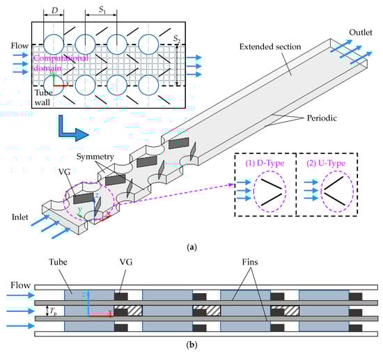
Figure 1.
Schematic diagram of compact fin-and-tube heat exchanger model: (a) computational model; (b) fin spacing.
Figure 2a depicts the installation positions and specific dimensional parameters of the VGs within the two orientations. For instance, considering the flat vortex generators (flat VGs, FVGs), the chord length is specified as l, the height is h, and the angle of attack is β. The position of the midpoint of the vortex generator is maintained constant, with the distance from the boundary and the center of the tube denoted as c. The FVGs function as the control group for subsequent analysis and comparison. Due to the typically negligible thickness of vortex generators, they are modeled as zero-thickness elements in this study. Drawing inspiration from the flight mechanics of seagulls, which adjust their elbow joints to modify their wing shape in response to gust disturbances, a biomimetic vortex generator with variable curvature and orientation—referred to as the Seagull-Inspired Curved Vortex Generator (SCVG)—was developed, as depicted in Figure 2b. The curved length is represented by d, and the curvature δ is defined as the ratio d/l, with δ = 0 corresponding to the initial design. Detailed structural parameters are provided in Table 1. These configurations are categorized as D1–D4 and U1–U4, based on their distinct variable curvature and orientation, as illustrated in Figure 2c.
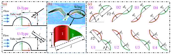
Figure 2.
Schematic diagram of the Seagull-Inspired Curved Vortex Generator: (a) installation location of VGs; (b) bionic prototype; (c) distinct configurations.

Table 1.
Geometric parameters of VGs.
2.2. Governing Equations and Boundary Conditions
In the present investigation, the Reynolds number indicates a laminar flow regime. Nonetheless, the configuration of vortex generators is expected to disturb the fluid, leading to the formation of vortex structures. Prior research has validated the suitability of employing turbulence models in numerical simulations, specifically the RNG k − ε turbulence model [9,18], the SST k − ω turbulence model [15,19], and the Realizable k − ε turbulence model [11]. These studies have confirmed the applicability of turbulence equations, and the continuity, momentum, energy, and turbulence transport equations are comprehensively detailed below.
The continuity equation is as follows [39]:
The momentum equation is as follows [39]:
where
μt is turbulent viscosity.
In the numerical solution of this study, the Realizable k − ε turbulence model was employed, and the turbulent kinetic energy equation (k) is as follows [11]:
The turbulent dissipation rate equation (ε) is as follows [11]:
where C1 = Max [0.43, η/(η + 5)], η = Sk/ε, S = (2 SijSij)0.5, Gk represents the turbulent kinetic energy generated by the mean velocity gradient, Gb represents the turbulent kinetic energy generated by buoyancy, and YM denotes the contribution of fluctuating expansion in compressible turbulence to the overall dissipation rate. C2 = 1.9 and Cε = 1.44 are constant values. σk = 1.0 and σε = 1.2 are the turbulent Prandtl numbers for k and ω, respectively.
The energy equation is as follows [39]:
The boundary conditions of the numerical simulation are as follows:
Velocity inlet: u = uin, v = ω = 0, T = Tin = 300 K;
Constant temperature surface of tube wall: T = Tw = 350 K;
Periodic boundary conditions at the bottom and top wall: uup = udown, Tup = Tdown.
The surface of the vortex generator is characterized by a no-slip boundary condition. It is assumed that the air behaves as an incompressible fluid with constant physical properties. The finite volume method is employed to discretize the governing equations. In the numerical solution process, the COUPLE algorithm is implemented to address the coupling of pressure and velocity. The convection term is discretized using the second-order upwind scheme, and the diffusion term is discretized using the central difference method. The convergence criterion for the numerical solution requires that the continuity residual of the velocity component be less than 1.0 × 10⁻⁵, and the energy residual be less than 1.0 × 10⁻⁶.
The vortex generator’s surface is defined by a no-slip boundary condition, assuming the air acts as an incompressible fluid with unchanging physical properties. The governing equations are discretized using the finite volume method. During the numerical solution process, the COUPLE algorithm is used to handle the pressure and velocity coupling. For the convection term, a second-order upwind scheme is employed, whereas the diffusion term is discretized with the central difference method. The numerical solution’s convergence criterion demands that the velocity component’s continuity residual be below 1.0 × 10⁻⁵, and the energy residual be under 1.0 × 10⁻⁶.
2.3. Parameter Definitions
The Reynolds number Re is defined as follows [39]:
The Colburn factor j is defined as follows [8]:
where h is the convective heat transfer coefficient of the heating surface which depends on the average heat flux q and the logarithmic average temperature difference Δtm between the heating surface and the fluid, namely as follows [39]:
The Nusselt number Nu is defined as follows [39]:
where λ is the thermal conductivity of the air.
The friction factor f is defined as follows [39]:
The comprehensive evaluation metric is defined as follows [8]:
The expression of the vorticity Ω is defined as follows [5]:
where
where e is a small positive number. A and B are the eigenvalues of the velocity gradient, where A is referred to as a symmetric tensor and B as an antisymmetric tensor. The symbol ΔV represents the velocity gradient matrix in the x, y, and z directions, while ΔVT is its transpose matrix.
2.4. Grid Independence Test and Validation of Numerical Results
A grid independence test was performed utilizing a model of the flat vortex generator arranged in a D-type configuration. The test employed varying numbers of grid cells: 502,945; 659,626; 883,569; 1,326,813; and 1,861,102. The Colburn factor (j) and friction factor (f) of the flow channel exhibited variations corresponding to the number of grids, as illustrated in Figure 3. It was observed that when the grid number exceeded 1,326,813, the rates of change in j and f were minimal, amounting to 1.34% and 0.1%, respectively. Consequently, to balance computational accuracy and efficiency, a grid cell count of 1,326,813 was selected for subsequent numerical solution.
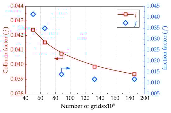
Figure 3.
j and f change with the number of grids.
As illustrated in Figure 4, the flow and heat transfer performance within the fin–tube heat exchanger channel varies in the absence of vortex generators, as noted in the literature and supported by the Realizable k-ε model used in this study. According to the figure, increasing the Reynolds number (Re) from 400 to 800 results in the average Nusselt number (Nu) and the pressure drop (Δp) of the channel flow showing trends that align with those reported in the reference [8]. These results are in close agreement with the literature, thus reinforcing the reliability of the numerical solution process.
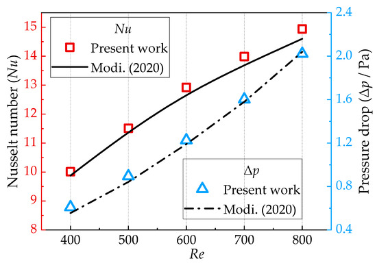
Figure 4.
Model verification.
3. Methodology
3.1. Multi-Objective Optimization Process
The primary aim of optimizing the SCVG structure is to minimize the pressure drop (Δp) at both the inlet and outlet, thereby reducing the flow friction factor within the channel; concurrently, the goal is to decrease the logarithmic mean temperature difference (Δtm) between the heating surface and the fluid, ultimately enhancing the convective heat transfer performance. The optimization research methodology employed in this study is illustrated in Figure 5, with the following key steps: (1) Identification of design variables, construction of the physical model, and grid discretization. (2) Specification of boundary conditions and initialization, followed by solving the governing equations and assessing convergence criteria. (3) Evaluation of the variation in convective heat transfer performance relative to design variables, and development of the objective function using Response Surface Methodology (RSM) based on numerical simulation results. An analysis of variance was conducted to verify the reliability of the constructed response surface regression model. (4) Determination of the Pareto front optimal solution set for the design variables concerning the objective function. The parameter settings for the NSGA-II algorithm are as follows: the population size is 100, the cross ratio is 0.85, the Pareto front population ratio is 0.8, the algebra is 2000, and the functionalized residual is 1.0 × 10⁻⁶. (5) From the Pareto front optimal solution set, select the representative solution that exhibits a superior comprehensive evaluation metric (JF), and compare it with the numerical simulation outcomes of the corresponding design variables to assess the error. This process facilitates the determination of the optimal design parameters within the specified design constraints.
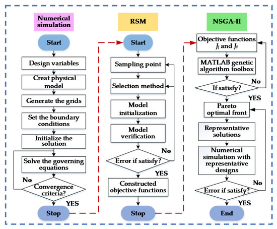
Figure 5.
The flow chart of the optimization process.
3.2. Design Variables and Objective Functions
In the study of the structural optimization of vortex generators, it is well established from prior research that parameters such as dimensionless height, attack angle, pitch ratio, and orientation significantly influence flow and heat transfer performance. This paper designs a biomimetic vortex generator with distinct variable curvatures and orientations. It consists of two curvatures, which are denoted as δ1 and δ2. The objective function is defined by the friction factor of the channel, as well as the Colburn factor related to the reaction heat transfer. A multi-objective optimization mathematical model, based on design variables and their constraints, is established as follows:
where the constants m = −100 and n = 10 are defined to adjust the size of the objective function. Since the value of m is negative, the smaller the value of Jj, the better the heat transfer performance. The constraints of the design variables under different orientations are as follows:
3.3. Response Surface Method
The response surface method (RSM) is employed to model the functional relationship between design variables and response values using multiple quadratic regression equations. During the numerical solution process, the distribution of the Corburn factor (j) and the friction factor (f) were calculated using Equation (19). Subsequently, the objective functions Jj and Jf were formulated utilizing the response surface method. The accuracy of the fitting equations is evaluated through the root mean square error (RMSE) and the Multivariate Statistical Coefficient (R2), as presented in Equations (21) and (22) [33]. Notably, the closer the RMSE is to 0 and the R2 is to 1, the more precise the fitting equation.
4. Results and Discussions
4.1. Effect of Structural Parameters on Drag Reduction Performance
Figure 6 illustrates the impact of key design parameters (δ1, δ2) within a certain range (−0.05 ≤ δ1 ≤ 0.15, −0.2 ≤ δ2 ≤ 0 for (a); −0.05 ≤ δ1 ≤ 0.15, 0 ≤ δ2 ≤ 0.2 for (b)), which define the structure of the SCVGs, on the flow channel friction factor and the comprehensive evaluation metric of the heat exchanger. Among these, δ1 = 0 and δ2 = 0 represent the initial design configuration. Specifically, Figure 6(a1,b1) depict the variation of the friction factor (f) with respect to the design variables across different orientations. The findings indicate the existence of a minimum friction factor, with fmin exhibiting minimal variation across different orientations. Notably, the D-type orientation achieves a slightly lower fmin, with optimal curvature parameters identified as δ1 = 0.05 and δ2 = −0.15, classifying the SCVGs as a D2 configuration. In contrast, for the U-type orientation, the optimal curvature parameters are δ1 = 0.05 and δ2 = 0.15, corresponding to the U1 configuration of the SCVGs. From the perspective of the comprehensive evaluation metric (JF), the flow channel exhibits an initial increase followed by a decrease with variations in δ1 and δ2 across different orientations, existing as a maximum value for JF. It is important to note that the optimal values of the design variables identified in this analysis are not the actual values. Therefore, further optimization is necessary to determine the actual optimal design variables and the maximum comprehensive evaluation metric JFmax.
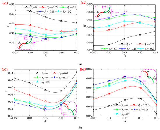
Figure 6.
The influence of curvature on the f and JF under different orientations: (a) D-type, (a1,a2) f; (b) U-type, (b1,b2) JF.
In the context of the SCVGs exhibiting the minimum friction factor and maximum comprehensive evaluation metric as depicted in Figure 6, this study examines the impact of convective heat transfer performance across varying Reynolds numbers and attack angles. Analysis of Figure 7(a1,b1) reveals that, within the current research parameters (30° ≤ β ≤ 50°, 600 ≤ Re ≤ 2200), an increase in the attack angle results in a general upward trend in the friction factor. Notably, the minimum friction factor is observed at β = 30°. Conversely, as the Reynolds number rises, the friction factor in the flow channel diminishes, and the effect of the Reynolds number on the friction factor becomes more significant with a higher β. Figure 7(a2,b2) further illustrate that an increase in the attack angle leads to a general decline in the comprehensive evaluation metric (JF) of the flow channel. The peak comprehensive evaluation metric is also observed at β = 30°. However, with rising Reynolds numbers, the comprehensive evaluation metric of the flow channel consistently diminishes. The highest comprehensive evaluation metric is achieved at Re = 600. Based on the preceding analysis, it is evident that, from the standpoint of the comprehensive evaluation metric within the scope of the design variables examined in this study, the optimal design parameters are identified as β = 30° and Re = 600. This paper mainly examines how the new SCVG structure affects flow and heat transfer performance. Consequently, in subsequent research, the attack angle is fixed at 30°, and the Reynolds number is set at 600 as a constant design variable.
Figure 7.
Thermo-hydraulic characteristics for varying structural parameters: (a) D-type, (a1,a2) f; (b) U-type, (b1,b2) JF.
4.2. Response Surface Analysis
Using the SCVGs in the U-type orientation as an example, Figure 8 presents the scatter plot of the objective function against the design variables δ1 and δ2, along with the response surface derived through RSM. The figure illustrates that the majority of the scatter points align with the curved surface, although a few points are located outside the surface. Notably, the multivariate statistical coefficients (R2) for these points exceed 0.9, and the root mean square error (RMSE) is less than 1 × 10⁻².
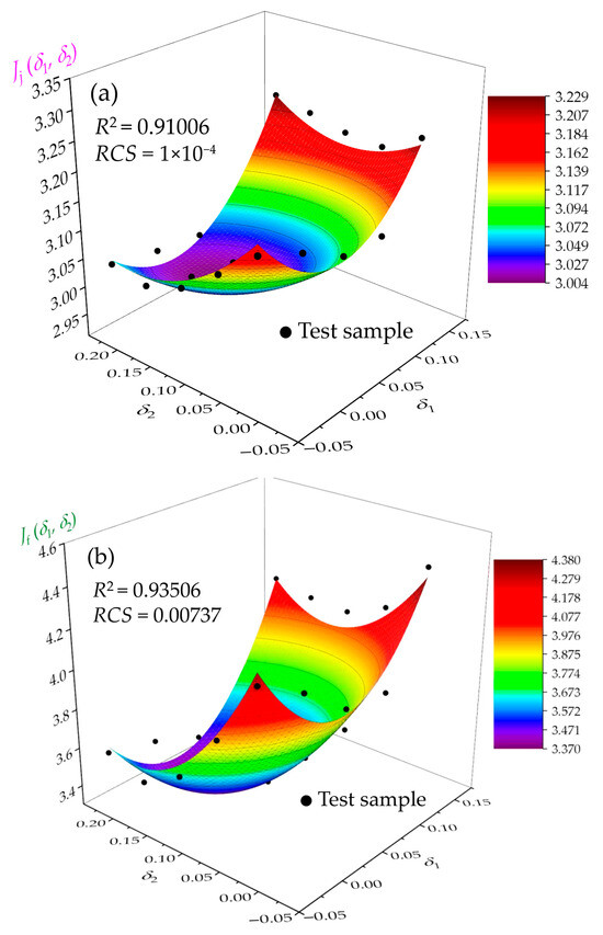
Figure 8.
Response surface of the objective function changing with design variables: (a) Jj vs. δ; (b) Jf vs. δ.
The RSA models that have been constructed, employing a polynomial formulation for both Jj and Jf, can be mathematically represented as follows:
Figure 9 presents the Pareto solution set for SCVGs under the U-type orientation. It is apparent that the objective functions Jj and Jf generally exhibit a monotonically decreasing relationship. Specifically, the heat transfer performance Jj of the channel diminishes as the friction factor Jf increases. The original point corresponds to the initial design (δ1 = 0, δ2 = 0) of SCVGs prior to optimization. At point A, the heat transfer performance of the channel is maximized, while at point B, the friction factor is minimized. Point I1 represents the ideal point, which theoretically achieves both the maximum Jj and the minimum Jf, although it is unattainable in practice. Conversely, point I2 is a non-ideal point, opposite to I1. To further validate these observations, several representative points were selected to evaluate the discrepancies between the Pareto optimal values and the numerical results. As shown in Table 2, the maximum errors between the theoretical and simulated values for the objective functions Jj and Jf are 0.61% and 2.31%, respectively, indicating a strong agreement. Then, the following analysis is based on the results of the numerical solution.
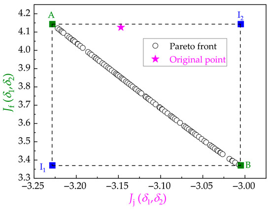
Figure 9.
Pareto-optimal front with the objective functions.
Table 2.
Comparison of Pareto front and numerical data.
The preceding analysis suggests that the enhancement of Jj is concurrently accompanied by an increase in Jf. Figure 10 presents a comprehensive evaluation metric JF comparison of the five representative points listed in Table 2 with the initial design (δ1 = 0, δ2 = 0) of SCVGs prior to optimization. As illustrated in Figure 10, the JF of the channels associated with the five representative points surpasses that of the initial design. This indicates that the optimized SCVGs exhibit a superior heat exchange effect compared to their pre-optimization state. Notably, the channel structure at representative point 1 (δ1 = 0.0662, δ2 = 0.1626) achieves the highest comprehensive evaluation metric, and it is named U1-Opt. Ultimately, the optimal curvatures for the D-type orientation, determined using the aforementioned method, are δ1 = 0.0788 and δ2 = −0.1290, and it is named D2-Opt.
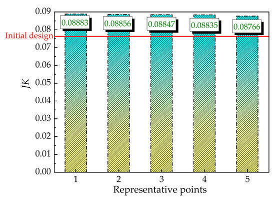
Figure 10.
Comparison of the comprehensive evaluation metric.
4.3. Analysis of Flow and Heat Transfer Performance of the Optimized Structure
The thermohydraulic performance of the air-side flow channel in a compact heat exchanger equipped with a vortex generator is significantly influenced by the distribution of temperature, velocity, and pressure within the flow channel. Figure 11 illustrates the temperature distribution at the z = 2.5 mm cross-section (z = 0.5 h) in the optimized SCVG channel under various orientations.
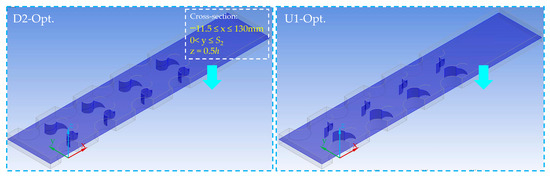
Figure 11.
z = 2.5 mm section position.
Figure 12 reveals that, for the D-type orientation, the temperature surrounding the heating tube in the front row is relatively low, whereas the extent of the high-temperature zone around the heating tube in the back row progressively increases. As the fluid flows, it undergoes continuous heating. In contrast, for the U-type orientation, the high-temperature regions around the heating tube are relatively uniform along the flow direction and exhibit an approximately periodic distribution. Consequently, the D-type orientation demonstrates a superior heat exchange effect. Additionally, in the FVG channel, the high-temperature zone is more extensive compared to that in the SCVG channel. The temperature distribution within the flow channel serves as an indicator of the efficacy of the heat transfer process. Consequently, when examining flow channels with varying configurations, it is evident that the heat transfer performance of the FVG channel consistently surpasses that of the SCVG flow channel, which demonstrates comparatively weaker performance.
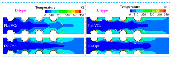
Figure 12.
Temperature distribution of different VG channels.
Figure 13 illustrates the velocity distribution at a cross section where z = 2.5 mm. The heat transfer performance of the fin-and-tube heat exchanger is predominantly influenced by the flow velocity in proximity to the tube wall. In the D-type orientation, a significant high-velocity region is established around the tubes and between the VGs. Notably, there is an absence of flow dead zones with zero velocity between the adjacent tubes, resulting in enhanced heat exchange efficacy. This is evidenced in the temperature contour by an expanded high-temperature zone. Conversely, in the U-type orientation, distinct regions of reduced velocity are observed around the tubes, thereby diminishing the heat transfer performance. Nevertheless, the area exhibiting zero flow velocity behind the VGs is reduced, indicating a lower friction factor of the vortex generator to the fluid. Additionally, for the optimized SCVG structure with varying orientations, the flow velocities are consistently lower than those in the FVG channels. This suggests that the disturbance effect of the SCVG on the fluid is relatively minimal, leading to a slight reduction in heat transfer performance.
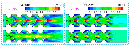
Figure 13.
Velocity distribution of different VG channels.
Figure 14 illustrates the pressure distribution across the same cross section. The figure demonstrates a consistent decrease in pressure along the flow direction, with the pressure differential indicating the magnitude of channel friction factor. Notably, the pressure difference between the inlet and outlet of the FVG channel is substantial. Specifically, the pressure differential in the flow channel with a U-type orientation is smaller compared to that with a D-type orientation. This suggests that the vortex generator exerts a relatively minor disturbance on the fluid, as evidenced by the velocity contour: the area of the flow dead zone behind the VGs is reduced under the U-type orientation. Additionally, in the optimized SCVG flow channel, the pressure difference between the inlet and outlet is relatively minimal, and the pressure distribution remains consistent across different orientations. This indicates that the optimized SCVGs (D2-Opt. and U1-Opt.) can achieve similar flow effects regardless of the orientation.
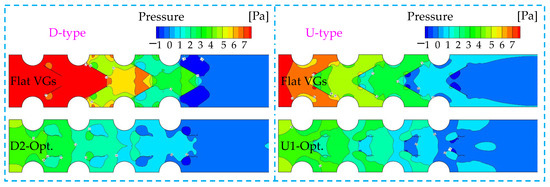
Figure 14.
Pressure distribution of different VG channels.
Figure 15 depicts the cross section at the tail of the first row of VGs (x = 14 mm). The vortex structures generated by various orientations of VGs are illustrated in Figure 16. Given the symmetry of the model, a representative half of the cross section was selected for analysis. The velocity vector and vorticity (Ω) distribution at this cross section indicate that the area of high vorticity in the D-type orientation is relatively extensive, primarily localized near the VGs. This observation aligns with the presence of a significant flow dead zone observed at the rear of the VGs, as evidenced by the velocity distribution presented in Figure 13. Conversely, the flow velocity on both sides distant from the VGs is relatively high, resulting in reduced vorticity that approaches zero. In the case of the U-type orientation, the vortex distribution appears more uniform, suggesting the presence of multiple vortex structures at the rear of the VGs. This conclusion is further supported by the velocity distribution. Notably, from the perspective of the velocity vector diagram, the optimized SCVG channel facilitates the generation of multiple longitudinal vortex structures. The formation of these longitudinal vortices enhances the alignment between the velocity vector and the temperature gradient, thereby improving heat transfer performance.
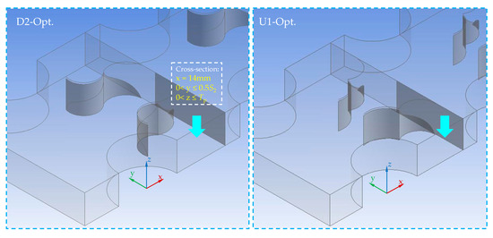
Figure 15.
x = 14 mm section position.
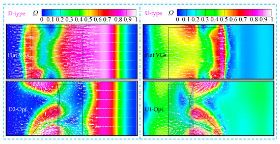
Figure 16.
Vortex structure distribution at the tail section of VGs.
4.4. Comparisons with Other Drag-Reduction VGs
Different drag-reducing VGs are arranged in the D-type orientation, as shown in the Figure 17. Figure 18 provides a comparative analysis between the optimized SCVGs developed in this study and other drag-reducing VGs, specifically the curved and perforated VGs. It is important to highlight that the parameter dimensions (e.g., l = 10 mm, h = 0.5 l, etc.) and layout method (β = 30°) of these drag-reducing VGs are consistent with those investigated in this study, with the exception of their structural shape. Notably, the bending depth of the curved VGs (CVGs) is d = 1.5 mm, and the diameter of the perforations in the VGs is r = 2 mm, with varying numbers of uniformly arranged holes.
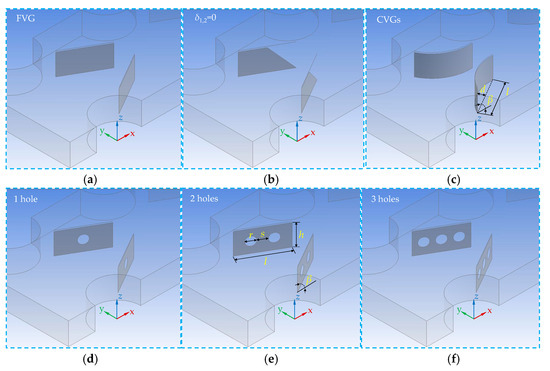
Figure 17.
Drag-reducing VGs in D-type orientation: (a) FVGs; (b) δ1,2 = 0; (c) CVGs; (d) 1 hole; (e) 2 hole; (f) 3 hole.
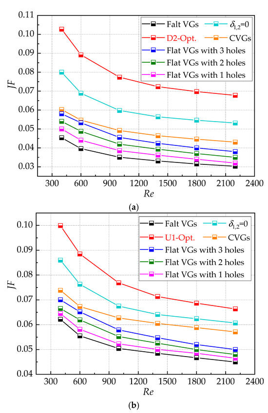
Figure 18.
Comparisons of JF in optimized SCVGs with the values in other structures: (a) D-type; (b) U-type.
From the perspective of the comprehensive evaluation metric JF, the optimized SCVG channel exhibits a significant enhancement over other VG flow channels. For example, in the D-type orientation, within the Reynolds number range of 400 to 2200, there is an increase of 123.7% to 126.5% compared to the FVG channel, which demonstrates the lowest JF. In comparison to the initial design of the SCVGs (where curvature δ1,2 = 0), the optimized flow channel JF exhibits an enhancement ranging from 27.44% to 28.41%. This indicates that the curvature parameter significantly influences the flow and heat transfer performance of the channel, demonstrating that the optimization process has yielded a substantial improvement. In comparison to the CVG flow channel, the JF shows an enhancement of 57.4% to 70.5%. It is observed that the comprehensive evaluation metric improves with an increase in the number of holes in the VGs. Specifically, when compared to VGs with three holes, the JF increases by 77.1% to 78.3%. A prior study investigated perforated VGs and optimized the attack angle, achieving an optimal JF of approximately 0.068 (for an FVG with one hole, an attack angle of 10°, and Re = 400) [8]. Under the same Reynolds number, the SCVG channel developed in this study can enhance the JF by more than 50%.
5. Conclusions
To improve the heat transfer efficiency of air-side flow channels in compact heat exchangers, a novel SCVG has been proposed. An analysis of the interactions among various design parameters revealed that curvature (δ1, δ2) significantly influences the flow and heat transfer performance of the flow channels. The response surface methodology, coupled with a multi-objective genetic algorithm, was employed to optimize and determine the optimal curvatures. The principal findings of this research are as follows:
(1) According to the flow and heat transfer contour diagram, the SCVG designed in this study substantially reduces the flow friction factor, although there is a slight decrease in heat transfer performance. Notably, the key parameters of the biomimetic design, specifically the curvatures δ1 and δ2, exert a significant influence on flow and heat transfer performance. The optimized SCVG (δ1 = 0.0788, δ2 = −0.1290, D-type) demonstrates an improvement in overall performance ranging from 27.44% to 28.41% compared to the initial design (δ1 = δ2 = 0, D-type). The optimal configuration for the D-type orientation is identified as D2-Opt., while for the U-type orientation, it is U1-Opt. (δ1 = 0.0662, δ2 = 0.1626, U-type).
(2) The enhanced heat transfer mechanism of the SCVGs is characterized by the formation of multiple longitudinal vortex structures downstream, which enhances the field synergy effect. Furthermore, various orientations can produce similar secondary flow structures and obtain optimal configurations, resulting in a similar comprehensive evaluation metric JF for the flow channel.
(3) In comparison to the FVG channel, which exhibits the lowest comprehensive evaluation metric, the JF of the SCVG channel has increased by over 120%. Additionally, when compared to other existing efficient and low-friction factor vortex generator structures, the comprehensive evaluation metric of the optimized SCVG structure has improved by more than 50%.
(4) Future research will concentrate on investigating the potential application domains of the SCVGs optimized in this study, with particular emphasis on their drag reduction effects in the flow channels of various heat exchangers, such as staggered finned tube heat exchangers. Furthermore, the comprehensive performance of the SCVGs will be further assessed through experimental research.
Author Contributions
Z.W.: Software, writing—original draft preparation, visualization, validation, formal analysis, and investigation; X.Y.: Conceptualization, methodology, and writing—review and editing; X.G.: Resources and supervision; Y.L.: Data curation and project administration. All authors have read and agreed to the published version of the manuscript.
Funding
This research was funded by the Natural Science Foundation of Guangxi Province, grant number 2025GXNSFAA069202; Research Foundation Ability Enhancement Project for Young and Middle-aged Teachers in Guangxi Universities, grant number 2025KY0841.
Data Availability Statement
All data to support the results of this study are included in this article.
Conflicts of Interest
The authors affirm the absence of any competing interests.
Nomenclature
| A | symmetric tensor |
| B | antisymmetric tensor |
| c | midpoint |
| Cp | constant-pressure specific heat, J/(kg·K) |
| d | bending length, mm |
| DH | hydraulic diameter, mm |
| D | tube diameter, mm |
| f | friction factor |
| h | height of VGs, mm; convective heat-transfer coefficient, W/(m2·K) |
| j | Colburn factor |
| J | objective function |
| JF | comprehensive evaluation metric |
| k | turbulent kinetic energy, m2/s2 |
| l | chord length of VGs |
| m, n | constants |
| N | rows of tubes |
| Nu | Nusselt number |
| p | Pressure, Pa |
| Pr | Prandtl number |
| q | heat flux, W/m2 |
| Re | Reynolds number |
| S1, 2 | spacings between adjacent tubes, mm |
| T | temperature, K |
| Tp | spacing between adjacent fins, mm |
| Δtm | logarithmic average temperature difference, K |
| u, v, w | velocity component, m/s |
| Subscript | |
| down | bottom surface of channel |
| i | number of variables |
| in | channel inlet |
| min | minimum |
| max | maximum |
| opt | optimal value |
| out | channel outlet |
| up | top surface of channel |
| w | wall surface |
| Greek letters | |
| β | attack angle |
| δ | curvature |
| ε | turbulent dissipation rate, m2/s3 |
| λ | heat conductivity coefficient, W/(m·K) |
| μ | fluid viscosity, Pa·s |
| ρ | fluid density, kg/m3 |
| Ω | vorticity |
| Abbreviations | |
| CFD | Common-Flow-Down |
| CFU | Common-Flow-Up |
| SCVG | Seagull-Inspired Curved Vortex Generator |
| FVG | Flat VGs |
| VG | Vortex Generator |
| NSGA-II | Non-Dominated Sorting Genetic Algorithm II |
| RSM | Response Surface Method |
| RMSE | Root Mean Square Error |
| R2 | Multivariate Statistical Coefficient |
References
- Tao, W.Q. Numerical Heat Transfer; Xi’an Jiaotong University Press: Xi’an, China, 2001. [Google Scholar]
- Luo, Y.; Li, G.; Bennett, N.S.; Luo, Z.; Munir, A.; Islam, M.S. Heat transfer enhancement in heat exchangers by longitudinal vortex generators: A review of numerical and experimental approaches. Energies 2025, 18, 2896. [Google Scholar] [CrossRef]
- Xu, L.; Li, J.; Sun, K.; Xi, L.; Gao, J.; Li, Y. Heat analysis and optimal design of fin-and-tube heat exchanger with X-truss vortex generators. Int. Commun. Heat. Mass. 2024, 152, 107248. [Google Scholar] [CrossRef]
- Demirag, H.Z.; Dogan, M.; Igci, A.A. The numerical analysis of novel type conic vortex generator and comparison with known VGs for heat transfer enhancement. Heat. Mass. Transfer. 2022, 58, 735–762. [Google Scholar] [CrossRef]
- Naik, H.; Tiwari, S.; Kim, H.D. Flow and thermal characteristics produced by a curved rectangular winglet vortex generator in a channel. Int. Commun. Heat. Mass. 2022, 135, 106103. [Google Scholar] [CrossRef]
- Zhang, L.; Yan, X.; Zhang, Y.; Feng, Y.; Li, Y.; Meng, H.; Zhang, J.; Wu, J. Heat transfer enhancement by streamlined winglet pair vortex generators for helical channel with rectangular cross section. Chem. Eng. Process. 2020, 147, 107788. [Google Scholar] [CrossRef]
- Promvonge, P.; Skullong, S. Thermal-hydraulic performance enhancement of solar receiver channel by flapped V-baffles. Chem. Eng. Res. Des. 2022, 182, 87–97. [Google Scholar] [CrossRef]
- Modi, A.J.; Kalel, N.A.; Rathod, M.K. Thermal performance augmentation of fin-and-tube heat exchanger using rectangular winglet vortex generators having circular punched holes. Int. J. Heat. Mass. Transf. 2020, 158, 119724. [Google Scholar] [CrossRef]
- Saini, P.; Dhar, A.; Powar, S. Performance enhancement of fin and tube heat exchanger employing curved trapezoidal winglet vortex generator with circular punched holes. Int. J. Heat. Mass. Transf. 2023, 209, 124142. [Google Scholar] [CrossRef]
- Pérez, R.B.; Pérez, A.M.; Suárez, D.S. Influence of the punched holes on thermohydraulic performance and flow pattern of rectangular channels with a pair of perforated vortex generators. Int. J. Heat. Mass. Transf. 2022, 184, 122291. [Google Scholar] [CrossRef]
- Promvonge, P.; Promthaisong, P.; Skullong, S. Numerical heat transfer in a solar air heater duct with punched delta-winglet vortex generators. Case Stud. Therm. Eng. 2021, 26, 101088. [Google Scholar] [CrossRef]
- Pérez, A.M.; Altamirano, C.F.-A.; Pérez, R.B. Parametric analysis of the influence of geometric variables of vortex generators on compact louver fin heat exchangers. Therm. Sci. Eng. Prog. 2022, 27, 101151. [Google Scholar] [CrossRef]
- Oh, Y.; Kim, K. Effects of position and geometry of curved vortex generators on fin-tube heat-exchanger performance characteristics. Appl. Therm. Eng. 2021, 189, 116736. [Google Scholar] [CrossRef]
- Ramanathan, S.; Thansekhar, M.R.; Kanna, P.R.; Gunnasegaran, P. A new method of acquiring perquisites of recirculation and vortex flow in sudden expansion solar water collector using vortex generator to augment heat transfer. Int. J. Therm. Sci. 2020, 153, 106346. [Google Scholar] [CrossRef]
- Liu, L.; Ni, Z.; Tang, H.; Xu, H.; Jiang, B. Heat transfer performance and flow characteristics of a heat exchange tube with isosceles trapezoidal winglet longitudinal vortex generators. Energies. 2025, 18, 1717. [Google Scholar] [CrossRef]
- Rhakasywi, D.; Wasito, A.; Wijaya, E.P.; Rizal, R.; Adanta, D. Effect of vortex generator angle on fin and tube heat exchanger. J. Adv. Res. Numer. Heat. Transf. 2024, 16, 82–99. [Google Scholar] [CrossRef]
- Wang, Y.; Zhao, W.; Wang, P.; Jiang, J.; Luo, X. Thermal Performance of Elliptical Fin-and-Tube Heat Exchangers with Vortex Generator under Various Inclination Angles. J. Therm. Sci. 2021, 30, 257–270. [Google Scholar] [CrossRef]
- Sharma, V.R.; Sai, S.S.; Madhwesh, N.; Manjunath, M.S. Enhanced thermal performance of tubular heat exchanger using triangular wing vortex generator. Cogent Eng. 2022, 9, 2050021. [Google Scholar] [CrossRef]
- Wang, J.; Zeng, L.; He, Y. Thermal performance augmentation of microchannel using curved rectangular winglet vortex generators having rectangular perforation. Chem. Eng. Sci. 2025, 302, 120860. [Google Scholar] [CrossRef]
- İĞCİ, A.A. Enhancing heat transfer with a hybrid vortex generator combining delta wing and winglet designs: A numerical study using the GEKO turbulence model. Appl. Therm. Eng. 2025, 258, 124604. [Google Scholar] [CrossRef]
- Sharfabadi, M.M.; Mobadersani, P.; Nourpour, L. A Numerical study on heat transfer in the channel with delta winglet pair vortex generators. Int. J. Heat. Technol. 2022, 39, 1305–1312. [Google Scholar] [CrossRef]
- Shi, W.N.; Liu, T.F.; Song, K.W.; Zhang, Q.; Hu, W.L.; Wang, L.B. The optimal longitudinal location of curved winglets for better thermal performance of a finned-tube heat exchanger. Int. J. Therm. Sci. 2021, 167, 107035. [Google Scholar] [CrossRef]
- Wang, Y.; Wang, J.; Zhang, W.; Zhao, Z. Performance optimization of plate-fin heat exchanger with curved vortex generators based on response surface method. Int. J. Therm. Sci. 2025, 210, 109659. [Google Scholar] [CrossRef]
- Dogan, M.; Erzincan, S. Experimental investigation of thermal performance of novel type vortex generator in rectangular channel. Int. Commun. Heat. Mass. 2023, 144, 106785. [Google Scholar] [CrossRef]
- Yang, W.; Zhou, F.; Chen, X.; Zhang, Y. Performance analysis of axial air-cooling system with shark-skin bionic structure containing phase change material. Energy Convers. Manag. 2021, 250, 114921. [Google Scholar] [CrossRef]
- Wang, D.; Liu, H. A novel aerodynamic drag-reduction mechanism using dolphin-inspired ultrasonic microvibrations. Sci. Rep. 2025, 15, 13691. [Google Scholar] [CrossRef]
- Wang, Z.; Li, B.; Luo, Q.; Zhao, W. Effect of wall roughness by the bionic structure of dragonfly wing on microfluid flow and heat transfer characteristics. Int. J. Heat. Mass. Transf. 2021, 173, 121–201. [Google Scholar] [CrossRef]
- Lyu, Y.; Yu, H.; Hu, Y.; Shu, Q.; Wang, J. Bionic design for the heat sink inspired by phyllotactic pattern. Proc. Inst. Mech. Eng. C J. Mech. Eng. Sci. 2020, 235, 3087–3094. [Google Scholar] [CrossRef]
- Li, X.J.; Zhang, J.Z.; Tan, X.M.; Zhang, Q.C.; Lu, E.H. Investigation of fluid flow and heat transfer in a narrow channel with micro barchan-dune-shaped humps. Int. J. Mech. Sci. 2022, 231, 107589. [Google Scholar] [CrossRef]
- Niu, Z.; Hao, M.; Wang, Y.; Zhang, J. Numerical simulation of enhanced heat transfer in new type of bird beak vortex generator. Acta. Energ. Sol. Sin. 2024, 45, 264–271. [Google Scholar] [CrossRef]
- Gonül, A.; Okbaz, A.; Kayaci, N.; Dalkilic, A.S. Flow optimization in a microchannel with vortex generators using genetic algorithm. Appl. Therm. Eng. 2022, 201, 117738. [Google Scholar] [CrossRef]
- Hu, D.L.; Zhang, Q.; Song, K.W.; Gao, C.; Zhang, K.; Su, M.; Wang, L.B. Performance optimization of a wavy finned-tube heat exchanger with staggered curved vortex generators. Int. J. Therm. Sci. 2023, 183, 108489. [Google Scholar] [CrossRef]
- Li, Z.; Feng, Z.; Zhang, Q.; Zhou, J.; Zhang, J.; Guo, F. Thermal-hydraulic performance and multi-objective optimization using ANN and GA in microchannels with double delta-winglet vortex generators. Int. J. Therm. Sci. 2023, 193, 108489. [Google Scholar] [CrossRef]
- Sharma, R.; Mishra, D.P.; Wasilewski, M.; Brar, L.S. Application of response surface methodology and artificial neural network to optimize the curved trapezoidal winglet geometry for enhancing the performance of a fin-and-tube heat exchanger. Energies 2023, 16, 4209. [Google Scholar] [CrossRef]
- Xie, C.; Yan, G.; Ma, Q.; Elmasry, Y.; Singh, P.K.; Algelany, A.M.; Makatar, W. Flow and heat transfer optimization of a fin-tube heat exchanger with vortex generators using Response Surface Methodology and Artificial Neural Network. Case Stud. Therm. Eng. 2022, 39, 102445. [Google Scholar] [CrossRef]
- Liang, X.; Kumar, N.B.; Mansir, I.B.; Singh, P.K.; Abed, A.M.; Dahari, M.; Nasr, S.; Albalawi, H.; Cherif, A.; Makatar, W. Management of heat transfer and hydraulic characteristics of a micro-channel heat sink with various arrangements of rectangular vortex generators utilizing artificial neural network and response surface methodology. Case Stud. Therm. Eng. 2023, 44, 102850. [Google Scholar] [CrossRef]
- Feng, Y.; Xu, R.; Cao, Y.; Wu, X.; Liang, C.; Zhang, L. Optimization of H-type finned tube heat exchangers with combinations of longitudinal vortex generator, dimples/protrusions and grooves by Taguchi method. Int. Commun. Heat. Mass. 2023, 143, 106709. [Google Scholar] [CrossRef]
- Liu, A.; Wang, G.; Wang, D.; Peng, X.; Yuan, H. Study on the thermal and hydraulic performance of fin-and-tube heat exchanger based on topology optimization. Appl. Therm. Eng. 2021, 197, 117738. [Google Scholar] [CrossRef]
- Yang, X.; Hu, J.; Fan, Y.; Min, C.; Wang, K. Enhanced heat dissipation of ribbed channels based on the coupling optimization of multiple structural parameters. Appl. Therm. Eng. 2023, 235, 121362. [Google Scholar] [CrossRef]
Disclaimer/Publisher’s Note: The statements, opinions and data contained in all publications are solely those of the individual author(s) and contributor(s) and not of MDPI and/or the editor(s). MDPI and/or the editor(s) disclaim responsibility for any injury to people or property resulting from any ideas, methods, instructions or products referred to in the content. |
© 2025 by the authors. Licensee MDPI, Basel, Switzerland. This article is an open access article distributed under the terms and conditions of the Creative Commons Attribution (CC BY) license (https://creativecommons.org/licenses/by/4.0/).