Article

Wireless Temperature Monitoring of a Shaft Based on Piezoelectric Energy Harvesting

Faculty of Mechanical Engineering and Robotics, AGH University of Krakow, al. A. Mickiewicza 30, 30-059 Krakow, Poland
*
Author to whom correspondence should be addressed.
Energies 2025, 18(14), 3620; https://doi.org/10.3390/en18143620
Submission received: 18 June 2025 / Revised: 4 July 2025 / Accepted: 5 July 2025 / Published: 9 July 2025
(This article belongs to the Special Issue Innovations and Applications in Piezoelectric Energy Harvesting)

Abstract

Wireless structural health monitoring is needed for machine elements of which the working motions prevent wired monitoring. Rotating machine shafts are such elements. Wired monitoring of the rotating shaft requires making significant changes to the shaft structure, primarily drilling a hole in the longitudinal axis of the shaft and installing a slip ring assembly at the end of the shaft. Such changes to the shaft structure are not always possible. This paper proposes the use of piezoelectric energy harvesting from a rotating shaft to power wireless temperature monitoring of the shaft surface. The main components of presented wireless temperature monitoring are three piezoelectric composite patches, three thermal fuses, a system for storing and distributing the harvested energy, and a radio transmitter. This article contains the results of experimental research of such wireless monitoring on a dedicated laboratory stand. This research included four connections of piezoelectric composite patches: delta, star, parallel, and series for different capacities of a storage capacitor. Based on experimental results, three parameters that influence the frequency of sending data packets by the presented wireless temperature monitoring are identified: amplitude of stress in the rotating shaft, rotation speed of the shaft, and the capacity of a storage capacitor.

1. Introduction

Piezoelectric materials are, among other purposes, used in devices that are used for wireless structural health monitoring of structures [1]. The structures that are monitored in this way are usually difficult to access and/or located far from energy sources, e.g., elements of bridges, buildings, masts, etc. [2]. However, the need for wireless monitoring of the condition of structures occurs not only in facilities that are difficult to access and/or located far from energy sources. Wireless monitoring of the condition of structures is also needed for machine elements of which the working motions prevent their wired monitoring [3]. Rotating machine shafts are such elements.
Shaft temperature may increase due to shaft misalignment, which firstly causes an increase in temperature, among other things, in the bearings or/and clutches and then the shaft [4,5]. The increase of shaft temperature may also be caused by damaged bearings, excessive friction of machine elements, cracks, or exceeding the permissible shaft stresses. Therefore, an increase in shaft temperature above the permissible level indicates a system failure, and this condition should be monitored [6]. In the literature, structural health monitoring methods are proposed, in which the temperature measurement of rotating machinery is a supplement to the standard vibration monitoring of these machines [6]. It is usually not necessary to monitor the current temperature value, and information about exceeding the alarm threshold is sufficient. Contact monitoring of the temperature of the rotating shaft requires the use of a slip ring assembly [7]. The use of a slip ring assembly requires available space on the shaft end for its installation and an inner canal drilled in the longitudinal axis of the shaft for routing cables between the temperature sensor and the slip ring assembly [8]. Non-contact techniques for measuring the temperature of a rotating shaft are being developed, but they also have their limitations, e.g., the use of a radiation thermometer is limited in the case of metal shafts due to the influence of light energy reflected from the shiny metal surface [9]. Considering that the slip ring assembly cannot be used in every shaft, temperature monitoring is most often performed by measuring the bearings’ temperature. Temperature monitoring of bearings also creates difficulties, e.g., measuring only the outer bearing housing allows the temperature increase inside the bearing to be detected only after some time [10]. Non-contact bearing temperature monitoring, e.g., infrared thermometers with wireless signal transmission are being developed, but these encounter other problems, e.g., electromagnetic interference and negative impact of harsh bearing environmental conditions on wireless signal transmission [11].
The main problem in contact measurement of the temperature of a rotating shaft is the power supply of the temperature sensor, which requires the lead of cables to the temperature sensor. The lead of cables requires making significant changes to the shaft structure, primarily drilling a hole in the longitudinal axis of the shaft and installing a slip ring assembly at the end of the shaft. Such changes to the shaft structure are not always possible. Piezoelectric materials, glued on the surface of the rotating shaft, can be a source of electric energy to power the temperature sensor. Piezoelectric materials are most often used to harvest energy from vibrations of engineering structure elements, e.g., bridges [12], trusses [13], etc. Typically, the main element of the harvesters used then is a cantilever beam, which contains a piezoelectric material in its structure [14]. The use of piezoelectric materials for energy harvesting from rotating machine elements is reported much less frequently in the literature. Typically, this type of energy harvesting requires adding a special structure to the rotating element of the machine, which is most often also based on a cantilever beam [15]. Mounting energy harvesters with protruding beam elements to the surface of a rotating shaft is usually not possible due to safety reasons or lack of free space. In [16], electric energy is harvested by the piezoelectric composites glued directly onto the shaft surface.
A separate problem is the transmission of measurement data from the sensor to the monitoring system control unit. Radio transmission can be used to transmit measurement data acquired by the sensor [17]. Hence, the harvested electrical energy must be appropriately distributed to both power the temperature sensor and to power the radio transmitter of the wireless measurement data transmission system [18,19]. Powering all the elements of such a wireless temperature sensor requires a relatively large amount of energy, up to several dozen mW [20]. Continuous supply of such an amount of energy to a wireless sensor by piezoelectric energy harvesting is practically impossible because piezoelectric harvesters usually generate less energy, which is confirmed by the results presented by various researchers [21]. Therefore, research is underway on wireless sensors that can operate efficiently when periodically supplied with stored energy obtained by piezoelectric energy harvesting. Periodic power supply reduces the measurement sensitivity of the wireless sensor because it can only periodically transmit the acquired measurement data. This paper proposes a wireless temperature monitoring system that retains sensitivity despite being supplied with periodically harvested energy. The paper presents a prototype of a wireless monitoring system of temperature based on connecting the thermal fuses directly to a radio transmitter and an application of periodically powering this radio transmitter with harvested energy stored in a storage capacitor, and it analyzes the factors that influence the sensitivity of wireless shaft temperature measurement.

2. Materials and Methods

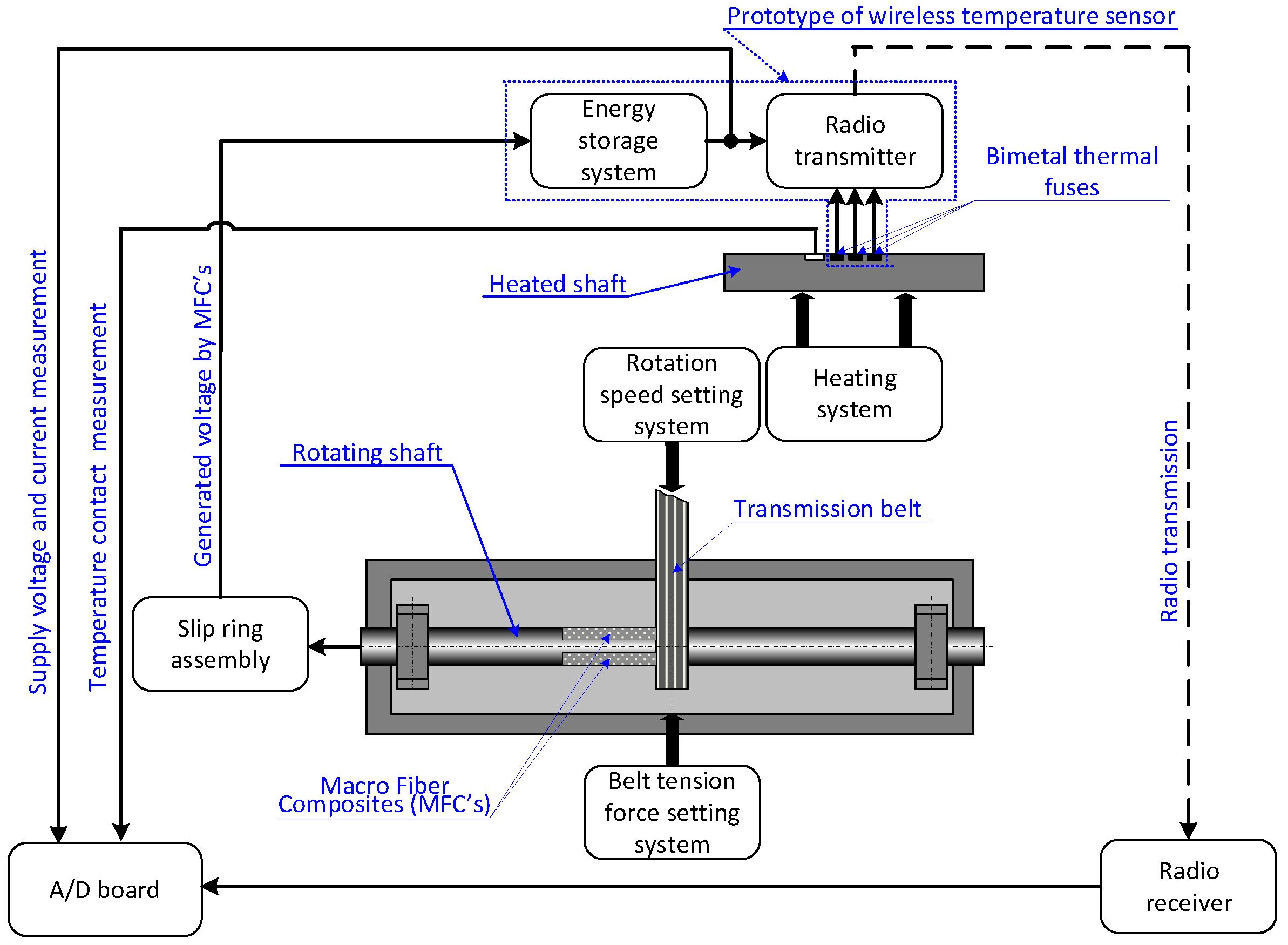
2.1. Laboratory Setup

Laboratory experiments were carried out on a laboratory stand consisting of four main parts: a rotating steel shaft equipped by a belt transmission and a belt tension force setting system, a heated steel shaft equipped by a heating system, a prototype of wireless temperature sensor, and a measuring system equipped by a slip ring assembly and A/D board. The diagram of the laboratory stand is shown in Figure 1.
The view of the laboratory stand is shown in Figure 2. The rotating shaft (10) was driven by the belt transmission (11), and the belt tension was changed by the screw mechanism (12). The stationary shaft (8) was heated by a transformer system (9). The prototype of wireless temperature monitoring consisted of three patches of macro fiber composite (8) glued on the rotating shaft surface, a rectifier system (1), an energy storage and distribution system (3), a radio transmitter (4), and bimetal thermal fuses (5). A slip ring assembly (7) was used to transmit the electrical energy, generated by the MFCs, to the energy storage system.
The rotating shaft was made from steel and had an annulus cross-section. The external diameter (dso) was 40 mm, and the internal diameter (dsi) was 36 mm. The rotating shaft was supported on two bearings, and its length was 620 mm. The rotation speed (f) setting system made it possible to obtain a shaft rotation speed of up to 20 rps. The rotation speed was set once at the beginning of each experiment. The setting system of belt tension force (Fbt) made it possible to obtain a shaft loading force of up to 500 N. The force was set once at the beginning of each experiment.
The heated shaft was also made from steel and also had an annulus cross-section. A toroidal transformer was used to heat this shaft, the secondary winding of which was wound with a 50 mm2 wire, which allowed the flow of current up to 500 A. The secondary winding wire of the transformer was connected to the ends of the heated shaft. To control the speed of shaft heating, the primary winding of the transformer was powered by an autotransformer, which allowed the heating current to be set. The heating system made it possible to obtain a temperature of the heated shaft from 20 °C to 100 °C.

2.2. Structure of Prototype of Wireless Temperature Monitoring

The wireless temperature monitoring consisted of a power supply system based on piezoelectric energy harvesting, bimetal thermal fuses, and a radio transmission system.
The power supply system was based on the conversion of mechanical energy into electrical energy, which occurred in three patches of piezoelectric composite that were glued to the surface of the shaft. In the experiments, the Macro Fiber Composite™ (MFC) P2 type produced by Smart Materials Corp. was used. Arrangement of MFCs on the shaft surface is shown in Figure 3.
The MFC patches used had the following overall dimensions: 100 × 16 × 0.3 mm (length × width × thickness). The dimensions of the active parts in the MFC patches were 85 × 14 × 0.18 mm (length × width × thickness). MFC patches were connected to an appropriate rectifier circuit. The energy efficiency of the MFC is relatively low; the power generated by three MFC patches is up to several mW. This is insufficient power to continuously supply the radio transmitter, which in the presented prototype of wireless monitoring requires about 80 mW when powered by 5 V. Hence, it was assumed that the energy generated by the MFC will be stored in a capacitor, and only after collecting the appropriate amount of energy in the capacitor, this energy will be used to power the radio transmitter. Determination of the effect of connecting three MFC patches on energy storage for different operating conditions of the rotating shaft was also the purpose of the experimental research. This research included four connections of the three MFC patches: delta, star, parallel, and series [16]. MFC connections are shown in Figure 4.
Typical rectifier diodes of the 1 N4001 type with a nominal current of 1 A and a forward voltage of 35 V were used to construct the rectifier bridges. The voltage drop on the diodes was nominally about 0.7 V, while at currents of the order of mA the drop is less than 0.55 V. The rectifier system was connected to the electrical energy storage and distribution system. In the experiments, EH301 A modules produced by Advanced Linear Devices Inc., Sunnyvale, California, USA [22] were used. The application of EH301 A module in piezoelectric energy harvesting and its operation is presented in [23]. The EH301 A module was modified: the default capacitor was removed from its structure and replaced with an external capacitor, which capacitance depending on the experiment was 250 μF, 500 μF, 750 μF, 1000 μF, and 1500 μF.
The bimetal thermal fuses were used as the contact sensor of temperature. The operation principle of such a fuse is based on the dependence of its contact position on the fuse temperature. If the fuse temperature is below the threshold established for this fuse, its contact is closed, while if the fuse temperature rises above this threshold, its closing contact is disconnected. In this research, bimetal thermal fuses of the KSD 9700 type produced by Shenzhen Boyechuangzhan Electronics Co., Shenzhen, China were used. The fuses which were two-state normally closed were glued to the surface of the shaft. Three fuses with temperature thresholds of 40 °C, 60 °C, and 80 °C were used in the experiments.
The radio transmission system consisted of a radio transmitter and a radio receiver. The main element of the radio transmitter was a PT2262 type remote control encoder produced by Princeton Technology Corp., New Taipei City, Tajwan. This device encodes data and address pins into a serially encoded signal that can be used in RF or IR modulation. PT2262 has 12 digital inputs, each of which can be an address bit, but a maximum of 6 can be defined as data inputs. In the experiments, 4 inputs were used as data. Three KSD thermal fuses, described above, were connected to 3 inputs. The fourth input was always closed (state “1”), which enabled checking the correctness of radio transmission. If the shaft temperature was below 40 °C, then the high state “1” was on all transmitter inputs. If the temperature rose above the fuse activation threshold, then the state “0” appeared on the corresponding input, which enabled detecting exceeding specific temperatures. In the experiments, the PT2262 was powered by the voltage generated by the MFCs’ piezoelectric composites. The radio receiver used a PT2272 remote control decoder (4 data outputs) paired with the transmitter module (with the same address and signal frequency). This system decoded the serial signal received from the transmitter into parallel data outputs, the state of which corresponded to the state of the transmitter inputs. In the experiments, the receiver was powered by 5 V from the power pack.

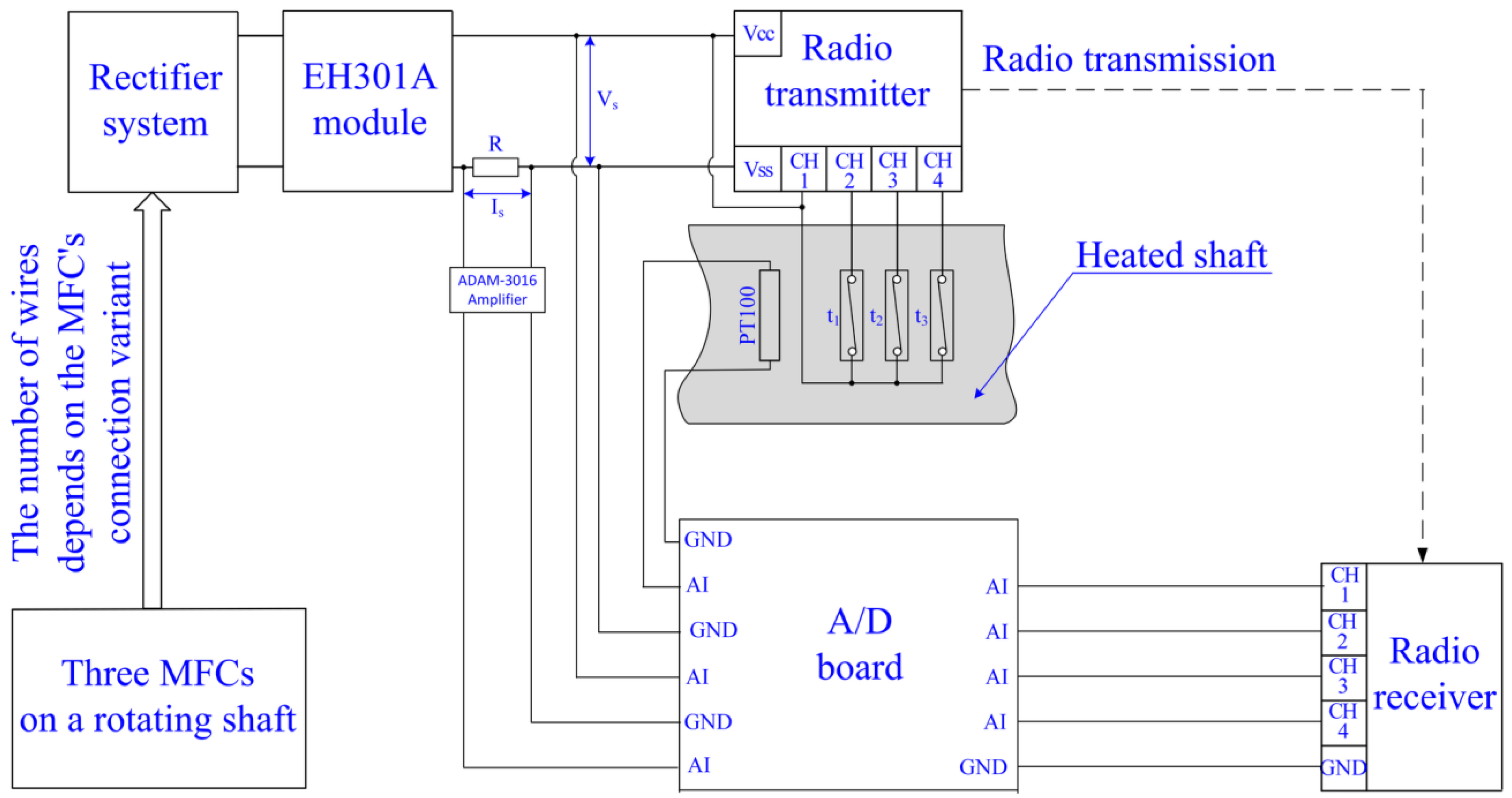
2.3. Measurement System

In the laboratory experiments, the following variables were measured: supply voltage of radio transmitter, supply current of radio transmitter, shaft temperature, and response of the radio receiver. The diagram of the measurement system is shown in Figure 5.
Equipment used in the measurement system:
  • A DaqBoard2000 A/D board produced by IOtech was used in the experiments. The parameters of the board were resolution: 16 bit, max frequency: 200 kHz, measuring range: ±10 V, accuracy: 0.0015%, reading: ±0.005% of range, and input resistance: 20 MΩ;
  • A resistor of 1 Ω with accuracy equal to 0.1% and an ADAM-3016 amplifier produced by Advantech were used to measure the current. The parameters of the amplifier were gain: 1000 and accuracy: 0.1% of range;
  • A load cell and an ADAM-3016 amplifier were used to measure the force. The parameters of the load cell were measuring range: 1000 N and accuracy: 0.1%;
  • A PT100 sensor was used for wired measurement of the temperature.

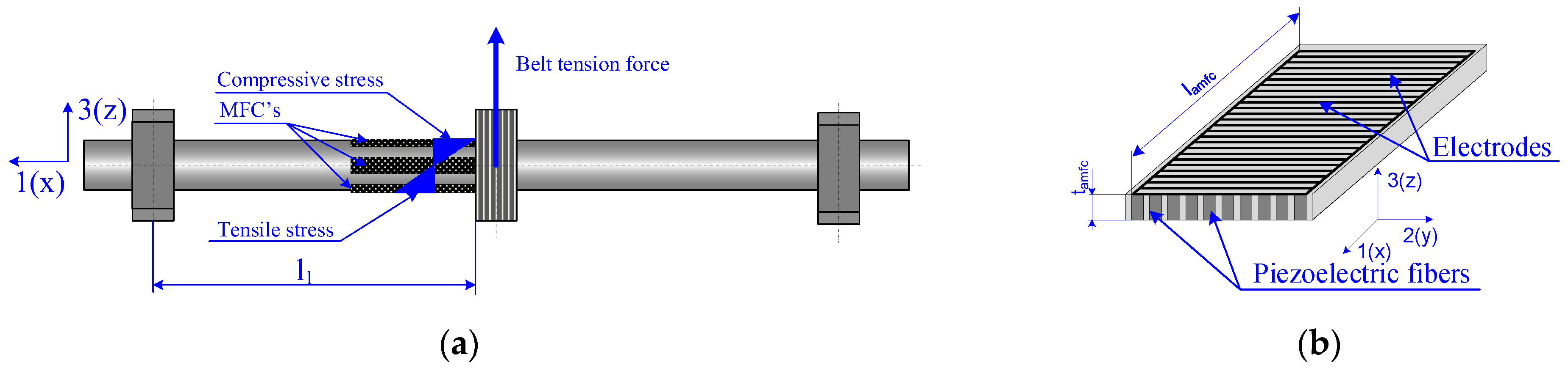
3. Energy Harvesting from Rotating Shaft Based Piezoelectric Materials

The constitutive equations are the basis for the mathematical description of energy conversion in piezoelectric materials [24]:
S p ( t ) = s pq E T q ( t ) + d pk E k ( t ) D i ( t ) = d iq T q ( t ) + ε ik T E k ( t )
where S is the strain, T is the stress, E is the electric field, D is the electric displacement, sE the compliance constant under constant electric field, d is the piezoelectric constant, and εT is the permittivity under constant stress. The operation of a typical belt transmission causes cyclical bending of the driven shaft. The belt tension force generated alternating compressive and tensile stresses in the rotating shaft along axis 1 (Figure 6a). The maximum tensile or compressive stresses in the individual MFC patch occurred when this MFC patch was in the direction of the action of the belt tension force (axis 3 in Figure 6a). Considering that the shaft was rotating, tensile and compressive stress were alternately generated in the individual MFC patches in the direction of axis 3.
Considering the known structure of the P2 type MFC composite, the polarization of the piezoelectric fibers was in the direction of axis 3 (Figure 6b). On the basis the above-described conditions, the constitutive equations take the form:
S 1 ( t ) = s 11 E T 1 ( t ) + d 31 E k ( t ) D 3 ( t ) = d 31 T 1 ( t ) + ε 33 T E k ( t )
The second equation from the system of Equation (2) describes the conversion of mechanical energy into electrical energy. Dependences that describe the relation among electrical variables are known as follows:
E ( t ) = V p ( t ) t a m f c i p ( t ) = w a m f c l a m f c dD ( t ) dt
After substituting (3) into the second equation from (2) and transforming, the formula for the current generated by the MFC patch no “i” was obtained as follows:
i pi ( t ) = d 31 w amfc l amfc dT 1 i ( t ) dt ε 33 T w amfc l amfc t amfc dV pi ( t ) dt
where ipi is the electric current generated by the MFC patch no “i”, Vp is the voltage generated by the MFC patch, wamfc is the width of the active part of the MFC patch, tamfc is the thickness of the piezoelectric fibers in the MFC patch, and lamfc is the length of the active part of the MFC patch. The average value of stress generated in one MFC patch depends on where the patch is glued on the shaft surface. This stress can be calculated from this formula:
T 1 i ( t ) = 1 l amfc l 1 l amfc l 1 M bi ( x ) Y mfc W z Y s dx
where l1 is the distance between the bearing and the grooved pulley, Mb is a bending moment into the MFC patch, Ymfc is the Young modulus of the piezoelectric fibers, Ys is the Young modulus of the shaft material, and Wy is the resistance moment about the neutral axis 3(z). The bending moment and the resistance moment are calculated as follows:
M bi ( x ) = F bti sin ( 2 π ft ) 2 x
W z = π d so + t mfc 4 d sc 4 32 d so + t mfc
where f is the rotation speed of the shaft, t is the time, Fbt is the force acting on the shaft from the transmission belt, x is the distance from the grooved pulley, dso is the external diameter of the shaft, dsc is the internal diameter of the shaft, and tmfc is the overall thickness of the MFC patch. After substituting (5)–(7) into (4) and transforming, the formula for the current generated by the MFC patch no “i” was obtained as follows:
i pi ( t ) = 16 d 31 w amfc l amfc d so + t mfc l 1 l amfc 0.5 l amfc 2 Y mfc π d so + t amfc 4 d sc 4 l amfc Y s d F bti sin 2 π ft dt ε 33 T w amfc l amfc t amfc dV pi ( t ) dt
Based on (8), the current waveform generated by the MFC patch no. “i” depends on
  • The piezoelectric constant of MFC patch;
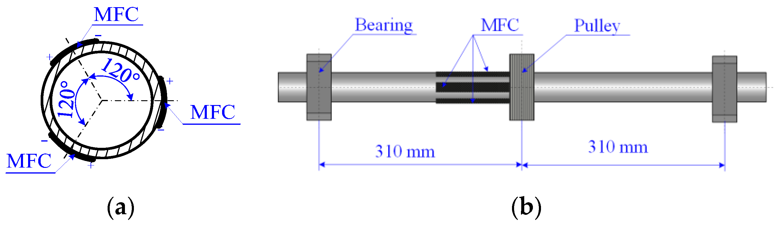
  • The dimensions of active part of MFC patch;
  • The dimensions of rotating shaft;
  • The value of the force acting on the shaft from the transmission belt;
  • The shaft’s rotational speed.
  • The number of these factors can be reduced by replacing the force acting on the shaft and the shaft dimensions by the stresses generated in the shaft by this force at these shaft dimensions (as shown in (5)). This allows the obtained results to be generalized to shafts of any dimensions and any transverse force loading. Considering these conclusions, the courses of the variables determined in the laboratory experiments were determined as a function of stress in the rotating shaft and as a function of the rotational speed of this shaft for selected values of the dimensions of the piezoelectric composite.

4. Results and Discussion

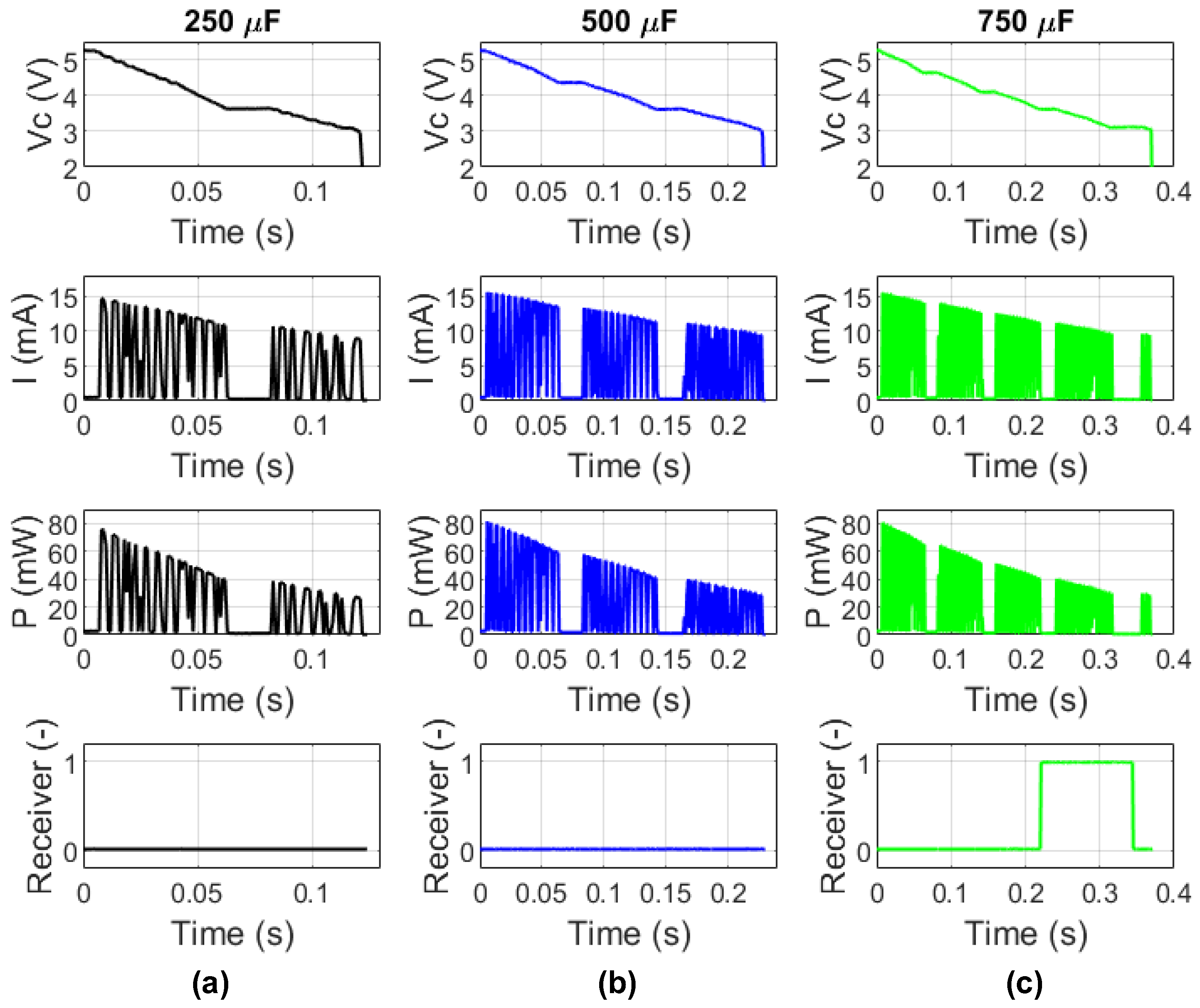
4.1. Selection of the Storage Capacitor

A capacitor was used in this research to store the harvested energy. The selection of the storage capacitor capacitance was an important issue because the value of the energy stored in it had to be large enough for the radio transmitter to send a data packet that would be correctly received by the radio receiver. Too small a storage capacitor capacitance could have caused the radio transmitter to turn on, but without sending full information about the status of the radio transmitter inputs, which would be treated by the radio receiver as incorrect information. On the other hand, too large a storage capacitor capacitance would lead to an increase in the time needed to charge it. To select the minimum value of the capacitor capacitance that is sufficient for correct data transfer, the dependencies of the capacitor charging time to a voltage of 5.2 V (in accordance with the EHO301 A specification) as a function of the capacitor capacitance were determined. Five laboratory experiments were conducted in which the storage capacitor was first charged to 5.2 V and then the EHO301 A module switched on the radio transmitter until the voltage across a storage capacitor dropped to 3.1 V. After switching on the power supply voltage, the radio transmitter was sending a packet of bit-coded data to the radio receiver containing the radio receiver’s address and the state of the inputs of the radio transmitter.
The radio receiver, after receiving the correct data packet, switched on the digital outputs installed in it according to the state of the inputs of the radio transmitter. Figure 7 and Figure 8 show a comparison of the courses of the supply voltage of the radio transmitter, the supply current of the radio transmitter, the supply power of the radio transmitter, and a response of the radio receiver for five storage capacitor capacitances. The capacitor capacitances were varied using a decade of 10% accuracy class capacitors, with the actual capacitance measured using an LCR-916 meter produced by GW Instek. The power supply of the radio transmitter was calculated as the product of voltage and current. Considering that the current required to operate the PT2262 module is less than 2 mA, the power supply of the radio transmitter corresponds almost entirely to the power of the radio signal. All tested capacitor capacities were sufficient to send at least one data packet by the radio transmitter; however, for the capacitor capacities of 250 μF and 500 μF, no radio receiver response was recorded. For the capacitor capacity of 500 μF, the radio receiver response appeared sporadically, which means that the radio signal strength was at the minimum limit. For the capacities of 750 μF and greater, the radio receiver response was recorded in each experiment. To determine the minimum capacitor capacity, detailed experiments were conducted in which the capacitor capacity was changed every 10 μF. Based on the results of these experiments, it was found that the minimum capacitor capacity at which the radio receiver response was recorded each time the radio transmitter was switched on was 560 μF. To ensure stable operation of the radio transmitter—radio receiver system, the capacitor capacity was assumed to be equal to 750 μF.
This capacity of the storage capacitor made it possible to maintain a compromise between the certainty of transmitting correct data from the thermal fuses to the radio receiver while ensuring relatively short times between subsequent data transmissions. The shorter the time between data transmissions, the larger the monitoring sensitivity of the tested system. In other words, the smaller the capacitance of the storage capacitor, the larger the monitoring sensitivity of the tested system. On the other hand, the larger the capacitance of the storage capacitor, the greater the robustness to disturbances of the tested system.

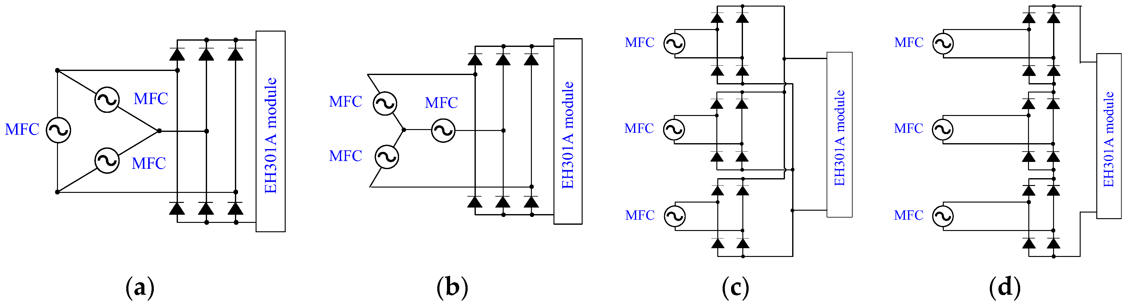
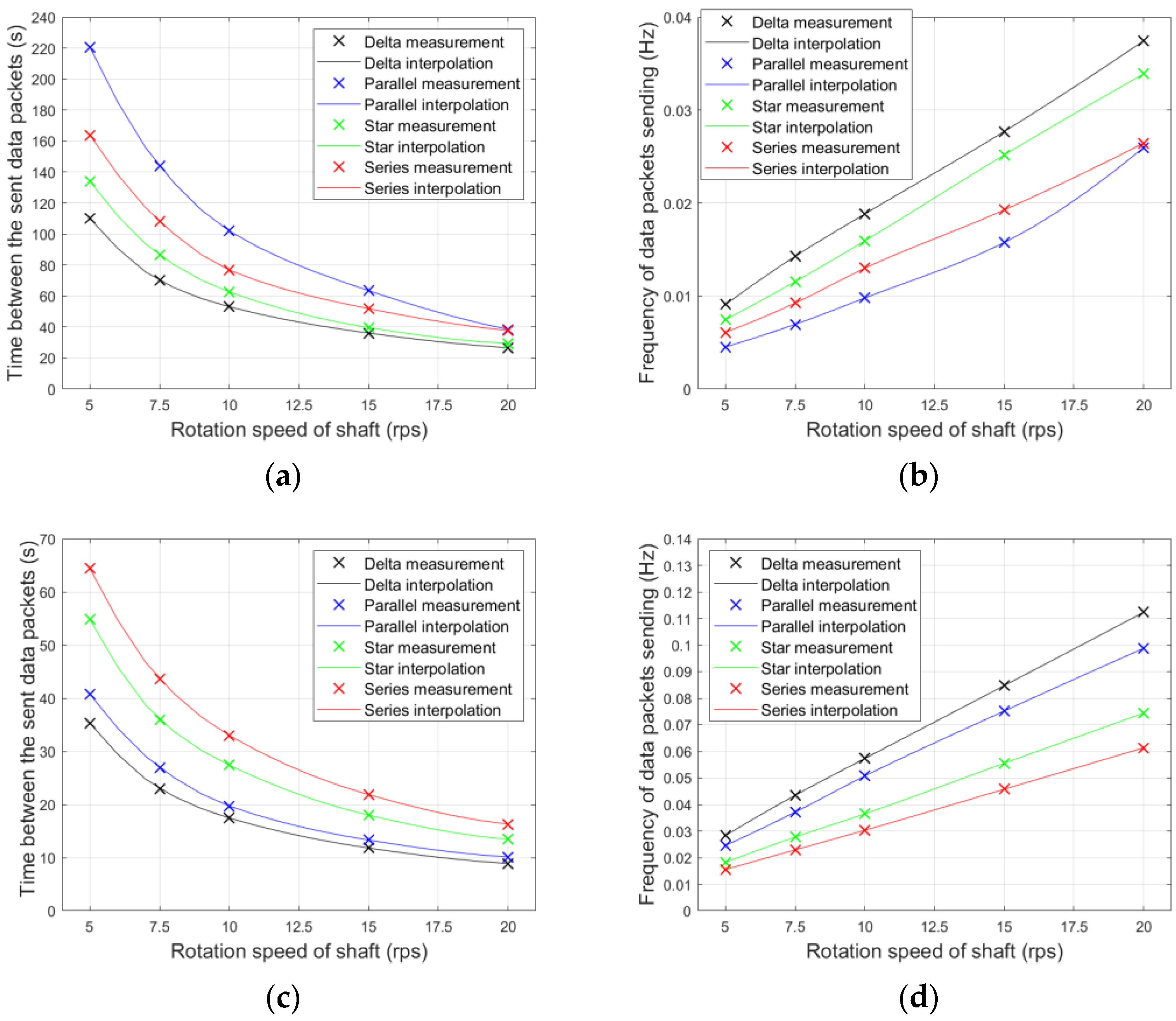
4.2. Selection of the MFCs’ Connection

Three MFC patches were glued on the shaft circumference parallel to the shaft axis every 120°. Such arrangement of MFCs meant that when the shaft was rotating and loaded with the bending force, the MFCs generated sinusoidal voltages, also shifted relative to each other by 120°. The purpose of this experimental research in this stage was to determine of the dependence between the capacitor’s charging time (the period between subsequent transmitter activations) and the connections of the MFC patches at different values of the shaft bending force and at different values of the shaft rotational speed. The rotating shaft was loaded with a bending force, which was measured using a load cell in laboratory experiments. The bending force of 100 N, 125 N, 150 N, 225 N, and 300 N corresponded to the average stress amplitudes on the shaft surface at the place of gluing the MFC, which were given in the Table 1.
The dependence of the capacitor charging time to a voltage of 5.2 V (the threshold of switching on the voltage to the radio transmitter by the EH301 A module) and the switching frequency of the radio transmitter is shown in Figure 9. The research results showed that the frequency of data sent by the radio transmitter was proportional to the stress amplitude, while the time between subsequent data transmissions varied hyperbolically.
The most advantageous connection (the highest frequency of radio transmitter switching on) was the delta connection for stress amplitude above about 13 MPa. However, for stress below about 13 MPa, the star connection was better.
The frequency of radio transmitter activations was proportional to the shaft rotation speed. In the entire range of tested rotational speeds, the most favorable result (the shortest activation times) was obtained for the delta connection (Figure 10).
For stress amplitudes above 15 MPa and all of the rotation speeds of the shaft, an application of a delta connection of MFC patches enabled achieve a shortest time between the sent data packets. Below 15 MPa, the star connection of MFC patches enabled the shortest time between the sent data packets.

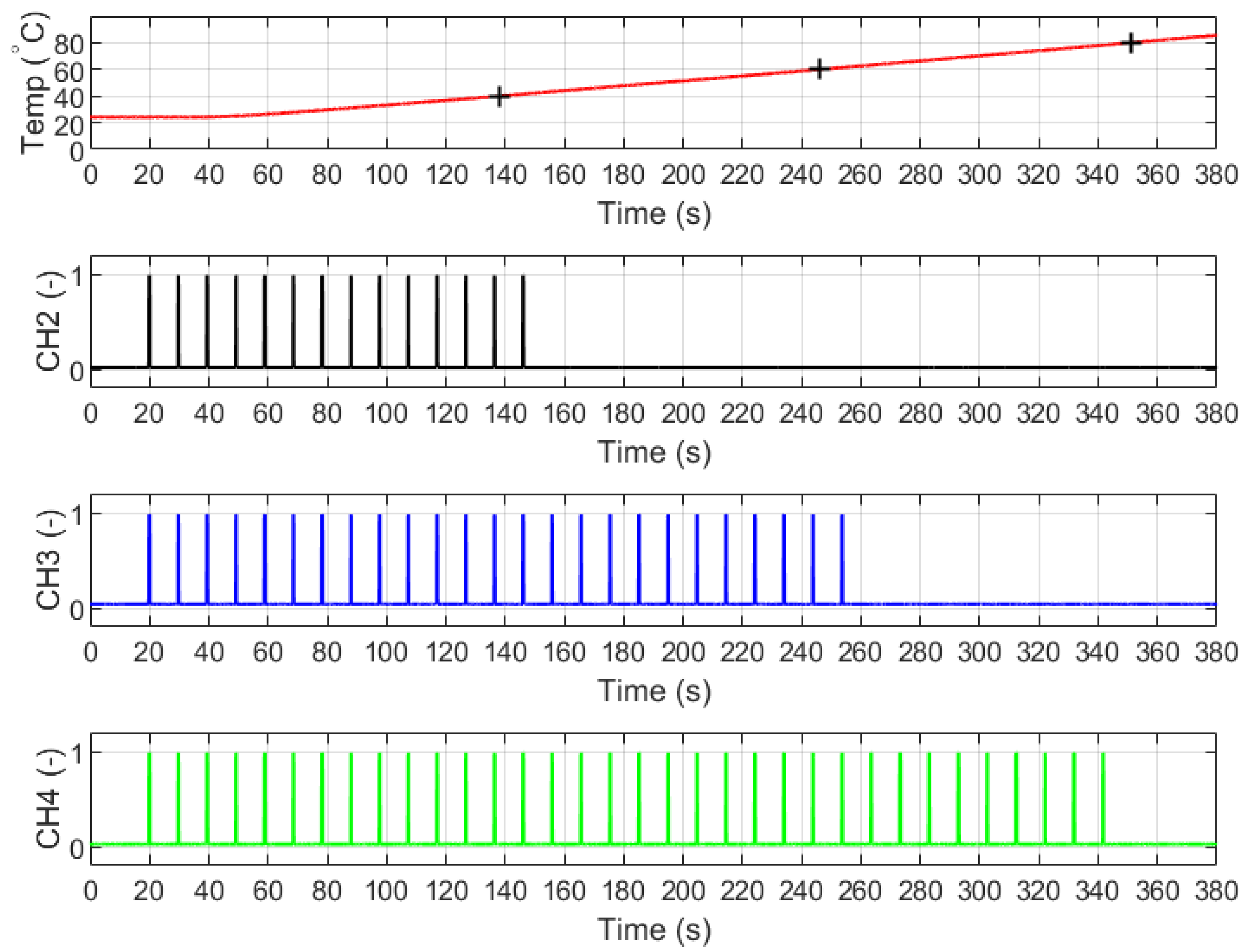
4.3. Operating of Wireless Temperature Monitoring

Figure 11 shows the results of an experiment in which the performance of wireless temperature monitoring powered by harvested energy.
Three thermal fuses with nominal contact opening temperatures of 40, 60, and 80 °C were used in the wireless monitoring. The operation of these fuses, in an experiment presented in Figure 11, was as follows: if the temperature was less than 40 °C, all thermal fuses were closed, which corresponded to the state “1” on all radio receiver channels (CH2, CH3, and CH4), after exceeding the shaft temperature of 41.2 °C, a response was recorded on channel 2 (CH2); after exceeding the temperature of 62.3 °C, a response was recorded on channel 3 (CH3); and after exceeding the temperature of 78.8 °C, a response was recorded on channel 4 (CH4). The difference in the radio receiver response in relation to the nominal temperature thresholds of the thermal fuses (40, 60, and 80 °C) resulted from errors in the thermal fuses themselves, which, according to the manufacturer’s characteristics, can be ±5 °C, and from the delay in transmitting data by the radio transmitter, which depends on the capacitor’s charging time to 5.2 V. The proposed system did not allow for precise determination of the shaft temperature, but it did allow for determining the range of the shaft temperature: below 40 °C, between 40 and 60 °C, between 60 and 80 °C, or above 80 °C. The proposed system can be used to monitor the machine condition and not to measure temperature, so a measurement error of ±5 °C may be acceptable.

5. Conclusions

This paper presents a wireless monitoring of shaft temperature that is powered by electrical energy obtained by piezoelectric energy harvesting from a rotating shaft. The main components of this monitoring are three MFC patches, three thermal fuses, a system for storing and distributing the harvested energy, and a radio transmitter. The most important conclusions:
  • There are three parameters that influence the frequency of sending data packets by the presented wireless temperature monitoring: (1) amplitude of stress in the rotating shaft, (2) rotation speed of the shaft, (3) and the capacity of a storage capacitor;
  • The capacity of a storage capacitor depends on the one hand on the need to send a full data packet, and on the other hand on the need to send data packets as often as possible. It is possible to determine the minimum capacitance of the storage capacitor at which a full data packet is sent. Considering that the larger the capacitance of the capacitor, the longer the time between sending data packets, the capacitance of the capacitor should be slightly larger than the minimum for correct sending of a full data packet;
  • A delta connection of MFC patches enables the fastest capacitor charging and therefore the shortest time between the sent data packets in cases of larger values of shaft rotation speed and larger values of shaft stress amplitude. For lower values of these quantities, the star connection of MFC patches becomes a better choice for achieving the shortest time between the sent data packets. For known dimensions of the active part of the MFC patches and the known rotational speed of the shaft, the threshold of stress amplitude in the shaft can be determined, above which the delta connection will be more effective.
The costs of building the presented wireless monitoring system are higher than the costs of such a system using a battery as a power supply. However, the advantage of the monitoring system proposed in this article is its lower operating cost in comparison to the battery power supply. In the case of the battery power supply, the need for a continuous power supply of the monitoring system (current consumption of approx. 10 mA) will cause rapid battery discharge. Therefore, the use of battery power requires the use of a system that would manage periodic communication and the sleep mode of the system, which is necessary to increase the battery life. The cost of replacing the battery and the cost of interruptions in the operation of the monitored machine should also be considered (battery replacement would be possible only after the machine is stopped). In the case of machines operating continuously, the cost of an unplanned stop could be many times higher than the cost of the monitoring system.

Author Contributions

Conceptualization, P.M. and D.G.; methodology, P.M. and D.G.; investigation, P.M. and D.G.; writing—original draft preparation, P.M. and D.G.; writing—review and editing, P.M. and D.G. All authors have read and agreed to the published version of the manuscript.

Funding

This research was funded by the AGH University of Krakow within the scope of the Research Program No. 16.16.130.942.

Institutional Review Board Statement

Not applicable.

Informed Consent Statement

Not applicable.

Data Availability Statement

Data is contained within the article.

Conflicts of Interest

The authors declare no conflicts of interest.

Symbols and Abbreviations

The following symbols and abbreviations are used:
SStrain
TStress
DElectric displacement
EElectric field
sECompliance constant under constant electric field
εTPermittivity under constant stress
ipElectric current generated by MFC patch
VpVoltage generated by MFC patch
wamfcWidth of active part of MFC patch
tamfcThickness of piezoelectric fibers in MFC patch
lamfcLength of active part of MFC patch
l1Distance between bearing and the grooved pulley
MbBending moment into MFC patch
YmfcYoung modulus of piezoelectric fibers
YsYoung modulus of shaft material
WyResistance moment about the neutral axis
FbtForce acting on the shaft from the transmission belt
dsoExternal diameter of shaft
dscInternal diameter of shaft
fRotation speed of shaft
MFCMacro Fiber Composite
A/DAnalog/Digital
RFRadio Frequency
IFInfrared

References

  1. Jiao, P.; Egbe, K.J.I.; Xie, Y.; Matin Nazar, A.; Alavi, A.H. Piezoelectric sensing techniques in structural health monitoring: A state-of-the-art review. Sensors 2020, 20, 3730. [Google Scholar] [PubMed]
  2. Zhang, C.; Mousavi, A.A.; Masri, S.F.; Gholipour, G.; Yan, K.; Li, X. Vibration feature extraction using signal processing techniques for structural health monitoring: A review. Mech. Syst. Signal Process. 2022, 177, 109175. [Google Scholar]
  3. Butler, Q.; Ziada, Y.; Stephenson, D.; Andrew Gadsden, S. Condition monitoring of machine tool feed drives: A review. J. Manuf. Sci. Eng. 2022, 144, 100802. [Google Scholar]
  4. Tonks, O.; Wang, Q. The detection of wind turbine shaft misalignment using temperature monitoring. CIRP J. Manuf. Sci. Technol. 2017, 17, 71–79. [Google Scholar]
  5. Mian, T.; Choudhary, A.; Fatima, S. Multi-sensor fault diagnosis for misalignment and unbalance detection using machine learning. IEEE Trans. Ind. Appl. 2023, 59, 5749–5759. [Google Scholar]
  6. Ji, J.; Yan, B.; Xiao, B.; Wei, Y.; Sun, C.; Ding, M. Design, construction and modeling of a small-scale high temperature field rotor test rig. Case Stud. Therm. Eng. 2023, 49, 103279. [Google Scholar]
  7. Nembhard, A.D.; Sinha, J.K.; Pinkerton, A.J.; Elbhbah, K. Combined vibration and thermal analysis for the condition monitoring of rotating machinery. Struct. Health Monit. 2014, 13, 281–295. [Google Scholar]
  8. Klemme, H. Heat exchangers for liquid-free cooling of rotating shafts. CIRP Ann. 2023, 72, 361–364. [Google Scholar]
  9. Hasegawa, T.; Kawashima, N. A new technique to measure the temperature of a rotating motor shaft. Appl. Therm. Eng. 2009, 29, 317–323. [Google Scholar]
  10. Kovacs, A.; Peroulis, D.; Sadeghi, F. Early-warning wireless telemeter for harsh-environment bearings. In Proceedings of the SENSORS, 2007 IEEE, Atlanta, GA, USA, 28–31 October 2007; pp. 946–949. [Google Scholar]
  11. Zhou, X.; Zhang, H.; Hao, X.; Liao, X.; Han, Q. Investigation on thermal behavior and temperature distribution of bearing inner and outer rings. Tribol. Int. 2019, 130, 289–298. [Google Scholar]
  12. Zhang, Z.; Xiang, H.; Tang, L.; Yang, W. A comprehensive analysis of piezoelectric energy harvesting from bridge vibrations. J. Phys. D Appl. Phys. 2022, 56, 014001. [Google Scholar]
  13. Grzybek, D. Piezoelectric generator for the Power Supply of the Monitoring System. In Proceedings of the 2014 15th International Carpathian Control Conference (ICCC), Velke Karlovice, Czech Republic, 28–30 May 2014; pp. 135–138. [Google Scholar]
  14. Safaei, M.; Sodano, H.A.; Anton, S.R. A review of energy harvesting using piezoelectric materials: State-of-the-art a decade later (2008–2018). Smart Mater. Struct. 2019, 28, 113001. [Google Scholar]
  15. Chilabi, H.J.; Salleh, H.; Al-Ashtari, W.; Supeni, E.E.; Abdullah, L.C.; As’arry, A.B.; Rezali, K.A.M.; Azwan, M.K. Rotational piezoelectric energy harvesting: A comprehensive review on excitation elements, designs, and performances. Energies 2021, 14, 3098. [Google Scholar] [CrossRef]
  16. Micek, P.; Grzybek, D. Impact of a connection structure of Macro Fiber Composite patches on energy storage in piezoelectric energy harvesting from a rotating shaft. Energies 2022, 15, 6254. [Google Scholar] [CrossRef]
  17. Huang, Q.; Tang, B.; Deng, L.; Wang, J. A divide-and-compress lossless compression scheme for bearing vibration signals in wireless sensor networks. Measurement 2015, 67, 51–60. [Google Scholar]
  18. Grossi, M. Energy harvesting strategies for wireless sensor networks and mobile devices: A review. Electronics 2021, 10, 661. [Google Scholar] [CrossRef]
  19. Shirvanimoghaddam, M.; Shirvanimoghaddam, K.; Abolhasani, M.M.; Farhangi, M.; Barsari, V.Z.; Liu, H.; Dohler, M.; Naebe, M. Towards a green and self-powered Internet of Things using piezoelectric energy harvesting. IEEE Access 2019, 7, 94533–94556. [Google Scholar]
  20. Le Scornec, J.; Guiffard, B.; Seveno, R.; Le Cam, V.; Ginestar, S. Self-powered communicating wireless sensor with flexible aero-piezoelectric energy harvester. Renew. Energy 2022, 184, 551–563. [Google Scholar]
  21. Wang, Z.; He, L.; Gu, X.; Yang, S.; Wang, S.; Wang, P.; Cheng, G. Rotational energy harvesting systems using piezoelectric materials: A review. Rev. Sci. Instrum. 2021, 92, 041501. [Google Scholar]
  22. EH300/301 Epad® Energy HarvestingTM Modules. Available online: https://www.mouser.pl/datasheet/2/8/EH300-1651600.pdf (accessed on 4 June 2025).
  23. Yang, Y.; Tang, L.; Li, H. Vibration energy harvesting using macro-fiber composites. Smart Mater. Struct. 2009, 18, 115025. [Google Scholar]
  24. Wang, Q.M.; Cross, L.E. Constitutive equations of symmetrical triple layer piezoelectric benders. IEEE Trans. Ultrason. Ferroelectr. Freq. Control. 1999, 46, 1343–1351. [Google Scholar]
Figure 1. Diagram of the laboratory stand.
Energies 18 03620 g001
Figure 2. View of the laboratory stand.
Energies 18 03620 g002
Figure 3. Arrangement of MFCs: (a) View of shaft cross-section; (b) Side view of the shaft.
Energies 18 03620 g003
Figure 4. Connections of MFC patches: (a) delta; (b) star; (c) parallel; (d) series.
Energies 18 03620 g004
Figure 5. Schema of measurement system.
Energies 18 03620 g005
Figure 6. Coordinate system in laboratory experiments: (a) Shaft; (b) MFC type P2.
Energies 18 03620 g006
Figure 7. Supply voltage of radio transmitter, supply current of radio transmitter, supply power of radio transmitter and a response of radio receiver: (a) for 250 μF; (b) for 500 μF; (c) for 750 μF.
Energies 18 03620 g007
Figure 8. Supply voltage of radio transmitter, supply current of radio transmitter, supply power of radio transmitter and a response of radio receiver: (a) for 1000 μF; (b) for 1500 μF.
Energies 18 03620 g008
Figure 9. Intervals in the sending of data packets: (a) in seconds for shaft rotation speed equal to 10 rps; (b); in hertz for shaft rotation speed equal to 10 rps; (c) in seconds for shaft rotation speed equal to 20 rps; (d) in hertz for shaft rotation speed equal to 20 rps.
Energies 18 03620 g009aEnergies 18 03620 g009b
Figure 10. Intervals in the sending of data packets: (a) in seconds for stress equal to 17.363587 MPa; (b); in hertz for stress equal to 17.363587 MPa; (c) in seconds for stress equal to 34.727174; (d) in hertz for stress equal to 34.727174.
Energies 18 03620 g010
Figure 11. Operating of wireless temperature monitoring for stress equal to 34.727174, rotation speed equal to 20 rps, and capacity of storage capacitor equal to 750 μF.
Energies 18 03620 g011
Table 1. Conversion of a bending force into stress.
Bending Force (N)Bending Moment (N × mm)Stress Amplitude (MPa)
10025,00011.575725
12531,25014.469656
15037,50017.363587
22556,25026.045381
30075,00034.727174
Disclaimer/Publisher’s Note: The statements, opinions and data contained in all publications are solely those of the individual author(s) and contributor(s) and not of MDPI and/or the editor(s). MDPI and/or the editor(s) disclaim responsibility for any injury to people or property resulting from any ideas, methods, instructions or products referred to in the content.

