Abstract
This paper deals with an analysis of the operation of switched reluctance machines with a non-uniform air gap. The main focus was on the analysis of the performance of machines with a linearly decreasing air gap. Intensive field calculations made it possible to provide their accurate characteristics, which were then used in simulations of various dynamic states. On this basis, the advantages and disadvantages of machines with a non-uniform air gap were finally discussed from the point of view of applications in efficient high-speed drive systems.
1. Introduction
Switched reluctance machines (SRMs) are an attractive alternative to induction machines and permanent magnet machines in various drive applications. Their very important advantages include a simple design, low price, high power density and reliability. The basics of SRM design, optimization, control and power supply are included, for example, in classic books by T.J.E. Miller [1] and R. Krishnan [2]. The above issues are currently analyzed in many scientific articles, e.g., the review articles [3,4] or book [5].
The purpose of this paper is to analyze the operation of SRMs with a non-uniform airgap, which is a topic that has not been discussed very often or in depth. This is one of the SRM geometry optimization problems which have been analyzed in many excellent articles—however, most of them concern parametric optimization of conventional SRMs (with a uniform airgap) in order to improve their performance, e.g., [6,7,8,9] and the references therein.
Various possibilities of designing SR machines with a non-uniform airgap were presented in book [1] (pp. 27–31). Among other things, the stepped or tapered SRM air gaps are discussed there. This idea was originally described in Byrn’s articles, e.g., [10]; his patents; and also in [11], where the authors intended to reduce the dead zone near the unaligned position of the two-phase SRM. As the authors of [11] claim, “The effect of stepping the airgap is to extend the region of positive inductance variation such that at any position there is a positive dL/dθ for either phase winding”. A stepped-air-gap SRM is characterized by less saturation of the stator and rotor poles as they approach each other.
Different shapes of the stator and rotor poles to reduce the torque ripple were analyzed in [12]. Among other things, the influence of notched poles and slant poles on minimizing the pulsation of the electromagnetic SRM torque is considered here. Control methods of high-speed SRMs with an asymmetric rotor magnetic circuit were discussed in [13]. Different possibilities of rotor deformation in order to obtain SRM self-starting ability are shown in article [14].
Many valuable articles on non-uniform gap SRMs were published by the team led by Jin-Woo Ahn from Busan [15,16,17,18,19,20,21,22,23]. These articles present the performance analysis of SRMs with different stepper and slanted rotors. The summary of this research is the article [20], which presents various variable air-gap rotor structures and their influence on SRM control methods.
Paper [24] presents “a shape optimization framework that can systematically investigate a correlation between the rotor/stator pole shapes and the major performance of the SRM (average torque, torque ripple, etc.)”. In [25,26,27,28], different modifications of the SRM pole shape were also discussed.
In the paper [29], the influence of the non-uniform air gap in the SRM on the values of the radial force and the torque ripple was analyzed. The authors showed that an appropriate change in the shape of the SRM air gap and its power supply causes almost complete elimination of vibrations while increasing the electromagnetic torque.
The authors of the article [30] conducted extensive studies on the influence of different SRM air-gap shapes on the machine torque profile. Article [31] deals with a back-EMF-based sensorless control system of SRMs for high-speed operation, and article [32] presents an optimization method for the pole parameters of variable-gap SRMs.
A procedure similar to changing the shape of the SRM air gap is the modification of the machine’s magnetic core by introducing air barriers into the inner area of its poles [33]. In some articles, modifications of the SRM poles in the axial direction were also considered [12,34]. This has been used to limit SRM vibrations and reduce unfavorable acoustic effects. Some of the key possibilities of the SRM design with a non-uniform air gap are shown in Figure 1.

Figure 1.
Different design possibilities of SRMs with non-uniform air gap: stepped pole (a,b); notched pole (c); slanted pole (d).
In summary, it can be stated that many authors have noticed the benefits of using non-uniform air gaps in SRMs for a long time in order to achieve better operating parameters of these machines, but their articles have never treated this problem comprehensively. In addition, none of the authors have seriously dealt with the problem of the efficiency of high-speed machines with a non-uniform gap, increasing their torque, reducing power losses and reducing the size of the power supply system. The above-mentioned articles analyze specific non-uniform gap SRM solutions (often demonstrating their advantages), but they do not generally analyze the influence of different gap parameters on SRM performance. This is the main goal of this article.
2. Force Generation in Switched Reluctance Machines
The study of the influence of a non-uniform air gap on SRM parameters was carried out using the results of tests on the machine designed and constructed within the Dynastore project [35,36,37]. The Dynastore flywheel is designed as a high-speed energy storage system for events of a short duration, to serve for the local tuning of the medium voltage power grid. The motor/generator system uses a high-speed multipole external rotor SRM/SRG, with a rated power of 2 MW at a speed range between 6000 ÷ 10,000 rpm. The applied advanced inherently stable high-temperature superconducting magnetic bearing system minimizes the stand-by losses while maximizing the bearing stiffness. For the 2 MW external rotor SRM planned in this project, a prototype machine with an internal rotor of 100 kW was built [35,36]. The basic data of the prototype machine were as follows: number of stator/rotor poles—24/16, stator outer diameter—310 mm, rotor outer diameter—200 mm, air gap—1 mm, stator/rotor teeth width—13/13 mm, max. number of revolutions—6000 1/min. The prototype tests performed were comprehensive and the calculations were thoroughly verified by measurements performed on the prototype machine, which enabled the creation of highly accurate computational instrumentation which was then used for the analysis of SRMs with a non-uniform air gap.
All field calculations shown in this article were performed with the proprietary finite element method program. This program enables extremely accurate field calculations of the analyzed SRM configurations for a very fine mesh of finite elements—calculations with commercial programs are much less accurate, which makes it difficult to correctly determine the values of SRM inductances and their derivatives, which are particularly sensitive to calculation errors. The results of numerical calculations for uniform gaps were verified by measurements—it can therefore be safely assumed that the results for non-uniform gaps are correct.
The tested SRM is shown in Figure 2a,b, and Figure 2c,d gives the magnetic field distribution in the aligned and unaligned positions of the SRM rotor.
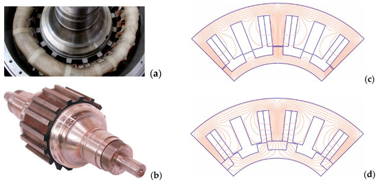
Figure 2.
Prototype of 100 kW, 24/16 SRM (a); rotor of SRM (b); magnetic field distribution in aligned position (c); magnetic field distribution in unaligned position (d).
Due to the lack of magnetic coupling between SRM phases, each phase can be considered independently. The voltage equation for one phase of the SR machine can be written as follows:
where u—external voltage at the terminals, R—resistance, i—current, t—time, Φ—magnetic flux-linkage.
The above equation can also be written as follows:
where —self-inductance of the phase coil, θ—rotation angle, ω—angular velocity.
For low-speed operation, the source voltage has a greater magnitude than the back-EMF ; for high-speed operation, the back-EMF can be greater than the source voltage, which causes obvious difficulties in the correct supply and control of the SRM.
The instantaneous value of the force (torque) acting on the rotor depends on the derivative of the winding inductance with respect to the displacement angle and the square of the current:
where C is a specific proportionality coefficient.
The mean value of the force for the period and for commutation time can be written as follows:
The power losses in the SRM winding can be determined using the following formula:
The source power for one period (for a constant supply voltage value) is written as follows:
SRMs are voltage-supplied [38], and when powering a high-speed SRM, it is not possible to change the supply voltage. In the initial phase of commutation, the current in the machine winding is small because its inductance is large, which is disadvantageous due to the value of the generated force at this time. These forces can be increased by increasing the value of the current in the machine winding, which is the effect of reducing the winding self-inductance. The reduction of the self-inductance value of the SRM winding in the initial part of the commutation period can be realized in a machine with a non-uniform air gap value [39]. The idea of this solution is shown in Figure 3.

Figure 3.
Magnetic field distribution in a linear SRM model with a non-uniform air gap.
Due to the shape of the air gap in the SRM from Figure 3, the values of the self-inductance of the machine winding are slightly smaller than in the case of a constant gap, especially at the moment when the rotor pole slides over the stator pole. This allows a higher current to flow through the machine windings while maintaining a large gradient of inductance changes, which leads to an increase in forces. The reduced inductance values and thus lower time constants support a fast increase in the current needed for high dynamic applications, especially at high speeds. The non-uniform air gap causes an additional reduction in the saturation of the magnetic circuit, which is beneficial in terms of the force values and reduction in torque pulsations.
The shape of the SRM air gap can be precisely determined depending on the specific design requirements [39,40,41,42,43,44]. In order to investigate the effect of a non-uniform air gap on the winding inductance and, consequently, on the value of the mean force generated in the machine, an SRM with a linearly decreasing air gap was analyzed for different skew angles α (Figure 4).
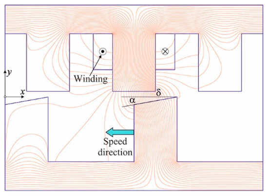
Figure 4.
Magnetic field distribution in a linear SRM model with a linearly decreasing air gap: δ—nominal air gap, α—skew angle.
The calculations were performed for the basic SRM structure (linear model): 3 stator poles and 2 rotor poles, defining the periodicity conditions of the solution in the x-direction. The dimensions of the linear model were as follows: width of the stator and rotor poles—30 mm, distance between stator poles—30 mm, distance between rotor poles—60 mm, nominal air gap—2 mm, nominal current density in the windings—15 A/mm2. These are the main SRM data of the Dynastore project.
The calculations used the magnetization curves of different SRM construction materials. These materials have a large impact on the calculation results of the energy conversion efficiency in SRMs, causing different saturation of the magnetic circuit at the same current excitations. Figure 5a shows the magnetization curves of various magnetic materials used in the construction of SRMs. In this paper, the main focus was on the ST-37 steel (curve 4), but the influence of other magnetization curves on the results was also investigated.
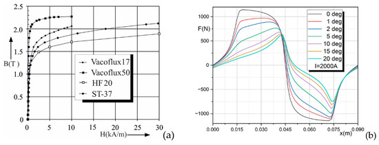
Figure 5.
B-H curves used for calculations (a); force as a function of displacement for the current in windings of 2000 A for different values of skew angle α (b).
The Maxwell Stress Tensor method was used to determine the forces acting between the stator and rotor of the SRM. Figure 5b shows the relationship between force and displacement for the selected current in the windings and different values of the angle α. These calculations were performed using the finite element method in a two-dimensional SRM model (the results for the SRM base structure from Figure 4 for a length of one meter in the axial direction). The actual length of the SRM in the axial direction lz must be taken into account in the final simulations.
To generate torque in the SRM, the first (positive) part of the characteristics from Figure 5b is used. For the displacement x = 0.07 m, a strong minimum of the force function is noticeable. This is related to the exit of the deformed rotor pole from under the stator pole—this part of the characteristic is not used for generating forces. To smooth this curve, a smaller deformation of the rotor pole should be applied, as in Figure 1a. For such a configuration, the beneficial effects of supporting current commutation for high rotational speeds are reduced, and therefore, in order to better illustrate the effects of air gap deformation, a more deformed gap is analyzed.
For a non-uniform gap, the zero force point position shifts compared to the constant-air-gap SRM (see Figure 5b), which must be taken into account when feeding the machine. The amplitude of the force for angles α greater than zero is smaller than for a uniform gap at the same current in the winding; however, with the voltage supply of the machine for a given rotor position, a larger current will flow, which makes it possible to obtain a higher average force value.
The inductance per meter length L of the SRM winding carrying a current I with the density J is calculated by determining the value of the magnetic co-energy from the following formula:
where A is the magnetic vector potential obtained by finite element calculations, S is the winding area and n is the number of the SRM winding turns [45]. In the case discussed, there are two galvanically connected current areas with different self-inductances.
Figure 6a shows the inductance values of the SRM winding as a function of displacement for five different values of the angle α, and Figure 6b shows the derivative of these inductances with respect to the displacement (n = 1).
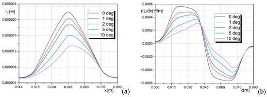
Figure 6.
Inductance of the SRM winding as a function of displacement for five different values of the angle α (a); derivative of the inductance (b).
To accurately determine the derivatives from Figure 6b, the Akima approximation of the winding inductance dependency was used [46]. The Akima interpolation method provides an excellent procedure for the smooth curve fitting of experimental and calculation data, which enables very accurate calculation of the corresponding derivatives. This method was also used for precise interpolation of two-dimensional inductance distributions in order to solve Equation (2) with the highest accuracy (see the next section).
The inductance of the SRM winding for angles α greater than zero is smaller than for a uniform gap at the same winding current, which allows the flow of currents with higher values. At the same time, the value of the inductance gradient decreased, which resulted in a partial reduction of the driving forces.
3. Power and Dynamic State Analysis of SRM
This chapter presents the solution of Equation (2) for the linear SRM model. In this case, this equation is written as follows:
where is the rotor speed.
3.1. SRM Characteristics for Different Values of Skew Angle α
The linear model data from Figure 4 were assumed as follows: v = 90 m/s, T = 1 ms, U = 1000 V, R = 1 Ω, n = 20, S = 200 mm2, J = 10 A/mm2, lz = 1 m. This corresponds to a speed of approximately 55 1/s for a rotor radius of 0.26 m. The geometric data of this SRM model correspond to the parameters of the real machine from the Dynastore project; the remaining values were chosen for a better presentation of the occurring phenomena.
Figure 7 shows the values of the forces generated (a) and the self-inductances of the SRM’s winding (b) in the configuration of Figure 4 for the skew angle α = 0 deg. The first half of the period T (x = 0 ÷ 45 mm) is used to generate forces (from the unaligned to the aligned position).
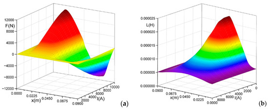
Figure 7.
Force values (a) and inductance values (b) for skew angle α = 0 deg.
Figure 8 illustrates the values of the generated forces (a) and self-inductance of the SRM windings (b) for a skew angle of α = 10 deg.
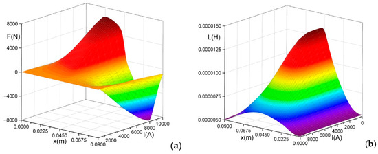
Figure 8.
Force values (a) and inductance values (b) for skew angle α = 10 deg.
Both the force values and the inductance values are smaller for a larger skew angle than for a constant gap for the same current values in the windings due to the larger resultant air gap. The dependences and from Figure 8 are not symmetrical about the coordinate x = 45 mm, which is also visible in Figure 5b and Figure 6. Accurate determination of derivatives in Equation (9) for any values of the winding current and the rotor position required the use of a very dense finite element mesh. These functions were finally approximated using the two-dimensional Akima algorithm. This can be also determined in MATLAB R2024a which is much less accurate and introduces significant numerical errors into the calculations. Figure 9 shows the derivatives of the inductance of the SRM windings of machines with the skew angles α = 5 deg and α = 10 deg for different values of the winding current.
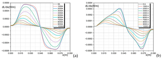
Figure 9.
Derivative of inductance as function of displacement for different currents in windings and skew angle α = 5 deg (a); α = 10 deg (b).
3.2. SRM Dynamic States
The block diagram of the voltage-powered SRM is shown in Figure 10. The basic calculation blocks corresponding to the individual components of Equation (9) are marked here, as well as the Lookup Tables containing values of the forces, inductances and their derivatives of the SRM windings calculated using the finite element method.
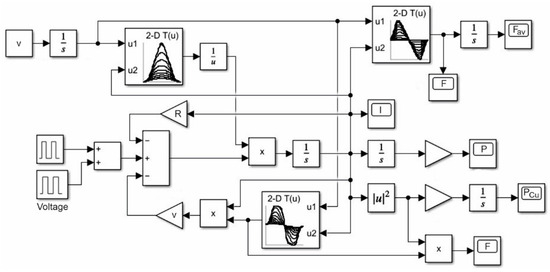
Figure 10.
SRM computational model in MATLAB/Simulink.
The SRM in Figure 10 is powered by a system of two rectangular pulse generators, allowing the modeling of various SRM power supply states, including negative voltages. For skew angles greater than zero, the voltage must be switched on with a delay resulting from the shift of the zero-force point in relation to the configuration with a uniform air gap (see Figure 6). For α = 5 deg, this delay is 1.5 mm, and for α = 10 deg, it is −3.0 mm, which corresponds at a speed of 90 m/s to a time shift of 0.0167 ms and 0.0333 ms, respectively.
Figure 11a shows the current in the SRM winding as a function of time at a speed of 90 m/s and for different values of the skew angle α when the SRM is powered for a time T/2, Figure 11b shows the values of the SRM winding inductances as a function of time and Figure 11c shows their derivatives.

Figure 11.
Current in SRM winding (a); winding inductance (b); derivative of winding inductance (c) for three different values of angle α: α = 0 deg (yellow), α = 5 deg (red) and α = 10 deg (blue).
As can be seen from Figure 11a, the current values in the SRM windings are the same up to the moment t = 0.1 ms for all three configurations. For longer times, the current in the windings of machines with a non-uniform air gap is higher than in the machine with a constant air gap. This causes an increase in the forces despite the reduced winding inductance gradients. The inductance of the winding of the machine with a uniform air gap is much larger than the inductance of the SRM with skew angles greater than zero, which allows for the flow of currents with higher values for these configurations. At the same time, the value of the inductance derivative is larger for α = 0 deg, which causes an increase in the forces for a constant air gap. These effects compensate for each other at a certain point, causing the forces in the configurations with the non-uniform air gap to be greater from that point on. For this reason, in practical applications, the aim should be to increase the commutation time .
Figure 12a shows corresponding force dependencies. These forces can also be determined directly in Simulink using formula (3)—the results are identical to those obtained using the Maxwell Stress Tensor. Figure 12b gives the time dependence of the mean force (formula (4)) and Figure 12c shows the force generation efficiency factor (formulas (4) and (6)).

Figure 12.
Force (a); mean force (b); force generation efficiency factor (c) for three different values of angle α: α = 0 deg (yellow), α = 5 deg (red) and α = 10 deg (blue).
As can be seen from Figure 12b, the mean force values for the 5 deg and 10 deg skews starting from ca. t = 0.38 ms are greater than for the uniform gap. For α = 10 deg, a decrease in the force values is obtained in comparison with the dependencies for α = 5 deg, which means that an excessive skew can lead to worse results. The increase in the force value takes place for a time of approximately 0.4 ms, which is not favorable from the point of view of applications, but this is an extremely important observation that provides a basis for searching for appropriate SRM geometries, for which the value of the mean force will be greater for non-uniform gaps even earlier.
The generation of higher forces for a non-uniform air gap obviously takes place with an increase in the source power (Figure 12c) and an increase in heat power losses due to the higher current values. For higher rotational speeds, the relationships given here are similar—the positive effect of a non-uniform gap on the force values is then more noticeable due to the reduction of the back-EMF (see Equation (2)).
Table 1 shows the mean force values and force generation efficiency factors at different speeds for the commutation time .

Table 1.
Mean force and force generation efficiency factor at different speeds.
As can be seen from Table 1, the values of the mean force are higher for the skew angle of 5 deg and 10 deg than for a uniform gap. Such good results are obtained for the pulse duration t0 = T/2, which is practically not feasible due to the possibility of obtaining braking forces. However, even for the time t0 = 0.4 ms, an increase in the mean force of several percentage points is obtained. For α = 5 deg, slightly better results are obtained than for α = 10 deg. For higher speeds, the configuration with α = 10 deg proves to be better. The force values for α = 10 deg are obtained with a higher energy consumption. This means that in the analyzed case, the optimal skew angle is approximately 4–8 deg—for each designed SRM, the value of the optimal skew should be precisely determined.
All SRM power supply strategies come down to the width modulation of voltage pulses at the machine terminals [1,2,5,13,36,38,47], regardless of the control algorithm used. The following Figure 13 and Figure 14 show sample graphs of the current in the windings, the driving force and the average driving force for two different SRM power supply methods (v = 90 m/s):

Figure 13.
The current in the SRM winding (a); force (b); mean force (c) for three different values of the angle α: α = 0 deg (yellow), α = 5 deg (red) and α = 10 deg (blue) for the first supply mode.

Figure 14.
The current in the SRM winding (a); force (b); mean force (c) for three different values of the angle α: α = 0 deg (yellow), α = 5 deg (red) and α = 10 deg (blue) for the second supply mode.
- Rectangular voltage pulse with an amplitude of 1000 V appearing at t = 0.0 ms and changing its value to −1000 V at moment t = 0.35 ms (in order to reduce the current value in the windings more quickly);
- Seven voltage pulses of 1000 V (period 0.05 ms, pulse width 50% of period).
Applying a negative voltage in the first case at t = 0.35 ms does not cause the current to drop to zero at t = 0.5 ms, which limits the beneficial effects of the non-uniform air gap. It would be necessary to apply an even larger negative voltage here to reduce the current value even faster. This is clearly visible in the second case (without switching on the opposite voltage), in which the current value at t = 0.5 ms is still quite large.
For the SRM configuration analyzed here, some improvement in machine performance was obtained, especially for longer commutation times. The point at which the force values are equal in configurations with a non-uniform air gap can be moved towards shorter times by optimally selecting the geometrical dimensions of the machine (the proportions between the width of the poles and the distances between them, both in the stator and in the rotor). This can be achieved more easily for the SRM configurations from Figure 1a or Figure 1c. However, this requires multiparametric optimization, which makes it difficult to interpret the effect of geometry changes on machine performance. In the analyzed case, there is a change in only one SRM parameter (the rotor pole skew angle), which facilitates the analysis of the effect of the non-uniformity of the air gap on the SRM parameters.
An additional positive effect of using a pole skew, which can be used in high-speed machines, is the reduction of the ripple torque when supplying the SRM with a single voltage pulse (see Figure 12a)—an appropriate skew angle (less than α = 5 deg) should be selected.
4. Conclusions
The considerations presented in this article are of a general nature and their purpose was to draw attention to the phenomenon of facilitating commutation in SRMs by changing the geometry of the air gap. It brings benefits consisting in increasing the SRM torque as well as reducing torque ripple, which significantly reduces machine vibrations. This was confirmed by intensive simulations of different SRM operating conditions for different air gap deformations, speeds, number of winding turns, supply voltage values and types of magnetic material.
The selection of the air gap deformation degree must be made based on various additional criteria, such as available supply voltage, machine geometry, efficiency, torque ripple, etc. In the real machine, the air gap should be constant (partially filled with non-magnetic material), which prevents adverse acoustic effects.
The nonlinearity of the magnetic circuit of the machine affects its parameters similarly to the non-uniform air gap, due to the saturation of some areas near the air gap and the reduction of their magnetic permeability. This effect is more noticeable at low rotational speeds, due to the much higher values of the current in the machine, than at high rotational speeds.
Funding
This research received no external funding.
Data Availability Statement
The original contributions presented in the study are included in the article, further inquiries can be directed to the corresponding author.
Conflicts of Interest
The author declares no conflicts of interest.
References
- Miller, T.J.E. Switched Reluctance Motors and Their Control; Magna Physics Publishing and Clarendon Press: Oxford, UK, 1993. [Google Scholar]
- Krishnan, R. Switched Reluctance Motor Drives: Modeling, Simulation, Analysis, Design, and Applications; CRC Press: Boca Raton, FL, USA, 2001. [Google Scholar] [CrossRef]
- Scalcon, F.P.; Fang, G.; Filho, C.J.V.; Gründling, H.A.; Vietira, R.P.; Nalhid-Mobarakeh, B. A Review on Switched Reluctance Generators in Wind Power Applications: Fundamentals, Control and Future Trends. IEEE Access 2022, 10, 69412–69427. [Google Scholar] [CrossRef]
- Bajpai, D.; Jogi, V.K. Brief History of Switched Reluctance Motor. IOSR J. Electr. Electron. Eng. 2018, 13, 1–25. [Google Scholar] [CrossRef]
- Miller, T.J.E. (Ed.) Electronic Control of Switched Reluctance Machines; Newnes Power Engineering Series; Reed Educational and Professional Publishing: Oxford, UK; Auckland, New Zealand; Boston, MA, USA; Johannesburg, South Africa; Melbourne, Australia; New Delhi, India, 2001; ISBN 0-7506-50737.
- Tekgun, D.; Tekgun, B.; Alan, I. FEA based fast topology optimization method for switched reluctance machines. Electr. Eng. 2022, 104, 1985–1995. [Google Scholar] [CrossRef]
- Barba, P.; Mognaschi, M.E.; Przybylski, M.; Rezaei, N.; Slusarek, B.; Wiak, S. Field-Based Analysis and Optimal Shape Synthesis of Switched Reluctance Motors. In Analysis and Simulation of Electrical and Computer Systems; Lecture Notes in Electrical Engineering; Springer International Publishing AG: Berlin/Heidelberg, Germany, 2018; Volume 452. [Google Scholar] [CrossRef]
- Qiao, W.; Diao, K.; Han, S.; Sun, X. Design optimization of switched reluctance motors based on a novel magnetic parameter methodology. Electr. Eng. 2022, 104, 4125–4136. [Google Scholar] [CrossRef]
- Abunike, C.E.; Okoro, O.I.; Aphale, S.S. Intelligent Optimization of Switched Reluctance Motor Using Genetic Aggregation Response Surface and Multi-Objective Genetic Algorithm for Improved Performance. Energies 2022, 15, 6086. [Google Scholar] [CrossRef]
- Byrne, J.V.; Lacy, J.G. Characteristics of Saturable Stepper and Reluctance Motors. In Proceedings of the IEE Conference on Small Electrical Machines, London, UK, 30–31 March 1976; pp. 93–96, ISBN 0852966962. [Google Scholar]
- El-Khazendar, M.A.; Stephenson, J.M. Analysis and optimisation of the 2-phase self-starting switched reluctance motor. In Proceedings of the ICEM, Munich, Germany, 8–10 September 1986; pp. 1031–1034. [Google Scholar]
- Gan, C.; Wu, J.; Sun, Q.; Kong, W.; Li, H.; Hu, Y. A Review on Machine Topologies and Control Techniques for Low-Noise Switched Reluctance Motors in Electric Vehicle Applications. IEEE Access 2018, 6, 31430–31443. [Google Scholar] [CrossRef]
- Bogusz, P.; Korkosz, M.; Prokop, J. Control method of high-speed switched reluctance motor with an asymmetric rotor magnetic circuit. Arch. Electr. Eng. 2016, 65, 685–701. [Google Scholar] [CrossRef][Green Version]
- Pang, M.; Wang, H.; Zhou, G.; Li, F.; Wei, X.; Zhang, M. Design and Analysis of a Two-phase Permanent-Magnet-Assisted Switched Reluctance Motor. In Proceedings of the 21st International Conference on Electrical Machines and Systems (ICEMS), Jeju, Republic of Korea, 7–10 October 2018. [Google Scholar]
- Lee, D.-H.; Ahn, J.-W. Performance of High-Speed 4/2 Switched Reluctance Motor. J. Electr. Eng. Technol. 2011, 6, 640–646. [Google Scholar] [CrossRef]
- Lee, D.-H.; Pham, T.H.; Ahn, J.-W. Design and Operation Characteristics of Four-Two Pole High-Speed SRM for Torque Ripple Reduction. IEEE Trans. Ind. Electron. 2013, 60, 3637–3643. [Google Scholar] [CrossRef]
- Hieu, P.T.; Lee, D.-H.; Ahn, J.-W. Design and Operation Characteristics of Novel 2-Phase 6/5 Switched Reluctance Motor. J. Electr. Eng. Technol. 2014, 9, 2194–2200. [Google Scholar] [CrossRef]
- Hieu, P.T.; Lee, D.-H.; Ahn, J.-W. High Speed Segmental Stator Type 4/3 SRM: Design, Analysis, and Experimental Verification. J. Electr. Eng. Technol. 2017, 12, 1864–1871. [Google Scholar] [CrossRef]
- Lukman, G.F.; Hieu, P.T.; Jeong, K.-I.; Ahn, J.-W. Characteristics Analysis and Comparison of High-Speed 4/2 and Hybrid 4/4 Poles Switched Reluctance Motor. Machines 2018, 6, 4. [Google Scholar] [CrossRef]
- Ahn, J.-W.; Lukman, G.F. Switched Reluctance Motor: Research Trends and Overview. CES Trans. Electr. Mach. Syst. 2018, 2, 339–347. [Google Scholar] [CrossRef]
- Jeong, K.-I.; Ahn, J.-W. Design and Characteristics Analysis of a Novel Single-phase Hybrid SRM for Blender Application. J. Electr. Eng. Technol. 2018, 13, 1996–2003. [Google Scholar] [CrossRef]
- Lukman, G.F.; Nguyen, X.S.; Ahn, J.-W. Design of a Low Torque Ripple Three-Phase SRM for Automotive Shift-by-Wire Actuator. Energies 2020, 13, 2329. [Google Scholar] [CrossRef]
- Lukman, G.F.; Ahn, J.-W. Torque Ripple Reduction of Switched Reluctance Motor with Non-Uniform Air-Gap and a Rotor Hole. Machines 2021, 9, 348. [Google Scholar] [CrossRef]
- Lee, C.; Lee, J.; Jang, I.G. Shape optimization-based design investigation of the switched reluctance motors regarding the target torque and current limitation. Struct. Multidiscip. Optim. 2021, 64, 859–870. [Google Scholar] [CrossRef]
- Edamura, K.; Miki, I. Design of Stator and Rotor for Noise Reduction of SRM. In Proceedings of the 17th International Conference on Electrical Machines and Systems (ICEMS), Hangzhou, China, 22–25 October 2014. [Google Scholar] [CrossRef]
- Hong, J.-P.; Ha, K.-H.; Lee, J. Stator Pole and Yoke Design for Vibration Reduction of Switched Reluctance Motor. IEEE Trans. Magn. 2002, 38, 929–932. [Google Scholar] [CrossRef]
- Bhiwapurkar, N.; Jain, A.K.; Mohan, N. Study of new stator pole geometry for improvement of SRM torque profile. In Proceedings of the IEEE International Conference on Electric Machines and Drives, San Antonio, TX, USA, 15 May 2005; pp. 516–520. [Google Scholar] [CrossRef]
- Oh, S.G.; Krishnan, R. Two-Phase SRM with Flux-Reversal-Free Stator: Concept, Analysis, Design, and Experimental Verification. IEEE Trans. Ind. Appl. 2007, 43, 1247–1257. [Google Scholar] [CrossRef]
- Dadpour, A.; Ansari, K. The Effect of Non-Uniform Air-Gap on the Noise in Switched Reluctance Motors. IJST Trans. Electr. Eng. 2013, 37, 183–191. [Google Scholar]
- Balaji, M.; Ramkumar, S.; Kamaraj, V. Sensitivity Analysis of Geometrical Parameters of a Switched Reluctance Motor with Modified Pole Shapes. J. Electr. Eng. Technol. 2014, 9, 136–142. [Google Scholar] [CrossRef]
- Tang, Y.; He, Y.; Wang, F.; Lee, D.; Ahn, J.; Kennel, R. Back-EMF-based sensorless control system of hybrid SRM for high-speed operation. IET Electr. Power Appl. 2018, 12, 867–873. [Google Scholar] [CrossRef]
- Wang, R.; Huo, J.; Pan, X.; Wang, Q.; Wu, H. A New Optimization Method for Pole-arc Parameters of Variable-gap Two-phase Switched Reluctance Motor. J. Phys. Conf. Ser. 2022, 2218, 012049. [Google Scholar] [CrossRef]
- Yasa, Y.; Tekgun, D.; Sozer, Y.; Kutz, J.; Tylenda, J. Effect of distributed airgap in the stator for acoustic noise reduction in switched reluctance motors. In Proceedings of the 2017 IEEE Applied Power Electronics Conference and Exposition (APEC), Tampa, FL, USA, 26–30 March 2017. [Google Scholar] [CrossRef]
- Torkaman, H.; Afjei, E. Comparison of Three Novel Types of Two-Phase Switched Reluctance Motors Using Finite Element Method. Prog. Electromagn. Res. 2012, 125, 151–164. [Google Scholar] [CrossRef]
- Laube, F. Geschaltete Reluktanzmaschinen als Integrierte Energiewandler für Schwungmassenspeicher. Ph.D. Dissertation, Technical University of Braunschweig, Braunschweig, Germany, 3 April 2003. (In German). [Google Scholar]
- Holub, M.; Palka, R.; Canders, W.-R. Control of Switched Reluctance Machines for Flywheel Energy Storage Applications. Electromotion 2005, 12, 185–191. [Google Scholar]
- Siems, S.O.; Canders, W.-R.; Walter, H.; Bock, J. Superconducting magnetic bearings for a 2 MW/10 kW h class energy storage flywheel system. Supercond. Sci. Technol. 2004, 17, 5. [Google Scholar] [CrossRef]
- May, H.; Canders, W.-R.; Palka, R.; Holub, M. Optimisation of the feeding of switched reluctance machines for high speed and high power applications. In Studies in Applied Electromagnetics and Mechanics, Proceedings of ISEF 2001—10th International Symposium on Electromagnetic Fields in Electrical Engineering; Cracow, Poland, 20–22 September 2001, IOS Press: Amsterdam, The Netherlands, 2002; Volume 22, pp. 489–494. [Google Scholar]
- Palka, R. Synthesis of Application-Optimized Air Gap Field Distributions in Synchronous Machines. Energies 2022, 15, 2322. [Google Scholar] [CrossRef]
- Sikora, R.; Palka, R. Synthesis of Magnetic-Fields. IEEE Trans. Magn. 1982, 18, 385–390. [Google Scholar] [CrossRef]
- Sikora, J. Sensitivity approach to the optimal shape design of a magnetic pole contour. Electr. Eng. 1989, 72, 27–32. [Google Scholar] [CrossRef]
- Palka, R. Synthesis of magnetic fields by optimization of the shape of areas and source distributions. Electr. Eng. 1991, 75, 1–7. [Google Scholar] [CrossRef]
- Kim, D.-H.; Sykulski, J.K.; Lowther, D.A. Design optimisation of electromagnetic devices using continuum design sensitivity analysis combined with commercial EM software. IET Sci. Meas. Technol. 2007, 1, 30–36. [Google Scholar] [CrossRef]
- Sykulski, J.K. Computational electromagnetics for design optimisation: The state of the art and conjectures for the future. Bull. Pol. Acad. Sci. Tech. Sci. 2009, 57, 123–131. [Google Scholar] [CrossRef]
- Palka, R. Fast Analytic–Numerical Algorithms for Calculating Mutual and Self-Inductances of Air Coils. Energies 2024, 17, 325. [Google Scholar] [CrossRef]
- Akima, H. A New Method of Interpolation and Smooth Curve Fitting Based on Local Procedures. J. Assoc. Comput. Mach. 1970, 17, 589–602. [Google Scholar] [CrossRef]
- Bogusz, P. A switched reluctance motor control method limiting the maximum dc source current in the low-speed range. Bull. Pol. Acad. Sci. Tech. Sci. 2016, 64, 197–206. [Google Scholar] [CrossRef][Green Version]
Disclaimer/Publisher’s Note: The statements, opinions and data contained in all publications are solely those of the individual author(s) and contributor(s) and not of MDPI and/or the editor(s). MDPI and/or the editor(s) disclaim responsibility for any injury to people or property resulting from any ideas, methods, instructions or products referred to in the content. |
© 2025 by the author. Licensee MDPI, Basel, Switzerland. This article is an open access article distributed under the terms and conditions of the Creative Commons Attribution (CC BY) license (https://creativecommons.org/licenses/by/4.0/).