Article

Modeling Homogeneous, Stratified, and Diffusion Combustion in Hydrogen SI Engines Using the Wiebe Approach

by
Oleksandr Osetrov
* and
Rainer Haas
Faculty of Automotive Systems and Production, TH Köln—University of Applied Sciences, 50679 Köln, Germany
*
Author to whom correspondence should be addressed.
Energies 2025, 18(12), 3004; https://doi.org/10.3390/en18123004
Submission received: 25 April 2025 / Revised: 28 May 2025 / Accepted: 3 June 2025 / Published: 6 June 2025
(This article belongs to the Section A5: Hydrogen Energy)

Abstract

:
The use of hydrogen as a fuel for piston engines enables environmentally friendly and efficient operation. However, several challenges arise in the combustion process, limiting the development of hydrogen engines. These challenges include abnormal combustion, the high burning velocity of hydrogen-enriched mixtures, increased nitrogen oxide emissions, and others. A rational organization of hydrogen combustion can partially or fully mitigate these issues through the use of advanced methods such as late direct injection, charge stratification, dual injection, jet-guided operation, and others. However, mathematical models describing hydrogen combustion for these methods are still under development, complicating the optimization and refinement of hydrogen engines. Previously, we proposed a mathematical model based on Wiebe functions to describe premixed and diffusion combustion, as well as relatively slow combustion in lean-mixture zones, behind the flame front, and near-wall regions. This study further develops the model by accounting for the combined influence of the mixture composition and engine speed, mixture stratification, and the effects of injection and ignition parameters on premixed and diffusion combustion. Special attention is given to combustion modeling in an engine with single injection and jet-guided operation.

1. Introduction

Hydrogen is a promising fuel for piston engines due to its high heating value, molecular diffusivity, burning velocity in stoichiometric mixtures with air, its ability to combust over a wide range of air–fuel mixtures, and a practically complete absence of hydrocarbons and regulated particulate matter in the combustion products [1,2]. The widespread production and use of hydrogen in piston engines will help preserve and further develop existing industrial clusters, auxiliary industries, jobs, and technologies.
The improvement of hydrogen engines is closely related to the development of computational methods and mathematical models. Mathematical modeling enables a more detailed study of engine processes, helps identify existing challenges, and reduces the costs and time required for engine design and optimization.
A combustion model is an essential component of engine cycle simulations, and its accuracy affects the precision of the entire simulation process. The validation of combustion models is typically performed by comparing experimental and simulated combustion characteristics. These characteristics represent the fraction of fuel burned (or the heat released) during combustion as a function of the crank angle, either in integral or differential form.
Various types of combustion characteristics observed in hydrogen engines are schematically illustrated in Figure 1 [3,4,5,6,7]. The most extensively studied is homogeneous combustion in the flame front, which occurs in engines with port fuel injection (PFI) or in direct injection (DI) engines when fuel is injected during the intake stroke or shortly after the intake valve closes (Figure 1, Curve 1). In DI engines with late injection during the second half of the compression stroke, hydrogen does not fully mix with air before ignition, leading to the formation of lean and rich mixture zones. As a result, the burn rate at the onset of combustion increases compared to homogeneous combustion, while combustion in lean mixture regions is prolonged (Figure 1, Curve 2). In engines with dual injection, the first injection burns in the flame front after spark ignition. The second injection occurs directly into the flame front and combusts through a diffusion process (Figure 1, Curve 3). In single injection and the ignition of fuel during injection (so-called jet-guided operation), the combustion process is similar to that of dual injection, but the mixture exhibits a higher degree of stratification (Figure 1, Curve 4).
Thus, it can be seen that the hydrogen combustion depends on multiple factors and is characterized by the complexity and diversity of simultaneous processes. In general, a mathematical model of hydrogen combustion should account for mixture stratification in the cylinder, the characteristics of both premixed and diffusion combustion, as well as the relatively slow combustion occurring in lean-mixture zones, near-wall regions, and behind the flame front.
Currently, various mathematical models are used for hydrogen combustion simulation, each with its own advantages and limitations. Zero-dimensional (0D) models [8,9,10,11,12,13] are the simplest and most universal. In these models, hydrogen combustion characteristics are typically determined based on empirical functions. They lack spatial resolution and depend solely on the time coordinate. For example, the semi-empirical Wiebe model, originally developed for modeling combustion processes in gasoline and diesel engines [9,10], is widely used to simulate premixed combustion in PFI hydrogen engines. Empirical dependencies for the model coefficients, ensuring satisfactory calculation accuracy, are derived by processing experimental data for a specific engine.
A significant drawback of zero-dimensional models is their purely empirical approach, which does not account for the complex physical phenomena occurring during hydrogen combustion, particularly in DI engines. Zero-dimensional models cannot accurately describe the shape of the combustion characteristics for stratified mixtures, especially in cases of premixed and diffusion combustion (see Figure 1, Curves 2–4). However, such models are simple to use, do not require complex experiments for validation, and, most importantly, can be easily adapted to describe different combustion processes in hydrogen engines.
Quasi-dimensional (QD) models describe the propagation of a spherical turbulent flame front in the cylinder of a hydrogen engine [14,15,16,17,18,19,20,21]. It is assumed that the main combustion reactions occur behind the flame front, which expands outward with a laminar velocity. The rate at which the unburned mixture enters the flame front depends on the flame front area and the turbulent entrainment velocity.
The primary focus in the development of quasi-dimensional models is to determine the laminar and turbulent burning velocities. Laminar velocity is typically defined based on empirical functions of temperature, pressure, mixture composition, and residual gas fraction [14]. Turbulent velocity depends on laminar velocity and a range of other parameters, such as the Reynolds number [22], thermal diffusivity [23,24], Damköhler number [25], average piston speed, crank angle, gas density, and others [14,19,26,27].
When modeling the combustion of homogeneous mixtures in PFI engines or DI engines with early injection, these models yield satisfactory results. However, in DI engines with late injection, significant mixture stratification occurs [28,29]. For instance, in [28], as a result of hydrogen DI engine simulation, it is shown that with the start of injection (SOI) at 320° CA before ignition top dead center (BITDC), the standard deviation of the air–fuel ratio λ in the cylinder is approximately 0.01–0.03, depending on engine load. In contrast, with relatively late injection, where SOI is at 120° CA BITDC, this parameter ranges from 0.34 to 0.42. Neglecting the λ distribution in the cylinder of a DI engine, especially with late injection, can introduce significant errors in the calculation results.
A significant challenge in using quasi-dimensional models is the difficulty in describing diffusion combustion, which occurs when the fuel is injected into the flame front. This combustion is determined more by injection parameters than by mixture composition [4,5,30,31]. Therefore, the mechanisms embedded in quasi-dimensional models do not fully reflect the actual conditions of diffusion combustion. For use in DI engines with late injection, and particularly for dual injection or single injection and jet-guided operation, these models require substantial modifications.
Computational Fluid Dynamics (CFD) models have gained wide popularity [3,19,28]. These models describe the flow of reacting components in the engine cylinder in a three-dimensional space. In this type of model, concentration, temperature, velocity fields, etc., within the engine cylinder are determined by solving partial differential equations for mass, momentum, and energy conservation. CFD turbulence models are supplemented by other models, such as combustion models, wall heat transfer models, knocking models, nitrogen oxide formation models, and others. To describe hydrogen combustion, quasi-dimensional models or models based on detailed chemical kinetics are widely used, such as the SAGE detailed chemistry combustion model [32], which is based on the Well-Stirred Reactor (WSR) assumption [33,34] and supplied with the commercial software package Converge.
Despite the broad range of applications of CFD models, it should be noted that there are certain challenges in their implementation. CFD models are sensitive to setup and calibration, depend on third-party software, and require the selection of numerous empirical coefficients. They demand significant computational power and considerable machine time for calculations [35,36,37]. To select boundary conditions, preliminary calculations using zero-dimensional or quasi-dimensional engine cycle models are necessary. Consequently, the same problems arise as when using these models.
Thus, in the mathematical description of hydrogen combustion, the following key issues can be identified: difficulties in modeling mixture stratification and accounting for this factor in empirical and phenomenological combustion models; the lack of reliable and widely validated methods for modeling hydrogen diffusion combustion; and the challenge of generalizing models for a wide range of engines, operating conditions, and modes. Dual-injection and jet-guided operation strategies, which are influenced by mixture stratification and involve diffusion combustion, have been investigated to a very limited extent and have rarely been simulated. These issues are the focus of the present study.
In our opinion, for modeling combustion in hydrogen engines with late direct injection, and especially with diffusion combustion, zero-dimensional mathematical models are the most suitable. The setup and verification of models of this type require the least effort while still providing adequate results under certain conditions.
We proposed a zero-dimensional mathematical model based on the Wiebe functions [38]. The model describes the combustion of the air–fuel mixture in the flame front, diffusion combustion, and relatively slow combustion in the wall zones, lean-mixture zones, and behind the flame front. Based on the analysis of experimental data for a number of engines, empirical formulas for the model coefficients were obtained, or value ranges were recommended.
However, it should be noted that the range of engine operating speeds for which the model coefficients were selected was limited (from 1000 to 2000 rpm). The effect of mixture stratification occurring with late hydrogen injection on fuel combustion was not assessed. Model verification for diffusion combustion was conducted only for one engine mode, where dual injection was used. Other dual-injection modes and cases of diffusion combustion with single injection and jet-guided operation were not considered. Accordingly, the proposed combustion model requires further development.
The goal of this work is to further develop the proposed hydrogen combustion model for a wider range of engine operating modes, accounting for mixture stratification and the factors affecting diffusion combustion in engines with single and dual injection.

2. Research Methodology

2.1. A Mathematical Zero-Dimensional Model of the Engine Power Cycle

In the modeling of in-cylinder processes, a zero-dimensional quasi-steady thermodynamic model was employed. This model assumes that the parameters in the system are uniformly distributed throughout the volume at any given moment. These parameters change due to heat transfer, work performed, mass flows through the system boundaries, and changes in the system’s volume. The thermodynamic parameters of the system are determined by solving the system of equations for energy and mass conservation, as well as the equation of state, as proposed in [39].
The gas flow rates through the system boundaries are determined by solving the energy conservation equation, based on relationships between the pressures in the manifolds (or before the gas injector) and the pressure in the engine cylinder. The mass of gas entering or exiting the cylinder is determined using the law of conservation of mass. Wave phenomena in the manifolds are not considered.
The heat release from combustion was determined using a modified Wiebe model. Heat transfer between the gas and the cylinder walls was calculated using Newton’s law, where the heat transfer coefficient was defined by the Woschni equation.
Mechanical losses were computed as the sum of pumping and friction losses. Pumping losses were calculated based on the processes occurring in the cylinder during gas exchange. Friction losses were determined using an empirical equation that depends on engine speed, as proposed in [40].
The mathematical combustion model, as well as the hydrogen engine cycle model, were developed by the authors and implemented in the MATLAB R2023a software environment.

2.2. Base Combustion Model

The basis of the combustion model is the Wiebe function for the combustion rate:
d x d θ = a m + 1 θ Z θ ¯ θ z m e x p a θ ¯ θ z m + 1 ,
where x and dx/ are the fuel fraction burned and the heat release rate, respectively, θ ¯ = θ θ 0 is the crank angle from the start of combustion, θ0 is the crank angle at the start of combustion, θ is the current crank angle, θz is the combustion duration angle, a is a constant, and m is the combustion characteristic exponent.
The constant a in Equation (1) characterizes the completeness of combustion and is determined by the following equation:
a = l n 1 x z ,
where xz is the fraction of fully burned fuel at the moment of combustion completion. Assuming that xz = 0.999, the constant a, determined by Equation (2), equals −6.908.
The coefficients m and θz indirectly characterize the kinetics of combustion. The combustion duration θz defines the time allocated for the combustion and the average rate of the process, while the combustion characteristic exponent m determines the shape of the burn rate curve.
As shown above, in hydrogen DI engines, several types of combustion are possible, including partially or completely premixed combustion in the flame front, diffusion combustion, and relatively slow combustion in regions with lean mixtures, behind the flame front, and in the wall zones. To account for the specific characteristics of different types of hydrogen combustion, we modified the Wiebe model, as described in [38]. According to the modified model, the combustion rate in the cylinder is
d x d θ = r I r I 1 d x d θ I 1 + r I 2 d x d θ I 2 + r I I d x d θ I I ,
where d x d θ I 1 is the premixed burn rate of the first injection, d x d θ I 2 is the diffusion burn rate of the second injection, and d x d θ I I is the burn rate in the lean-mixture zones. The parameters rI1 and rI2 represent the mass shares of the fuel supplied in the first and second injections, respectively, while rI and rII are the shares of the fuel burned in the rich- and lean-mixture zones.
Each burn rate of Formula (3) is calculated using Formula (1). However, the coefficients in the formula are determined either through empirical relationships or set within a specific range, depending on the engine parameters and operating conditions. In certain cases of hydrogen combustion, some terms in Formula (3) may be neglected.
The combustion duration of the mixture in the flame front in the specified speed mode is
θ Z I 1 = θ Z p λ k 1 n n p k 2 ,
where θ z p is the combustion duration in the rated (nominal) mode, n and np are the engine speed at the specified and nominal modes, respectively, k1 and k2 are constants.
In [38], it is proposed to choose values of the coefficient k1 for PFI engines in the range 1.2–1.3, and for DI engines in the range 0.77–1.0. The coefficient k2 was taken as 0.39.
In dual-injection engines, the first injection occurs before the ignition of the air–fuel mixture. The second injection typically occurs at or shortly after the ignition and burns in a diffusion process. After ignition, the combustion of the air–fuel mixture mainly occurs in the flame front. The combustion rate in this process depends on the local air–fuel ratio at the ignition timing and is described by the function d x d θ I 1 in Formula (3).
To simulate hydrogen diffusion combustion (represented by the function d x d θ I 2 in Formula (3)), the combustion duration is assumed to be proportional to the injection duration [38]. The injection duration is calculated based on data regarding the injection pressure (pinj), temperature (Tinj), engine speed (n), the area of the injector orifices (A), the cycle of hydrogen supply (bc), and the share of fuel burned in the diffusion process (rI2). Thus, it can be expressed as
θ Z I 2 = f A ,   p i n j , T i n j ,   θ I 2 ,     r I 2 ,   b c ,   n .
In the case of mixture stratification and diffusion combustion, a significant share of the fuel burns in lean-mixture zones, wall zones, and behind the flame front. The combustion process in these zones is relatively slow, and is described by the function d x d θ I I in Formula (3). Our calculations for hydrogen engines with diffusion combustion from [3,4,5,7] show that this share is relatively large and can reach 50–60%, especially with late extended fuel injection. It was assumed that “slow” combustion lasts until the exhaust valves open.
The kinetics of combustion at the flame front are considered using the combustion characteristic exponent mI1. For PFI engines, this parameter takes values close to 2.8–3.5. For a more accurate description of heat release in PFI engines, a variable parameter mI1 can be used [38]. In DI engines, this parameter takes values from 1.8 to 2.5 depending on the injection timing. When modeling diffusion combustion, mI2 was chosen to range from 1.2 to 1.4, while for “slow” combustion, mI2 was selected from the range of 0.5 to 1.2.

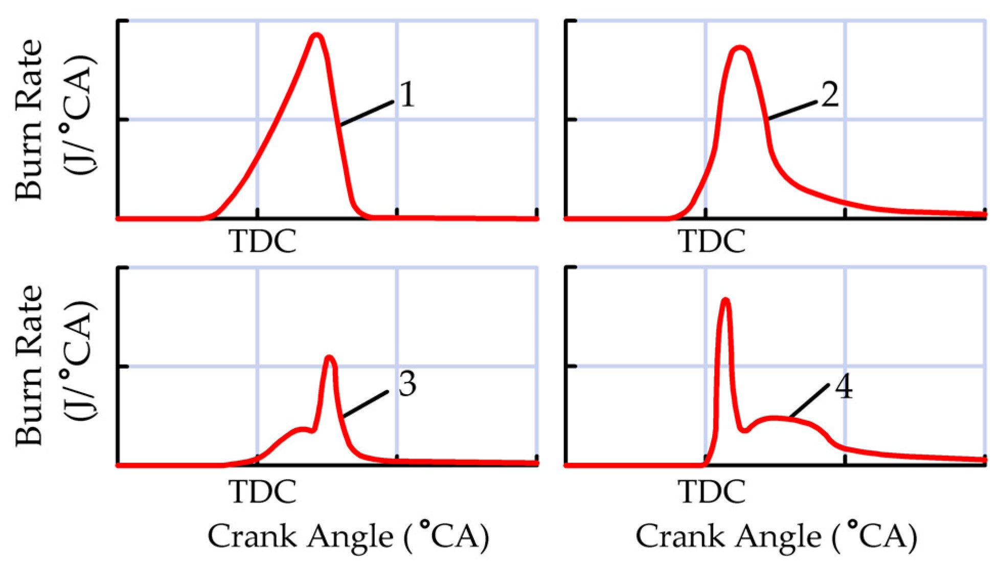
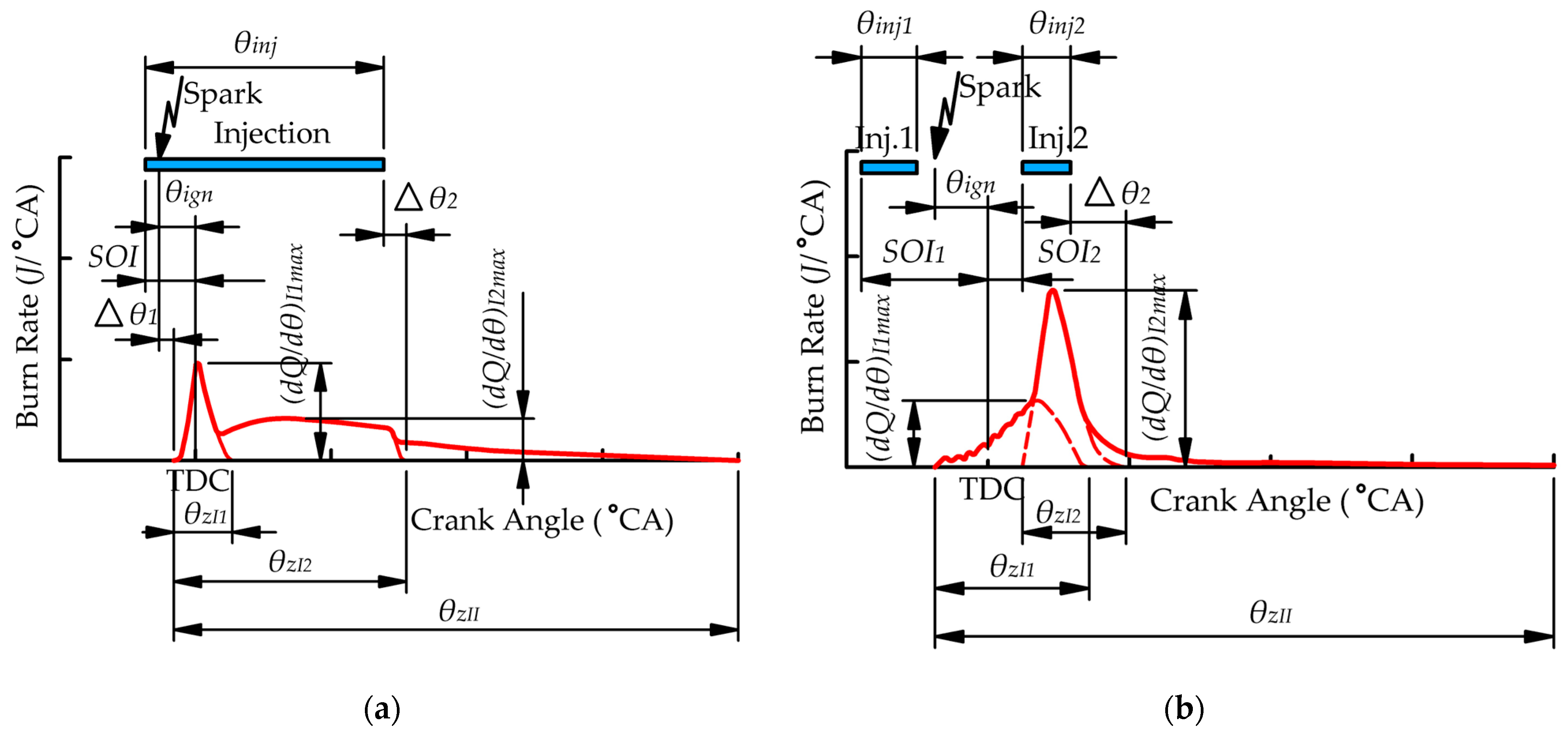
2.3. Evaluation of Combustion Duration from Experimental Data

During the modeling process, the model parameters (primarily the combustion duration) must be validated against experimental data. Estimating the combustion duration from the experimental burn rate curve is a challenging task. Determining the point at which the burn rate reaches zero (i.e., where the burn rate curve intersects the abscissa) is difficult because the curve typically approaches the abscissa asymptotically and often exhibits fluctuations due to the nature of experimental data acquisition and processing. Another reason for the difficulty in quantifying the end of combustion is that the burn rate in the final stage becomes comparable to other ongoing energy transfer processes [40]. Therefore, in practice, the combustion duration is typically measured from 0% to 90% of the burned mixture [41] or from 10% to 90% of the burned mixture [40].
When modeling with Wiebe functions, this method of evaluation is not suitable, as the proposed model requires the determination of the combustion duration for various processes in which different amounts of fuel are burned. Consequently, we adopted the approach described in [8]. In this approach, Wiebe curves are fitted to the heat release rate curve in a way that minimizes the root mean square deviation between the two curves over the majority of the combustion process (Figure 2), while ensuring that the Wiebe curves closely replicate the shape of the heat release rate curve.
It should be noted that this approach to determining combustion duration is somewhat arbitrary, as different types of combustion often occur simultaneously in the cylinder of a hydrogen engine. However, for the purposes of modeling with Wiebe functions, this approach is justified.

2.4. Engines, Operating Modes, and Modeling Features

An analysis of the peculiarities of hydrogen combustion and its modeling was performed for the engines from [3,4,5,7,41]. The main engine parameters are presented in Table 1, and the operating modes for the engines from [3,4,5,7] are shown in Table 2. The engine from [41] was operated over a wide range of speed and load conditions, so its operating modes are not listed in Table 2.
An analysis of the combined effect of engine speed and mixture composition on the hydrogen combustion duration was carried out for a PFI engine based on the research results presented in [41]. The engine parameters are provided in the study on maps covering engine speeds from 800 rpm to 5000 rpm and Brake Mean Effective Pressure (BMEP) values ranging from 0 to 4.2 bar–6.8 bar, depending on the engine speed. The ignition timing (θign) in the experiments was set within a range from 73° CA BITDC to −12° CA BITDC, while the start of injection (SOI) was varied with its end at 180° CA BITDC. The engine operated with a fully open throttle, and the load mode was regulated by altering the mixture composition, with λ varying from approximately 5.5 to 1.43.
Data from [41] were processed to derive the functional dependencies of combustion duration on λ for each selected engine speed. In evaluating the combined influence of mixture composition and engine speed on the combustion duration of hydrogen engines, data from [42,43] were also used. The mathematical analysis of the obtained data made it possible to refine the recommended model coefficients for a broader range of engine speeds (see Section 3.1).
The analysis of the influence of mixture stratification on hydrogen combustion was performed using experimental data for a DI engine from [4]. That study presents hydrogen combustion characteristics for two mixture compositions, λ = 1 and λ = 2.5, and various SOIs, ranging from 300° CA BTDC to 12° CA BTDC (modes 1–8 in Table 2). In all modes, the injection pressure was set at 200 bar and the engine speed at 1500 rpm. Modes 1 and 5 in Table 2 correspond to the combustion of a homogeneous mixture, while modes 2–4 and 6–8 correspond to the combustion of a stratified mixture. In modes 4 and 8, the mixture ignited towards the end of injection, resulting in maximal mixture stratification.
The combustion characteristics presented in [4] allowed for the assessment of the influence of SOI—and, indirectly, mixture stratification—on combustion parameters, which facilitated the appropriate adjustment of the mathematical model (see Section 3.2).
Significant attention in this work is devoted to modeling combustion in a hydrogen engine with single injection and jet-guided operation. This injection strategy is rarely addressed in the literature, and therefore, the experimental data published in [5] provide valuable information.
In that study, the engine speed and IMEP were 1500 rpm and approximately 5 bar, respectively. In all operating modes (modes 9–20 in Table 2), a stoichiometric mixture was used, and the SOI was set at 8° CA BITDC. Injection parameters (injection pressure, injector needle lift) and ignition parameters (ignition timing) were varied. It should be noted that different needle lifts at the same injection pressure resulted in different effective injector nozzle areas and, consequently, different injection durations. In the modeling, the effective injector nozzle area was defined to ensure that the calculated injection durations matched the experimental data. The data presented in [5] allowed for the adjustment of the mathematical combustion model to account for the injection and ignition parameters under jet-guided operation (see Section 3.3).
The influence of dual-injection parameters on hydrogen combustion was studied for a single engine from [3,7] under various compression ratios, engine speeds, and loads (modes 9–11 in Table 2). In these modes, the ratios between the injections, injection pressures, ignition timings, and the start of the first and second injections were varied. This enabled the tuning of the mathematical combustion model to account for a wide range of influencing parameters (see Section 3.4).

3. Results and Discussion

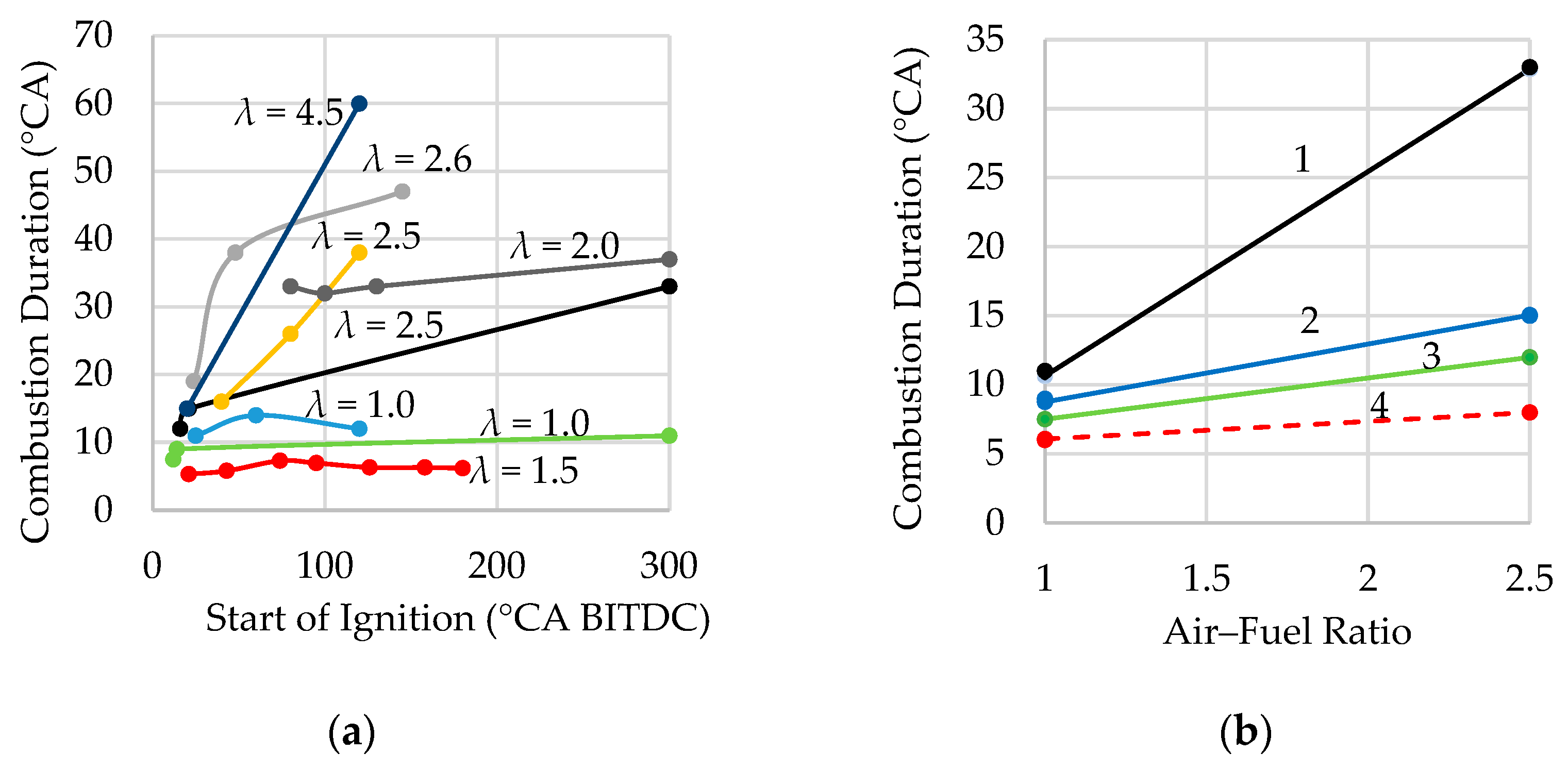
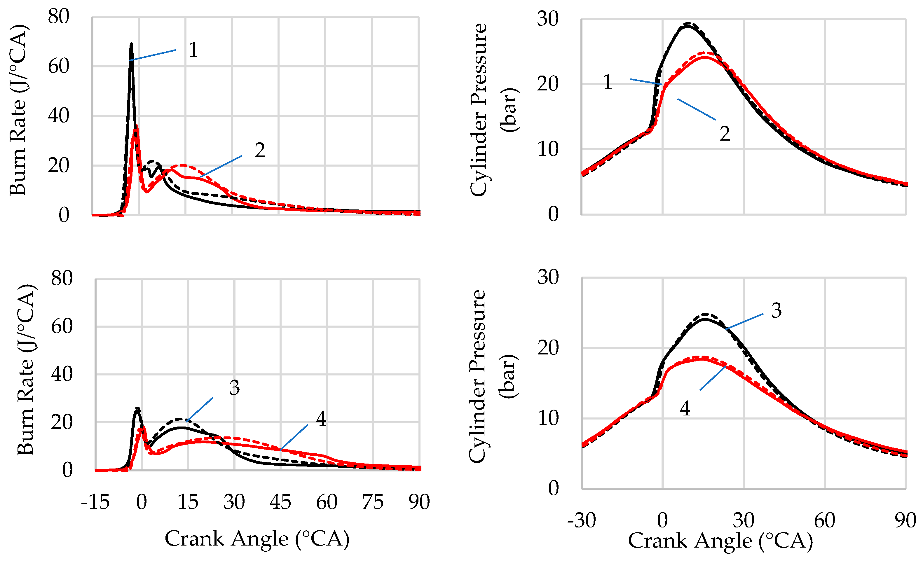
3.1. The Influence of Mixture Composition and Engine Speed on the Hydrogen Combustion

An important parameter in the developed mathematical model is the coefficient k1, which accounts for the influence of the mixture composition on the hydrogen combustion duration at a given engine speed. The higher the value of this coefficient, the greater the influence of λ on the combustion duration relative to that of a stoichiometric mixture.
Figure 3 shows the effect of mixture composition on hydrogen combustion duration in the cylinders of PFI and DI engines, based on data from [3,6,42,44]. The experimental data are represented by points, while the calculated results using Equation (4) for defined values of coefficient k1 are shown as lines. For PFI engines or DI engines with early injection, the coefficient k1 takes higher values (Figure 3a) than for DI engines with relatively late injection (Figure 3b) at the same engine speed. Accordingly, the influence of λ on the combustion duration is higher for homogeneous mixtures than for stratified ones.
From Figure 3, it can be observed that as engine speed increases, the value of the coefficient k1 decreases. For example, for the PFI engine from [42], at a speed of 4000 rpm, the coefficient k1 is 1.1, while for the DI engine with hydrogen injection during the intake stroke (SOI = 300° CA BITDC) from [6], at a speed of 1200 rpm, the coefficient k1 is 1.29. This indicates that as engine speed increases, the influence of the mixture composition on the combustion duration decreases.
Figure 4a shows the effect of engine speed on the value of coefficient k1 for the PFI engine from [41], selected based on the best agreement between experimental and calculated data. It can be seen that this coefficient varies from 1.32 at a speed of 1000 rpm to 0.83 at 5000 rpm. Thus, the influence of λ on combustion duration is significantly higher at low engine speeds than at high ones.
The dependence of coefficient k1 on engine speed for the engine from [41] can be described by a second-degree function of engine speed (Curve 1 in Figure 4):
k 1 = 1.07 × 10 8 · n 2 1.751 × 10 4 · n + 1.469 .
In Figure 4a, the values of the coefficient k1 obtained during the modeling of hydrogen combustion for PFI engines and DI engines with early injection from [3,4,6,28,42] at various speed modes are also plotted. It can be seen that the values of the coefficient k1 for these engines are quite close to Curve 1. Thus, it can be concluded that the relationship between combustion duration, mixture composition, and engine speed for the engine from [41] is quite typical for PFI hydrogen engines and DI engines with early injection. However, this still needs to be complemented with data covering a wider range of engine types.
The coefficient k2 of the model accounts for the influence of engine speed on the duration of stoichiometric mixture combustion. In [38], it is shown that for the engine from [43], good agreement with experimental data is achieved when k2 = 0.39. When calculating the combustion duration for the engine from [41], this coefficient was kept unchanged.
The results of the combustion duration calculation for the engine from [41] are shown in Figure 4b (solid lines). In this case, the engine speed and combustion duration at the nominal mode were set to 5000 rpm and 22° CA, respectively. The coefficient k1 was determined using Formula (5), while the coefficient k2 was taken as a constant value of 0.39. It can be seen that the proposed method provides satisfactory agreement between the experimental and calculated data over a wide range of engine speeds.
In work [41], the combustion duration of the stoichiometric mixture is not specified. However, from Figure 4b, it is evident that the calculated values of this parameter match well with the experimental data for the engine from [43]. Therefore, it can be concluded that the effect of turbulence in the cylinder, caused by changes in engine speed, on the combustion of the stoichiometric mixture is approximately the same for both engines. This allows for a broader generalization of the results obtained for the engines from [41,42].

3.2. The Influence of Mixture Stratification on the Hydrogen Combustion

From Figure 3, it follows that the influence of the air–fuel ratio on combustion duration in DI engines is somewhat lower than in PFI engines. In DI engines, injection often occurs during the compression stroke, and by the time of ignition, the mixture does not have enough time to mix evenly with the air. This leads to the formation of zones with lean and rich mixtures. As a result, combustion in zones with a rich mixture occurs faster than in a homogeneous mixture at the same cylinder-averaged λ. Consequently, the combustion duration in DI engines increases to a lesser extent with growing λ compared to PFI engines.
In our previous study [38], for DI engines, it was recommended to select the coefficient k1, which accounts for the influence of the air–fuel ratio in the range of 0.77 to 1.0. However, the relationship between the degree of mixture stratification and coefficient k1 was not identified. In this research, this relationship was examined in more detail.
One of the main factors influencing the degree of mixture stratification is the start of injection. Figure 5a presents data on the influence of SOI and air–fuel ratio on the combustion duration, as determined from [3,4,6,45,46,47]. An analysis of the data shows that the effect of SOI on combustion duration becomes more pronounced when injection starts at less than 80° CA BTDC, and it becomes particularly significant when SOI occurs at less than 40° CA BTDC. A similar conclusion was arrived at in [47]. Additionally, Figure 5a indicates that the influence of SOI on combustion duration increases as λ rises, especially in cases of late injection.
Of particular interest in this regard are the results of the study presented in [4], which allow for a comparative assessment of the impact of a homogeneous and highly stratified mixture on the hydrogen combustion (Figure 5b) for two mixture compositions with λ = 1.0 and λ = 2.5.
The influence of the mixture composition on the combustion duration of the homogeneous mixture during early injection (curve 1 in Figure 5b) is approximately the same as in PFI engines, with the model coefficient k1 in this case being equal to 1.2.
During the combustion of a highly stratified mixture, the effect of the mixture composition on the combustion duration is significantly smaller. For Curves 2 and 3 in Figure 5b, the coefficient k1 takes the values of 0.59 and 0.51, respectively.
Thus, the obtained data suggest a somewhat wider range for the model coefficient k1 in DI engines, varying from 0.5 to 1.2 at engine speeds of 1500–2000 rpm. In this case, values of k1 closer to the lower boundary of this range should be used for DI engines with late injection (SOIs lower than 80° CA BITDC) and strong mixture stratification. Conversely, values closer to the upper boundary should be applied to DI engines with early injection (during the intake stroke) and a homogeneous mixture.
It should be noted that the degree of mixture stratification is significantly influenced by the fuel injection pressure, the rate of the relative movement of air and fuel in the cylinder, and several other factors. Therefore, the given ranges for k1 can be considered to be approximate. The final value is chosen as a result of tuning the mathematical model to the experimental data.
If we assume that the influence of turbulence, caused by engine speed, on the combustion duration of hydrogen in DI engines is the same as in PFI engines, then with an increase in engine speed, the value of the coefficient k1 should be reduced by the same degree as for PFI engines (see Section 3.1).
The stratification of the mixture leads to an increase in the share of fuel that burns relatively slowly in areas with a lean mixture [30]. When calculating modes with mixture stratification (modes 2, 3, 6, and 7 from Table 2), satisfactory agreement between the experimental and calculated combustion characteristics was achieved by setting the assumed proportion of fuel burning in the lean-mixture zones at approximately 30%. The combustion characteristic exponents for the combustion processes in the flame front and in the lean-mixture zones were selected from the ranges provided in Section 2.2 for DI engines.
The results of hydrogen combustion modeling at different degrees of mixture stratification in the DI engine from [4] for modes 1 and 2 and 5 and 6 from Table 2 are shown in Figure 6. It can be seen that the proposed refinements to the model ensure satisfactory agreement between the experimental and calculated data for various mixture compositions and degrees of air–fuel mixture stratification.

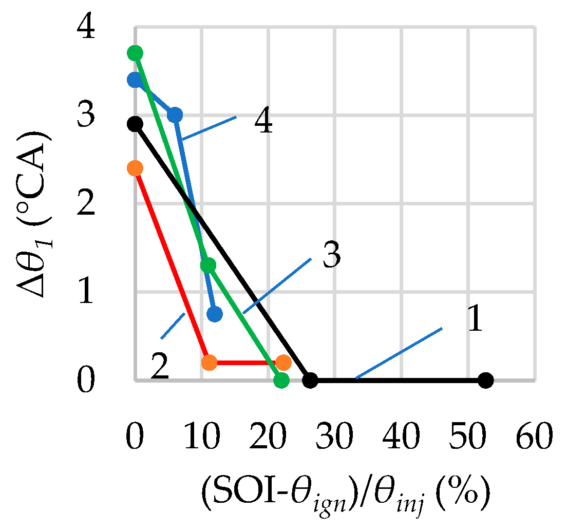
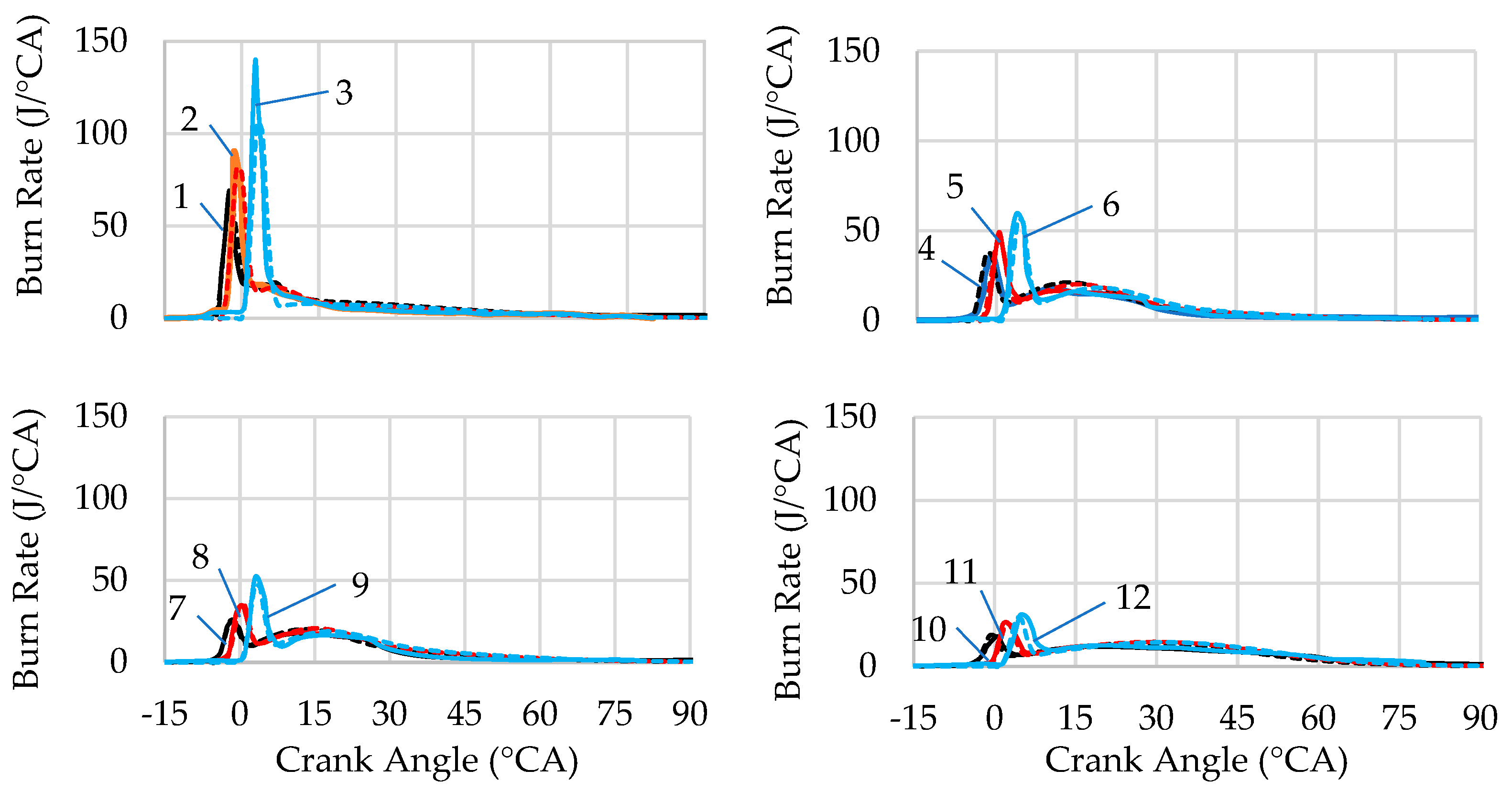
3.3. Influence of Single Injection and Ignition Parameters on Hydrogen Combustion in Jet-Guided Operation

The key parameters of combustion in single injection and jet-guided operation are shown in Figure 7a. The combustion curve typically has two peaks, corresponding to the combustion in the flame front of a highly stratified mixture and diffusion combustion [4,5]. The rate and kinetics of combustion in the flame front are determined by the amount of fuel that has partially mixed with air during the period between the start of injection and ignition [4,5]. Since injection continues after the flame front has formed, new portions of fuel enter the flame front, burning in a diffusion-controlled process. This process is characterized by a slight increase in the combustion rate during the first half of the injection, followed by a slight decrease. After the injection ends, the combustion rate drops to a certain level, followed by a prolonged period of relatively slow combustion. Thus, this combustion process contains the same components as combustion with dual injection (Figure 7b), described in Section 2.2 and Section 2.4.
In the mathematical description of combustion in single injection and jet-guided operation, unlike in the combustion in dual injection, the components of Equation (3) need to be slightly refined and specified. For this process, the function d x d θ I 1 in Equation (3) represents the burn rate in the flame front, while the function d x d θ I 2 represents the diffusion burn rate. The parameters rI1 and rI2 represent the shares of the fuel supply that burn relatively quickly in the flame front and in the diffusion process, respectively. The other model parameters have the same definitions.
The data presented in [4,5] enable us to assess the impact of various factors on the combustion parameters. Analysis of the data shows that the combustion rate and duration in the flame front, represented by d Q d θ I 1 and θzI1, respectively, depend on the injection pressure, the effective injector nozzle area, the air–fuel ratio in the cylinder, and the relative ignition timing:
θ ¯ i g n = S O I θ i g n θ i n j 100 % ,
where SOI is the start of injection, θign is the ignition timing, and θinj is the injection duration.
The influence of the specified factors on the maximum combustion rate and duration in the flame front for the engine from [5] is shown in Figure 8. From Figure 8a, it can be seen that the ignition timing, with the other injection parameters held constant, practically does not affect the combustion duration in the flame front. In this case, θzI1 varies within a narrow range—from 6 to 10° CA—while the total combustion duration in the flame front and diffusion combustion ranges from 20 to 78° CA. The combustion duration in the flame front can be determined using Equation (4) depending on the air–fuel ratio. From Figure 5b, it can be seen that the air–fuel ratio has a slight impact on the duration of this type of combustion (curve 4), which can be explained by the strong mixture stratification. At the same time, a satisfactory agreement with the experimental data is achieved when the k1 coefficient is set to 0.3.
In this type of combustion, there is a significant delay in the onset of active heat release (parameter ∆θ1 in Figure 7) when the ignition timing and SOI coincide (Figure 9). This parameter was determined in this study according to the methodology outlined in Section 2.3 and differs slightly from the parameter “ignition delay”, which is typically defined as the time from ignition to the combustion of 1%, 5%, or 10% of the injected fuel [40]. From Figure 9, it can be seen that the parameter ∆θ1 at ignition, when 10% of the relative injection duration is reached, is approximately 1° CA and then tends toward zero. In the mathematical model, this can be accounted for by a simple linear or quadratic dependence on the relative ignition angle.
The intensity of heat release during the combustion in the flame front can be characterized by the parameter d Q d θ I 1   m a x (see Figure 7a). From Figure 8b, it can be seen that this parameter depends almost linearly on the relative ignition timing and is primarily determined by the amount of fuel burning in the flame front. The fraction of fuel burned in the flame front can be determined from the fuel injection calculation, taking into account the combustion duration in the flame front using the following formula:
r I 1 = S O I θ i g n + θ 1 + θ z I 1 · k I 1 θ i n j ,
where kI1 is a coefficient that accounts for the reduction in the share of fuel burned in the flame front due to the simultaneous occurrence of the diffusion, premixed, and “slow” combustion processes. This coefficient was set in the range from 0.6 to 0.9 during modeling.
Accordingly, the fraction of fuel burned in the diffusion process r I 2 = 1 r I 1 .
During the modeling of combustion in the flame front, the characteristic exponent (mI1) was set in the range from 2.0 to 2.5.
Figure 10 shows the influence of maximum injection pressure, injector needle lift, and injection duration on the duration of diffusion combustion, obtained by processing the data from the work [5]. From Figure 10a, it can be seen that the duration of diffusion combustion decreases with increasing maximum injection pressure and needle lift. Both of these influencing parameters determine the intensity and duration of injection. Figure 10b shows the effect of injection duration at different pressures, ignition timings, and needle lifts on the duration of diffusion combustion (modes 11–20 in Table 2). It is evident that the duration of diffusion combustion is practically proportional to the duration of fuel injection, which confirms the conclusion we previously made in [38].
An analysis of the data from [4,5] shows that the rate of diffusion combustion sharply decreases after the injection ends, at some angle ∆θ2 (see Figure 7). For the engine in [5], when operating at 1500 rpm, the value of ∆θ2 was in the range of 5 to 10° CA, with shorter and more intense injections resulting in a smaller value for this angle. When simulating the operation of this engine, the value of ∆θ2 was assumed to be 7° CA for all modes. Thus, by calculating the duration of hydrogen injection, the duration of diffusion combustion can be relatively easily determined.
As with the duration, the maximum rate of diffusion combustion depends on the intensity of fuel injection. From Figure 11a, it is evident that increasing the injection pressure and injector needle lift leads to a slight increase in the rate of diffusion combustion. However, as shown in Figure 11b, the influence of injection duration on the rate of diffusion combustion is much lower than on the duration of this type of combustion. When the injection duration increases from 8 to 64° CA, the maximum rate of diffusion combustion decreases from approximately 20 J/° CA to 12 J/° CA for modes with various combinations of injection pressure, ignition timing, and injector needle lift (modes 11–20 in Table 2).
The maximum rate of diffusion combustion typically occurs in the first half of the process. Accordingly, when modeling diffusion combustion, the combustion characteristic exponent was set to 1.5–2.0.
An analysis of experimental heat release characteristics and comparison of the calculation results with experimental data shows that a significant share of the fuel burns at a relatively low rate. When modeling for an engine with single injection and J-guided operation, a satisfactory agreement with the experimental data was achieved by setting this portion in the range of 50% to 60% of the cycle’s fuel supply. The combustion characteristic exponent for this type of combustion was set to 0.6.
The results of modeling hydrogen combustion in a DI engine with single injection and jet-guided operation from [5] are shown in Figure 12 and Figure 13. It can be seen that the proposed mathematical model accounts for the influence of injection pressure, effective injector nozzle area, and the relationship between the injection and ignition timings on the hydrogen combustion.

3.4. Influence of Dual Injection and Ignition Parameters on Hydrogen Combustion

Hydrogen combustion with dual injection shares many similarities with combustion with single injection and jet-guided operation, but there are also some differences. The differences primarily lie in the characteristics of the combustion process in the flame front and the mutual influence of premixed and diffusion combustion.
The diagram for determining the combustion parameters for dual injection is shown above in Figure 7b. The first injection in DI engines is often performed during the second half of the compression stroke. By the time the first injection ends, a lean mixture is formed in the cylinder. For example, if the air–fuel ratio, calculated based on the overall cycle fuel supply, is 2 and the fuel share in the first injection is 50%, the averaged air–fuel ratio in the cylinder at the end of the first injection will be 4. However, due to the stratification of the mixture, the burn rate in the flame front after ignition is somewhat higher than during the combustion of a homogeneous mixture at this λ.
As shown in Section 3.2, the influence of λ on the combustion in this case will be less than in DI engines with early injection. For engine operating modes with dual injection (modes 21–23 in Table 2), when the total λ changes from 1 to 2.5, a satisfactory agreement between calculated and experimental data was achieved with a model coefficient k1 ranging from 0.75 to 0.9. When modeling, the start of the active heat release was considered to coincide with the ignition timing, meaning that the angle ∆θ1 (see Figure 7) was assumed to be zero.
In double injection, the model coefficient k2, which accounts for the influence of engine speed on the combustion rate of the stoichiometric mixture, was assumed to be 0.39. The characteristic exponent for the combustion of the mixture in the flame front (mI1) was selected from the range of 2.5 to 2.7.
After the start of the second injection and the onset of diffusion combustion, the average combustion rate in the cylinder generally increases. The maximum combustion rate during this period depends on the difference between the start of the second injection and the ignition timing (SOI2-θign). As this difference decreases, the peaks of the diffusion and premixed combustion rates, occurring simultaneously in the cylinder, approach each other, resulting in a sharp increase in the total combustion rate on the heat release characteristic. The maximum diffusion combustion rate in modes 21–23 in Table 2 was significantly higher than in the case of single injection and jet-guided operation (modes 9–20 in Table 2).
As shown above, the duration and rate of diffusion combustion are primarily determined by the intensity of hydrogen injection into the flame front. An analysis of combustion characteristics in engines with dual injection from [3,7,30,45] shows that the assumed end of diffusion combustion occurs at an angle ∆θ2, which varies between 4° CA and 15° CA. The shorter and more intense the injection, the smaller this difference. In our modeling of dual injection for modes 21–23 in Table 2, the parameter ∆θ2 was chosen from the range 4° CA to 8° CA.
Mixture stratification in engines with double injection can lead to part of the fuel burning in zones with a lean mixture. Calculations show that the greater the share of the second injection (rI2), the higher the assumed share of fuel burning relatively slowly (rII). This statement is confirmed by data from [30], where an increase in the share of the second injection was accompanied by a decrease in the maximum diffusion combustion rate, along with the appearance of a region of slow combustion on the burn rate curve. In the modeling of modes where the ratio of the first to the second injection was 60%/40% and 50%/50%, good agreement with the experimental data was obtained when the rII share was approximately 30%. For the mode with an injection ratio of 45%/55%, the rII share was taken as approximately 40%. The characteristic exponent for “slow” combustion (mII) was set to 1.2.
The results of hydrogen combustion modeling in a DI engine with dual injection from [3,7] for modes 21–23 in Table 2 are shown in Figure 14. It can be seen that the proposed combustion model allows for satisfactory agreement between the experimental and calculated data for various speed and load modes, injection ratios, and air–fuel ratios.

3.5. The Scope of Application of the Developed Combustion Model and Directions for Its Further Development

The developed mathematical model can be used for the approximate evaluation of hydrogen engine performance in the early stages of the design process (conceptual design and simulation). In this case, it is recommended to select the model coefficients from the ranges provided above, depending on the operating parameters and the chosen control strategies. At the design optimization stage, the model can be applied after it has been calibrated for a specific engine and validated against the experimental data.
The main direction for further development of the proposed combustion model is to incorporate a broader range of influencing factors and to refine the model coefficients across a wide variety of hydrogen engine types, operating modes, and conditions. Future work will focus on a detailed investigation of mixture formation and combustion characteristics under dual hydrogen injection and jet-guided combustion strategies.

4. Conclusions

In this work, a mathematical model of hydrogen combustion was modified to account for the combined influence of engine speed and mixture composition, mixture stratification at late injection, fuel injection and ignition characteristics for single injection and jet-guided operation, as well as for dual injection. The following key results were obtained:
  • An approach to determining the duration of premixed and diffusion combustion based on experimental combustion characteristics using the Wiebe function is proposed.
  • It was found that the influence of mixture composition on fuel combustion duration in PFI engines is greater at low engine speeds than at high engine speeds. This influence can be accounted for in the model by selecting the coefficient k1 in Formula (4) from the proposed range or by using the empirical Equation (5).
  • For two different hydrogen engines, the influence of engine speed on the duration of stoichiometric mixture combustion is approximately the same. Accordingly, the model coefficient k2, which accounts for this parameter, does not change significantly between these two engines. This allows for the broader generalization of the obtained results.
  • Significant mixture stratification in DI engines occurs when injection begins later than 80° CA BTDC, and the influence of late SOI on hydrogen combustion duration increases with λ. This effect is accounted for in the combustion model by selecting lower values of the coefficient k1 for late injection from the specified range.
  • Mixture stratification is sometimes accompanied by an increase in the fraction of fuel burning in lean-mixture zones. Model coefficients have been proposed to account for the kinetics of premixed combustion and relatively slow combustion.
  • In single injection and jet-guided operation, strong mixture stratification occurs, and the influence of mixture composition on the combustion duration in the flame front is minimal. A methodology for determining the duration of premixed combustion and the amount of fuel burned in the flame front has been proposed.
  • The duration of diffusion combustion in single injection and jet-guided operation correlates well with the fuel injection duration at various injection pressures, ignition timings, and injector needle lifts. Values or ranges for the model coefficients accounting for the kinetics of different types of combustion at this injection strategy are provided.
  • In dual injection, the duration and rate of premixed combustion are determined by the SOI and the mixture composition in the cylinder at the moment of ignition, while the characteristics of diffusion combustion are mainly influenced by ignition timing and the parameters of the second fuel injection. Values or ranges for the model coefficients that account for the kinetics of different types of combustion at this injection strategy are provided.

Author Contributions

Conceptualization, O.O. and R.H.; methodology, O.O.; software, O.O.; validation, O.O.; formal analysis, O.O. and R.H.; investigation, O.O.; resources, O.O.; data curation, O.O. and R.H.; writing—original draft preparation, O.O. and R.H.; writing—review and editing, O.O. and R.H.; visualization, O.O.; supervision, R.H.; project administration, R.H. All authors have read and agreed to the published version of the manuscript.

Funding

The APC was funded by the Philipp Schwartz Initiative of the Alexander von Humboldt Foundation.

Data Availability Statement

The original contributions presented in the study are included in the article; further inquiries can be directed to the corresponding author.

Acknowledgments

The authors express their gratitude to the leadership of the University of Applied Sciences Cologne and the Faculty of Automotive Systems and Production for providing access to the Matlab software license and facilitating the research and computational aspects of this study.

Conflicts of Interest

The authors declare no potential conflicts of interest with respect to the research, authorship, and/or publication of this article.

Abbreviations

The following abbreviations are used in this manuscript:
BITDCBefore Ignition Top Dead Center
BMEPBrake Mean Effective Pressure
BSFCBrake Specific Fuel Consumption
BTEBrake Thermal Efficiency
CACrank Angle
CFDComputational Fluid Dynamics
DIDirect Injection
ITEIndicated Thermal Efficiency
MFB5050% Mass Fraction Burned
NOxNitrogen Oxides
PFIPort Fuel Injection
SOIStart of Injection

References

  1. Stepien, Z.A. Comprehensive Overview of Hydrogen-Fueled Internal Combustion Engines: Achievements and Future Challenges. Energies 2021, 14, 6504. [Google Scholar] [CrossRef]
  2. Gao, W.; Fu, Z.; Li, Y.; Li, Y.; Zou, J. Progress of Performance, Emission, and Technical Measures of Hydrogen Fuel Internal-Combustion Engines. Energies 2022, 15, 7401. [Google Scholar] [CrossRef]
  3. Gerke, U. Numerical Analysis of Mixture Formation and Combustion in a Hydrogen Direct-Injection Internal Combustion Engine. Ph.D. Thesis, Swiss Federal Institute of Technology, Zürich, Switzerland, 2007. [Google Scholar]
  4. Beyer, A.; Balmelli, M.; Merotto, L.; Wright, Y.M.; Soltic, P.; Kulzer, A. DIH2jet (DI Hydrogen Combustion Process). In 2024 Stuttgart International Symposium on Automotive and Engine Technology; Kulzer, A.C., Reuss, H.C., Eds.; Springer Vieweg: Wiesbaden, Germany, 2024; pp. 53–67. [Google Scholar]
  5. Beyer, A.; Berner, H.J.; Casal Kulzer, A. A Non-premixed Hydrogen Combustion Process Using a Spark-Ignited Hydrogen Jet. In Proceedings of the 2023 Conference on Powertrains with Renewable Energy Carriers, Stuttgart, Germany, 28–29 November 2023. [Google Scholar]
  6. Mohammadi, A.; Shioji, M.; Nakai, Y.; Ishikura, W.; Tabo, E. Performance and Combustion Characteristics of a Direct Injection SI Hydrogen Engine. Int. J. Hydrogen Energy 2007, 32, 296–304. [Google Scholar] [CrossRef]
  7. Spuller, C. Dieselbrennverfahren mit Wasserstoff für PKW-Anwendung. Ph.D. Thesis, Technische Universität Graz, Graz, Austria, 2011. [Google Scholar]
  8. Fouquet, M. Niedrigstemissionskonzept für einen Wasserstoffbetriebenen Verbrennungsmotor. Ph.D. Thesis, Technische Universität München, München, Germany, 2012. [Google Scholar]
  9. Wiebe, I.I. Progress in Engine Cycle Analysis: Combustion Rate and Cycle Processes; Mashgiz: Moscow, Russia, 1962. (In Russian) [Google Scholar]
  10. Ghojel, J.I. Review of the Development and Applications of the Wiebe Function: A Tribute to the Contribution of Ivan Wiebe to Engine Research. Int. J. Engine Res. 2010, 11, 297–312. [Google Scholar] [CrossRef]
  11. Takáts, M.; Macek, J.; Polášek, M.; Kovar, Z.; Beroun, S.; Schloz, C. Hydrogen-Fuelled Reciprocating Engine as an Automotive Prime Mover? In Proceedings of the FISITA World Automotive Congress, Paris, France, 25–30 September 1988.
  12. Ma, J.; Su, Y.; Zhou, Y.; Zhang, Z. Simulation and prediction on the performance of a vehicle’s hydrogen engine. Int. J. Hydrogen Energy 2003, 28, 77–83. [Google Scholar] [CrossRef]
  13. Geiler, J.N.; Springer, K.M.; Lorenz, T.; Blomberg, M.; Achenbach, J.; Bloch, P. H2 Engine Hybrid Powertrain for Future Light Commercial Vehicles. In Internationaler Motorenkongress 2023; Heintzel, A., Ed.; Springer Vieweg: Wiesbaden, Germany, 2024; pp. 53–67. [Google Scholar]
  14. Verhelst, S.; Sierens, R. A Quasi-Dimensional Model for the Power Cycle of a Hydrogen-Fuelled ICE. Int. J. Hydrogen Energy 2007, 32, 3545–3554. [Google Scholar] [CrossRef]
  15. Blizard, N.C.; Keck, J.C. Experimental and Theoretical Investigation of Turbulent Burning Model for Internal Combustion Engines. SAE Int. J. 1974, 740191. [Google Scholar] [CrossRef]
  16. Tabaczynski, R.J.; Ferguson, C.R.; Radhakrishnan, K. A Turbulent Entrainment Model for Spark-Ignition Engine Combustion. SAE Int. J. 1977, 70647. [Google Scholar]
  17. Hires, S.D.; Tabaczynski, R.J.; Novak, J.M. The Prediction of Ignition Delay and Combustion Intervals for a Homogeneous Charge, Spark Ignition Engine. SAE Int. J. 1978, 780232. [Google Scholar]
  18. Tabaczynski, R.J.; Trinker, F.H.; Shannon, B.A.S. Further Refinement and Validation of a Turbulent Flame Propagation Model for Spark-Ignition Engines. Combust. Flame 1980, 39, 111–121. [Google Scholar] [CrossRef]
  19. Millo, F.; Piano, A.; Rolando, L.; Accurso, F.; Gullino, F.; Roggio, S.; Bianco, A.; Pesce, F.; Vassallo, A.; Rossi, R. Synergetic Application of Zero-, One-, and Three-Dimensional Computational Fluid Dynamics Approaches for Hydrogen-Fuelled Spark Ignition Engine Simulation. SAE Int. J. Engines 2022, 15, 561–580. [Google Scholar] [CrossRef]
  20. Rezaei, R.; Hayduk, C.; Sens, M.; Fandakov, A. Hydrogen Combustion—A Puzzle Piece of Future Sustainable Transportation! In Proceedings of the SIA 2020 Digital Powertrain & Energy, Rouen, France, 16–29 November 2020.
  21. D’Errico, G.; Onorati, A.; Ellgas, S. 1D Thermo-Fluid Dynamic Modelling of an S.I. Single-Cylinder H2 Engine with Cryogenic Port Injection. Int. J. Hydrogen Energy 2008, 33, 5829–5841. [Google Scholar] [CrossRef]
  22. Gülder, Ö.L. Turbulent premixed flame propagation models for different combustion regimes. Proc. Combust. Inst. 1990, 23, 743–750. [Google Scholar] [CrossRef]
  23. Lipatnikov, A.N.; Chomiak, J. Turbulent flame speed and thickness: Phenomenology, evaluation, and application in multi-dimensional simulations. Prog. Energy Combust. Sci. 2002, 28, 1–74. [Google Scholar] [CrossRef]
  24. Zimont, V.L. Gas premixed combustion at high turbulence. Turbulent flame closure combustion model. Exp. Therm. Fluid Sci. 2000, 21, 179–186. [Google Scholar] [CrossRef]
  25. Peters, N. Turbulent Combustion; Cambridge University Press: Cambridge, UK, 2000. [Google Scholar]
  26. Changwei, J.; Jinxin, Y.; Xiaolong, L.; Bo, Z.; Shuofeng, W.; Binbin, G. A quasi-dimensional model for combustion performance prediction of an SI hydrogen-enriched methanol engine. Int. J. Hydrogen Energy 2016, 41, 17676–17686. [Google Scholar]
  27. Ma, F.; Deng, J.; Qi, Z.; Li, S.; Chen, R.; Yang, H.; Zhao, S. Study on the calibration coefficients of a quasi-dimensional model for HCNG engine. Int. J. Hydrogen Energy 2011, 36, 9278–9285. [Google Scholar] [CrossRef]
  28. Schmelcher, R.; Kulzer, A.; Gal, T.; Vacca, A.; Chiodi, M. Numerical Investigation of Injection and Mixture Formation in Hydrogen Combustion Engines by Means of Different 3D-CFD Simulation Approaches; SAE Technical Paper 2024-01-3007; SAE International: Warrendale, PA, USA, 2024. [Google Scholar] [CrossRef]
  29. Li, J.; Gao, W.; Zhang, P.; Ye, Y.; Wei, Z. Effects study of injection strategies on hydrogen-air formation and performance of hydrogen direct injection internal combustion engine. Int. J. Hydrogen Energy 2019, 44, 26000–26011. [Google Scholar] [CrossRef]
  30. Wallner, T.; Scarcelli, R.; Nande, A.; Naber, J. Assessment of multiple injection strategies in a direct injection hydrogen research engine. SAE Int. J. Engines 2009, 2, 1701–1709. [Google Scholar] [CrossRef]
  31. Verhelst, S.; Wallner, T. Hydrogen-fueled internal combustion engines. Prog. Energy Combust. Sci. 2009, 35, 490–527. [Google Scholar] [CrossRef]
  32. Convergent Science. CONVERGE Manual, v3.0; Convergent Science: Madison, WI, USA, 2020. [Google Scholar]
  33. Givler, S.; Raju, M.; Pomraning, E.; Senecal, P.; Salman, N.; Reese, R. Gasoline Combustion Modeling of Direct and Port-Fuel Injected Engines Using a Reduced Chemical Mechanism; SAE Technical Paper 2013-01-1098; SAE International: Warrendale, PA, USA, 2013. [Google Scholar]
  34. Broatch, A.; Margot, X.; Novella, R.; Gomez-Soriano, J. Combustion noise analysis of partially premixed combustion concept using gasoline fuel in a 2-stroke engine. Energy 2016, 107, 612–624. [Google Scholar] [CrossRef]
  35. Chiodi, M.; Tortorella, C.; Haro, E.H.; Pipolo, M.; Reuss, H.; Wagner, A. Advancing internal combustion engines and fuel innovation: A modular approach to 3D virtual prototyping for a carbon-neutral future. In 2024 Stuttgart International Symposium on Automotive and Engine Technology; Kulzer, A.C., Reuss, H.C., Eds.; Springer Vieweg: Wiesbaden, Germany, 2024; pp. 85–101. [Google Scholar]
  36. Srivastava, D.K.; Agarwal, A.K.; Datta, A.; Maurya, R.K. Advances in Internal Combustion Engine Research; Springer: Singapore, 2018. [Google Scholar]
  37. Pathak, B.; Shekh, A.; Patel, N.; Patel, V. Review analysis on CFD techniques and numerical methods for IC engines fueled with diesel and biofuels. J. Adv. Res. Fluid Mech. Therm. Sci. 2023, 110, 40–62. [Google Scholar] [CrossRef]
  38. Osetrov, O.; Haas, R. Simulation of Hydrogen Combustion in Spark Ignition Engines Using a Modified Wiebe Model; SAE Technical Paper 2024-01-3016; SAE International: Warrendale, PA, USA, 2024. [Google Scholar]
  39. Dyachenko, V.G. Theory of Internal Combustion Engines: Textbook; KhNADU: Kharkiv, Ukraine, 2009. (In Russian) [Google Scholar]
  40. Heywood, J.B. Internal Combustion Engine Fundamentals; McGraw-Hill: Singapore, 1988. [Google Scholar]
  41. Tang, X.; Kabat, D.M.; Natkin, R.J.; Stockhausen, W.F. Ford P2000 Hydrogen Engine Dynamometer Development; SAE Technical Paper 2002-01-0242; SAE International: Warrendale, PA, USA, 2002. [Google Scholar]
  42. Bai-gang, S.; Hua-yu, T.; Fu-shui, L. The distinctive characteristics of combustion duration in hydrogen internal combustion engine. Int. J. Hydrogen Energy 2014, 39, 14472–14478. [Google Scholar] [CrossRef]
  43. Grabner, P.; Eichlseder, H.; Gerbig, F.; Gerke, U. Optimisation of a hydrogen internal combustion engine with inner mixture formation. In Proceedings of the 1st International Symposium on Hydrogen Internal Combustion Engines, Graz, Austria, 28–29 September 2006. [Google Scholar]
  44. Tsujimura, T.; Suzuki, Y. Development of a large-sized direct injection hydrogen engine for a stationary power generator. Int. J. Hydrogen Energy 2019, 44, 11355–11369. [Google Scholar] [CrossRef]
  45. Tanno, S.; Ito, Y.; Michikawauchi, R.; Nakamura, M.; Tomita, H. High-efficiency and low-NOx hydrogen combustion by high pressure direct injection. SAE Int. J. Engines 2010, 3, 259–268. [Google Scholar] [CrossRef]
  46. Eichlseder, H.; Wallner, T.; Gerbig, F.; Fickel, H. Gemischbildungs- und Verbrennungskonzepte für den Wasserstoff-Verbrennungsmotor. In Proceedings of the 7th Symposium ‘Entwicklungstendenzen bei Ottomotoren’, Technische Akademie Esslingen, Ostfildern, Germany, 12–13 December 2004. [Google Scholar]
  47. Huang, Z.; Wang, L.; Pan, H.; Li, J.; Wang, T.; Wang, L. Experimental study on the impact of hydrogen injection strategy on combustion performance in internal combustion engines. ACS Omega 2023, 8, 39427–39436. [Google Scholar] [CrossRef]
Figure 1. Examples of combustion characteristics in hydrogen engines: 1—in PFI engines or DI engines with early injection; 2—in DI engines with late injection; 3—in DI engines with dual injection; 4—in DI engines with single late injection and jet-guided operation.
Energies 18 03004 g001
Figure 2. Determining the combustion duration in the flame front (θzI1) and the diffusion combustion duration (θzI2) in an engine with dual injection.
Energies 18 03004 g002
Figure 3. The influence of mixture composition on hydrogen combustion duration: (a) PFI engines from [3,42] (curves 1 and 2, respectively) and a DI engine with SOI = 300° CA BITDC from [6] (curve 3); (b) DI engines with SOIs from 80° CA BITDC to 120° CA BITDC from [3,6,44] (curves 4, 5, and 6, respectively). The markers indicate experimental data, while the lines represent calculation results using Formula (4).
Energies 18 03004 g003
Figure 4. The selection of the coefficient k1 in Formula (4) (a) and the results of combustion duration calculations (b) for the PFI engine from [41] (red points and lines). Data for hydrogen PFI engines and DI engines with early injection from [3,4,6,28,42,43] are also presented (black crosses). The markers indicate experimental data, while the lines show the calculation results using Formulas (4) and (5).
Energies 18 03004 g004
Figure 5. The influence of the start of injection (a) and air–fuel ratio (b) on the combustion duration in the flame front in DI hydrogen engines based on the data from [3,4,6,45,46,47] (a) and [4] (b): 1—SOI = 300° CA BITDC, modes 1 and 5 from Table 2; 2—SOI = 14° CA BITDC and 21° CA BITDC, respectively, modes 2 and 6 from Table 2; 3—SOI = 12° CA BITDC and 16° CA BITDC, respectively, modes 3 and 7 from Table 2; 4—SOI = 9° CA BITDC and 21° CA BITDC, respectively, modes 4 and 8 from Table 2. The dashed line shows the combustion duration in the flame front for jet-guided operation (curve 4).
Energies 18 03004 g005
Figure 6. The influence of mixture stratification on the combustion in the DI hydrogen engine from [4]: 1—homogeneous mixture (Mode 1 in Table 2); 2—stratified mixture (Mode 2 in Table 2); 3—homogeneous mixture (Mode 5 in Table 2); 4—stratified mixture (Mode 6 in Table 2). The solid lines represent the experimental data, adapted from [4], while the dashed lines represent the simulation results.
Energies 18 03004 g006aEnergies 18 03004 g006b
Figure 7. Key parameters of combustion in single injection and jet-guided operation (a) and in dual injection (b).
Energies 18 03004 g007
Figure 8. The influence of injection parameters on the combustion duration (a) and on the maximum burn rate (b) in the flame front obtained by processing data from [5]: 1—pinj = 190 bar and “high” needle lift (modes 12–14 in Table 2); 2—pinj = 80 bar and “high” needle lift (modes 18–20 in Table 2); 3—pinj = 190 bar and “low” needle lift (modes 9–11 in Table 2); 4—pinj = 80 bar and “low” needle lift (modes 15–17 in Table 2).
Energies 18 03004 g008
Figure 9. The influence of injection pressure, needle lift, and relative ignition timing on the delay in the onset of active heat release in a DI engine, obtained by processing data from [5]: 1—pinj = 190 bar, “high” needle lift (modes 12–14 in Table 2); 2—pinj = 80 bar, “high” needle lift (modes 18–20 in Table 2); 3—pinj = 190 bar, “low” needle lift (modes 9–11 in Table 2); 4—pinj = 80 bar, “low” needle lift (modes 15–17 in Table 2).
Energies 18 03004 g009
Figure 10. The influence of injection pressure and injector needle lift (a), as well as injection duration (b), on the duration of diffusion combustion, obtained by processing the data from the work [5]: 1—“low” needle lift (modes 9 and 15, Table 2); 2—“high” needle lift (modes 12 and 18 in Table 2). The points in (b) show the duration of diffusion combustion for modes 9–20.
Energies 18 03004 g010
Figure 11. The influence of maximum injection pressure and injector needle lift (a), as well as injection duration (b), on the maximum rate of diffusion combustion in a DI engine, obtained from the data analysis in [5]: 1—“low” needle lift (modes 12 and 18 in Table 2); 2—“high” needle lift (modes 15 and 21 in Table 2). The points in (b) show the maximum rate of diffusion combustion for modes 9–20.
Energies 18 03004 g011
Figure 12. The influence of injection pressure and injector needle lift on hydrogen combustion with jet-guided operation in a DI engine from [5]: 1—pinj = 190 bar and “high” needle lift (mode 12 in Table 2); 2—pinj = 190 bar and “low” needle lift (mode 9 in Table 2); 3—pinj = 80 bar and “high” needle lift (mode 19 in Table 2); 4—pinj = 80 bar and “low” needle lift (mode 15 in Table 2). The solid lines represent the experimental data, adapted from [5], while the dashed lines represent the modeling results.
Energies 18 03004 g012
Figure 13. The influence of the ignition timing on hydrogen combustion with jet-guided operation in a DI engine from [5]: 1, 2, and 3—corresponding to modes 12, 13, and 14 in Table 2, respectively; 4, 5, and 6—corresponding to modes 9, 10, and 11 in Table 2, respectively; 7, 8, and 9—corresponding to modes 18, 19, and 20 in Table 2, respectively; 10, 11, and 12—corresponding to modes 15, 16, and 17 in Table 2, respectively. The solid lines represent the experimental data, adapted from [4], and the dashed lines represent the simulation results.
Energies 18 03004 g013
Figure 14. The results of combustion modeling for engines with dual injection: 1—the engine from [7], mode 21 in Table 2; 2—the engine from [7], mode 22 in Table 2; 3—the engine from [3], mode 23 in Table 2. The solid line represents the experimental data, adapted from [3,7], and the dashed line represents the modeling results.
Energies 18 03004 g014
Table 1. Parameters of the engines from [3,4,5,7,41].
ParameterValue [41]Value [4,5]Value [3]Value [7]
Number of Cylinders4111
Bore (mm)84838484
Stroke (mm)8892.49090
Compression Ratio12.5101017.5
Valve Number16444
Hydrogen Injection MethodPFIDIDIDI
Table 2. The modes of the engines from [3,4,5,7].
ModeSourceIMEP
(bar)
Speed (rpm)Air–Fuel RatioSpark Timing
(° CA BITDC)
SOI1
(° CA BITDC)
SOI2
(° CA BITDC)
Fuel Mass Share: First Injection/Second Injection (%/%)Injection Pressure (bar)Injector Needle Lift
1[4]515001−1300-100/0200-
2[4]515001−114-100/0200-
3[4]515001−112-100/0200-
4[4]515001912-100/0200-
5[4]1015002.58300-100/0200-
6[4]1015002.5−121-100/0200-
7[4]1015002.5−316-100/0200-
8[4]1015002.5812-100/0200-
9[5]4.841500188-100/0190low
10[5]4.841500148-100/0190low
11[5]4.841500108-100/0190low
12[5]4.981500188-100/0190high
13[5]4.981500148-100/0190high
14[5]4.981500108-100/0190high
15[5]5.181500188-100/080low
16[5]5.181500148-100/080low
17[5]5.181500108-100/080low
18[5]4.71500188-100/080high
19[5]4.71500148-100/080high
20[5]4.71500108-100/080high
21[7]6.320002.51127−860/40200-
22[7]7.1110021027−1050/50200-
23[3]102000113120545/55150-
Disclaimer/Publisher’s Note: The statements, opinions and data contained in all publications are solely those of the individual author(s) and contributor(s) and not of MDPI and/or the editor(s). MDPI and/or the editor(s) disclaim responsibility for any injury to people or property resulting from any ideas, methods, instructions or products referred to in the content.

