Article

Dynamic Load Management in Modern Grid Systems Using an Intelligent SDN-Based Framework

by
Khawaja Tahir Mehmood
1 and
Muhammad Majid Hussain
2,*
1
Department of Electrical Engineering, Bahauddin Zakariya University, Multan 60000, Pakistan
2
School of Engineering and Physical Sciences, Heriot-Watt University, Edinburgh EH14 4AS, UK
*
Author to whom correspondence should be addressed.
Energies 2025, 18(12), 3001; https://doi.org/10.3390/en18123001
Submission received: 7 May 2025 / Revised: 31 May 2025 / Accepted: 3 June 2025 / Published: 6 June 2025

Abstract

:
For modern power plants to be dependable, safe, sustainable, and provide the highest operational efficiency (i.e., enhance dynamic load distribution with a faster response time at reduced reactive losses), there must be an intelligent dynamic load management system based on modern computational techniques to prevent overloading of power devices (i.e., alternators, transformers, etc.) in grid systems. In this paper, a co-simulation framework (Panda-SDN Load Balancer) is designed to achieve maximum operational efficiency from the power grid with the prime objective of real-time intelligent load balancing of operational power devices (i.e., power transformers, etc.). This framework is based on the integration of two tools: (a) PandaPower (an open-source Python tool) used for real-time power data (voltage; current; real power, PReal; apparent power, PApparent; reactive power, PReactive; power factor, PF; etc.) load flow analysis; (b) Mininet used for the designing of a Software-Defined Network (SDN) with a POX controller for managing the load patterns on power transformers after load flow analysis obtained through PandaPower via the synchronization tool Message Queuing Telemetry Transport (MQTT) and Intelligent Electrical Devices (IEDs). In this research article, the simulation is performed in three scenarios: (a) normal flow, (b) loaded flow without the proposed framework, and (c) loaded flow with the proposed framework. As per simulation results, the proposed framework offered intelligent substation automation with (a) balanced utilization of a transformer, (b) enhanced system power factor in extreme load conditions, and (c) significant gain in system operational efficiency as compared to legacy load management methods.

1. Introduction

With the rapid growth of industrialization, urbanization, and the incorporation of renewable energy sources, there is an ever-growing need for intelligent power load management systems [1], which are functional in power grids and provide a highly efficient uninterrupted power supply. The power transformer is an essential part of both power generation and distribution systems [2]. Uneven load distribution among transformers, however, can result in major problems with efficiency and dependability, such as overheating, higher operating losses, and a shorter lifespan [3]. This section is further subdivided into five subsections, which are presented below.

1.1. Background and Motivation

Transformers are the key components in the power system for the distribution of electric power to consumers, with the responsibilities of stepping up and stepping down the system voltage (depending upon the generation, transmission, and distribution phase of the power cycle). However, the transformers are often subjected to variable and fluctuating load conditions that can lead to overloading, system failure, and other losses [4]. Overloading occurs when the transformer is operated above its rated capacity. If this phenomenon happens, the following effects occur: (a) excessive heat generation, (b) voltage drop, (c) more current is drawn, (d) accelerated ageing of the transformer, (d) power transformer failure, and (e) collapse of the whole interconnected system [5]. The power losses occurring during overloading are mathematically given in Equation (1):
P L _ t o t a l = P L _ c u + P L _ c o r e
In Equation (1) the total power losses (PLtotal) depend upon copper losses (PLcu) and core losses (PLcore). PLcore losses normally remain stable under different load conditions but increase due to overloading due to higher magnetic saturation. PLcu is directly proportional to the square of current (I2R). When the power transformer is overloaded, the current drawn from the system increases, and PLcu increases, resulting in enhanced heat generation and electrical losses. Due to this overloading, the overall system power factor (PF) is also degraded with greater demand for apparent power (PApparent), and the grid is required to supply more reactive power (PReactive) [6]. The mathematical form of these parameters is shown in Equations (2)–(4).
P R e a l = V I cos ( θ )
P A p p a r e n t = V I
P F = V I cos ( θ ) V I
Regarding Equations (1)–(4), effective load management in power transformers is essential to maintain the reliability and efficiency of the power system [7]. In this research paper, the proposed framework is implemented to obtain maximum operational efficiency (i.e., enhance dynamic load distribution with a faster response time at reduced reactive losses, etc.) from the power system with real-time dynamic load management of power transformers.

1.2. Need for Intelligent Dynamic Load Management

The intelligent dynamic load management system can automatically detect the overloading condition in the power transformers and redistribute its load among under-utilized transformers to optimize transformer usage and efficiency of the power grid system [8]. The Software-Defined Network (SDN), with separate data and control planes, can create a flexible and programmable control layer in the power grid [9]. The system administrator uses a Python-coded program in the form of Application Programmable Instruction (API) via Northbound to instruct the controller of the SDN (POX in our model) to automatically manage the power transformer load, preventing overloading and degradation in power system performance [10]. The working model of the SDN is shown in Figure 1.
The SDN controller can continuously monitor the data logs of the system components that are meant to be controlled and compare the data sets obtained from the monitoring task using a defined threshold; if there are any variations from the threshold level, a control signal is immediately generated to nullify the variations from the threshold level without disturbing the operation of the other components of the system [11]. Due to this dynamic feature, the SDN (POX) controller is used to monitor the data sets (load profile) of each transformer and distribute the load on each transformer based on a user-defined threshold level.

1.3. Work Contribution

This paper proposes a co-simulation framework (Panda-SDN Load Balancer) to achieve maximum operational efficiency (i.e., enhance dynamic load distribution with a faster response time at reduced reactive losses, etc.) from the power grid with the prime objective of real-time intelligent load balancing of operational power devices (i.e., power transformers, etc.). This framework is based on the integration of two tools: (a) PandaPower (an open-source Python Tool) used for real-time power data (voltage, current, rated power, apparent power, reactive power, power factor, etc.) load flow analysis. The data of load flow analysis is gathered using Intelligent Electronic Devices (IEDs). The data obtained from IEDs is sent to a communication broker, namely Message Queuing Telemetry Transport (MQTT), for further processing of data. (b) Mininet for the designing of a Software-Defined Network (SDN) with a POX controller for managing the load patterns on power transformers using an artificial-intelligence-based load-balancing algorithm (AILB) after load flow analysis obtained through PandaPower via the synchronization tool Message Queuing Telemetry Transport (MQTT). The working model is shown in Figure 2.

Features and Advantages of the Proposed Method

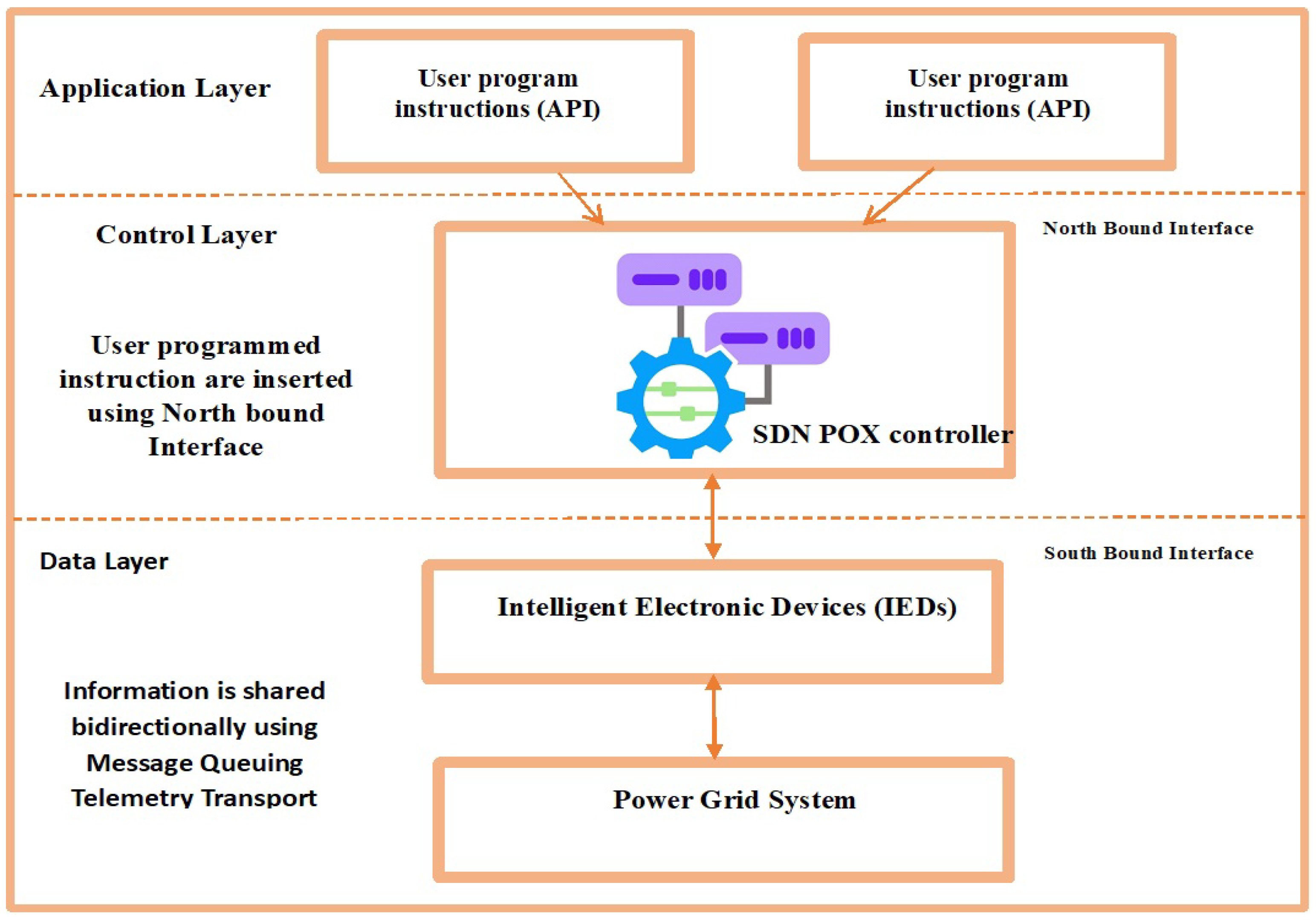
  • The Union of Heterogeneous Domain Models as a Co-Simulation Environment: The power system analysis, conducted using PandaPower, and network control, using Mininet via the POX SDN controller, have been maintained separately until now. With our approach, a unified framework is created enabling real-time control of power network systems involving the exchange of control information between two different domains more quickly and effectively.
  • Compatibility via MQTT: MQTT is a lightweight protocol used as a messaging interface between two heterogeneous domains. In the proposed technique, the MQTT enables Intelligent Electronic Devices (IEDs) to deliver their transformer load data to the SDN controller in real time. It means this framework with MQTT can handle changes in decisions without pausing any simulations.
  • Customized and Modular Approach: In our proposed method, the user-defined topology, transformer thresholds, and SDN logic are modular, and they can be modified quickly for use on different networks.
  • Application of an AI Load Balancer (AILB) for Control Techniques: The proposed framework uses an SDN controller with a load balancer in the form of AI-powered algorithms that replace static control logic with adaptive responses to achieve maximum efficiency in terms of high power factor and decrease in overloading of power transformers.
  • Dynamic Load Optimization Mechanism: With the real-time determination of overloaded (>90%) and under-utilized (<40%) transformers and redistributing the load to maintain all transformers under 70%, the reliability of the system increases, with avoidance of overloading and reduction in energy loss.

1.4. Research Objectives

  • To monitor real-time transformer load data.
  • To enable the SDN (POX) controller to redistribute load and prevent overloading phenomena.
  • To improve system operational efficiency (i.e., enhance dynamic load distribution with faster response time at reduced reactive losses, etc.), reduce transformer overloading, maintain high power factor, and minimize losses.

1.5. Paper Arrangement

In Section 2, the literature review is discussed along with a comparison of the proposed technique with already-existing load management techniques. In Section 3, the methodology is discussed in the form of steps to obtain the desired objective. In the last section, the simulation results are discussed along with a conclusion.

2. Literature Review

To make the power grid highly reliable, efficient, and sustainable, the management of the transformer load is very essential. Overloading in the transformers can cause excessive heat generation, voltage drop, more current drawn, accelerated ageing of the transformer, power transformer failure, and collapse of a whole interconnected system. The authors over the years have proposed different techniques to combat this issue. Table 1 explains the contributions and limitations of techniques used by different authors to enhance the efficiency of the power grid.

3. Research Methodology

To make the power grid system highly efficient and prevent the transformer from overloading, the proposed framework is implemented. This section includes details about the complete working of the proposed framework, mathematical modelling, and simulation parameters.

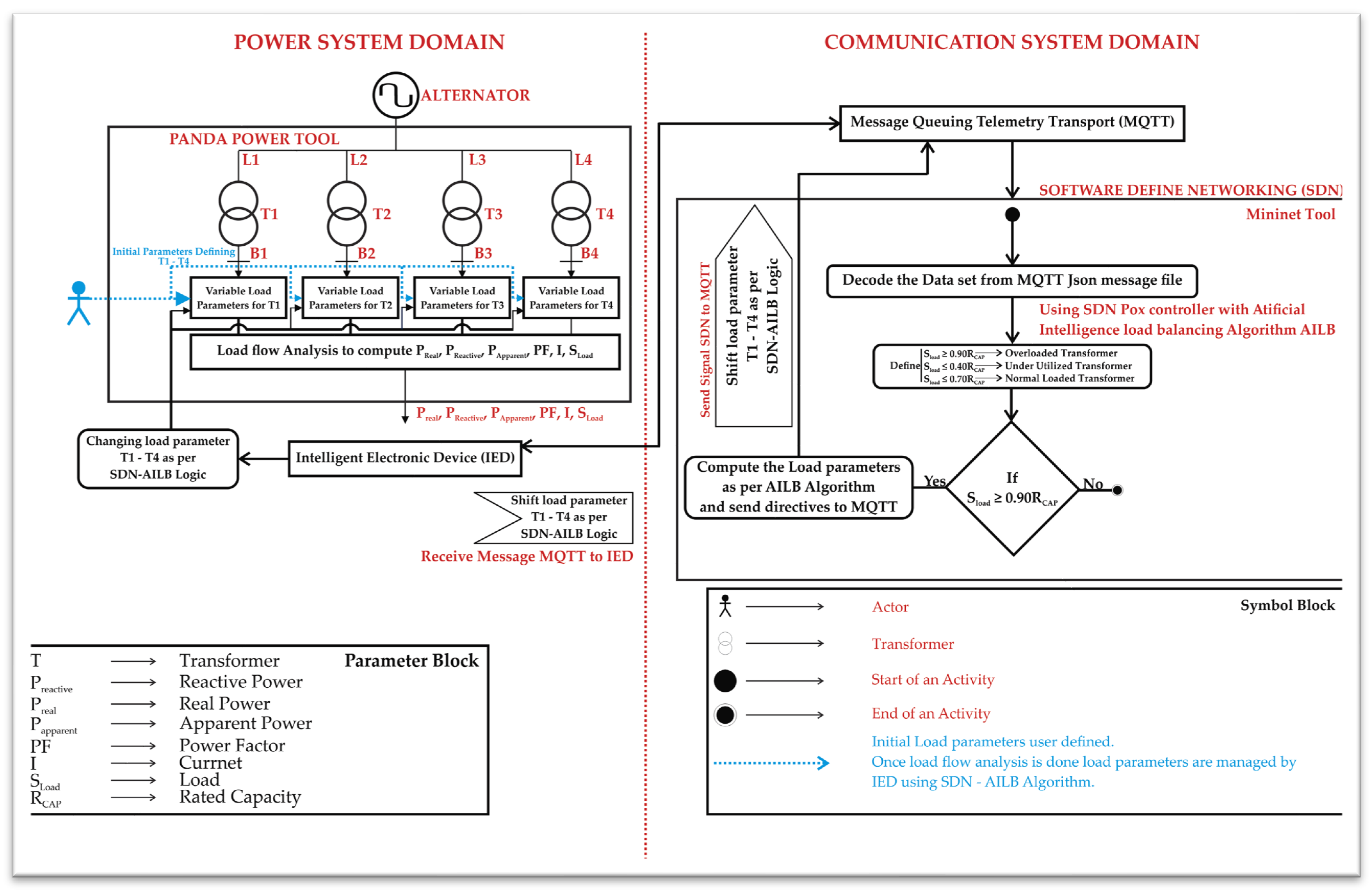
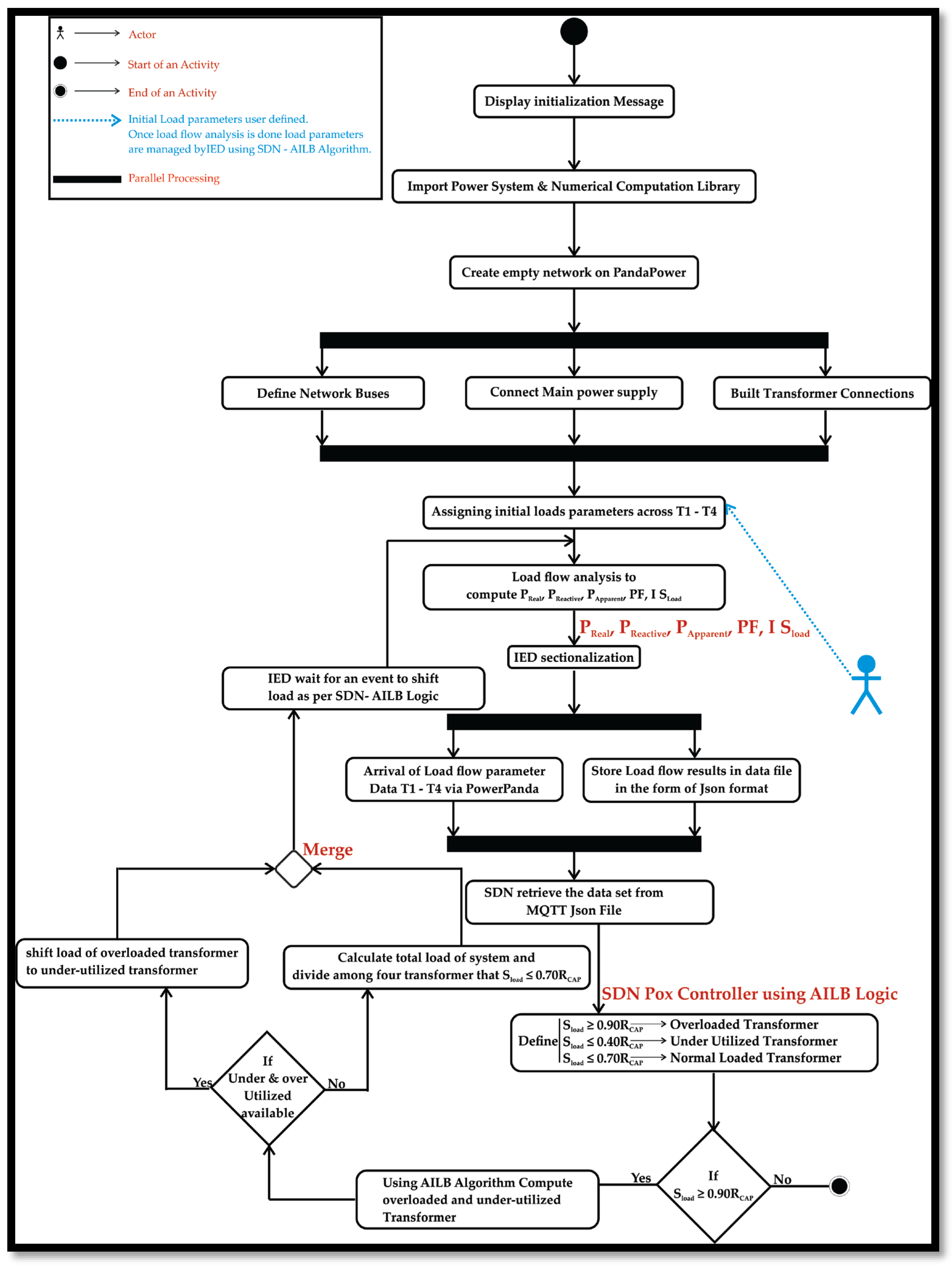
3.1. Working on the Proposed Framework

  • Step 1:
First, the user-defined power system topology is designed on PandaPower. The selected topology consists of an alternator (Rcapacity = 50 MVA, Rvoltage = 11 kv) supplying a busbar connected with four transformers (T1, T2, T3, and T4). The rated capacity of these transformers is 1.0 MVA. In our co-simulation model, when the load (SLoad) of any transformer (T1, T2, T3, or T4) is ≥0.90 Rcapacity, it is considered overloaded, and when the Sload of any transformer (T1, T2, T3, or T4) is ≤0.40 Rcapacity, it is considered under-utilized. To combat overloading and under-utilization issues, the SDN controller is fed with an AI-based script to redistribute the load among all the operating transformers (this solution is explained in detail in Step 3). PandaPower is a Python-based tool that is used to perform the following key analysis on the user-defined system topology:
(a)
Power Flow Analysis: Calculation of bus voltage, branch loading, power loss, active power, reactive power and power factor of each transformer, and overall system power factor.
(b)
Transformer Loading: Analysis of overloading (SLoad ≥ 0.90 Rcapacity) and under-utilization (SLoad ≤ 0.40 Rcapacity) scenarios among all transformers.
(c)
Load Distribution: Simulation of the scenarios to test where the load is redistributed or how the load characteristics are modified through IEDs under SDN controller influence.
Algorithm 1 represents the set of commands used for the creation of user-defined topology and to perform load flow analysis.
Algorithm 1: Designing Power Network Topology on PanadaPower and Performing Load Flow Analysis
1.  
BEGIN
# Initialize Libraries for Power System Modeling
IMPORT power system simulation library (pp)
IMPORT numerical computation library (np)
2.  
#Set Up Electrical Network Model
net ← create empty network ()
3.  
# Define Network Buses (Nodes)
bus_slack ← create_bus(net, voltage_kV = 11, name = “Slack Bus”)
bus_T1 ← create_bus(net, voltage_kV = 11, name = “Bus T1”)
bus_T2 ← create_bus(net, voltage_kV = 11, name = “Bus T2”)
bus_T3 ← create_bus (net, voltage_kV = 11, name = “Bus T3”)
bus_T4 ← create_bus (net, voltage_kV = 11, name = “Bus T4”)
4.  
#Connect Main Power Source (Alternator)
create_ext_grid (net, bus = bus_slack, voltage_pu = 1.0, name = “Alternator (50 MVA)”)
5.  
#Build Transformer Connections Using Line Segments
FOR each transformer_bus IN [bus_T1, bus_T2, bus_T3, bus_T4]
DO
create_line (net, from_bus = bus_slack, to_bus = transformer_bus, length_km = 0.1, resistance = 0.4 ohm/km, reactance = 0.2 ohm/km, capacitance = 0 nF/km, max_current = 1.0 kA)
END FOR
6.  
# Specify Transformer Capacity Limits
T1_rated_mva ← 1.0
T2_rated_mva ← 1.0
T3_rated_mva ← 1.0
T4_rated_mva ← 1.0
7.  
# Get User Input for Initial Load (P in kW, PF assumed)
voltage_LL ← 400              # line-to-line voltage (V)
PF_default ← 0.95
FOR each Ti IN [T1, T2, T3, T4]
PReal_Ti_kW ← USER_INPUT (“Enter load for transformer “ + Ti + “ (kW)”)
PReactive_Ti_kVAR ← P_Ti_kW × tan (arc cos (PF_default))
ADD load at bus_Ti: PReal _mw = PReal Ti_kW/1000, PReactive _mvar = PReactive _Ti_kVAR/1000
END FOR
8.  
# Execute Load Flow Analysis
run_power_flow(net)
9.  
# Compute and Report Apparent Load for Each Transformer
FOR each load IN net. Load
bus ← get_bus_for_load(load)
PReal ← get_real_power(load)
PReactive ← get_reactive_power(load)
SLoad = PApparent ← sqrt (PReal2 + PReactive2)
I ← (S × 10⁶)/(sqrt (3) × voltage_LL)
PF ← PReal/PApparent
PRINT “Transformer”, Ti, “: PReal =”, PReal ×1000, “kW | PReactive =”, PReactive ×1000, “kVAR | PApparent =”, PApparent ×1000, “kVA | PF =”, “PF | I =”, I, “A”
END FOR
10.
END
Description of the logic and working of the Algorithm 1:
The first and second statements of the algorithm involve the calling of library functions and the creation of an empty electric power network. The third statement influences the designing of network topology such as (a) the main control bus named the slack bus operating at 11 kv and (b) adding four transformer buses named T1, T2, T3, and T4, all operating at 11 kv. The fourth statement involves connecting the slack bus to the alternator with a capacity of 50 MVA. The fifth statement involves the connecting of four transformers with a separate electric line to the slack bus. The sixth statement involves the defining capacity, RCapacity, of each transformer (1 MVA). The seventh statement involves the calculation of PReal, PApparent, and PReactive and the display of these parameters.
  • Step 2:
After the designing of a user-defined system topology and load flow analysis through PandaPower, the next important task in our Co-Simulink framework is the functioning of Intelligent Electronic Devices (IEDs). The IEDs are microprocessor-based devices, usually equipped with sensors and providing the functionality of multiple electromechanical relays and meters in a single device. The normal components involved in IEDs are shown in Figure 3.
In our proposed model, IEDs are equipped across each transformer bay and perform the following important tasks:
(a)
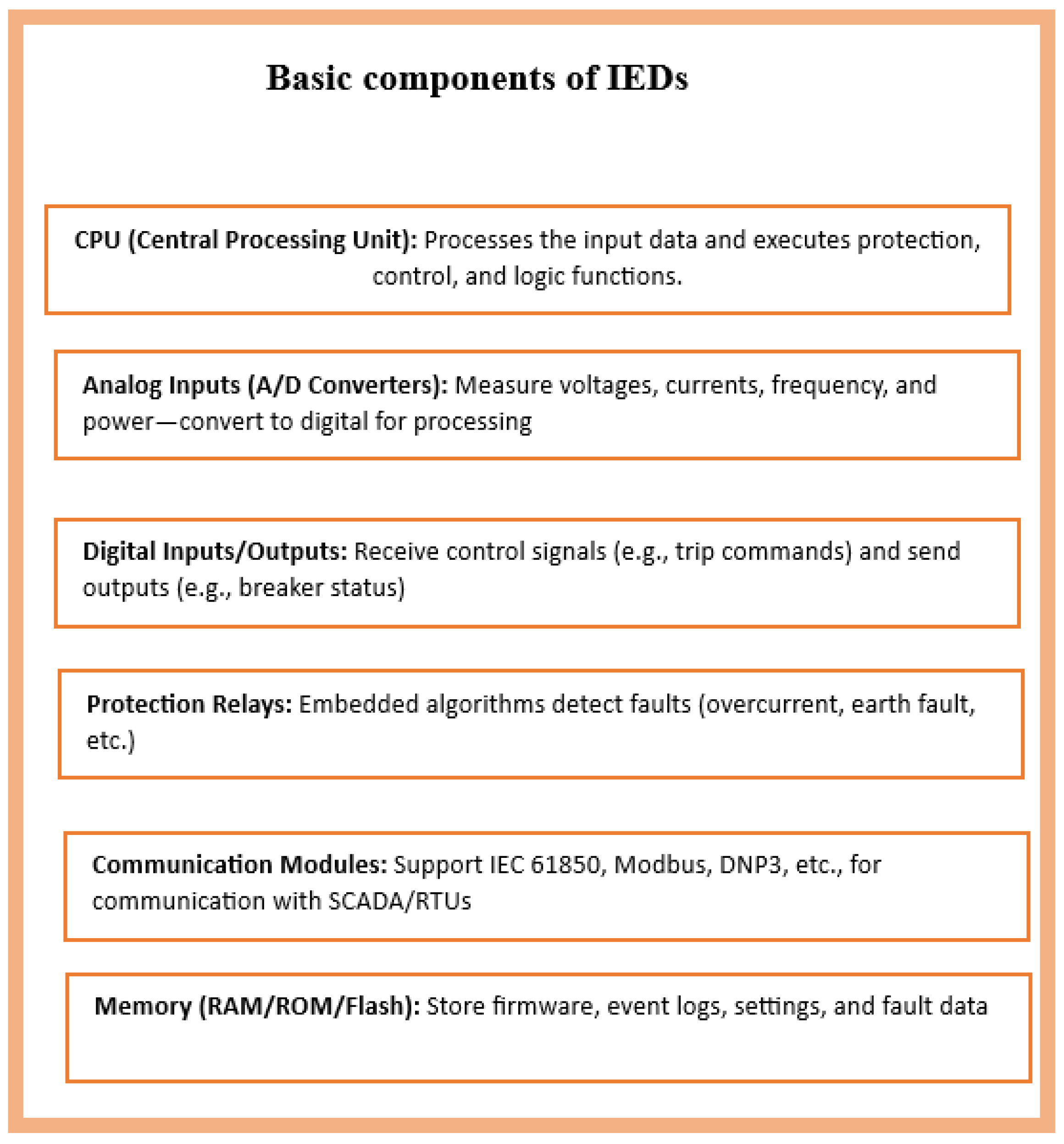
Monitoring: Measuring the voltage, current, and power factor, and recording the real, apparent, and reactive power of each transformer using a sensor (current transformers, CTs; potential transformers, PTs).
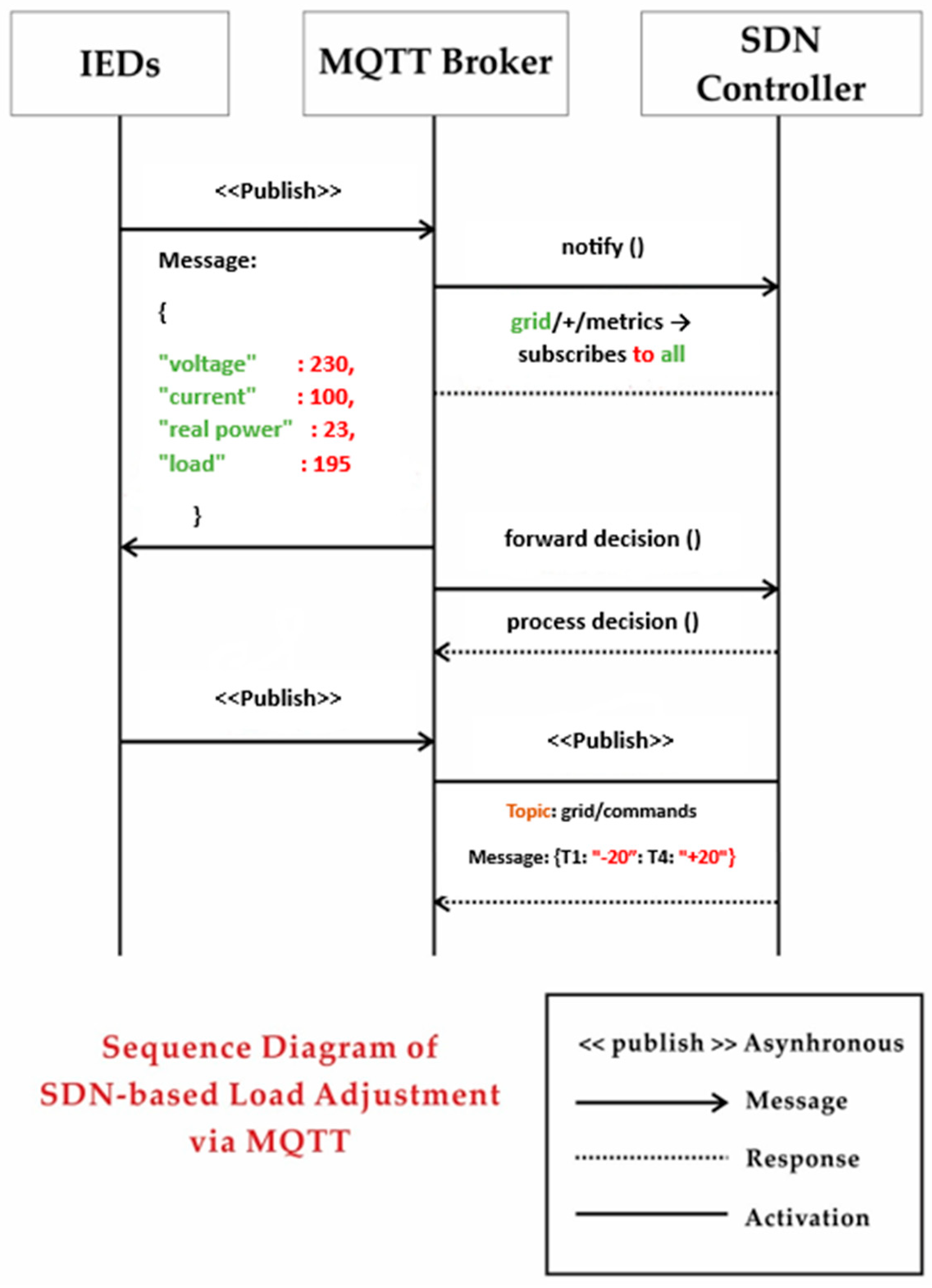
(b)
Communication via Message Queuing Telemetry Transport (MQTT): The data obtained from each transformer is routed to the SDN controller using MQTT communication messenger.
(c)
Action performed as per instruction from SDN controller: Opening and closing of circuit breakers, relays, and rerouting and shift of transformer load as per the instructions of the SDN controller.
Algorithm 2 represents a set of commands used in IEDs to provide aid to the load management process. The first task of the IED is to check the new event that PandaPower has new data in terms of PReal, PReactive, PApparent, and PF. These data logs are converted into Json files to be shared with the SDN controller via the MQTT protocol. The second most important task is to retrieve the message from the MQTT Json file and find the targeted transformers whose loads are to be shifted as per SDN decision logic.
Algorithm 2: Load Condition Monitoring and Alerting System
1.
BEGIN
  • # Check if new load flow results are available from pandapower model
    IF pandapower_model.has_new_results () THEN
    # Receive latest real (P) and reactive (Q) power results
    (PReal, PReactive, PApparent) = pandapower_model.get_load_flow_results ()
    # Format the results into MQTT message (e.g., JSON)
    message = format Message (P, Q)
    # Transmit load flow results to SDN controller
    MQTT_client. publish (results_topic, message) via MQTT
    log (“Published load flow results to controller: PReal=” + PReal + “, PReactive=” + PReactive)
    End If
2.
#check for incoming MQTT messages (from SDN controller)
IF mqtt_client.has_pending_message (command topic) THEN
msg = mqtt_client.get_message(command_topic)              # Retrieve the incoming message
command = parse Command (msg. payload)                      # Parse the SDN command
log (“Received command on MQTT:” + msg. payload)
3.
# --- Condition Check: Identify and handle load shift commands ---
IF command. Type == “LOAD_SHIFT” THEN
source_id = command. source               # e.g., source bus/transformer ID for load reduction
target_id = command.target                   # e.g., target bus/transformer ID for load addition
ΔPReal = command.delta_ PReal            # amount of real power to shift (could be positive or negative)
ΔPReactive = command.delta_PReactive  # amount of reactive power to shift
  log(“Processing load shift: ΔP =” + ΔP + “, ΔQ =” + ΔQ + “ from” + source_id + “to” + target_id)
4.
END
  • Step 3:
The Message Queuing Telemetry Transport (MQTT) acts like an intermediate device for connecting both PandaPower and SDN (Mininet-based) tools. As mentioned earlier, every transformer node is equipped with an IED. When the IED receives load flow analysis by the Panda-Power tool, it sends it to the SDN controller using the MQTT addressing mechanism. We have followed TOPIC syntax, which is case-sensitive and contains all the information about the reading, name, and location of the power device. The data flow using MQTT between IEDs and the SDN controller is shown in Figure 4.
  • Step 4:
The IEDs using the message broker Message Queuing Telemetry Transport (MQTT) guide the SDN controller with the loading scenario of each transformer. Algorithm 3 represents the command used for interfacing IEDs with the SDN controller using MQTT or a shared JSON file as the communication medium. The first statement of the algorithm involves defining the empty directory (IED_status) for storing the load parameter of all transformers (T1–T4). The second and third statements involve the fetching of the SLoad values of each transformer and after rounding off to three decimal points are stored in the IED_status directory with labels T1, T2, etc. In the fourth statement, the directory is converted into standard format (JSON strings) for data transformation over the web. The JSON strings are published to TOPIC (which is the addressing mechanism of the MQTT protocol) named grid/status. The SDN controller will subscribe to this TOPIC (grid/status) and will obtain all the updates from IEDs.
Algorithm 3: IED Status Reporting and MQTT Messaging
1.
BEGIN
# Initialize empty dictionary to hold IED (Intelligent Electronic Device) load status
IEDs_status ← empty_dictionary
2.
# Analyze Load on Each Transformer
FOR each load_index IN network_loads
DO
# Compute (SLoad)
PReal ← get_real_power(load_index)                        Active power in MW
PReactive ← get_reactive_power(load_index)           Reactive power in MVAR
SLoad = PApparent ← sqrt (PReal2 + PReactive2)           Apparent power in MVA
3.
#Round the SLoad value and store it in the dictionary with transformer label
IED_status [“T” + (load_index + 1)] ← round (SLoad, 3)
END FOR
4.
# Convert IED status data to JSON format for transmission
message ← convert_to_JSON (IED_status)
#Simulate sending data via MQTT protocol
PRINT “MQTT Publish Topic: grid/status”
PRINT “Message:”, message
5.
END
It takes 0.5 s for IEDs to detect an abnormality across any branch of the system. The intelligent dynamic load balancing is achieved by loading a Python-based script AI load balancer (AILB) in the form of an Application Programmable Interface (API) via Northbound on the SDN (POX) controller. The AILB-enabled SDN controller takes 1–2 s to redistribute the load to achieve the desired goal as defined in the application layer of the SDN network by the system administrator. The main theme of this AI load balancer script is as follows:
  • Main condition: (If SLoad (any transformer) ≥ 0.90 Rcapacity)
    {
    Shift load to the under-utilized transformer with SLoad (any transformer) ≤ 0.40 Rcapacity
    }
    Else
    {
    Redistribute the load among transformers so that the load parameter satisfies the condition SLoad (all transformers) ≤ 0.70 Rcapacity
    }
  • The pseudocode of the proposed algorithm (AI load balancer) is explained in Algorithm 4. The AILB algorithm first classifies transformers (T1–T4) by their load: those above 90% are classed as overloaded, and those below 40% are classed as under-utilized. The SDN controller shifts load among power transformers as needed to help prevent both scenarios mentioned above. If both defined conditions are met (i.e., there are overloaded and under-utilized transformers in a user-defined system), then the algorithm repeatedly transfers extra load from the overloaded transformer to the under-utilized transformer. If similar transformers cannot be found, the algorithm goes on to a global method, adding all the power together and giving each transformer a load according to their 70% capacity. The outcome is more level use of the network, less chance of transformer damage, and better performance.
Algorithm 4: AI Load Balancer (AILB): Algorithm for Intelligent Dynamic Load Management in Power Transformers
     Input:
     T ← Dictionary mapping transformer ID to current apparent load (SLoad)
     R ← Dictionary mapping transformer ID to rated capacity (Rcapacity)
     Output:
     Updated Load Distribution T after Load Balancing
1.
BEGIN
#Identify overloaded and underutilized transformers
Transformer_Overload ← { t | T[t] ≥ 0.90 × R[t] }
Transformer_Underutilized ← { t | T[t] ≤ 0.40 × R[t] }
2.
# Check load balancing possibility
If Transformer_Overload ≠ ∅ AND Transformer_Underutilized ≠ ∅ then
For each T_o in Transformer_Overload do
For each T_u in Transformer_Underutilized do
transferable ← MIN(T[T_o] − 0.70 × R[T_o], 0.70 × R[T_u] − T[T_u])
If transferable > 0 then
PRINT “Shifting”, transferable, “kVA from”, T_o, “to”, T_u
T[T_o] ← T[T_o] − transferable
T[T_u] ← T[T_u] + transferable
End For
  End For
  3.
Else
  4.
#No clear overload/underload condition – Rebalance all loads fairly
Load_Tot ← SUM over all T[t]
Capacity_Tot ← SUM over all R[t]
For each transformer t in T do
Load_ID ← MIN(0.70 × R[t], Load_Tot × R[t]/Capacity_Tot)
PRINT “Setting load of”, t, “to”, Load_ID
T[t] ← Load_ID
End For
END IF
5.
END
To summarize the logic of the proposed framework for load management in Algorithms 1–4, the UML activity diagram is used and is shown in Figure 5. Figure 5 has three parts: (i) work performed in PandaPower, (ii) the IED and MQTT section, and (iii) the SDN POX controller for managing load by the AILB algorithm. The activity is initialized with the import of the power system, numerical computation library, and the creation of an empty network in the PandaPower tool. In the PandaPower tool, the user-defined topology (alternator as the main source, which is connected with slack buses, and then the slack bus is further connected with four lines connecting four transformers) is created. Initial load parameters are set by the user and sent to load flow analysis for computation (PReal, PReactive, PApparent, PF, and I). These load flow results are then forwarded to the IED. The IED presents these results in data sets in the form of a Json file and forwards the file to the MQTT protocol while waiting for an event to shift load as per instructions of the SDN-based AILB algorithm. The MQTT forwards the Json file to the SDN (POX) controller. The POX controller retrieves the data set from the Json file and, using the AILB algorithm, defines the overloaded (SLoad ≥ 0.90Rcap), under-utilized (SLoad ≤ 0.40Rcap), and normal loaded (SLoad ≤ 0.70Rcap) conditions; then, in light of these conditions, it initiates the comparison of the SLoad of all transformers (T1–T4) with a defined threshold (rated capacity Rcap). If the SLoad of any transformer is greater than or equal to 90% of Rcap, then it is overloaded and the algorithm searches for an under-utilized transformer (among T1–T4). If available, the load of an overloaded transformer is shifted to an under-utilized transformer. If this condition is not met, then it will calculate the total load on the system and divide it among available transformers (T1–T4) so that for all the transformers, SLoad ≤ 0.70Rcap. This decision logic is forwarded back to the IED via the MQTT Json file. The IED that was waiting for an event to shift the load of the overloaded to an under-utilized transformer or shift the load magnitude among all transformers (T1–T4) so that SLoad ≤ 0.70Rcap is satisfied.

3.2. Mathematical Modelling of the Proposed Framework

The details about the mathematical model for intelligent transformer load balancing using SDN-Pandapower via MQTT are explained in Equations (5)–(14) as follows:
  • Let the transformers be denoted as Trans = [Trans_1, Trans_2, Trans_3, Trans_4], and each Trans (i) has rated capacity Rcap(i) in MVA.
  • Load Assigned: Ldi (t) at time t
Apparent   power :   S i ( t ) = V i ( t ) × I i ( t )
Real   power :   P i ( t ) = S i ( t ) .   cos φ i ( t )
Reactive   power :   Q i ( t ) = S i ( t ) .   sin φ i ( t )
Power   factor :   P F i ( t ) = P i ( t ) S i ( t )
  • The load status description is given as follows:
Overload :   S i t 0.90 . R C a p i
Under   load :   S i t 0.40 . R C a p i
Balanced :   S i t 0.70 . R C a p i
  • Main objective function:
m i n L d i ( t ) i = 1 i = 4 S i ( t ) R C a p ( i ) 2 + δ · ( 1 P F s y s t e m t ) , where   δ   is   the   tuning   weight   factor
  • Constraints:
Power   balance :   i = 1 4 L d i ( t ) = L t o t a l ( t )
Transfer   limit :   0 L d i ( t ) R C a p ( i ) t
The   power   factor   of   the   whole   system :   P F s y s t e m t = i = 1 4 P i ( t ) i = 1 4 S i ( t )

3.3. Software/Tools Used in This Co-Simulation Framework

A direct link to the tools/software used is also provided. The list is as follows:
(a)
PandaPower (https://pandapower.readthedocs.io/en/latest/, accessed on 20 April 2025), version 3.1.1.
(b)
Mininet Network Emulator (https://mininet.org/download/, accessed on 20 April 2025), version 2.3.0.
(c)
POX SDN controller (https://brianlinkletter.com/2015/04/using-the-pox-sdn-controller/, accessed on 20 April 2025), version Python 3.
(d)
Gnuplot (http://www.gnuplot.info/download.html, accessed on 20 April 2025), version 6.0.2.

3.4. Simulation Parameters

The details about the simulation parameters for intelligent transformer load balancing using SDN-Pandapower via MQTT are explained in Table 2.

4. Results and Discussions

In this research article, after the establishment of the co-simulation framework, the load flow analysis was performed and all the data was shared with SDN (POX) control, which redirects the load of the transformer as explained in Section 3. The simulation was performed in four different cases. In Case A, we considered all the transformers in the user-defined topology to be under normal operating conditions (as per Equation (11)). In Case B, there is a disturbance in the load parameters of transformers, and the AILB algorithm is not utilized. In Case C, there is the same disturbance in the load parameters of transformers, but the SDN controller is used for redistribution of load based on the AILB algorithm. In Case D, the proposed algorithm is compared with an already-existing algorithm to evaluate the performance. In all four cases, the real power (PReal), reactive power (PReactive), and apparent power (PApparent) are calculated using Equations (16)–(18). The rated capacity (Rcap) of each transformer is (1.0 MVA). The nominal three-phase voltage is 400 v.
P R e a l = 3 × V × I × P F 1000          for   KW
P A p p a r e n t = 3 × V × I 1000                 for   KVA
P R e a c t i v e = ( P A p p a r e n t ) 2 ( P R e a l ) 2

4.1. Case A: We Consider All the Transformers in the User-Defined Topology to Be Under Normal Operating Conditions

In this case, the load flow analysis was performed with the PandaPower Simulink tool, and no help was provided by the SDN controller. The data was analysed for the Simulink time (t = 10 s). We assume this case is an ideal condition with load parameters on all the transformers below 70 percent of their rated capacity (i.e., ≤0.70). The result of the power load flow analysis is shown in Table 3.

Summary of Results in Case A

In this case, the percentage loads on the transformers (Trans_1, Trans_2, Trans_3, and Trans_4) are 60%, 50%, 50%, and 60%. All the values are below the assumed balanced scenario (Si (t) ≤ 0.70 Rcap(i)). The overall power factor of the system as well as all four transformers (Trans_1, Trans_2, Trans_3, and Trans_4) is 0.95, obtained from PApparent (631.59, 526.309, 526.309, 631.59) in KVA and PReactive (204.9, 165.29, 165.29, 204.9) in KVAR, respectively. The three-phase nominal voltage for all transformers (Trans_1, Trans_2, Trans_3, and Trans_4) is 400 V.

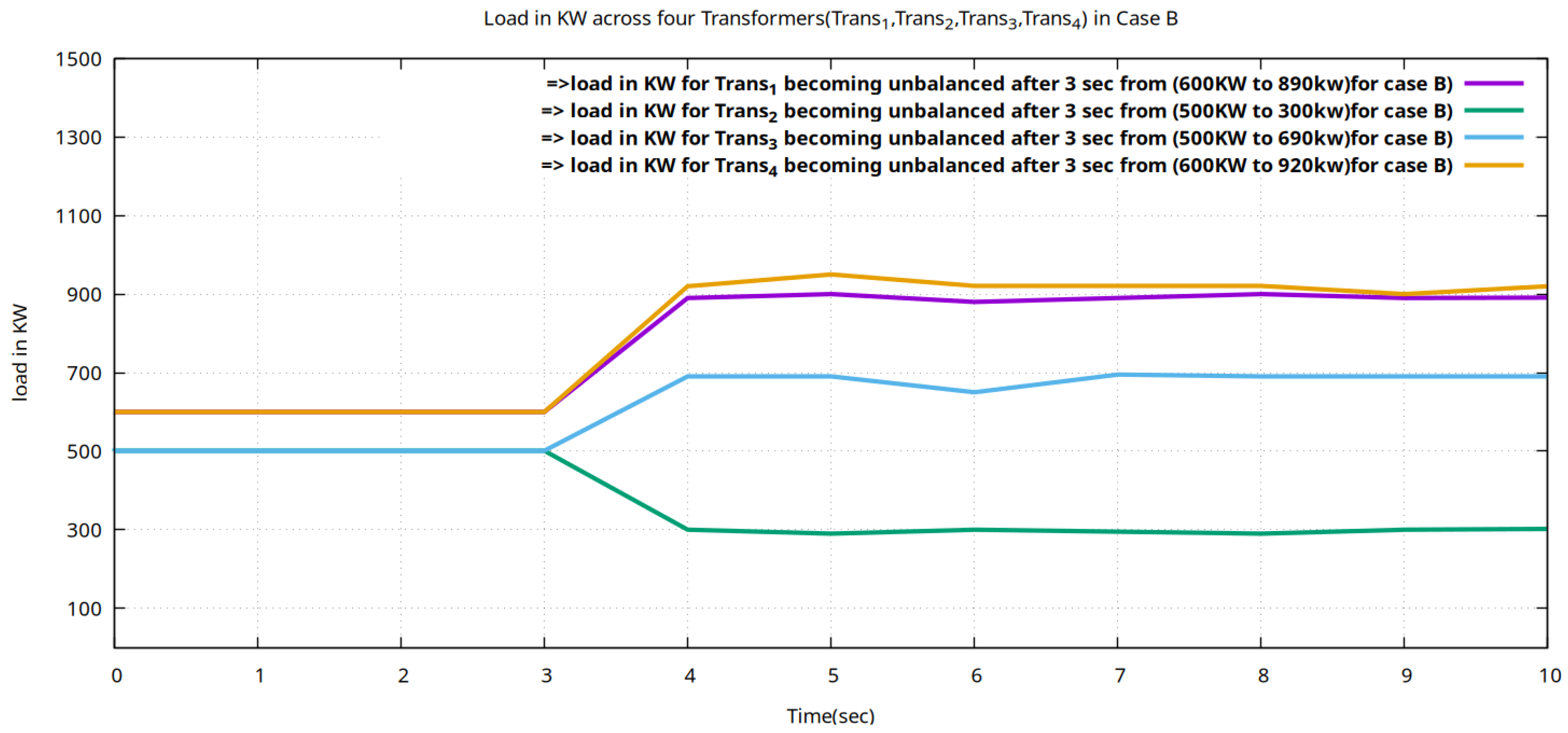
4.2. Case B: There Is a Disturbance in the Load Parameters of Transformers and the AILB Algorithm Is Not Utilized

In this case, the load flow analysis is performed with the PandaPower tool for 10 s, and no help was provided by the SDN controller to manage the load parameter abnormalities. The result of the power load flow analysis is shown in Table 4.
We have designed a scenario in which the load on all four transformers (Trans_1, Trans_2, Trans_3, and Trans_4) remains normal (same value as in Case A as shown in Table 3), but after 3 s the load is unbalanced (as shown in Table 4). The Gnu-Plot is used to draw the responses obtained from load flow analysis. Figure 6 and Figure 7 show the load (KW) on each transformer and system power factor in comparison with the power factor of all transformers, respectively.

Summary of Results in Case B

In this case, the percentage loads on the transformers (Trans_1, Trans_2, Trans_3, and Trans_4) are 89%, 30%, 69%, and 92%. All the values show abnormal load distribution across the power transformer. Due to uneven load distribution, the current drawn in Trans_1, Trans_3, and Trans_4 is increased (1429.49 A, 456.59 A, 1047.59 A, and 1510.11 A), the demand of PReactive (430.79 KVAR, 98.19 KVAR, 227.29 KVAR, and 456.89 KVAR) is increased, and the power factor of these transformers and the overall system power factor (0.91) are also decreased.

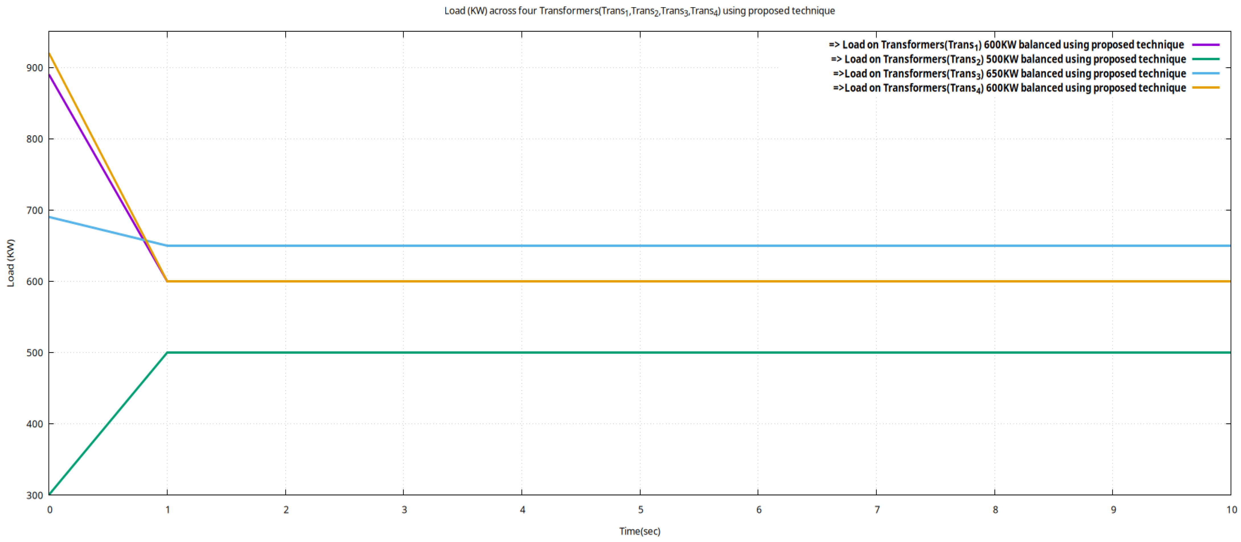
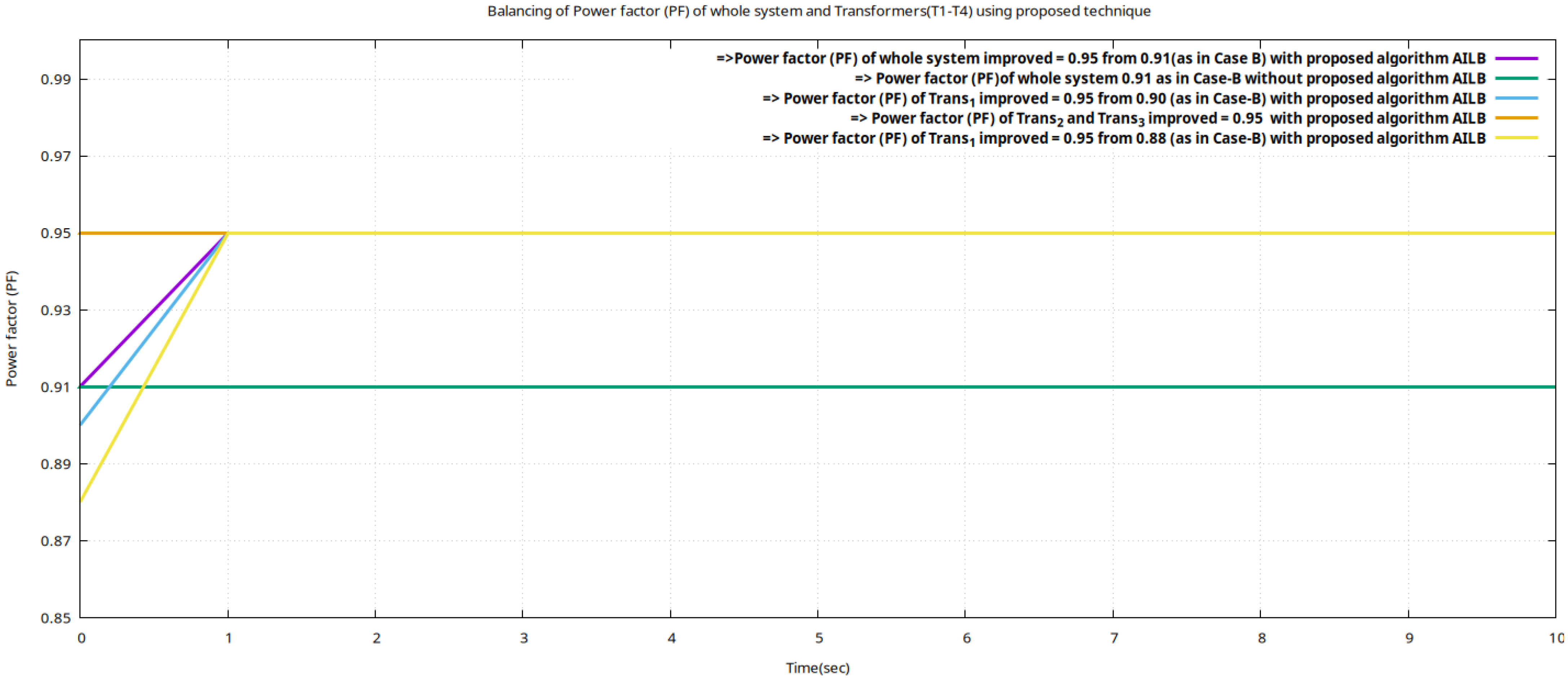
4.3. Case C: Redistributing Load Parameters of Transformers with the AILB Algorithm

In this case, the load flow analysis is performed with the PandaPower tool for 10 s. The IEDs using the message broker Message Queuing Telemetry Transport (MQTT) guide the SDN controller in the loading scenario of each transformer within 0.5 s. The intelligent dynamic load balancing is achieved by loading a Python-based script AI load balancer (AILB) in the form of an Application Programmable Interface (API) via Northbound on the SDN (POX) controller within 0.5 s after the sensing time of the IEDs. The main theme of this AI load balancer script is as follows:
  • Main condition: If (SLoad (any Transformer) ≥ 0.90 Rcapacity)
    {
    Shift load to the under-utilized transformer with SLoad (any transformer) ≤ 0.40 Rcapacity
    }
    Else
    {
    Redistribute the load among transformers so that the load parameter satisfies the condition SLoad (all transformers) ≤ 0.70 Rcapacity
    }
  • The result of the power load flow analysis is shown in Table 5.
Table 5. Load flow analysis for Case C.
TransformerRCap (KVA)%LPReal (KW)PApparent (KVA)PReactive (KVAR)Current (A)Voltage (V)PF
Trans_1100060600631.59197912.14000.95
Trans_2100050500526.29164.49759.94000.95
Trans_3100065650684.19213.19987.214000.95
Trans_4100060600631.59197.01912.14000.95
Total1000-23502473.69771.69-4000.95 (Bal)
The Gnu-Plot is used to draw the responses obtained from load flow analysis. Figure 8 and Figure 9 show the load (KW) on each transformer and system power factor in comparison with the power factor of all transformers and that of the system power factor in Case A and Case B.
In Figure 8 we can see that it takes a response time of 1 s for the AILB-based SDN controller to operate and redistribute the load and modify load parameters on each transformer. Regarding Table 5, the load on the transformer (Trans_1) is redistributed and shifted to the value of 600 KW from 890 KW to reduce the large current drawn and minimize the need to supply reactive power. The load on the transformer (Trans_2) is redistributed and shifted to the value of 300 KW from 500 KW (under loading conditions to balance the load) to share a load of another transformer to enhance the overall power factor of the system. Meanwhile, the transformer Trans_3 was already in a balanced condition. Similarly, the load on the transformer Trans_4 is redistributed and shifted to the value of 600 KW from 920 KW to reduce the large current drawn and minimize the need to supply reactive power.
In Figure 9 we can see that it takes a response time of 1 s for an AILB-based SDN controller to operate and redistribute the load and modify load parameters on each trans-former to enhance its power factor, which will ultimately result in enhancement in the power factor of the whole system (from 0.91 to 0.95). In this case, the power factor across the transformer (Trans_1 and Trans_4) is enhanced to an ideal level (0.95) as in Case A.

Summary of Results in Case C

In this case, abnormality in the percentage load on the transformers (Trans_1, Trans_2, Trans_3, and Trans_4) is managed by using the SDN-based AILB algorithm. Due to even load distribution, the current (912, 759.9, 987.21, and 912.1) in Amperes drawn across Trans_1, Trans_2, Trans_3, and Trans_4 is normalized as compared to the load flow result in Case B, the demand of PReactive (197, 164.49, 213.19, and 197.01 in KVAR) is decreased, and the power factor of these transformers and overall system power factor (0.95) are also increased as compared to the results in Case B in a total response time of 1 s.

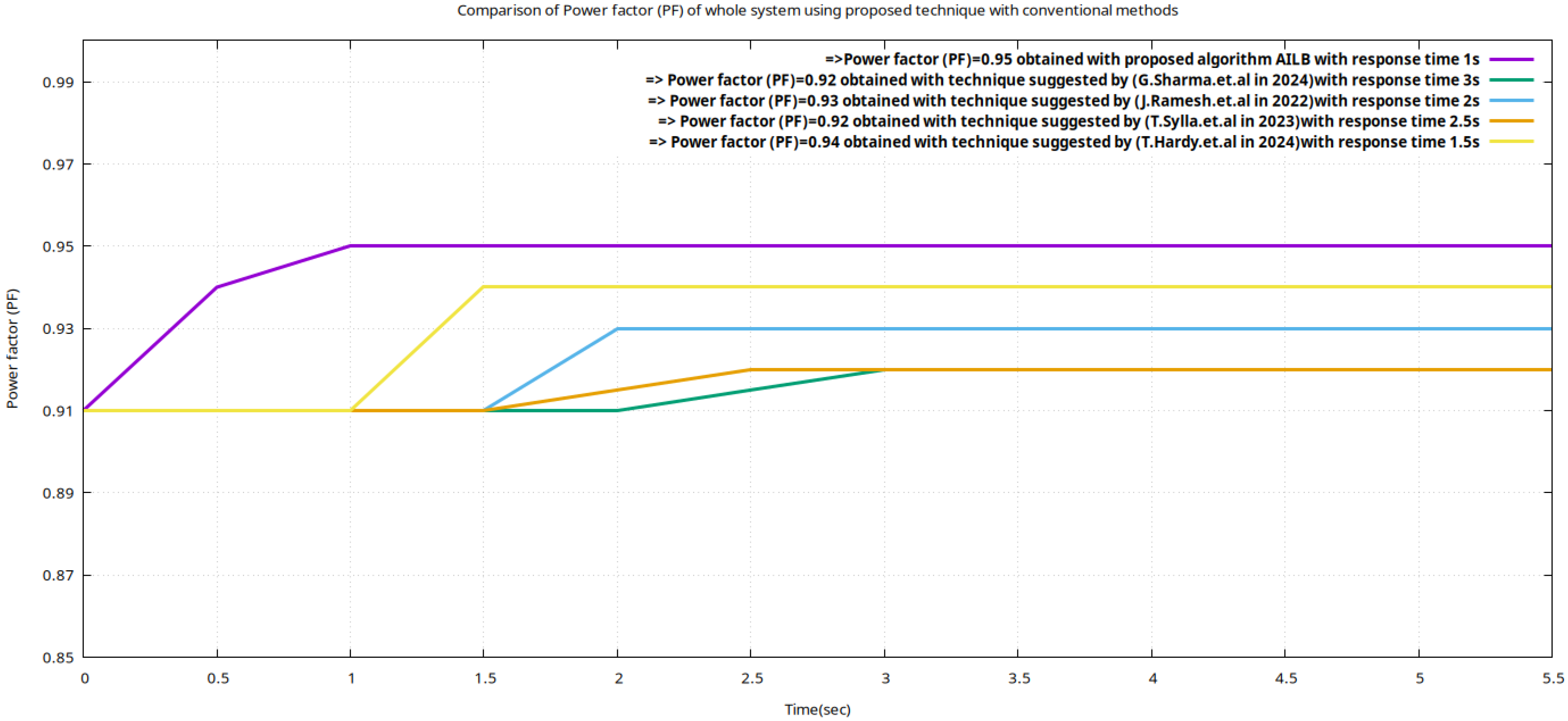
4.4. Case D: The Proposed Algorithm (AILB) Is Compared with an Already-Existing Algorithm to Evaluate the Performance

In this case, the performance of the proposed technique is evaluated by considering the same scenario of abnormality of load in the transformer (as discussed in Case B) and comparing the simulation results of load flow analysis on user-defined network topology for t = 10 s by the method suggested in the research articles [41,42,43,44] due to its close similarity to our proposed method. The Case B scenario is chosen to draw the comparison, while in this case, the overall system power factor with un-justified load distribution was 0.91. The comparative results of load flow analysis while considering the load parameters abnormalities of Case B are shown in Table 6.
Figure 10 shows the comparisons of the system power factor obtained from the proposed method and that of an already-existing method.
In this case, abnormality in the percentage load on the transformers (Trans_1, Trans_2, Trans_3, and Trans_4) is efferently managed by using the SDN-based AILB algorithm. Due to better load distribution using SDN-enabled AILB, the current in Amperes drawn across Trans_1, Trans_2, Trans_3, and Trans_4 is normalized within the minimum response time (within 1 s) as compared to other techniques (discussed in research articles [41,42,43,44]). The power factor of an overall system using the proposed framework is 0.95 as compared to the research method in [41,42,43,44].

Summary of Results in Case D

The load flow analysis in Table 6 shows that the proposed technique’s performance is far superior to the already-existing method. The demand for PReactive is decreased, with an enhanced overall system power factor that is within the minimum response time as compared to the conventional load-balancing method.

5. Conclusions

This research method proposed an intelligent, real-time, dynamic load management system for transformer operations in modern grid systems. The main aim of this proposed SDN-enabled (AILB) method was (a) to monitor real-time transformer load data, (b) to enable the SDN (POX) controller to redistribute load and prevent overloading phenomena, and (c) to improve system efficiency, reduce transformer overloading, maintain a high power factor, and minimize losses. This simulation is performed in four different cases. In Case A, we consider all the transformers in the user-defined topology to be under normal operating conditions. In Case B, there is a disturbance in the load parameters of the transformers, and the AILB algorithm is not utilized. In Case C, there is the same disturbance in the load parameters of the transformers, but the SDN controller is used for the redistribution of load based on the AILB algorithm. In Case D, the proposed algorithm is compared with an already-existing algorithm to evaluate the performance.
The result shows that when the proposed algorithm is not used with abnormal load distribution, the current drawn in Trans_1, Trans_2 Trans_3, and Trans_4 is increased (1429.49 A, 456.59 A, 1047.59 A, and 1510.11 A), the demand of PReactive (430.79 KVAR, 98.19 KVAR, 227.29 KVAR, and 456.89 KVAR) is also increased, and the power factor of these transformers and the overall system power factor (0.91) are also decreased. However, with the application of the proposed technique, the abnormality in the percentage load on the transformers (Trans_1, Trans_2, Trans_3, and Trans_4) is managed by using the SDN-based AILB algorithm. Due to even load distribution, the current (912 A, 759.9 A, 987.21 A, and 912.1 A) in Amperes drawn across Trans_1, Trans_2, Trans_3, and Trans_4 is normalized as compared to the load flow result in Case B; the demand of PReactive (197, 164.49, 213.19, and 197.01 in KVAR) is decreased; and the power factor of these transformers and the overall system power factor (0.95) are also increased as compared to the results in Case B. In the end, the performance of the proposed technique was evaluated by considering the same scenario of abnormality of load in the transformer (as discussed in Case B) and comparing the simulation results of load flow analysis on user-defined network topology for t = 10 s by the method suggested in research articles [41,42,43,44] due to its close similarity with our proposed method. The result shows that the abnormality in the percentage load on the transformers (Trans_1, Trans_2, Trans_3, and Trans_4) is efferently managed by using the SDN-based AILB algorithm. Due to better load distribution using SDN-enabled AILB, the current in Amperes drawn across Trans_1, Trans_2, Trans_3, and Trans_4 is normalized within the minimum response time (within 1 s) as compared to the techniques discussed in research articles [41,42,43,44]. The power factor of an overall system using the proposed framework is 0.95 as compared to the research method [41,42,43,44]. However, the modelling of inverter behaviour, particularly their dynamic response or “race” under a fast-changing load or control instructions is very crucial. However, we recognize that to move toward implementation readiness, it is essential to incorporate fast-acting inverter control dynamics, which we plan to integrate into future iterations of the framework.

Author Contributions

Study conception and design: K.T.M. and M.M.H.; data collection: K.T.M. and M.M.H.; analysis and interpretation of results: K.T.M. and M.M.H.; draft manuscript preparation: K.T.M. and M.M.H. All authors have read and agreed to the published version of the manuscript.

Funding

This research received no funding.

Institutional Review Board Statement

Not Applicable.

Informed Consent Statement

Not applicable.

Data Availability Statement

Data is available with the corresponding author upon appropriate request.

Conflicts of Interest

The authors declare no conflicts of interest.

References

  1. Syed, D.; Abu-Rub, H.; Ghrayeb, A.; Refaat, S.S.; Houchati, M.; Bouhali, O. Deep Learning-Based Short-Term Load Forecasting Approach in Smart Grid with Clustering and Consumption Pattern Recognition. IEEE Access 2021, 9, 54992–55008. [Google Scholar] [CrossRef]
  2. Amrita, A.A.N.; Ariastina, W.G.; Manuaba, I.B.G. Study of Transformer Lifetime Due to Loading Process on 20 KV Distribution Line. J. Electr. Electron. Inform. 2018, 2, 25–28. [Google Scholar] [CrossRef]
  3. Che, J.; Park, G.; Oh, J.; Pyo, S.H.; An, B.; Park, T. Power Transformer Health Index Using Cost-Sensitive Learning to Consider the Impact of Misclassification. IEEE Access 2024, 12, 191790–191807. [Google Scholar] [CrossRef]
  4. Lv, L.; Han, Y. Identification of Transformer Overload and New Energy Planning for Enterprises Based on Load Forecasting. PLoS ONE 2024, 19, e0311354. [Google Scholar] [CrossRef] [PubMed]
  5. Pijarski, P.; Kacejko, P. Elimination of Line Overloads in a Power System Saturated with Renewable Energy Sources. Energies 2023, 16, 3751. [Google Scholar] [CrossRef]
  6. Taheri, S.; Gholami, A.; Fofana, I.; Taheri, H. Modeling and Simulation of Transformer Loading Capability and Hot Spot Temperature under Harmonic Conditions. Electr. Power Syst. Res. 2012, 86, 68–75. [Google Scholar] [CrossRef]
  7. Velasquez, W.; Moreira-Moreira, G.Z.; Alvarez-Alvarado, M.S. Smart Grids Empowered by Software-Defined Network: A Comprehensive Review of Advancements and Challenges. IEEE Access 2024, 12, 63400–63416. [Google Scholar] [CrossRef]
  8. Rehmani, M.H.; Davy, A.; Jennings, B.; Assi, C. Software Defined Networks-Based Smart Grid Communication: A Comprehensive Survey. IEEE Commun. Surv. Tutor. 2019, 21, 2637–2670. [Google Scholar] [CrossRef]
  9. Islam, M.; Ismail, M.; Atat, R.; Boyaci, O.; Shannigrahi, S. Software-Defined Network-Based Proactive Routing Strategy in Smart Power Grids Using Graph Neural Network and Reinforcement Learning. e-Prime Adv. Electr. Eng. Electron. Energy 2023, 5, 100187. [Google Scholar] [CrossRef]
  10. Owusu, E.T.; Agyekum, K.A.P.; Benneh, M.; Ayorna, P.; Agyemang, J.O.; Colley, G.N.M.; Gazde, J.D. A Transformer-Based Deep Q Learning Approach for Dynamic Load Balancing in Software-Defined Networks. arXiv 2025, arXiv:2501.12829. [Google Scholar] [CrossRef]
  11. Arbab-Zavar, B.; Palacios-Garcia, E.J.; Vasquez, J.C.; Guerrero, J.M. Message Queuing Telemetry Transport Communication Infrastructure for Grid-Connected AC Microgrids Management. Energies 2021, 14, 5610. [Google Scholar] [CrossRef]
  12. Akrami, A.; Doostizadeh, M.; Aminifar, F. Power System Flexibility: An Overview of Emergence to Evolution. J. Mod. Power Syst. Clean Energy 2019, 7, 987–1007. [Google Scholar] [CrossRef]
  13. Hadi, M.B.; Moeini-Aghtaie, M.; Khoshjahan, M.; Dehghanian, P. A Comprehensive Review on Power System Flexibility: Concept, Services, and Products. IEEE Access 2022, 10, 99257–99267. [Google Scholar] [CrossRef]
  14. Tiismus, H.; Maask, V.; Astapov, V.; Korõtko, T.; Rosin, A. State-of-the-Art Review of Emerging Trends in Renewable Energy Generation Technologies. IEEE Access 2025, 13, 10820–10843. [Google Scholar] [CrossRef]
  15. Rahman, M.M.; Dadon, S.H.; He, M.; Giesselmann, M.; Hasan, M.M. An Overview of Power System Flexibility: High Renewable Energy Penetration Scenarios. Energies 2024, 17, 6393. [Google Scholar] [CrossRef]
  16. Heggarty, T.; Bourmaud, J.Y.; Girard, R.; Kariniotakis, G. Quantifying Power System Flexibility Provision. Appl. Energy 2020, 279, 115852. [Google Scholar] [CrossRef]
  17. Babatunde, O.M.; Munda, J.L.; Hamam, Y. Power System Flexibility: A Review. Energy Rep. 2020, 6 (Suppl. 2), 101–106. [Google Scholar] [CrossRef]
  18. Ojo, O.T.; Salman, M.B.; Agbanusi, I.L.; Azubuike, C.H.; Olaleye, T.G.; Oyesanya, A.; Ajiboye, J.A. Enhancing Power Grid Resilience Through Energy Storage and Demand Response. Path Sci. 2025, 11, 8023–8029. Available online: https://pathofscience.org/index.php/ps/article/view/3453 (accessed on 20 April 2025). [CrossRef]
  19. Hinov, N. Smart Energy Systems Based on Next-Generation Power Electronic Devices. Technologies 2024, 12, 78. [Google Scholar] [CrossRef]
  20. Moreno Escobar, J.J.; Morales Matamoros, O.; Tejeida Padilla, R.; Lina Reyes, I.; Quintana Espinosa, H. A Comprehensive Review on Smart Grids: Challenges and Opportunities. Sensors 2021, 21, 6978. [Google Scholar] [CrossRef]
  21. Chaudhary, R.; Aujla, G.S.; Kumar, N.; Chouhan, P.K. A Comprehensive Survey on Software-Defined Networking for Smart Grid Communications. Int. J. Commun. Syst. 2022, 35, e5296. [Google Scholar] [CrossRef]
  22. Urrea, C.; Benítez, D. Software-Defined Networking Solutions, Architecture and Controllers for the Industrial Internet of Things: A Review. Sensors 2021, 21, 6585. [Google Scholar] [CrossRef] [PubMed]
  23. Wendneso, A.; Rakissaga, O.; Omar, H.H.H.; Kouraogo, P.J.; Green, L. Software Defined Networks: Strengths, Weaknesses, and Resilience. Engineering 2025, 17, 19–29. [Google Scholar] [CrossRef]
  24. Mohandes, B.; Moursi, M.S.E.; Hatziargyriou, N.; Khatib, S.E. A Review of Power System Flexibility with High Penetration of Renewables. IEEE Trans. Power Syst. 2019, 34, 3140–3155. [Google Scholar] [CrossRef]
  25. Impram, S.; Nese, S.V.; Oral, B. Challenges of Renewable Energy Penetration on Power System Flexibility: A Survey. Energy Strategy Rev. 2020, 31, 100539. [Google Scholar] [CrossRef]
  26. Bretas, A.; Agnew, D.; Boamah, S.; McNair, J. Network Security Challenges and Countermeasures for Software-Defined Smart Grids: A Survey. Smart Cities 2024, 7, 2131–2181. [Google Scholar] [CrossRef]
  27. Agnew, D.; Boamah, S.; McNair, J. A Survey of Software-Defined Smart Grid Networks: Security Threats and Defense Techniques. arXiv 2023, arXiv:2306.14697. [Google Scholar] [CrossRef]
  28. Kumar, P.; Kumar, R.; Aljuhani, A.; Javeed, D.; Jolfaei, A.; Islam, A.K.M.N. Digital Twin-Driven SDN for Smart Grid: A Deep Learning Integrated Blockchain for Cybersecurity. Sol. Energy 2023, 263, 111921. [Google Scholar] [CrossRef]
  29. Zion Market Research. Intelligent Electronic Devices Market Size, Share Analysis, and Forecast 2024–2032. 2024. Available online: https://www.zionmarketresearch.com/report/intelligent-electronic-devices-market (accessed on 20 April 2025).
  30. IMARC Group. Intelligent Electronic Devices Market: Global Industry Trends, Share, Size, Growth, Opportunity and Forecast 2024–2033. 2024. Available online: https://www.imarcgroup.com/intelligent-electronic-devices-market (accessed on 20 April 2025).
  31. Introspective Market Research. Intelligent Electronic Devices Market Analysis 2024–2032: Trends, Drivers, Challenges, and Quantitative Insights. 2024. Available online: https://introspectivemarketresearch.com/reports/intelligent-electronic-devices-market/ (accessed on 20 April 2025).
  32. Qi, S.; Wang, X.; Li, X.; Qian, T.; Zhang, Q. Enhancing Integrated Energy Distribution System Resilience through a Hierarchical Management Strategy in District Multi-Energy Systems. Sustainability 2019, 11, 4048. [Google Scholar] [CrossRef]
  33. Emmanuel, M.; Doubleday, K.; Cakir, B.; Marković, M.; Hodge, B.M. A review of power system planning and operational models for flexibility assessment in high solar energy penetration scenarios. Solar Energy 2020, 210, 169–180. [Google Scholar] [CrossRef]
  34. Shahzad, S.; Jasińska, E. Renewable Revolution: A Review of Strategic Flexibility in Future Power Systems. Sustainability 2024, 16, 5454. [Google Scholar] [CrossRef]
  35. Salman, U.T.; Shafiq, S.; Al-Ismail, F.S.; Khalid, M. A Review of Improvements in Power System Flexibility: Implementation, Operation, and Economics. Electronics 2022, 11, 581. [Google Scholar] [CrossRef]
  36. Khan, R.H.; Khan, J.Y. A comprehensive review of the application characteristics and traffic requirements of a smart grid communications network. Comput. Netw. 2013, 57, 825–845. [Google Scholar] [CrossRef]
  37. Shaileshwari, M.U.; Nandini Prasad, K.S.; Paventhan, A. Software Defined Networking for Smart Grid Communications and Security Challenges. In ISGW 2017: Compendium of Technical Papers; Pillai, R., Ghatikar, G., Seethapathy, R., Sonavane, V.L., Khaparde, S.A., Yemula, P.K., Chaudhuri, S., Venkateswaran, A., Eds.; Lecture Notes in Electrical Engineering; Springer: Singapore, 2018; Volume 487. [Google Scholar] [CrossRef]
  38. Pfeiffenberger, T.; Du, J.L. Evaluation of Software-Defined Networking for Power Systems. In Proceedings of the 2014 IEEE International Conference on Intelligent Energy and Power Systems (IEPS), Kyiv, Ukraine, 2–6 June 2014; pp. 181–185. [Google Scholar] [CrossRef]
  39. Zhou, B.; Zou, J.; Chung, C.Y.; Wang, H.; Liu, N.; Voropai, N.; Xu, D. Multi-Microgrid Energy Management Systems: Architecture, Communication, and Scheduling Strategies. J. Mod. Power Syst. Clean Energy 2021, 9, 463–476. [Google Scholar] [CrossRef]
  40. Msane, M.R.; Thango, B.A.; Ogudo, K.A. Condition Monitoring of Electrical Transformers Using the Internet of Things: A Systematic Literature Review. Appl. Sci. 2024, 14, 9690. [Google Scholar] [CrossRef]
  41. Sharma, G.; Raju, V.V.; Dhall, H.; Sudan, P.; Reddy, B.; Alpackaya, I. Fuzzy Logic-Based Energy Management in Smart Grids for Renewable Integration. E3S Web Conf. 2024, 511, 01013. [Google Scholar] [CrossRef]
  42. Ramesh, J.; Shahriar, S.; Al-Ali, A.R.; Osman, A.; Shaaban, M.F. Machine Learning Approach for Smart Distribution Transformers Load Monitoring and Management System. Energies 2022, 15, 7981. [Google Scholar] [CrossRef]
  43. Sylla, T.; Singh, R.; Mendiboure, L.; Berger, M.S.; Berbineau, M.; Dittmann, L. SoD-MQTT: A SDN-Based Real-Time Distributed MQTT Broker. In Proceedings of the 2023 19th International Conference on Wireless and Mobile Computing, Networking and Communications (WiMob), Montreal, QC, Canada, 21–23 June 2023; pp. 92–97. [Google Scholar] [CrossRef]
  44. Hardy, T.D.; Palmintier, B.; Top, P.L.; Krishnamurthy, D.; Fuller, J.C. HELICS: A Co-Simulation Framework for Scalable Multi-Domain Modeling and Analysis. IEEE Access 2024, 12, 24325–24347. [Google Scholar] [CrossRef]
Figure 1. The working model of the SDN regarding load management of a power plant.
Energies 18 03001 g001
Figure 2. The proposed co-simulation framework (Panda-SDN Load Balancer) working model.
Energies 18 03001 g002
Figure 3. Basic working components inside IEDs.
Energies 18 03001 g003
Figure 4. The flow of data between IEDs and SDN using MQTT.
Energies 18 03001 g004
Figure 5. UML activity diagram indicating the working of the proposed framework.
Energies 18 03001 g005
Figure 6. Load (KW) on each transformer (Trans_1, Trans_2, Trans_3, and Trans_4) for Case B.
Energies 18 03001 g006
Figure 7. The system power factor in comparison with the power factor of all transformers for Case B.
Energies 18 03001 g007
Figure 8. Redistribution of load (KW) on each transformer (Trans_1, Trans_2, Trans_3, and Trans_4) using the proposed technique after 1 s (within 0.5 s of IEDs sensing).
Energies 18 03001 g008
Figure 9. Enhancement in system power factor with the proposed technique in 1 s in comparison with system power factor for Case B.
Energies 18 03001 g009
Figure 10. Enhancement in system power factor by comparing the proposed algorithm (AILB) with already-existing algorithms [41,42,43,44].
Energies 18 03001 g010
Table 1. Contributions and limitations of techniques used by different authors to enhance the efficiency of power grid.
ReferencesContribution of Author’s TechniqueLimitation and Comparison with the Proposed Technique
A. Akrami et al. [12]This study highlights the different operational evaluation methods to enhance power system flexibility.Lacks practical implementations and no work on the implementation of SDN or IED integration for increased flexibility of power system.
M.B. Hadi et al. [13]This study provides a review of modelling techniques.Focused heavily on theoretical detail of power system failure with negligible coverage of modern communication technologies such as SDN or MQTT.
H. Tiismus et al. [14]Analyses the impact of renewable energy and provides mitigation techniques.No work on AI-based techniques to balance the load.
M.M. Rehman et al. [15]Proposes methods for quantifying the flexibility of power grids at the planning and operation stages.Lacks practical implementations and no work on the implementation of SDN or IEDs.
T. Heggarty et al. [16]Presents a categorization of flexibility resources and requirements under the smart grid. No work on AI-based techniques to balance the load.
O.M. Babatunde et al. [17]Advancements in renewable energy systems that influence grid flexibility. No integration of SDN, AI-driven management, or IED data analysis.
O.T. Ojo et al. [18]This study explains the demand response and storage systems to improve grid flexibility.Does not explain the intelligent load redistribution or network optimization using SDN.
N. Hinov et al. [19]Design of smart converters for smart energy management.No real-time communication protocols like MQTT or SDN used.
J.J. Moreno Escobar et al. [20]Review the linking SDN to the grid system.Lacks practical implementations.
R. Chaudhary et al. [21]Analysis of SDN architecture in smart grids.No real-time power system simulations like Panda_Power or MQTT.
C. Urrea et al. [22]Using SDN to optimize network flows in an IoT-based industrial system.No power simulation is performed.
A. Wendneso et al. [23]SDN’s fault tolerance and scalability in power grids.Lacks implementation of frameworks such as IEDs and MQTT-based data exchange.
M.B. Mohande et al. [24]Provides modelling of matrices (generation-side, demand-side, and grid-side).No integration of SDN to automate flexibility assessment.
S. Impram et al. [25]Operational flexibility and scenario modelling.The system is modelled conventionally, without AI control logic or via SDN.
A. Bretas et al. [26]SDN security layers, flaws in flow tables, controller attacks, and data integrity threats.No simulation of SDN in load management scenarios.
D. Agnew et al. [27]The use of machine learning techniques to overcome the threats and mitigation techniques in SDN-controlled grid environments.No integration of IEDs and MQTT-based brokers.
P. Kumar et al. [28]SDN with digital twin models to improve energy dispatch.Lacks consideration of specific transformer-level decision loops that employ feedback via MQTT or IEDs.
Zion Market Research [29]Role of IEDs in energy distribution.Transformer interaction modelling is absent.
IMARC Group et al. [30]Examines IEDs in distribution and transmission networks.AI-based load optimization, SDN controllers, and data-gathering architectures were not discussed.
Introspective Market Research et al. [31]Evaluates IED deployment trends, drivers, and technology prospects in grid automation and digital substations.No integration of IEDs with co-simulation platforms, SDN, or MQTT.
S. Qi et al. [32]Adoption of IEDs for reducing operational costs in smart grids.Lacks technical validation of IEDs’ support for real-time control, AI, or SDN-based management.
M.Emmanuel et al. [33]Load flow and transient stability modelling using Python-based tools.No integration of messaging layers like MQTT or network controllers like POX/SDN.
S. Shahzad et al. [34]Co-simulation using HELICS to synchronize grid models and communication frameworks.No AI-based load decision logic or demonstration with MQTT-enabled IED communication.
Umar Taiwo Salman et al. [35]Combines artificial intelligence algorithms for transformer load forecasting and balance decisions with IED-based data monitoring.No integration with SDN-based control planes or communication brokers; offline modelling of implementation.
H. R. Khan et al. [36]Suggests an MQTT-based architecture that monitors and powers quality parameters in real time.Does not apply load balancing methods or combine MQTT communications with SDN.
M.U. Shaileshwari et al. [37]Examines the use of synchronized phasor readings for better operational decision-making.Does not integrate with real-time data-sharing protocols such as MQTT or SDN control planes.
Thomas Pfeiffenberger et al. [38]Optimizes grid load balancing by combining SDN with fuzzy logic.Does not incorporate IEDs or MQTT.
B. Zhou et al. [39]Explains how to acquire transformer health data with low latency using MQTT.Does not simulate the AI-based redistribution or SDN-driven control choices.
M.R. Msane et al. [40]Automates decisions about distributed load shedding and shifting in smart grid nodes using reinforcement learning.The method is decentralized and does not provide support for controller-based SDN installation.
G. Sharma et al. [41]Intelligent load balancing in smart grids using SDN + fuzzy logic.No MQTT or IED feedback, no simulation model.
J. Ramesh et al. [42]Real-time load estimation on transformers using IED data + AI for balancing.No programmable SDN control or flow shifting.
T. Sylla et al. [43]A platform for monitoring smart substations using SDN and MQTT. No load shifting or AI-based redistribution.
T. Hardy et al. [44]Synchronizes cyber and physical layers using HELICS and Power_Sim.No AI or SDN-based policy logic.
Table 2. Simulation parameters for intelligent transformer load balancing using SDN-Pandapower via MQTT.
ParametersDescriptionsValues
Trans (1–4)Number of transformers4
RcapRated capacityI.0 MVA for all four transformers
VNominal voltage11 kv
FFrequency50 hz
ALTcapAlternator rated capacity50 MVA
SDN controllerType of SDN controller usedPOX
OverloadingLoad threshold for overloading≥0.90
Under loadingLoad threshold for under loading≤0.40
Balanced loadingLoad threshold for balanced loading≤0.70
IED configurationMeasurement (voltage, current, real power, apparent power, and power factor)V, I, P, S, PF
ProtocolIntegration between Pandapower and SDNMQTT via IEDs
MQTT addressLocal hostPort number 1883
MQTT (TOPICS)Addressing mechanism adoptedGrid/load, Grid/status
Table 3. Load flow analysis for Case A.
TransformerRCap (KVA)%LPReal (KW)PApparent (KVA)PReactive (KVAR)Current (A)Voltage (V)PF
Trans_1100060600631.59204.9910.194000.95
Trans_2100050500526.309165.29758.494000.95
Trans_3100050500526.309165.29758.494000.95
Trans_4100060600631.59204.9910.194000.95
Total1000-22002315.79740.599-4000.95 (Bal)
Table 4. Load flow analysis for Case B.
TransformerRCap (KVA)%LPReal (KW)PApparent (KVA)PReactive (KVAR)Current (A)Voltage (V)PF
Trans_1100089890988.89430.791429.494000.90
Trans_2100030300315.7998.19456.594000.95
Trans_3100069690726.29227.291047.594000.95
Trans_41000929201045.49456.891510.114000.88
Total1000-28003076.491213.11-4000.91 (fall)
Table 6. Load flow analysis for Case D.
Research TechniquePReal (KW)PApparent (KVA)PReactive (KVAR)PFResponse Time
G. Sharma et al. [41]28003076.911123.390.923.0 s
J. Ramesh et al. [42]28003043.491066.490.932.0 s
T. Sylla et al. [43]28003010.79999.890.922.5 s
T. Hardy et al. [44]28003043.491066.490.941.5 s
Proposed Framework (AILB)28002978.69882.690.95 (Bal)1.0 s
Disclaimer/Publisher’s Note: The statements, opinions and data contained in all publications are solely those of the individual author(s) and contributor(s) and not of MDPI and/or the editor(s). MDPI and/or the editor(s) disclaim responsibility for any injury to people or property resulting from any ideas, methods, instructions or products referred to in the content.

