1. Introduction
Increasing environmental concerns related to greenhouse gas emissions are making carbon dioxide (CO
2) storage projects more popular in the current society. The Paris Agreement states that 197 nations have committed to “low greenhouse gas emissions development”. This commitment entails limiting the greenhouse gas emissions of the participating countries to ensure that the global average temperature increase remains below 1.5 °C above pre-industrial levels [
1]. Carbon capture and storage (CCS) stands out as one of the most practical methods for the removal and secure storage of a substantial volume of carbon dioxide [
2]. One of the key elements in carbon storage operations and caprock integrity is played by faults that frequently tend to occur in subsurface CO
2 storage sites and that could compromise containment effectiveness because they can act as leaky pathways or as safe repositories [
3,
4,
5,
6]. Fault zones, especially in the caprocks, are crucial for storage safety and increase the risk of leakage. The distribution and movement of fluids, such as hydrocarbons or water in the ground, within the Earth’s crust is significantly influenced by faults. Through many factors, including the nature of the faulted rock, the stress levels at the time of faulting, and the post-faulting burial and temperature history, faults may operate as baffles, barriers, or mixed conduit–barrier systems to fluid flow [
7]. While some faults act as layers that increase the structural trapping by immobilizing the injected CO
2 within the reservoir, others could act as pathways that compromise the storage containment. This dual behavior renders fault characterization an important tool for the efficacy assessment of structural and stratigraphic traps—physically confining means for CO
2 in permeable porous formations and elastically embracing it with faults and other boundaries [
8]. The injection of CO
2 into a geological reservoir system has the potential to change the dynamics of the pressure inside the reservoir. These changes significantly impact the stress and strain distribution close to the injection zone. Additionally, they can affect variables like injectivity and permeability and result in ground-surface deformations. The development of new fractures, the application of stress on well assembly, or the reactivation of pre-existing faults in the reservoir, caprock, or overburden are all possible effects of increasing reservoir pressure. Such modifications can create new channels for fluid migration that could be a potential path for CO
2 leakage [
9]. Considering these potential difficulties in preserving the integrity of carbon capture and storage systems, the efficiency of CCS is highly dependent on the capacity to monitor and anticipate reservoir behavior both before and after injection. In terms of geomechanics, the mechanical stability of the caprock is crucial to the success of CCS [
10].
It is essential to comprehend how the fault zone’s permeability impacts the CO2 storage systems’ effectiveness and safety. Pressure communication through faults and fractures is one of the essential threat identification procedures concerning subsurface storage. Therefore, there is a need to determine how the fault gouge material affects fluid movement with different stress levels. However, its essential role in controlling fault zone properties and their behavior under confined conditions, especially in experimental setups simulating field conditions, is relatively poorly understood. This study focuses namely on an integral part of the fault zone, on the fault gouge material that plays a critical role in sealing and acts as a barrier within the fault zone for fluid migration and containment. Thus, fault gouge material is essential for maintaining the integrity of the CO2 storage in constrained environments.
There is no consistent composition of fault gouge material; rather, it varies considerably based on diverse mineralogical compositions and size distributions. So, in order to maintain the experimental program’s consistency, artificial samples have been considered in the current study. Gouge refers to filling material, such as silt, clay, and sand. Moreover, when a gouge is exposed to moisture, it facilitates the movement of fault planes by reducing the fault friction angle [
11]. Hence, to remove this reactivity and test other aspects of fault gouge behavior, the clay content was removed in this study. The approach used in this study enables a more controlled look at the effects of fault gouge compaction and permeability, which could otherwise be masked by clay’s reaction to water. Based on the study conducted by Pluymakers and others [
12], the presence of water has a notable impact on the compaction rates of fault gouge. Wet conditions accelerate compaction more than dry conditions. Also, from the same study on wet samples, it was concluded that when the grain size is small (less than 50 µm) and the stress level is low, the compaction of the gouge is mostly influenced by a diffusion-controlled pressure solution. Fluid-assisted subcritical microcracking becomes the dominating mechanism with the growth of grain size and stress. The study found that injecting CO
2 at 15 MPa into samples did not significantly affect fine-grained material compaction but reduced coarse compaction rates. The study attempts to recreate in situ conditions with elevated compression values like overburden, which increases with the depth of the storage site [
12]. It also makes this study unique, as artificial fault gouge material is produced to have properties similar to real-world counterparts, and the effects of permeability, confining pressure, and injection flow rates are evaluated. Compared with other studies, it couples a repeatable experimental schedule designed to investigate how fault gouge responds to stress conditions relevant to CCS usage.
Understanding the particle-size distribution of fault gouge material is crucial to understanding its mechanical characteristics and behavior during fault slip events. This, in turn, can impact the capacity of geological formations to store CO
2. Sammis and Biegel (1989) observed that the fault gouge displays self-similarity within the range of 5 μm to 1 cm, with a fractal dimension (D) of 2.60 ± 0.11 while analyzing the particle size distribution in the range of 5 μm to 40 cm of a natural fault gouge [
13].
Billi (2005) conducted field and laboratory research to analyze the cross-sectional structure and grain size distribution of fault cores that were less than 1 m thick from the Jurassic platform limestone. The fault core consisted of breccia and gouge zones that vary in thickness and grain size. The grain size distribution of 20 fault rock samples was determined using the conventional sieving-and-weighting method. The distributions exhibited power-law behavior with a fractal dimension describing a particle size distribution ranging from about 2 to 3. The D-values of the gouge were directly proportional to the normalized thickness of the gouge zone. When the D-value was around 2.2, the thickness of the gouge zone was only 3% of the thickness of the fault core. However, when the D-value was around 3, the gouge zone thickness increased to about 90% of the fault core thickness. The findings of this study indicate that the process of grain comminution in the fault core mostly involves early bulk fragmentation and late grain abrasion [
14].
Geological characteristics can affect fault gouge material size distribution, and there is essentially no unique composition for all fault gouges. In the study by Lind et al. (2008), after generalizing the recent study of random space-filling bearings to a more realistic case where the spacing offset varies randomly during the procedure, it reproduced the size distributions reported in recent studies of real fault gouges well. Research indicates that the fractal dimensions of random polydisperse bearings are mostly within the low range observed along real faults, specifically between 2.5 and 2.75 [
15]. Additionally, the effect of fractal dimensional is discussed more in
Section 2.1.
The primary focus of our investigation will be on faults. Fundamental knowledge of fault zones and related fluid characteristics is necessary for many subsurface storage applications, such as CO2 sequestration.
2. Materials and Methods
Through a rigorous experimental program, this research aims to fill this knowledge gap on fault gouge material characterization. Artificial fault gouge materials are prepared in the laboratory to detail the representativeness of the samples, as has been established to begin the investigation. Previous examinations have revealed that the information provided regarding the composition of the fault gouge materials is inconsistent and nonspecific, and it may vary even within a single fault zone. A series of core-flooding experiments were planned and conducted to assess the effects of the confining pressure and flow rate on permeability to characterize the external parameters impacting the fault gouge behavior, particularly the confining pressure and fluid injection flow rate. This program of experiments will advance our understanding of fault gouge material behavior in subsurface environments.
2.1. Artificial Fault Gouge Sample Preparation
The fault gouge material reported in the existing literature does not exhibit a universally consistent size distribution and composition. Moreover, it has been decided to employ synthetic fault gouge to guarantee that the experiments can be reproduced. Two sets of fault gouge material compositions are intended for testing. Wider particle size distributions are considered in the first compositional fault gouge samples; however, in the second, the proportion of finer particles rose and larger particles were removed. The behavior of two common minerals—calcite and quartz—is traced in these compositions. Some of the most common minerals in the fault gouge material, according to the literature review, are calcite and quartz. Similarly, in Collettini and Ruggieri’s (2023) investigation of ternary combinations of clay, calcite, and quartz, the author noted the impact of clay minerals on the material’s frictional strength [
16]. To better replicate real-world fault conditions, clay minerals will be incorporated into our future compositions, and future research will assess their impact on the fault gouge material.
The sizes of the particles are another crucial element that determines how different types of gouges are classified. Calcite, or crushed limestone, is represented by particles larger than 0.5 mm in the current study, while quartz minerals are represented by particles less than 0.5 mm. The size distribution of fault gouge material commonly follows a power law [
14,
15].
The distribution of particles in a fractal system can be described by a power law, where the number of particles
N(
d) of a given size
d (diameter of the particles) is determined as shown below:
where
D is the fractal dimension of the distribution.
For further convenience in the experiments, the particle distribution was expressed in terms of mass distribution, which is easier to record. The total mass,
m, of particles with size
d can be regarded as directly proportional to the product of the number of particles and the mass of each particle. Assuming that the density and shape of the particles are constant, we may represent the distribution of mass as being directly proportional to the cube of the particle diameter.
Then, we substitute the power law for N(d) => .
Therefore, the mass distribution corresponds to this pattern:
A fractal dimension of 2.6 to 2.9 was chosen for use in the current study based on the literature review conducted. By substituting the corresponding fractal dimension into Equation (3), the mass distribution can be roughly calculated for the desired fractal ranges. Furthermore, we have a keen interest in examining the distribution of mass across various size intervals. To achieve this, we calculated the fraction of mass inside each size range using the inverse relationship. To find the mass distribution, we calculated the relative masses for each average size, standardized them, and then converted them into percentages.
As shown in
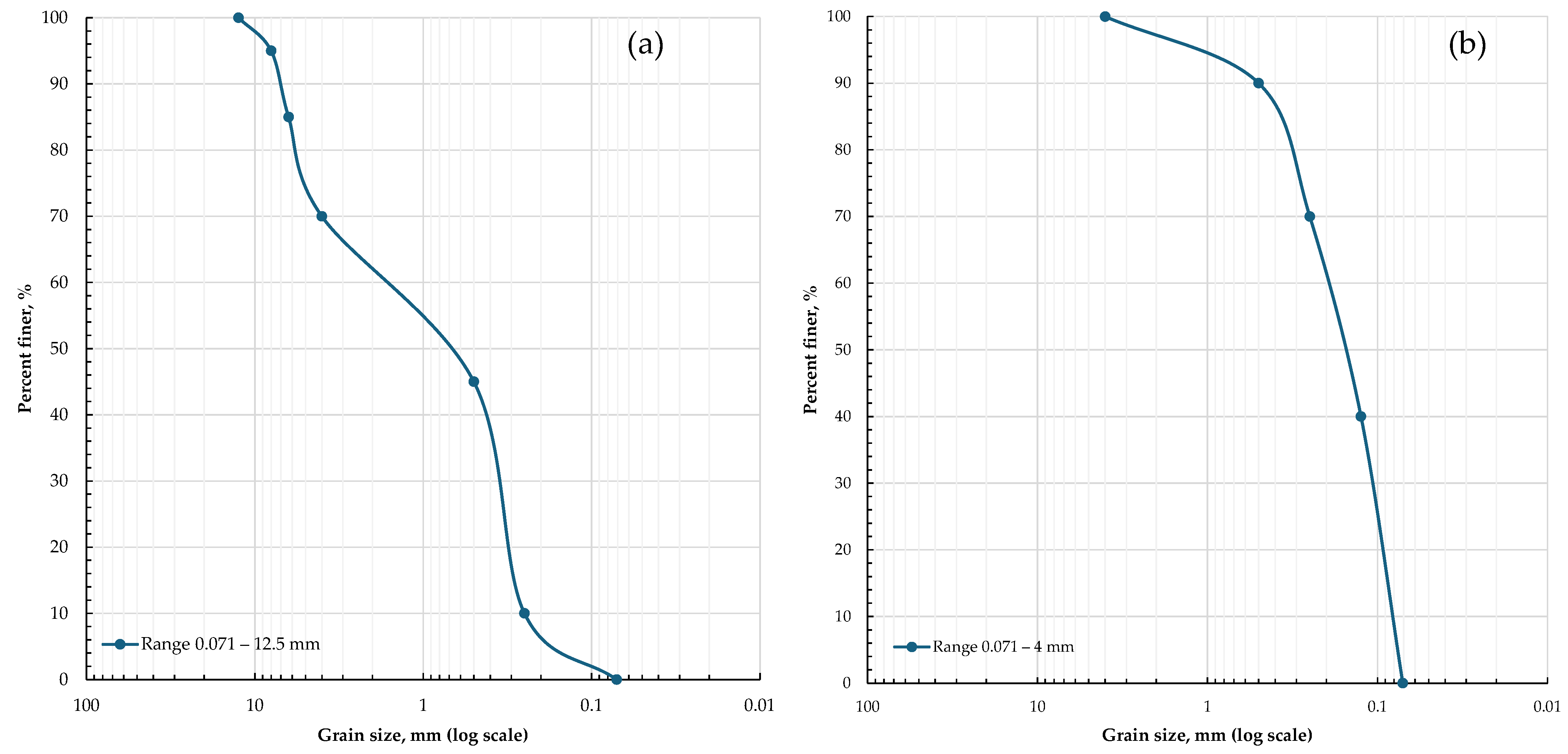
Table 1, a larger particle size distribution range of up to 12 mm was initially taken into consideration. This combination, which has a fractal dimension of roughly 2.9, was the first batch of tests that were successful.
Because the permeability of the fault gouge zone, especially in caprocks of CO
2 storage sites, is desirable to be relatively smaller, we aimed to maintain finer particles. Therefore, the next batch of tests was conducted on the next composition with a higher share of finer particles, and larger particles were eliminated (
Table 2). Similarly, in the research conducted by Storti et al. (2003), titled “Particle size distributions in natural carbonate fault rocks: insights for non-self-similar cataclasis”, a particle size range from 125 microns to 4 mm was studied as well [
17].
Consequently, the table above displays the size distribution ranges of the considered sieve meshes, as well as those available in our laboratory settings and closer to the ones reported in the literature.
2.2. Experimental Setup
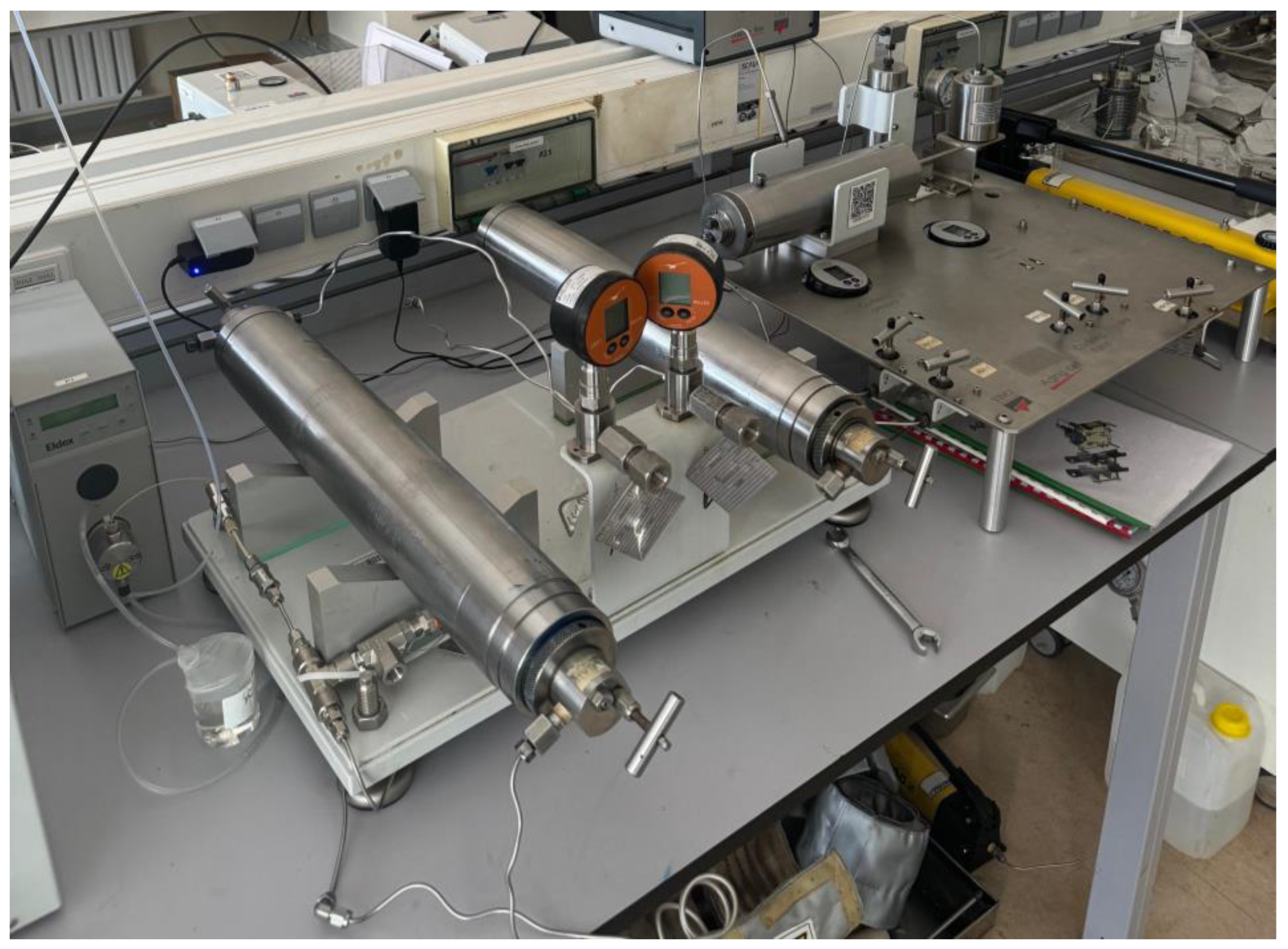
The experimental program was conducted using the School of Mining and Geosciences (SMG) core-flooding system, where confining pressure was varied while other parameters, such as the flow rate, fault gouge material composition, and outlet pressure, remained constant. It is therefore possible to evaluate the permeability of the fault gouge material under different conditions by using this experimental approach. The tests were carried out with varying flow rates of up to 1.5 cc/min and fixed confining pressures of 500 psi, 1000 psi, and 1500 psi. Initially, the confining pressure was elevated and set to the following values of 500 psi, 1000 psi, and 1500 psi, but then during the experiments, there were some pressure releases from the system, and the confining pressure loss was not that significant; it was within ±10% of the experiment’s starting value. The proposed methods are intended to be implemented with the use of the above-mentioned compositions. We will vary the composition of the fault gouge material in our upcoming research to correlate confining pressure and permeability with composition variations in a minor step, even though we only looked at two compositions in this work. This rigorous method aims to provide credible insights into the behavior of fault gouge material under conditions like those seen in actual storage sites.
The Core-Flooding System (Aging Cell System), as shown in
Figure 1, was utilized to investigate the effect of the parameters listed, on the properties of the fault gouge material.
The fault gouge material samples were prepared using a deliberate and thorough set of techniques and trials. A sieve analysis was performed to separate the particles according to size. The samples were prepared in the Mineral-Processing Laboratory using its sieving facility. Particles of different sizes were then mixed to achieve the desired compositions depicted in
Figure 2.
Then, to facilitate the molding of the sample, a small quantity of water was added to the mixture. Subsequently, the mixture was poured into a plastic mold and consolidated inside a steel tube using a three-ton hydraulic jack.
Figure 3 illustrates a view of the prepared sample before it was inserted into the core-flooding system. After that, the exterior surface of the consolidated sample was lubricated before being placed within the core holder. To stop fines migration out of the core-flooding system, the prepared screens were positioned on both ends of the samples.
Then, in order to replicate the subsurface conditions, the confinement pressure was raised. The goal was to replicate a particularly effective pressure in the lab, where the depth gradient is assessed at hypothetical storage locations that are relatively shallow and middle-deep and the lithostatic pressure is balanced with hydrostatic pressure. Tests were conducted at specific flow rates, and the pressure differential was recorded. To preserve laminar flow, the flow rate was kept at comparatively lower levels, and the Darcy law was used to estimate the water injection that was applied at this point. Darcy’s Law was employed as illustrated below to determine the permeability of the fault gouge sample.
where
k is the permeability,
q is the flow rate,
is the fluid viscosity,
L is the length of the sample,
A is the cross-sectional area of the sample, and
is the pressure difference across the sample.
The experimental setup presented here was intended to evaluate the impact of confining pressure on the permeability evaluation of fault rock material in a laboratory setting under carefully controlled conditions. To understand how such changes might affect permeability, we intend to change the fault gouge’s composition in subsequent experiments by, for example, altering the amount of clay content, but not for the current research. Only two fault gouge compositions with varying size distribution ranges were investigated in this study, but the impact on coarser and finer fault gouge compositions is discernible.
3. Results
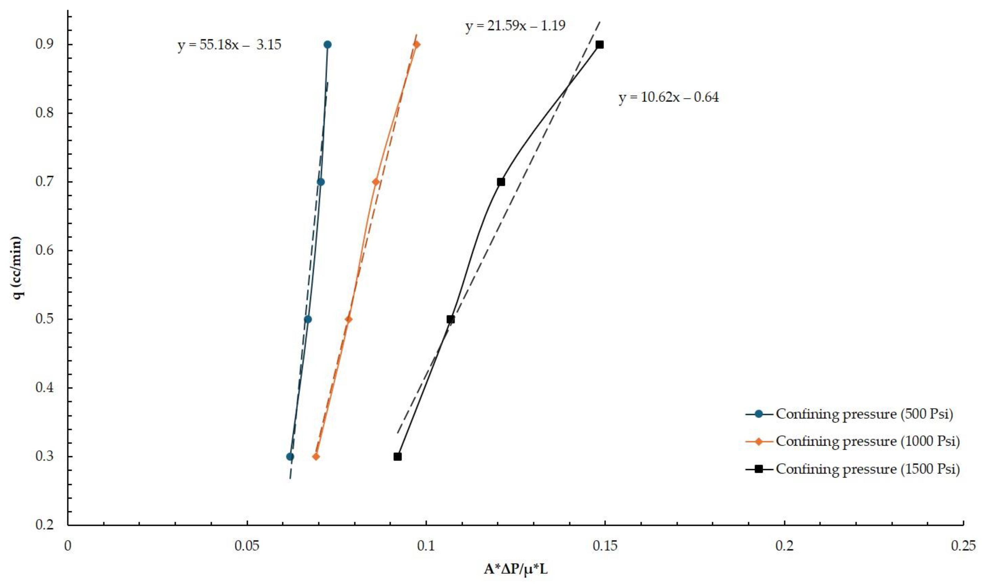
Figure 4 and
Figure 5 illustrate the data obtained from these experiments. The permeability coefficient can be determined as a tangent of the plot, with the
Y-axis representing the injection flow rate and the
X-axis representing (A∙∆P)/(μ∙L). The vertical
Y-axis shows the injection flow rate, while the
X-axis displays an application of the Darcy Law (Equation (4) is rearranged into Equation (5)).
The obtained results enable us to compare the obtained permeability coefficient at different confining pressures. Permeability and confining pressure are clearly linked at all flow rates, with permeability decreasing as confining pressure rises. The dashed lines correspond to the linear trendline for each set of confining pressure measurements. For example, a permeability of 55.2 md was measured for the first set of fault gouge material samples at a 500 psi confining pressure. By increasing the confining pressure to 1000 psi, which is double the increase, the permeability fell by about 2.6 times to 21.6 md. In general, permeability dropped as the confining pressure increased. Interestingly, permeability only declined twice, reaching 10.6 md, when the confining pressure increased from 1000 psi to 1500 psi.
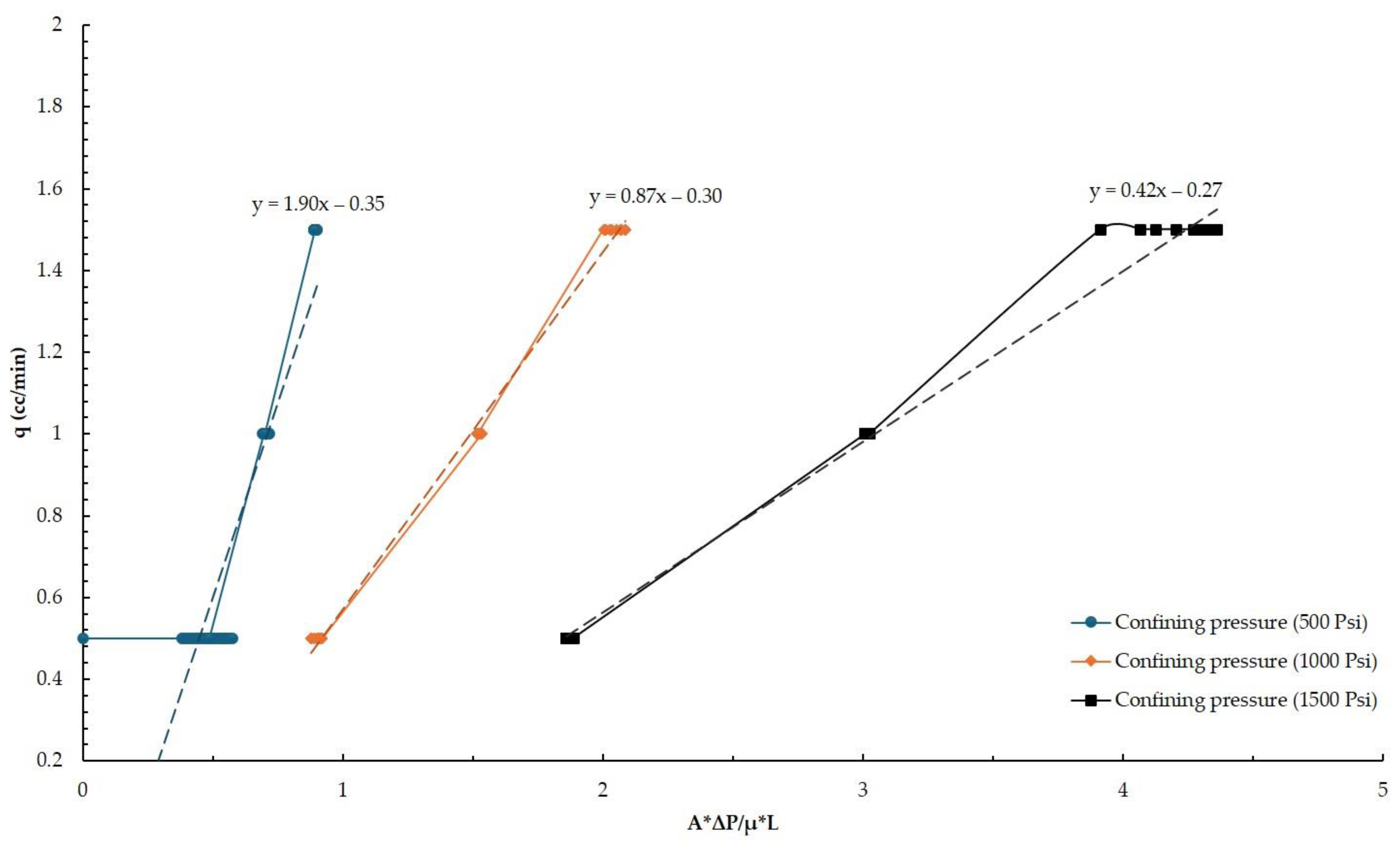
As shown in
Figure 5, the trend of decreasing permeability with increasing pressure confining was once more confirmed for the second set of experiments. The measured permeabilities under 500 psi, 1000 psi, and 1500 psi are 1.90 md, 0.87 md, and 0.42 md, respectively, as compared to the first set of experiments.
The permeability coefficient decreased from 1.90 to 0.87 md, or roughly 2.2 times, when the confining pressure was increased from 500 psi to 1000 psi. When the confining pressure was increased from 1000 psi to 1500 psi, the permeability coefficient decreased to nearly twice as much as the first compositional set of fault gouge samples that were tested in the first experimental sets. According to the obtained results, a reduction in pore space and a corresponding drop in permeability occur as the confining pressure increases.
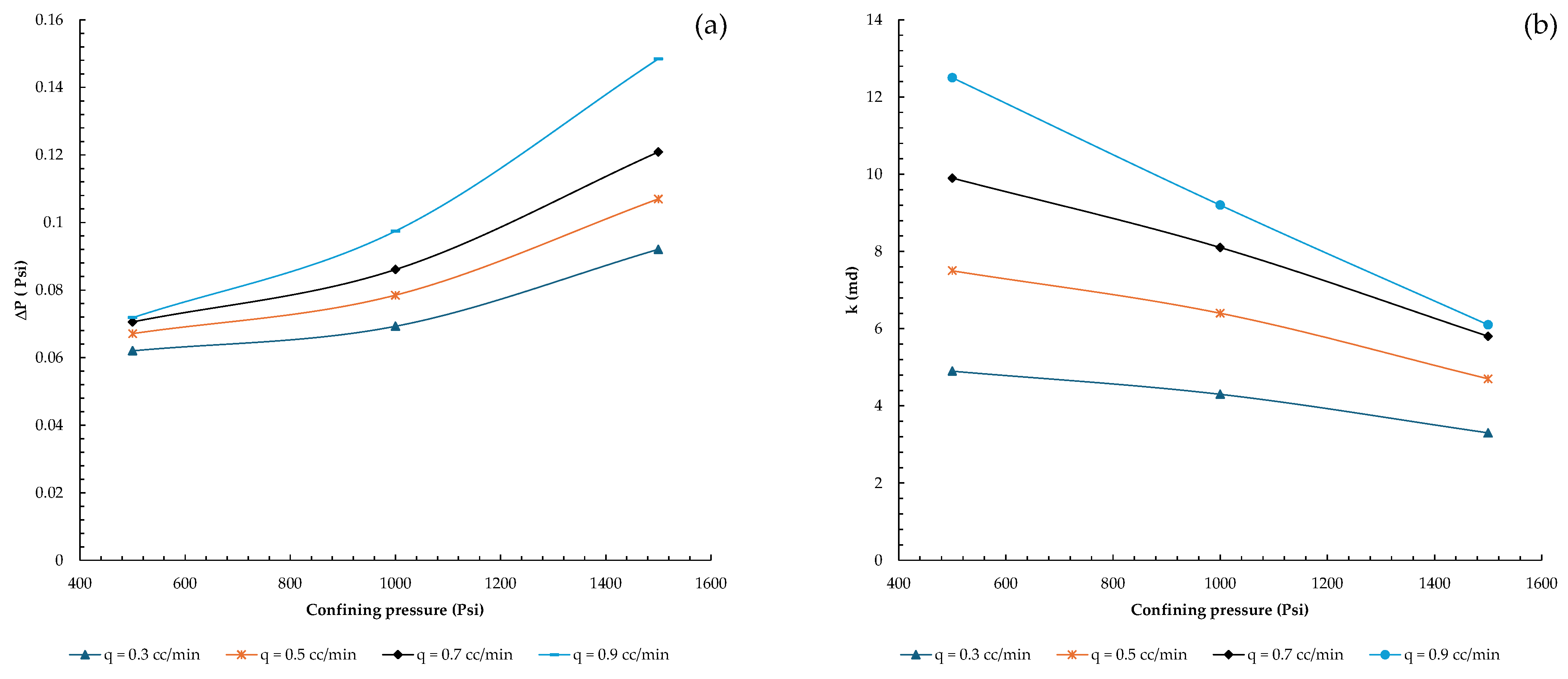
Interestingly, as illustrated in
Figure 6 and
Figure 7, the determined data also show that permeability varies for different flow rates at a fixed sample composition and confining pressure. This could be caused by particle migration and changes in the pore structure.
The observed pattern is likely seen in less consolidated samples, indicating that the selected specimen is consistent with a deformable medium with possible particle rearrangements with an interacting flow rate and stress. When examining
Figure 6a at lower confining pressure values, the impact of varying injection flow rates is significantly greater than at higher confining pressures, where the effect of injection flow rates on permeability fluctuation becomes less sensitive.
All the recordings for the samples are shown in
Figure 4 and
Figure 5, and permeability calculations were performed using the best-fit line that was found. In core-flooding studies, this is the standard process for determining the permeability of the core samples. The stabilized pressure readings serve as the basis for the data shown in
Figure 6 and
Figure 7. Only stable pressure differences and specific injection velocities are shown in these figures.
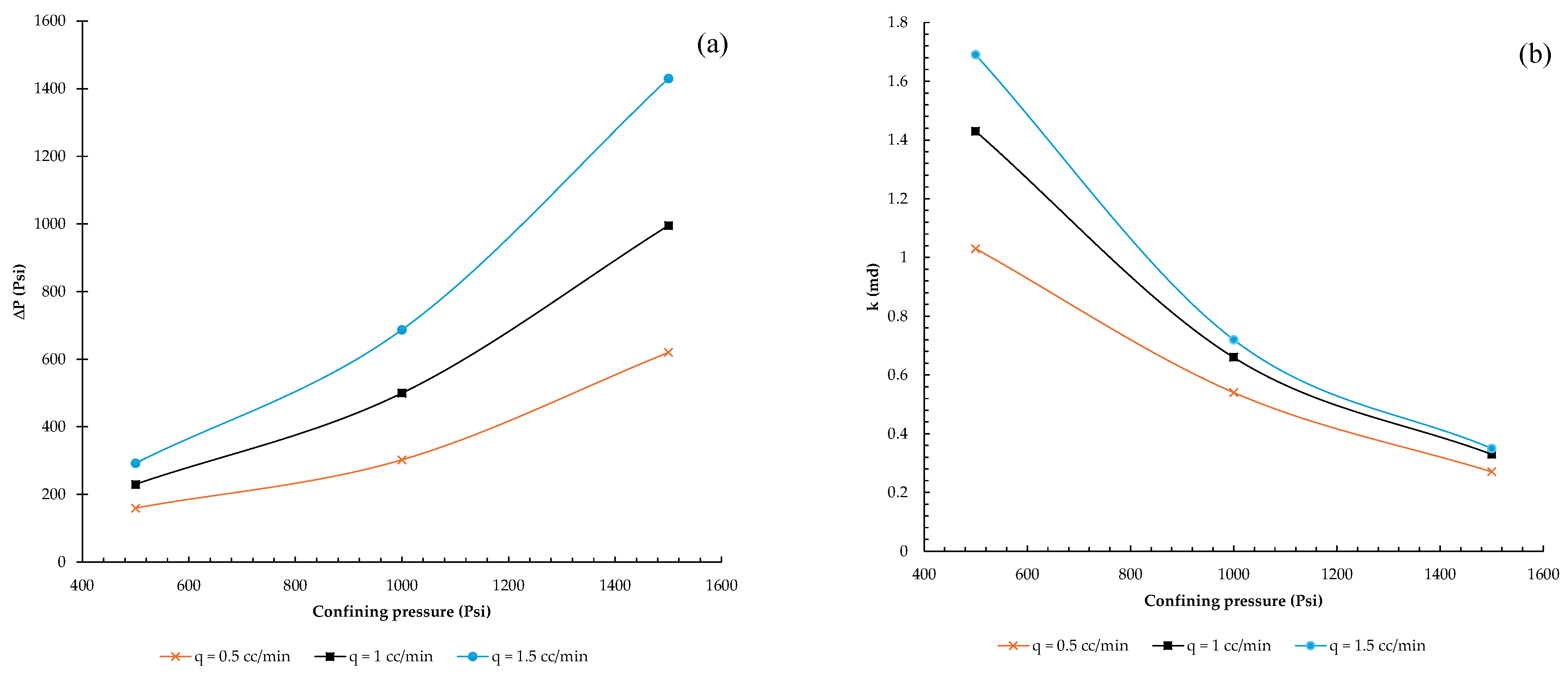
As shown in
Figure 7, the second set of fault gouge samples exhibited similar behavior, with permeability variation becoming insignificant under elevated confining pressures determined at 1500 psi. At first, it was thought that the sample’s permeability should not be considerably altered by changes in flow rate. The injection flow rates in the first set of fault gouge samples ranged from 0.3 to 0.9 cc/min at intervals of 0.2 cc/min. When the effluent was studied following the trials at various confining pressure levels and flow rates, the fault gouge composition remained constant and comparatively stable with no fine migration towards the outlet. Therefore, the injection flow rate intervals were raised to 0.5 cc/min and adjusted from 0.5 cc/min to 1.5 cc/min to observe the influence of the flow rate in the second set of tests (second batch of fault gouge samples).
4. Discussions
The results from the conducted experiments, employing a core-flooding system, are satisfactory and in line with the literature, in which an increased compaction rate with an elevation of effective pressure in laboratory conditions leads to a reduction in the permeability of the fault gouge samples. Specifically, different studies have documented a decrease in permeability in fault gouge samples under incrementally increased effective pressure from 5 MPa to 50 MPa, especially in clay-rich samples that may experience several orders of permeability reduction. Nonetheless, the fault gouges with non-clay compositions show that permeability decreases as the compaction increases, though not as drastically as observed with clay particles, according to Crawford et al. [
18].
Similarly, the permeability of the fault gouge sample was reduced as the confining pressure increased for both sets of fault gouge compositions, based on the data obtained. Field and laboratory observations also corroborate the concept that the confining pressure usually leads to less pore space and less permeability, as demonstrated by the obtained experimental data [
19]. As anticipated, these outcomes are in conformity with other studies where compaction and microstructural changes play a key role in drops in permeability in fault gouges. For instance, normal stress has a positive impact, leading to grain breakages that minimize pore spaces and enhance fault frictional strength, which is similar to declining permeability under high-stress states [
20].
Another interesting characteristic seen in the tested fault gouge samples is that the permeability coefficient varies in response to changes in the fluid’s injection velocity. This is a distinct and original discovery from the experiments that were carried out.
The traditional approach for manually recording the core sample’s permeability involves taking note of the pressure differential at various injection velocities. The average permeability value is then obtained from the trend line connecting these data points. The data shown in
Figure 4 and
Figure 5 are presented using this method.
In this study, however, as can be observed from the results presented here, the trend line differs from the stabilized pressure difference at each injection fluid flow, as illustrated in
Figure 5 and
Figure 6. Consequently, these values of estimated permeability for each velocity are presented separately in these figures. The current work’s results are corroborated by other research that also suggested that the potential for capillary and viscous effects was the reason why permeability estimations varied across different flow rates. It follows that the accuracy of permeability estimation itself and the core-flooding experiments depend on the correlation between permeability and injection flow rates [
21].
It is possible to deduce from the studies that were carried out that at greater injection velocities, particle migration and structural alteration of the pore structure may become important based on the differences in permeability shown in
Figure 6 and
Figure 7. However, the effect of injection velocity variation is acknowledged to be less significant at higher confining pressures, such as 1500 psi, than at 1000 psi and 500 psi, as often stated in the literature. In the first set of fault gouge compositions, for instance, compared to the second, permeability values decreased as the sample degree of consolidation increased, the percentage of finer particles increased, and the size distribution became more uniform with no notable outliers for larger particles.
Two sets of fault gouges have comparable mineralogic compositions overall but their size distributions differ. The first one’s particle mean size is 1.77 mm, with a larger size distribution that reaches up to 12 mm from roughly 0.071 mm. Comparatively speaking, the second group of samples has a maximum particle size of 4 mm and a mean particle diameter of 0.17 mm, which is 10 times smaller than the first set.
As is well known, defects may affect the integrity of the caprock and sealing capacity. When comparing the two sets of experiments, the first fault gauge composition may not be a good choice due to the possibility of high leakage risks, but the second fault gauge composition may be a relatively better sealing barrier because of its permeability of less than 1 md.
Research on natural fault gouges taken from active fault zones, however, shows somewhat lower permeability values based on field data. For example, at effective confining pressures of up to 120 MPa, the permeabilities observed on the core samples taken from the actively deforming zones at the San Andreas Fault Observatory at Depth (SAFOD) were 10
−21 to 10
−22 m
2 (about 1 to 0.1 nano Darcy). These numbers are far less than the about 1 md that was seen in the experiments [
22]. Therefore, the tested artificial fault gouge material behaves similarly to fault gouges at shallower CO
2 storage site depths with lower clay content since the permeability from the conducted studies is higher than from active fault zones.
The observed variations in permeability with flow rate highlight a key factor: the flow rate has a much more profound influence on pore structure and permeability in, for example, less consolidated porous media. This finding is particularly important for predicting the behavior of fault gouge material under conditions of CO2 injection where the presence of higher flow rates is likely to enhance the propensity of particle transport and possible clogging within the fault gouge domain.
5. Conclusions
The results of this research add some new insights into fault gouge permeability as it demonstrates the pressure and flow rate influence on the gouge permeability coefficient based on the experimental study. The information obtained from the results can be used in assessing fault integrity, which is essential for reducing the likelihood of leaks in real CO2 storage projects.
The outcomes of this work indicate that the permeability of simulated fault gouge material decreases as the confining pressure rises, which is in agreement with the observations in the literature [
18,
19,
20]. It was also observed that the permeability changed with an increasing flow rate, speculated to result from changes either in pore structure or particle migration, mainly in the less consolidated samples.
The study’s artificial fault gouge material effectively replicated the behavior of natural fault gouge in subsurface circumstances, according to the results obtained. By applying higher confining pressures, predictions can be made at greater depths, which makes the data useful for modeling CO2 storage in deeper fault zones.
Our future work will involve changing the composition of the fault gouge material to study the interaction of mineralogy and confining pressure on permeability. Also, injection of the supercritical CO2 is intended to be conducted in the continuation of this work. Such an approach would be useful in enhancing our knowledge of the behavior of fault zones and assist in developing risk-mitigation measures for leakage in the locations intended for CO2 sequestration.


