Article

Design and Characteristic Research on Variable Displacement Mechanism of Two-Dimensional (2D) Bivariable Pump

Key Laboratory of Special Purpose Equipment and Advanced Manufacturing Technology, Zhejiang University of Technology, Ministry of Education & Zhejiang Province, Hangzhou 310014, China
*
Author to whom correspondence should be addressed.
Energies 2024, 17(7), 1725; https://doi.org/10.3390/en17071725
Submission received: 28 February 2024 / Revised: 21 March 2024 / Accepted: 27 March 2024 / Published: 3 April 2024

Abstract

:
In a hydraulic system, a micro variable pump is required to be high pressure and high speed, and this work presents a new type of 2D bivariable pump structure in which the worm gear and worm mechanism are used to rotate the cylinder block to change the flow distribution state of the cylinder window and the piston groove to change the displacement of the 2D pump. The flow–pressure mathematical model of the 2D variable pump is established to analyze the relationship between pump displacement and the pump cylinder rotation angle and the effects of variable displacement on pump pressure characteristics, flow characteristics, and volume efficiency in Matlab. During the experiment, we tested the change in the corresponding pump output flow when the cylinder rotation angle is 0~12°, which verifies the correctness of the variable calculation model. The experimental results indicate that the volume efficiency and mechanical efficiency of the single-piston 2D pump are reduced to different degrees after variable displacement, the volume efficiency is reduced by approximately 3% at most, and the mechanical efficiency is reduced by approximately 5% at most.

1. Introduction

With the development trend of high pressure, high power, variable pressure, and intelligence of hydraulic systems in aerospace, robotics, construction machinery, and other fields, the distributed hydraulic control system will be widely used in the future [1,2,3]. In the aviation field, the new EHA (Electro-hydrostatic actuator) has been used to replace the traditional hydraulic actuator in the airborne hydraulic actuator system [4,5,6,7]. As an important part of EHA, a micro bivariable electric pump that can meet the requirements of high speed, wide speed range, and high pressure has always been a research hotspot in the current hydraulic field [8,9]. The current electric pumps used in EHA are exclusively swash plate axial piston pumps [10,11].
The high-speed bivariable swash plate axial piston pump has been extensively researched both domestically and internationally, with foreign research leading the way. At present, the high-speed EHA pump has found application in the F-35 flight control drive system, providing power for its primary and secondary flight control surfaces [12,13]. Park Hannifin, Eaton Aerospace, and other suppliers provide Airbus and Boeing with high-performance and high-speed aviation plunger pumps [14]. The average speed is more than 3500 r/min, and some EHA pumps can even reach 22,500 r/min and the operating life can reach more than 20,000 h [15]. Vacca et al. from Purdue University used the virtual prototype method to design the surface texture of the micro-surface contour of the piston–cylinder interface of the piston pump and studied the influence of the contour shape on the load under the high-pressure condition and concluded that the concave hole contour could best improve the overall load support under the high-pressure stroke [16]. Domestic research on the high speed of the bivariate axial piston pump is mainly carried out in colleges and universities. Wang et al. from Beijing University of Aeronautics and Astronautics proposed a fatigue analysis and life prediction method for a cylinder block of an aviation piston pump and carried out experiments in the working pressure range of 28–52 MPa and the speed range of 3000–7800 r/min, which provided a reference for the design of a compact piston pump cylinder block [17]. Chao and Zhang et al. from Zhejiang University proposed a new integrated slipper holding mechanism suitable for a high-speed axial piston pump, which can eliminate slipper wear under harsh working conditions, and carried out experimental verification on a high-speed pump of 10,000 r/min [18]. Ou Yang Xiaoping et al. initiated the three-stage pressure structure and control technology of a constant-pressure variable aviation piston pump, proposed the damping optimization method of a variable regulation mechanism, and realized the stable switching of (28/21/6) MPa three-stage pressure so that the working efficiency of the pump in the system increased by more than 25% and the life increased by more than 50% [19].
Research on the swash plate piston pump has been carried out for many years, and the technology is relatively mature. However, there are still some problems under high-speed conditions, such as the overturning force of rotating components causing serious bearing friction and wear, resulting in a rapid reduction in efficiency and short life. In recent years, the two-dimensional (2D) piston pump has been more suitable for high-speed motorization applications due to its axis symmetric structure and rolling friction pair. The team of Prof. Ruan Jian from Zhejiang University of Technology has designed a variety of 2D pumps with various structures. Among them, Li et al. designed and studied a micro 2D pump with a double-cam rotation type with a maximum speed of 12,000 r/min, output pressure of up to 21 MPa, and output flow of 18 L/min [20,21]. Wu et al. designed and studied a 2D pump with a fixed cam and rotary roller frame, which produced less vibration and noise during operation. Furthermore, this design showcases slightly improved volumetric efficiency and mechanical efficiency compared to the double-cam rotating type [22]. Furthermore, Huang et al. designed and studied 2D piston pumps with a balanced force, in which two pairs of cams drive the piston and the cylinder, respectively, and the inertia forces of the cam–cylinder assembly and cam–piston assembly in relative motion cancel each other, thereby reducing the vibration of the pump [23]. Jin et al. designed and studied a 2D tandem pump, which eliminated flow pulsation by connecting two 2D piston units at a misaligned 45° angle [24]. Wang et al. designed and studied the 2D pump with a stacked cone roller set. The load capacity of the pump can be greatly improved by the overlapping mutual support of the cone roller set, and the gap between the roller and the cam can be effectively compensated by the liquid pressure at the bottom of the cone roller, so as to improve the life and reduce the noise [25]. In the study of a 2D pump, the author found that when the piston moves to the limit position, the displacement of the pump will be reduced if the distribution port by the cylinder window and the piston groove is opened rather than closed, and the degree of reduction is related to the opening amount of the distribution port at this time. According to this phenomenon, this paper tries to design a 2D pump with variable displacement and designs the cylinder rotation control mechanism to realize the opening amount change in the distribution port formed by the piston and the cylinder when the limit position of the piston is changed. This paper will analyze the principle of variable displacement and study the characteristics of the pump after variable displacement.

2. Mechanism and Working Principle

Figure 1 shows our proposed design concept of the bivariate 2D pump structure diagram. In the right pump body is a two-dimensional piston drive assembly, and in the left pump body is a distribution assembly and a variable displacement assembly. The driving assembly is mainly composed of two saddle-shaped cam guides and four cone rollers. The motion law of the cams is equal acceleration and deceleration. The two cams are fixed on the piston shaft to drive the piston to rotate and reciprocate. The distribution assembly is composed of a piston with two pairs of flow distribution slots and a cylinder block with four rectangular windows. The piston, the cylinder block, and the sealing ring form two closed working cavities, and the two pairs of flow distribution slots on the piston communicate alternately with the two working cavities. The variable displacement assembly is composed of a worm gear, worm, stepper motor, and cylinder body. The worm gear and the cylinder body are fixed and rotate synchronously by connecting pins.
When in operation, the speed-regulating motor drives the cam-piston motion assembly through the coupling to achieve rotational and reciprocating motion. The piston moves reciprocally according to the law of equal acceleration and deceleration, completing one rotation and four reciprocating movements. This enables alternating communication between the two piston cavities and the suction/discharge ports through the piston distribution groove, resulting in each working cavity performing two cycles of oil suction and discharge.
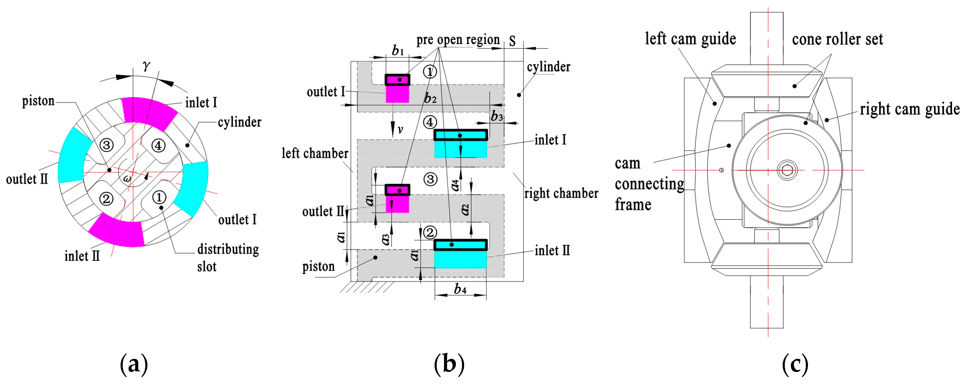
The Working Principle of 2D bivariable pump is shown in Figure 2. Figure 2a shows the distribution section diagram of the piston–cylinder section when the piston is in the left limit position. Figure 2b shows the circumferential expansion diagram of the piston–cylinder block; as shown in the figure, the opening amount of the distribution port is referred to as the pre-open region. Figure 2c is a schematic diagram of the driving mechanism. When the displacement needs to be changed, the stepper motor drives the worm to rotate, and the cylinder connected to the worm wheel also has a corresponding rotation angle γ, which is called the cylinder rotation angle. After cylinder rotation, with the change in piston angle, the relationship between the communication state of the distribution window and the reciprocating movement phase of the piston changes. Figure 2 shows the state of the piston at the end of the left working stroke. At this time, the flow distribution window is open, indicating that the piston will be sucked into the right chamber from the discharge outlet and discharge oil to the suction port before the end of the left working stroke, thus reducing the displacement.
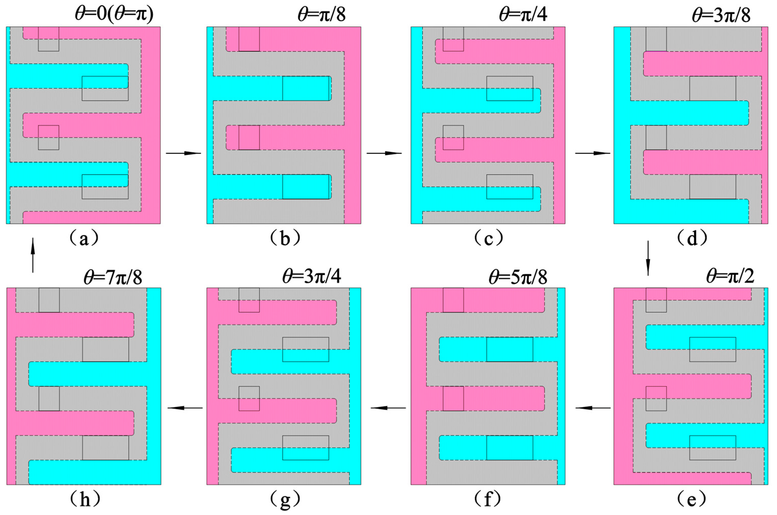
Figure 3 shows the schematic diagram of the pump flow distribution process after the cylinder block rotates one cylinder block angle. We can assume that the piston groove and the cylinder block distribution window form an angle γ of π/8. As shown in Figure 3a, the piston is in the left limit position. Due to the angle of the cylinder block, the suction inlet and the discharge outlet are opened, and the oil in the left chamber communicates with the suction port, while the oil in the right chamber communicates with the pressure port. As shown in Figure 3b–d, the piston moves to the right, the left cavity is sucked in, and the right cavity is discharged. As shown in Figure 3e, the piston is in the right limit position. Before the piston reaches the right limit position, due to the existence of the Angle of the cylinder block, the two distribution ports are opened again, and the oil in the right chamber is discharged from the suction port and the oil in the left chamber is inhaled from the discharge outlet. As shown in Figure 3f–h, the piston moves to the left, the left cavity is discharged, and the right cavity is inhaled. When the piston moves again to the position in Figure 3a, the piston completes a suction and discharge working cycle, and the left and right cavities suck once each.

3. Mathematical Model

To study the variable displacement characteristics of the 2D pump, this paper established the flow-pressure differential equation of the pump with the cylinder rotation angle according to the literature “Hydrostatic Pumps and Motors: Principles, Design, Performance, Modelling, Analysis, Control and Testing” [26], so as to analyze the change law of pressure and flow in the piston working chamber and analyze the volumetric efficiency of the pump.
d p 1 = β e d t V q + q c + d V d t
Due to the left and right oil chambers of the 2D bivariable pump working in the same way, the pressure and flow characteristics of the left chamber of the piston are modeled below. The pressure change in the left chamber can be expressed by Equation (1): Due to the cam guide adopting the motion law of equal acceleration and deceleration, the stroke generated by the piston is h, and the formula of the acceleration a of the piston can be expressed as follows:
a = h × 2 n 15 2
We assume that when the pump piston is in the left limit position at startup, the running time of one stroke is t. The cylinder block Angle γ does not affect the reciprocating movement time of the piston but changes the flow timing of the distribution window, and the instantaneous volume expression in a suction and discharge period of the left chamber of the pump can be expressed as follows:
V = V min + π D 2 d 2 a 2 t 60 γ 360 n 2 , t 0 + 30 k n , 15 2 n + 30 k n V min + π D 2 d 2 h π D 2 d 2 a 2 t 15 n 60 γ 360 n 2 , t 15 2 n + 30 k n , 45 2 n + 30 k n V min + π D 2 d 2 a 2 t 30 n 60 γ 360 n 2 , t 45 2 n + 30 k n , 30 k + 1 n k = 0 , 1 , 2 , 3
We take the derivative of Equation (3) to find the piston volume change rate dV:
d V = π D 2 d 2 a t 60 γ 360 n d t , t 0 + 30 k n , 15 2 n + 30 k n π D 2 d 2 a t 15 n 60 γ 360 n d t , t 15 2 n + 30 k n , 45 2 n + 30 k n π D 2 d 2 a t 30 n 60 γ 360 n d t , t 45 2 n + 30 k n , 30 k + 1 n
The change in the flow area of the distribution window is related to the cylinder rotation angle and the working time, which can be expressed as follows:
A = 2 π b 4 D t 60 γ 360 n 60 , t 0 + 30 k n , 15 2 n + 30 k n 2 π b 4 D 15 n t + 60 γ 360 n 60 , t 15 2 n + 30 k n , 15 n + 30 k n 0 , t = 15 n + 30 k n 2 π b 1 D t 60 γ 360 n 15 n 60 , t 15 n + 30 k n , 45 2 n + 30 k n 2 π b 1 D 30 n t + 60 γ 360 n 60 , t 45 2 n + 30 k n , 30 k + 1 n 0 , t = 30 k + 1 n
The suction or discharge flow of the left cavity is calculated according to the thin-walled orifice throttling equation, which can be expressed as follows:
q = C d A 2 p i n p 1 ρ , t 0 + 30 k n , 15 n + 30 k n 0 , t = 15 n + 30 k n C d A 2 p 1 p o u t ρ , t 15 n + 30 k n , 30 k + 1 n 0 , t = 30 k + 1 n
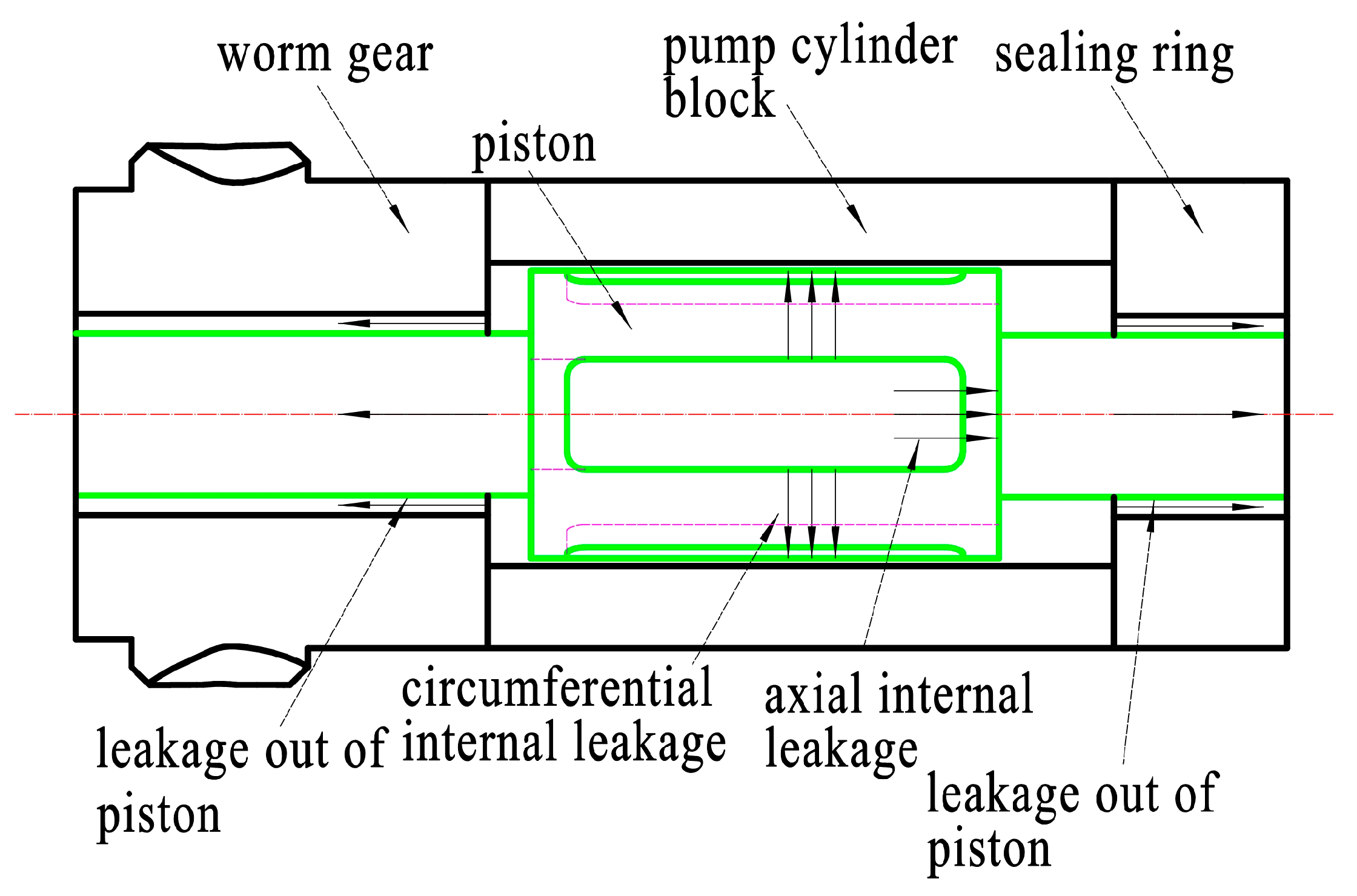
The leakage loss of the pump is shown in Figure 4. The leakage is composed of the leakage at the sealing ring and the axial and radial leakage at the piston distribution groove:
q c = q c 1 + q c 2 + q c 3
q c 1 is the leakage of oil from the high-pressure chamber through the gap of the concentric ring between the cylinder and the piston, and its expression can be referred to as the leakage formula of the hydraulic pump:
q c 1 = π d δ 3 12 μ ( l o s ) p 1 + π d δ 2 v
q c 2 is the piston axial internal leakage, that is, the axial leakage between the left and right cavities of the piston:
q c 2 = π D δ 3 12 μ b 3 p 2 p 1 π d δ 2 v
q c 3 is the circumferential internal leakage of the piston from the high-pressure groove of the piston to the low-pressure groove on both sides, which can be considered the sum of the gap leakage of constant length and the gap leakage of variable length:
q c 3 = B δ 3 12 μ a 2 ( p 1 ) + b 1 δ 3 12 μ a 3 ( p o u t p 2 ) + b 4 δ 3 12 μ a 4 ( p 1 p i n )
As shown in Figure 2b, the width of the flow distribution window is equal to the width of the flow distribution groove. Therefore, the width of the two variable seals is equal, which is expressed as follows:
a 3 = a 4 = 2 π n D 60 , t 0 + 30 k n , 15 2 n + 30 k n 2 π n D 60 ( 15 n t + 60 γ 360 n ) , t 15 2 n + 30 k n , 15 n + 30 k n 2 π n D 60 ( t 60 γ 360 n 15 n ) , t 15 n + 30 k n , 45 2 n + 30 k n 2 π n D 60 ( 30 n t + 60 γ 360 n ) , t 45 2 n + 30 k n , 30 k + 1 n
When the distribution window is close to closing, the piston circumferential leakage is the largest, which can be referred to as the leakage flow formula of the small hole gap flow. When analyzing, the larger value of the two formulas is taken as follows:
q c 3 = B δ 3 12 μ a 2 ( p 1 ) + b 1 δ 3 12 μ a 3 ( p o u t p 2 ) + b 4 δ 3 12 μ a 4 ( p 1 p i n )
When the variable sealing width is continuously reduced to the same leakage amount calculated by the two formulas, the variable sealing width is the minimum value at this time, and the leakage less than this width is ignored, the variable sealing width minimum a 4 m i n can be expressed by the following equation:
a 4 min = b 4 δ 3 p 1 p i n 12 μ C d b 4 δ 2 p 1 ρ
Finally, we obtain the overall leakage according to Equations (7)–(12) and obtain the flow-time function of the left cavity according to Equations (5) and (6). Then, we obtain the pressure time function of the left cavity according to Equations (1)–(4) and (7) and the flow-time function.
Then, we obtain the oil volume output by the pump during a reciprocating working cycle of the piston by integrating the flow time function, and then divide it with the pump suction flow rate to obtain the volumetric efficiency after changing the displacement, as shown in Equation (14):
η = 0 30 n q n h π 15 30 n 60 γ 360 n D 2 d 2
When calculating the efficiency, the cylinder rotation angle γ is in the range of −45° to 45°. In addition, because the working principle of the right cavity of the pump is the same as that of the left cavity, its mathematical modeling is similar to that of the left cavity, so it will not be described.

4. Matlab Simulation Analysis

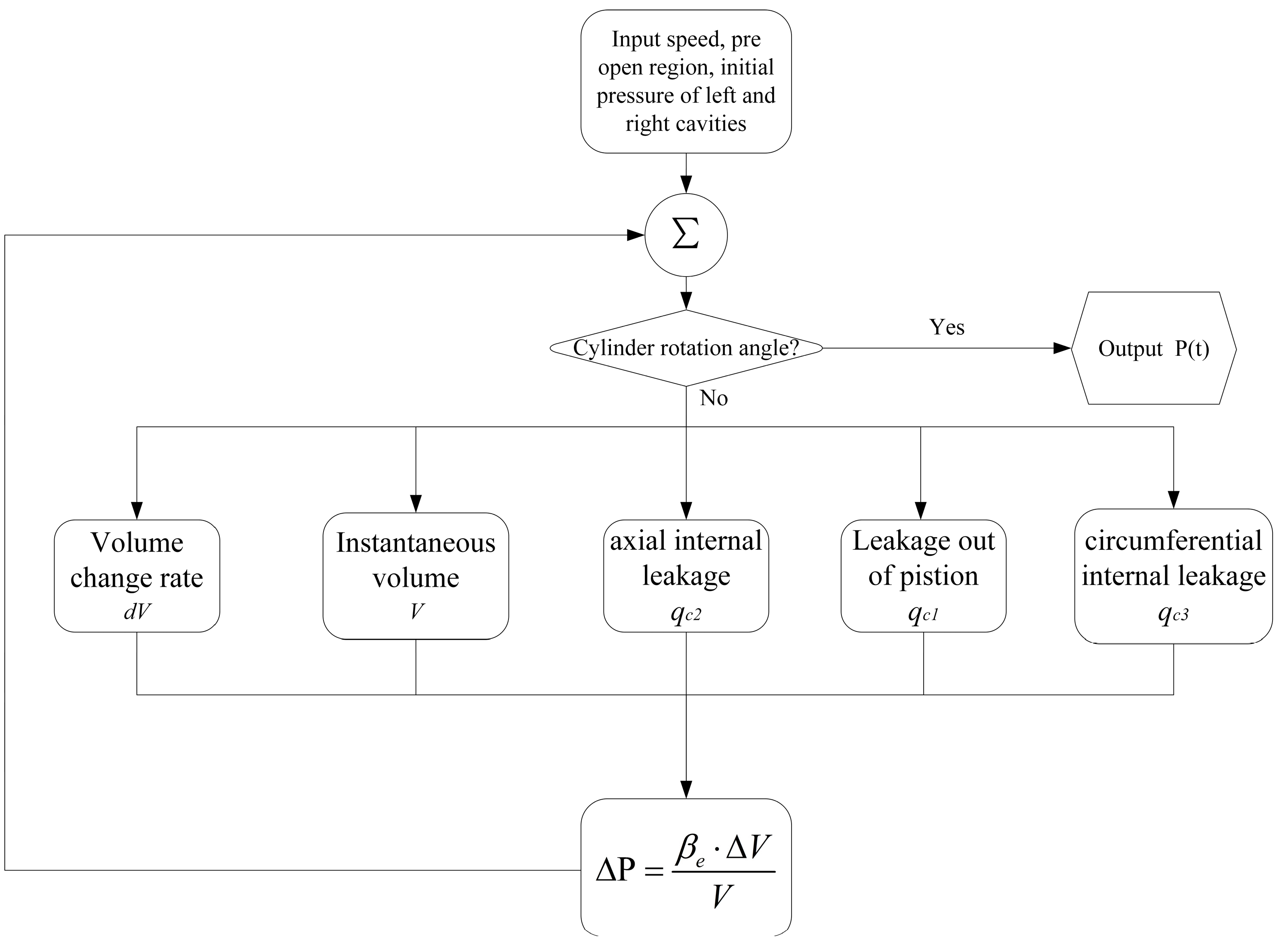
According to the pump press-flow equation and pump volumetric efficiency formula given above, the Matlab2021a simulation program is written, and the relationship between pump displacement and the cylinder rotation angle, the influence of the cylinder rotation angle on pump pressure characteristics, and the influence of the cylinder rotation angle on pump leakage are simulated and analyzed using the numerical analysis method. Figure 5 is the flow chart of the simulation program. The program takes time as the unit and converts time into the cylinder rotation angle, input speed, pre-open region, and initial pressure of left and right cavities, outputs the instantaneous volume, volume change rate, and leakage of left and right cavities, and analyzes the relationship between the cylinder rotation angle and pump displacement and flow leakage. We use the Runge–Kutta method to solve the press-flow equation and obtain the pressure change in the piston chamber as the relationship between the cylinder rotation angle and the piston chamber pressure. Table 1 shows the simulation parameters of the pump.
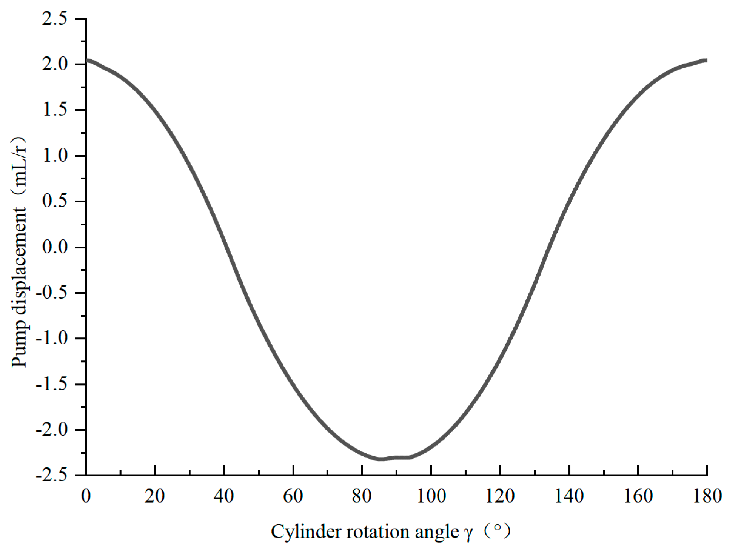
Figure 6 shows the relationship between the cylinder rotation angle and pump displacement of the pump. The displacement varies with the cylinder rotation angle according to a cosine law with a period of π. The pump displacement is the largest when the rotation angle is 0°, and the displacement is 0 when the rotation angle is 45°. If the rotation angle continues to increase, the pump displacement is negative, that is, the liquid flow direction changes, and the pump displacement is the largest when the rotation angle is 90°. The change law of pump displacement range when the angle is 90° to 180° is the same as that when the angle is 0° to 90°, according to the cosine law, from the maximum reverse displacement to the maximum forward displacement.
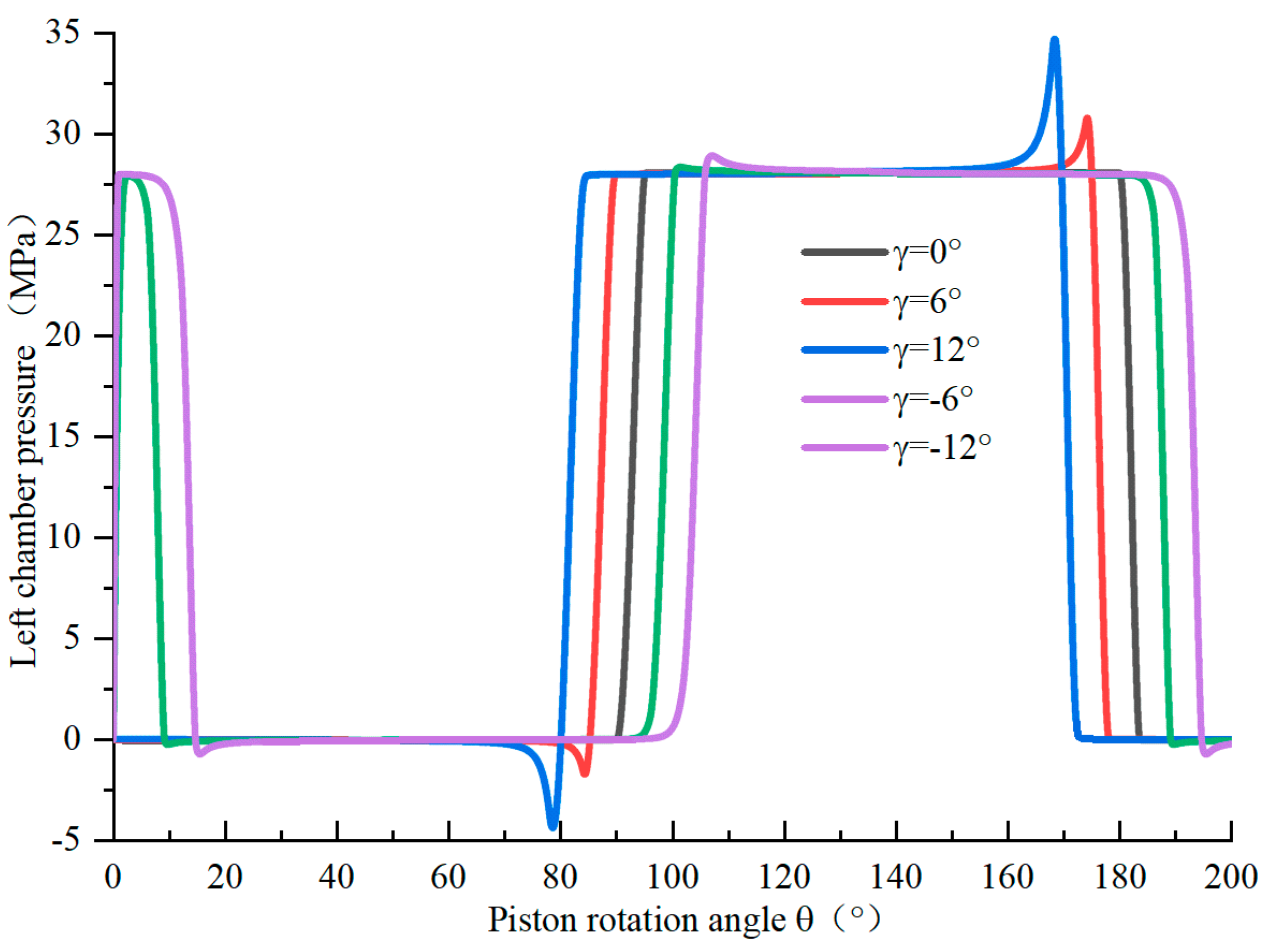
Figure 7 shows the relationship between the cylinder rotation angle and the pressure of the piston chamber for the pump. When the flow distribution window is opened, the pressure pulsation with the cylinder rotation angle is larger. The larger the rotation angle is, the greater the pressure pulsation is. The pulsation when the rotation angle is positive is greater than the negative one. The reason is that if there is a rotation angle, the piston is not in the limit position when the flow distribution window is opened, the velocity is greater than zero, and the instantaneous pressure pulsation in the cavity will be larger. If the cylinder rotation angle is positive and the piston rotation angle is zero, the left cavity of the piston communicates with the suction port. As shown in Figure 3, when the piston angle is 7π/8, the flow distribution window closes and the piston continues to move to the left, resulting in an instantaneous increase in the pressure in the chamber and large pressure pulsation. If the cylinder rotation angle is negative and the piston rotation angle is zero, the left cavity of the piston communicates with the pressure port. When the piston rotation Angle is 7π/8, the distribution window is closed and the piston continues to move to the left to reduce the pressure in the cavity, and then it does not produce pressure pulsation when communicating with the suction port.
As shown in Figure 8, if there is a cylinder rotation angle, the flow distribution window on the piston is open at this time, and the piston cavity generates additional leakage, causing the piston corner to have a large internal leakage around 0°. When the cylinder rotation angle is different, the angular position of the sudden change in the pressure in the cavity changes and the angular position of the sudden change in the leakage flow also changes accordingly, and the leakage when the rotation angle is negative is less than that when the rotation angle is positive.
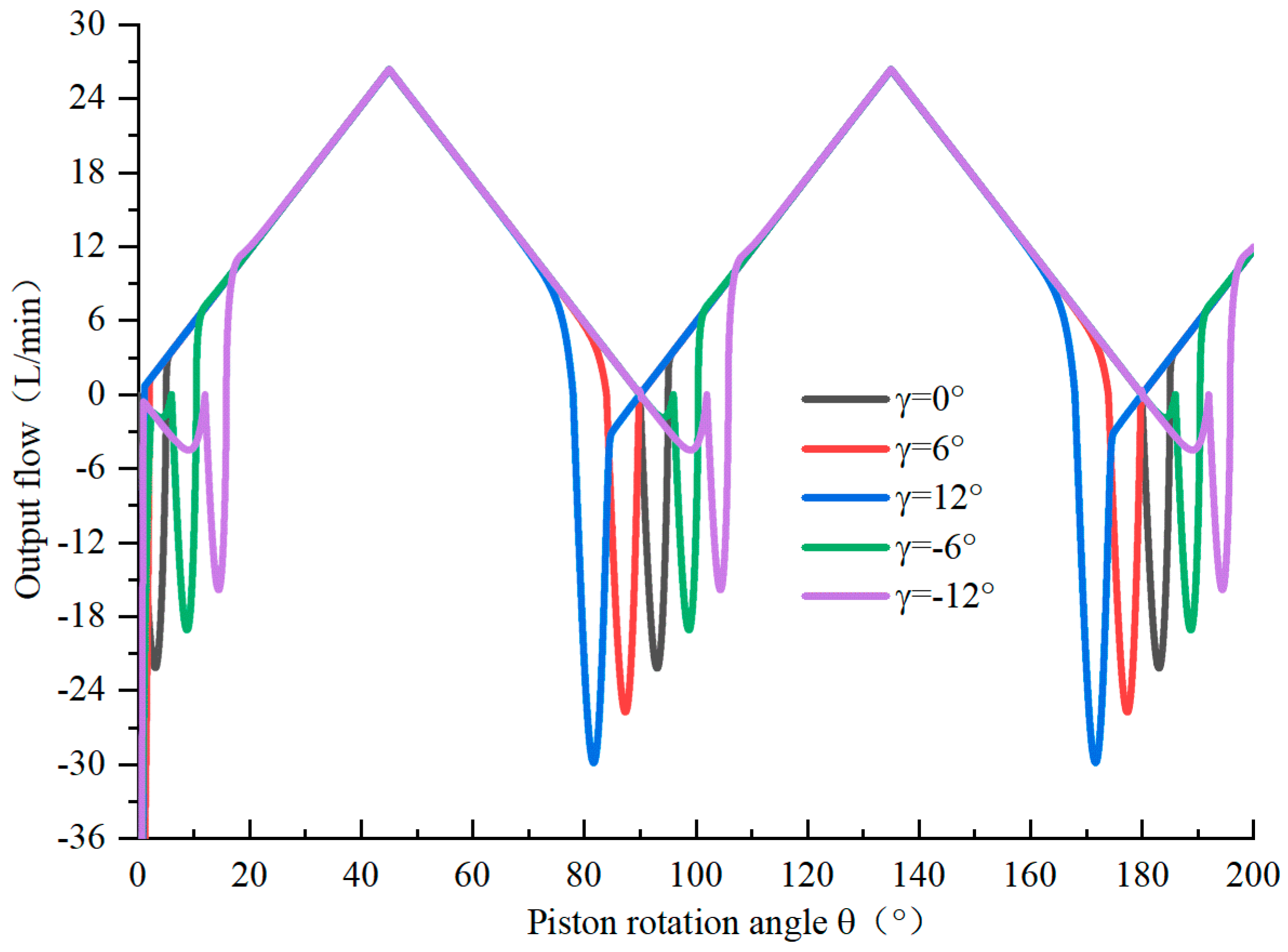
Figure 9 shows the output flow curve of the pump under different cylinder rotation angles. It can be seen from the figure that flow backflow occurs after the switch between the piston tank and the flow distribution window of the cylinder block and the reverse suction of oil from the outlet. The simulation results show that when the cylinder rotation angle is positive, the flow backflow of the piston is more serious, and when the cylinder rotation angle is negative, the piston cavity is communicated with the high-pressure oil port and the pressure difference is larger at this time, so the flow backflow is slightly better. In addition, it can be seen from the figure that because the piston cavity will communicate with the high-pressure oil port at the end of the oil suction action, part of the oil is inhaled from the high-pressure oil port so that when the cylinder body is negative, there is a flow fluctuation before the flow backflow occurs.
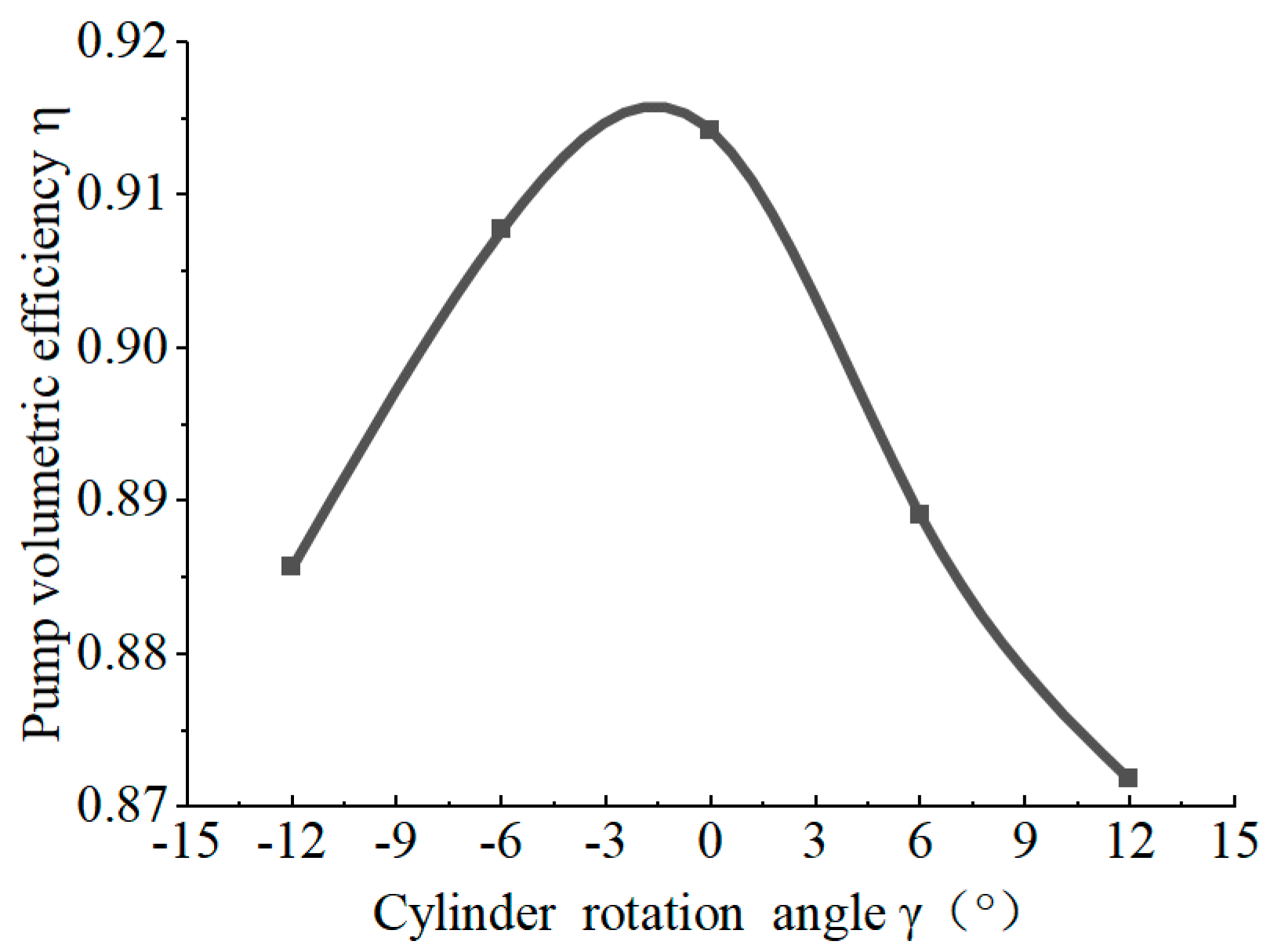
Figure 10 shows the changes in volumetric efficiency under different cylinder rotation angles. When the piston is in the limit position, turning the cylinder from the position of the closed piston distribution groove by an angle not only changes the displacement of the pump but also reduces the volumetric efficiency of the pump. When the displacement is 0, the volumetric efficiency also decreases to 0. The simulation results show that the volumetric efficiency of the cylinder block is reduced more when the cylinder block is in positive rotation, which is because the piston cavity communicates with the high-pressure oil port at the beginning of the oil absorption stage when the cylinder block is in negative rotation, which reduces the pressure in the cavity and reduces the leakage.

5. Test

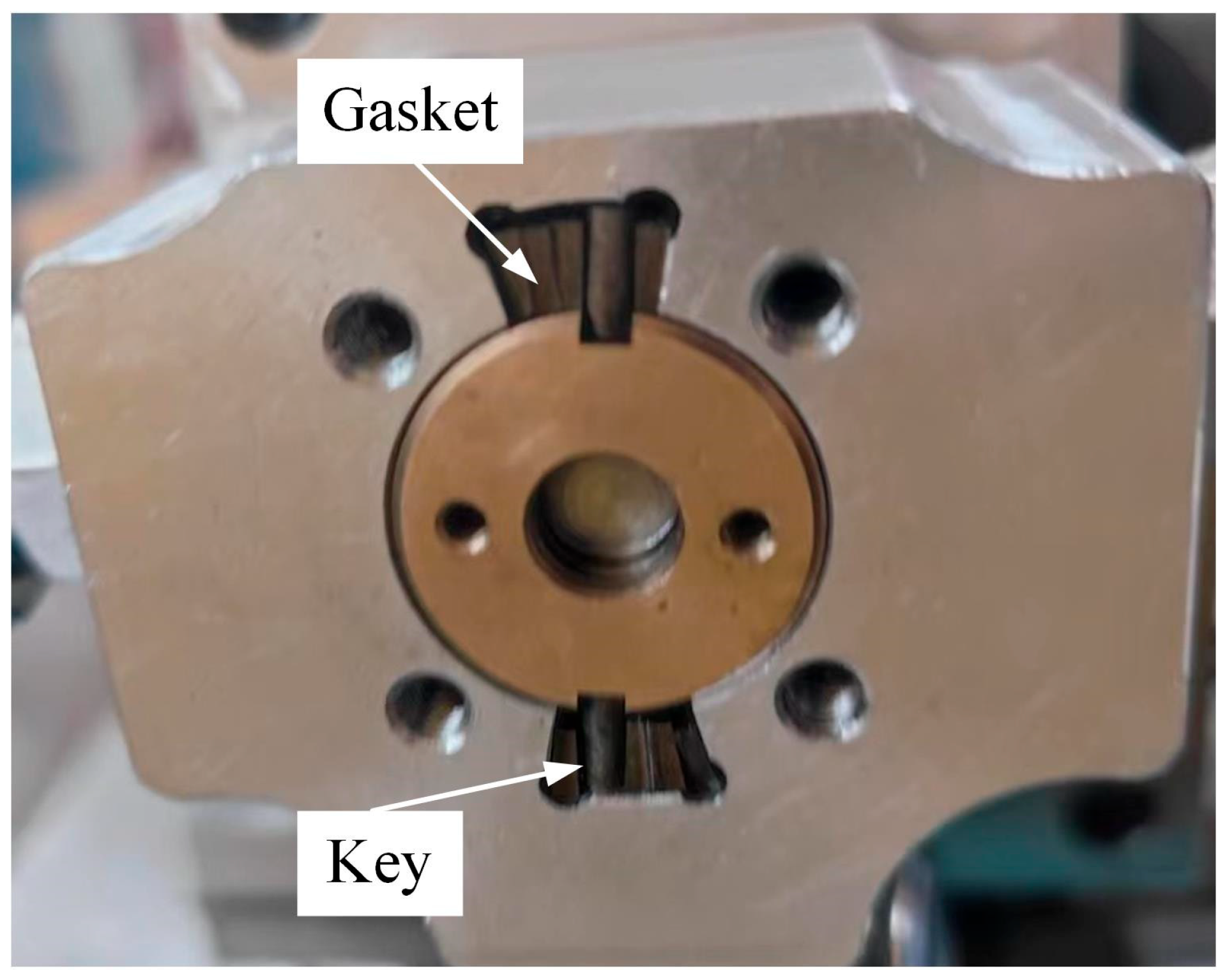
To study the variable displacement characteristics of the pump, we used gaskets and keys to change the cylinder rotation angle for experiments. The cylinder rotation angles were 0°, 6°, 12°, −6°, and −12° through eight gaskets, as shown in Figure 11. The displacement of the pump and the volumetric efficiency and mechanical efficiency of the pump are studied when the cylinder rotation angle is different.
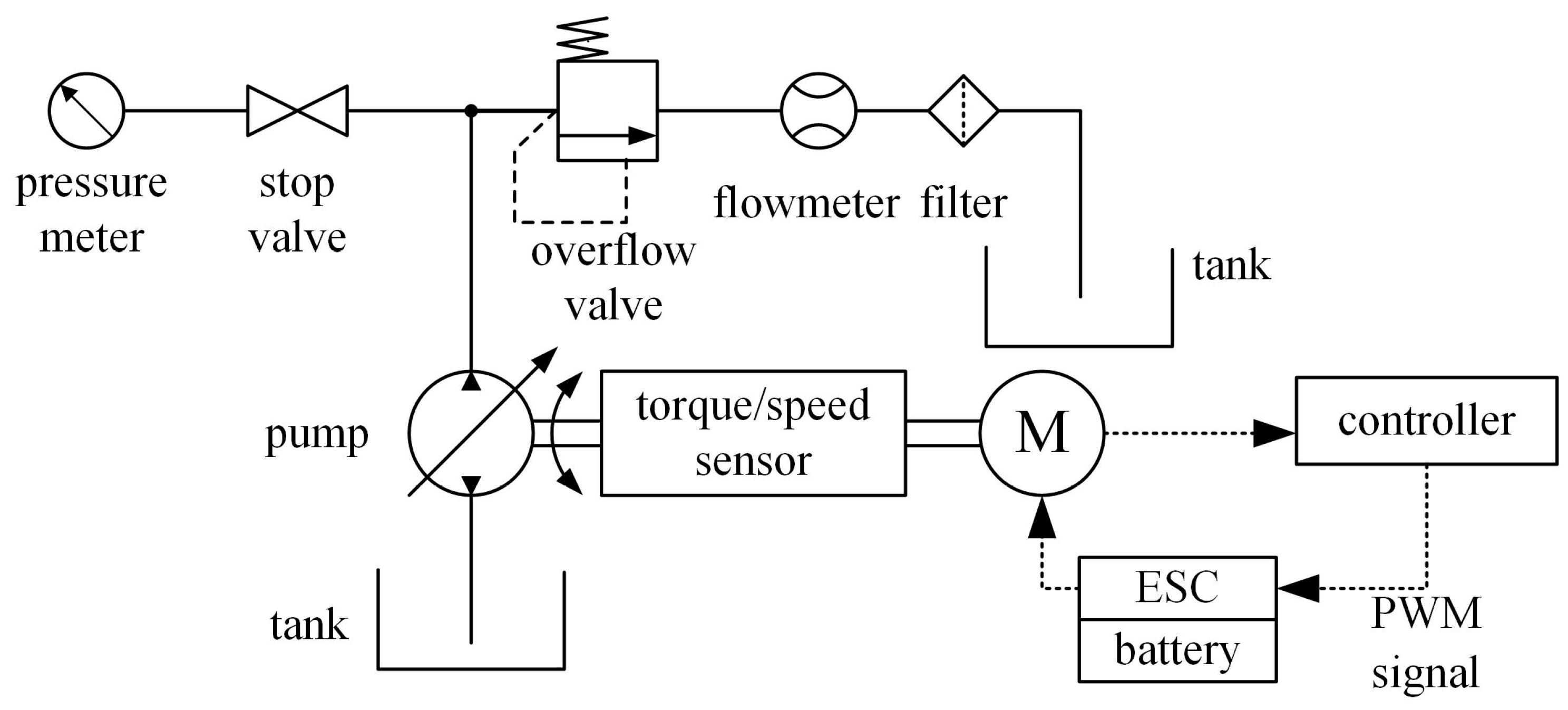
The experimental circuit is shown in Figure 12.
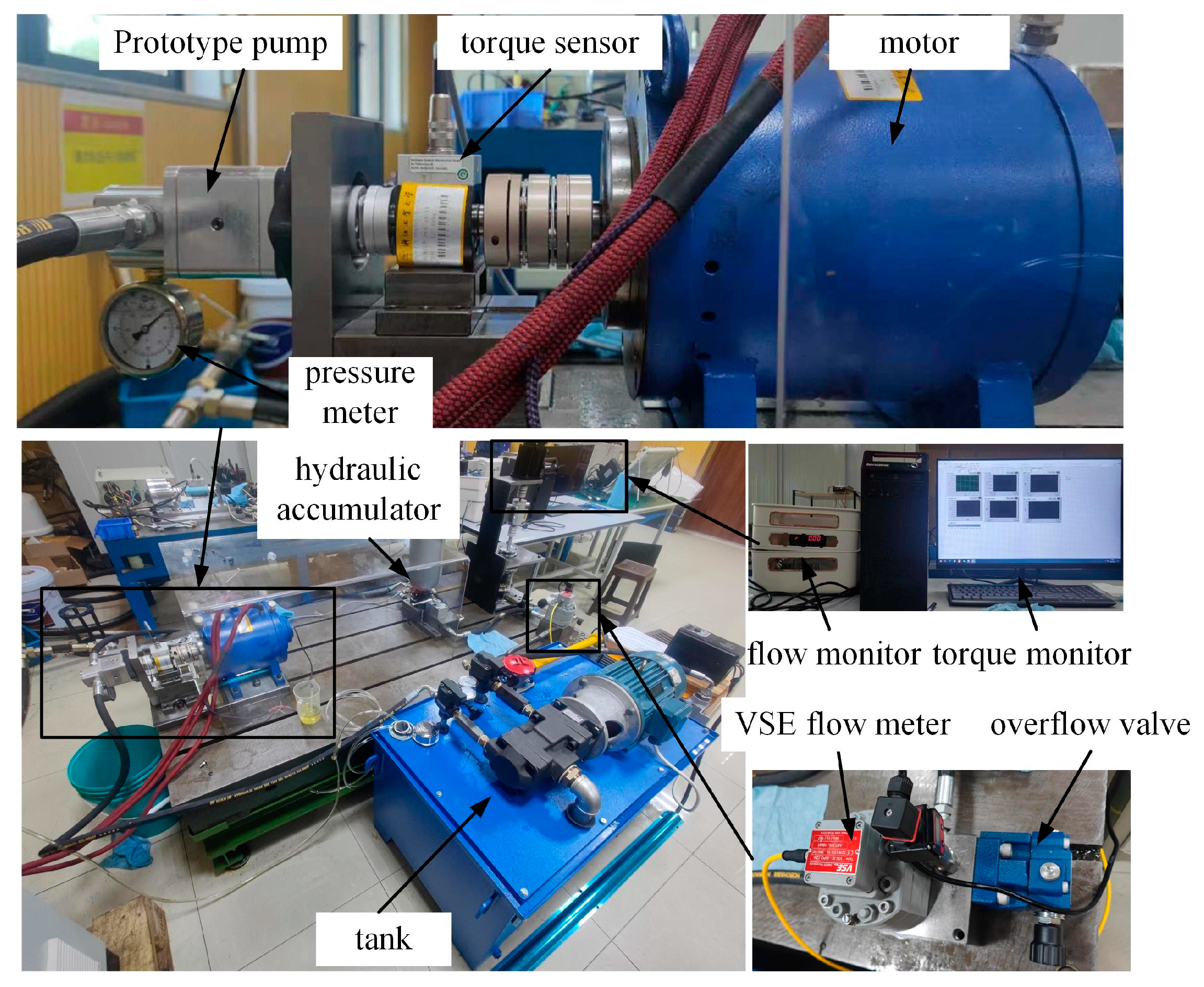
The test bench is shown in Figure 13, which is mainly composed of a speed-regulating motor, a torque/speed sensor, bellows coupling, a prototype pump, an overflow valve, a flow meter, etc. The parameters of the main test instruments can be seen in Table 2.
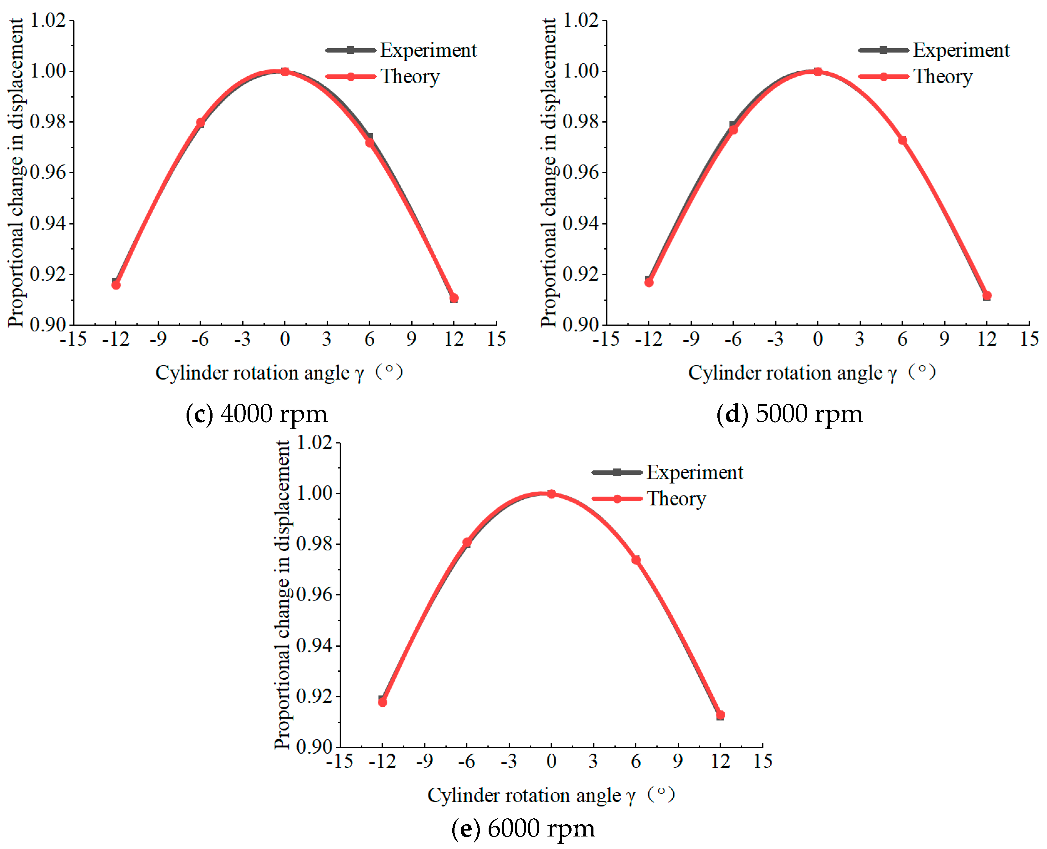
The theoretical displacement of the pump when the cylinder rotation angle is 0, ±6°, and ±12° is 2.2 mL/r, 2.16 mL/r, 2.04 mL/r, and mL/r, respectively. The displacement of the pump under several different cylinder rotation angles was tested when the motor speed was 2000 rpm, 3000 rpm, 4000 rpm, 5000 rpm, and 6000 rpm. We set the variable ratio as the ratio of the actual displacement to the maximum displacement at a certain speed. Figure 14 shows the variable ratios of different cylinder rotation angles at different speeds. It can be seen from the figure that the pump’s working speed has no effect on the variable displacement characteristics, and the actual displacement change is close to the theoretical value, thus verifying the correctness of the theoretical model.
By measuring the output flow of the pump and the output torque of the motor under different cylinder rotation angles and other parameters, the volumetric efficiency and mechanical efficiency of the pump under different cylinder rotation angles can be calculated, as shown in Figure 15.
It can be seen from the figure that when the load pressure is constant, the higher the motor speed is, the higher the volume efficiency of the variable pump is and the lower the mechanical efficiency is. As the cylinder rotation angle increases, the volumetric efficiency and mechanical efficiency of the pump have different degrees of decline. When the cylinder rotation angle is 12°, the pump output flow is reduced by approximately 9%, the volumetric efficiency is reduced by approximately 2%, and the mechanical efficiency is reduced by approximately 5%. The efficiency decreases less when the cylinder rotation angle is negative. The low mechanical efficiency of the prototype is mainly caused by the low machining accuracy.

6. Conclusions

(1)
For the 2D pump with the piston groove distribution structure, the displacement of the pump can be changed by rotating the cylinder block, and bidirectional variables can be realized. When the 2D pump cylinder rotation angle increases from 0° to 45°, the theoretical displacement decreases from 2.2 mL/r to 0, the cylinder rotation angle continues to increase, the pump is reversed until the cylinder rotation angle is 90°, and the displacement reaches the maximum.
(2)
According to the simulation analysis, when the cylinder rotation angle is negative, that is, when the rotation direction of the cylinder is the same as that of the pump, the flow backflow can be reduced, and the pressure pulsation can also be reduced when the flow distribution window switches. If the cylinder rotation angle is positive, increasing the cylinder rotation angle will increase the flow backflow and pressure pulsation.
(3)
When the pump displacement is reduced by changing the cylinder rotation angle, the volumetric efficiency and mechanical efficiency will decrease. Experiments show that when the cylinder rotation angle increases to 12°, the volumetric efficiency is reduced by approximately 2% and the mechanical efficiency is reduced by approximately 5%. It can be seen that the cylinder rotation angle also has an upper limit, and studying the appropriate rotation angle range is also a future research direction.
(4)
A cylinder rotation control mechanism is added to the 2D pump, which can only change the displacement by adjusting the motor speed so a variable displacement mode is added to the 2D pump and a bivariable 2D pump that can adapt to more working conditions is obtained. When the 2D pump works with small displacement, the motor speed need not be reduced too much to avoid the adverse effects of low-speed operation of the motor.
(5)
The experiment is completed by adding gaskets to change the cylinder rotation angle, and the load experimental results of the variable displacement characteristics of the bivariable 2D pump are obtained. Compared with the simulation analysis results, the experimental data are essentially consistent with the simulation, and the relationship curve between the cylinder rotation angle and the pump displacement is verified.

Author Contributions

Conceptualization, J.R.; data curation, Z.Y.; software, Z.Y.; supervision, J.R.; visualization, X.J.; writing—original draft, T.X. and X.J.; writing—review and editing, T.X. and X.J. All authors have read and agreed to the published version of the manuscript.

Funding

This research was funded by the National Natural Science Foundation of China (No. 51775500) and the National Key Research and Development Program of China (No. 2019YFB2005204).

Data Availability Statement

The original contributions presented in the study are included in the article, further inquiries can be directed to the corresponding author.

Conflicts of Interest

The authors declare that there are no conflicts of interest.

Nomenclature

p1Instantaneous pressure of the left Chamber, MPa
βeBulk modulus of the oil
qFlow in or out of the left lumen, m3/s
qcLeakage flow, m3/s
VInstantaneous volume of the left lumen, m3
nRotation speed, r/min
DOuter diameter of piston, m
dInner diameter of piston, m
γCylinder rotation Angle (clockwise rotation is positive direction), °
VminVolume of the cavity at the left limit position of the piston, m3
BTotal width of the constant length slot, B = 2b2b1b4, m
b1Axial length of drain window, m
b2Length flow distribution slot
b3Minimum axial seal length between left and right cavities of piston, m
b4Axial length of oil absorption window, m
CdFlow coefficient
AFlow area of the distribution window, m2
pinSuction port pressure, MPa
poutOil drain pressure, MPa
ρOil density, kg/m3
l0Maximum seal length of left piston rod, m
sPiston displacement, m
δGap between piston and cylinder block, m
vPiston velocity, m/s
p2Instantaneous pressure of the right Chamber, MPa
a1The length of the cylinder window circumference, m
a2Seal width between piston slots, m
a3Circumferential variable seal width for outlet leakage into low pressure chamber, m
a4Circumferential variable seal width for high pressure cavity leakage to the suction port, m

References

  1. Lou, Q.S.; Zhu, L.S.; Niu, K.; Si, S.C. Research on Control System of Hydraulic Bionic Quadruped Robot. Microcontroll. Embed. Syst. 2015, 15, 37–40. [Google Scholar]
  2. Jiao, Y.S. The development and prospect of hydraulic power system in civil aircrafts. Aeronaut. Sci. Technol. 2019, 30, 1–6. [Google Scholar]
  3. Zhang, S.Z.; Liu, Y.; Li, S.; Zhang, X.F. Single and Double Pump Controlled Distributed Hydraulic System of Excavator Using Active Disturbance Rejection Control. Chin. Hydraul. Pneum. 2023, 47, 42–50. [Google Scholar]
  4. Hong, Y.S.; Doh, Y.H. Analysis on the friction losses of a bent-axis type hydraulic piston pump. KSME Int. J. 2004, 18, 1668–1679. [Google Scholar] [CrossRef]
  5. Li, J.; Fu, Y.L.; Wang, Z.L. Present Development Status and Key Technology Research of Airborne Electro-Hydrostatic Actuation System. Aeronaut. Manuf. Technol. 2005, 48, 73–77. [Google Scholar]
  6. Qiu, X.S. Research on the Advanced Actuators Technique. Aeronaut. Sci. Technol. 2009, 04, 6–8. [Google Scholar]
  7. Xin, H.T.; Wang, S.P.; Jiao, Z.X. Multidisciplinary Modeling Technology for Virtual Test and Simulation Platform of Electro-hydraulic Actuator. Mach. Tool Hydraul. 2008, 10, 122–126+143. [Google Scholar]
  8. Lv, F.; Xu, B.; Zhang, J.H. Simulative Analysis of Piston Posture and Piston/Cylinder Interface Leakage of EHA Pumps by the Influence of Rotating Speed. J. Mech. Eng. 2018, 54, 123–130. [Google Scholar] [CrossRef]
  9. Yang, H.Y.; Zhang, B.; Xu, B. Development of Axial Piston Pump/motor Technology. J. Mech. Eng. 2008, 44, 1–8. [Google Scholar] [CrossRef]
  10. Ouyang, X.P.; Wang, T.Z.; Fang, X. Research Status of the High Speed Aircraft Piston Pump. Chin. Hydraul. Pneum. 2018, 2, 1–8. [Google Scholar]
  11. Chao, Q.; Zhang, J.; Xu, B.; Huang, H.; Pan, M. A Review of High-Speed Electro-Hydrostatic Actuator Pumps in Aerospace Applications: Challenges and Solutions. J. Mech. Des. 2019, 141, 050801. [Google Scholar] [CrossRef]
  12. Wiegand, C. F-35 Air Vehicle Technology Overview. In Proceedings of the 2018 Aviation Technology, Integration, and Operations Conference, Atlanta, GA, USA, 25–29 June 2018; AIAA AVIATION Forum. American Institute of Aeronautics and Astronautics: Reston, VA, USA, 2018. [Google Scholar]
  13. Robbins, D.; Bobalik, J.; Stena, D.D.; Martin, N.; Plag, K.; Rail, K.; Wall, K. F-35 Subsystems Design, Development and Verification. In Proceedings of the 2018 Aviation Technology, Integration, and Operations Conference, Atlanta, GA, USA, 25–29 June 2018; AIAA AVIATION Forum. American Institute of Aeronautics and Astronautics: Reston, VA, USA, 2018. [Google Scholar]
  14. Eaton Aerospace Group. A Descriptive Summary of Vickers:Inline Pumps and Their Application. Available online: https://www.eaton.com.cn/cn/en-us/products/pumps.html (accessed on 25 June 2016).
  15. Guo, S.R.; Chen, J.H.; Lu, Y.L.; Wang, Y.; Dong, H.K. Hydraulic piston pump in civil aircraft: Current status, future directions and critical technologies. Chin. J. Aeronaut. 2020, 33, 16–30. [Google Scholar] [CrossRef]
  16. Ernst, M.; Ivantysynova, M.; Vacca, A. Shaping the Piston-Cylinder Interfaces of Axial Piston Machines for Running in the High-Pressure Regime with Water as the Hydraulic Fluid. Proc. Inst. Mech. Eng. Part C J. Mech. Eng. Sci. 2022, 236, 095440622110686. [Google Scholar] [CrossRef]
  17. Wang, Y.; Wang, X.Q.; Guo, S.R.; Lu, Y.L.; Liu, S. Fatigue analysis and life prediction method for cylinder block of aviation piston pump. J. Beijing Univ. Aeronaut. Astronaut. 2019, 45, 1314–1321. [Google Scholar]
  18. Chao, Q.; Zhang, J.; Xu, B.; Wang, Q.; Lyu, F.; Li, K. Integrated slipper retainer mechanism to eliminate slipper wear in high-speed axial piston pumps. Front. Mech. Eng. 2022, 17, 1. [Google Scholar] [CrossRef]
  19. Ouyang, X.P. Modern Hydraulics for Aircrafts; Zhejiang University Press: Hangzhou, China, 2016. [Google Scholar]
  20. Zhang, Z.Y.; Zhang, C.C.; Lu, C.; Ruan, J. Design of 2D Hydraulic Plunger Pump. Chin. Hydraul. Pneum. 2017, 107–111. [Google Scholar]
  21. Ruan, J.; Li, J.Y.; Jin, D.C. Research and feasibility verification of two-dimensional (2D) piston pump. J. Zhejiang Univ. Technol. 2017, 45, 264–269. [Google Scholar]
  22. Wu, H. Two Kinds of Transmission Structure Miniature Water Pump Design and Research. Master’s Thesis, Zhejiang University of Technology, Hangzhou, China, 2022. [Google Scholar]
  23. Huang, Y. Research on the Efficiency Characteristics of High-Speed Two-Dimensional Piston Pumps. Ph.D. Thesis, Zhejiang University of Technology, Hangzhou, China, 2020. [Google Scholar]
  24. Ruan, J.; Jin, D.C.; Shentu, S.N.; Wu, C.S. Research and feasibility verification of two–dimensional (2D) tandem pump. Chin. Hydraul. Pneum. 2017, 11, 1–5. [Google Scholar]
  25. Wang, H.Y.; Ding, C.; Huang, Y.; Li, S.; Ruan, J. Design and research of 2D piston pumps with a stacked cone roller set. Proc. Inst. Mech. Eng. Part C-J. Mech. Eng. Sci. 2022, 236, 5. [Google Scholar] [CrossRef]
  26. Ivantysyn, J.; Ivantysynova, M. Hydrostatic Pumps and Motors: Principles, Design, Performance, Modelling, Analysis, Control and Testing; Tech Books International: New Delhi, India, 2003. [Google Scholar]
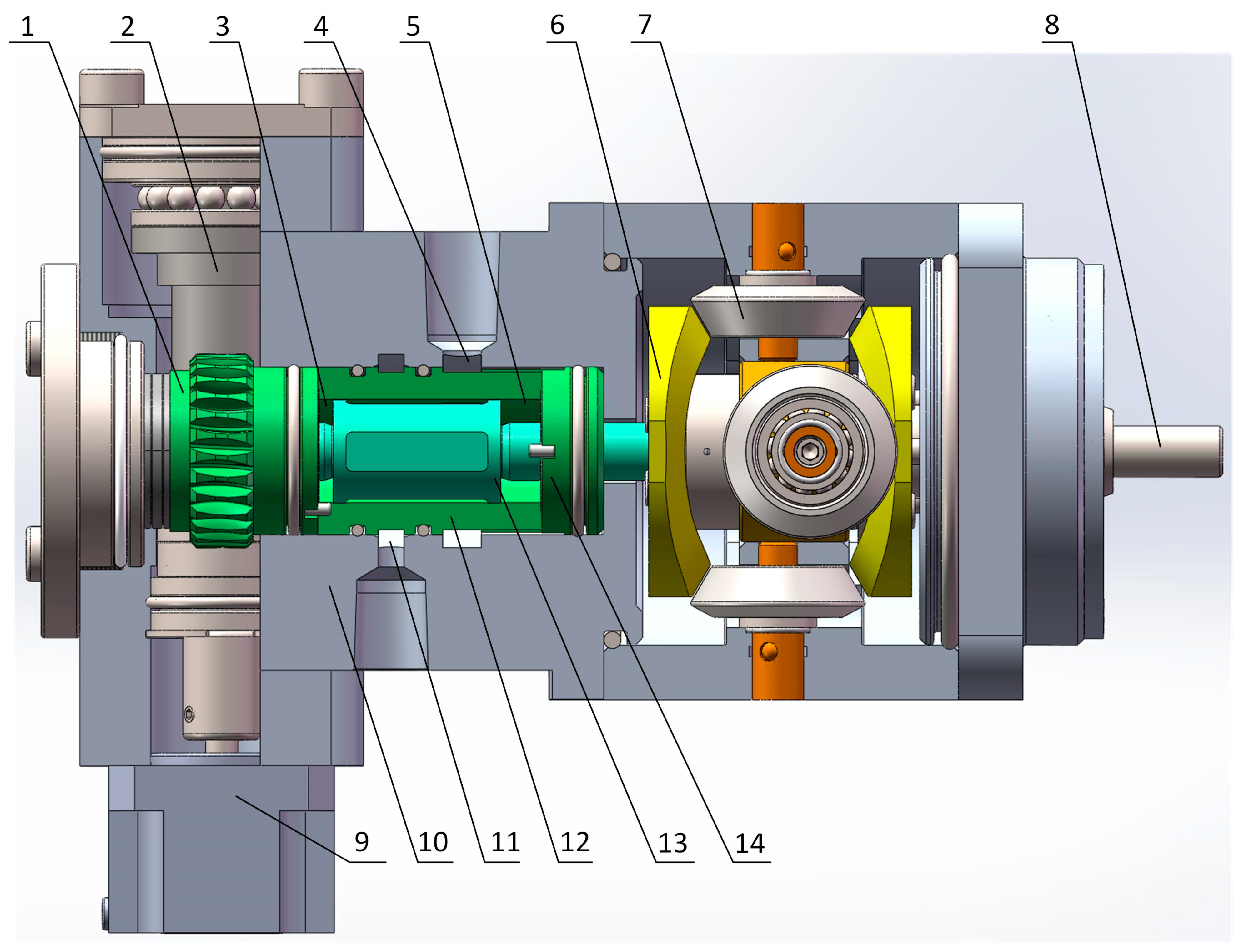
Figure 1. Schematic structural diagram of 2D bivariable pump. 1—Worm gear, 2—Worm, 3—Left chamber, 4—Inlet, 5—Right chamber, 6—Cam guides, 7—Cone roller set, 8—Transmission shaft, 9—Motor, 10—Pump body, 11—Outlet, 12—Cylinder, 13—Piston, 14—Sealing ring.
Energies 17 01725 g001
Figure 2. Working principle diagram of 2D bivariable pump. (a) Distribution section diagram, (b) circumferential expansion diagram, (c) schematic diagram of driving mechanism.
Energies 17 01725 g002
Figure 3. Distribution process of 2D bivariable pump (From (a) to (e) is a complete cycle).
Energies 17 01725 g003
Figure 4. Pump leakage loss diagram (The green part represents the piston).
Energies 17 01725 g004
Figure 5. The flow chart of the simulation program.
Energies 17 01725 g005
Figure 6. Relationship between pump displacement and cylinder rotation angle.
Energies 17 01725 g006
Figure 7. Effect of cylinder rotation angle on piston chamber pressure.
Energies 17 01725 g007
Figure 8. Effect of cylinder rotation angle on leakage in piston chamber.
Energies 17 01725 g008
Figure 9. Effect of cylinder rotation angle on pump outlet flow.
Energies 17 01725 g009
Figure 10. Effect of cylinder rotation angle on volumetric efficiency.
Energies 17 01725 g010
Figure 11. Experimental pump.
Energies 17 01725 g011
Figure 12. Experimental circuit diagram.
Energies 17 01725 g012
Figure 13. Prototype pump test bench.
Energies 17 01725 g013
Figure 14. Variable ratio of the pump at different speeds.
Energies 17 01725 g014aEnergies 17 01725 g014b
Figure 15. Efficiency curve obtained from the experiment. (a) Volumetric efficiency change curves under different cylinder rotation angles. (b) Mechanical efficiency change curves under different cylinder rotation angles. (c) Total efficiency change curve under different cylinder rotation angles.
Energies 17 01725 g015
Table 1. Simulation parameters.
DescriptionValueDescriptionValue
Rotation speed n (rpm)6000Oil dynamic viscosity μ (Pa∙s)0.02
Loading pressure (MPa)27Gap between piston and cylinder block δ (m)5 × 10⁻⁶
Piston stroke h (m)0.004Maximum seal length of left piston rod l o 1 (m)0.01
Bulk modulus of the oil β e (Pa)0.95 × 10⁹Axial length of oil absorption window b 4 (m)0.006
Outer diameter of piston D (m)0.016Axial length of drain window b 1 (m)0.004
Inner diameter of piston d (m)0.009Flow coefficient C d 0.62
Tank pressure (Pa)0Minimum axial seal length between left and right cavities of piston b 3 (m)0.002
Length flow distribution slot b 2 (m)0.022Oil density ρ ( k g / m 3 )833
Minimum volume of piston chamber V m i n ( m 3 )1.35 × 10⁻⁶
Table 2. Parameters of main test instruments.
NameParameter
Kistler 4503B strain type torque/speed sensortorque 0–20 N∙m, precision ± 0.05%
rotational speed 0–18,000 r/min
MIK-P300 pressure sensorpressure 0–10 Mpa, precision ± 0.3%
VSE-58809 flow meterrange 0.05–80 L/min, precision ± 0.3%
Disclaimer/Publisher’s Note: The statements, opinions and data contained in all publications are solely those of the individual author(s) and contributor(s) and not of MDPI and/or the editor(s). MDPI and/or the editor(s) disclaim responsibility for any injury to people or property resulting from any ideas, methods, instructions or products referred to in the content.