
Performance Characterization of Hardware/Software Communication Interfaces in End-to-End Power Management Solutions of High-Performance Computing Processors

 , , ,
, , ,  and
and 
Abstract
1. Introduction
Contribution
- We extend the FPGA-based HIL introduced in [5] to analyze the communication backbone between high-level OSPM agents to the LLC’s HW and FW by integrating the Linux SCMI SW stack and by implementing an SCMI mailbox unit (SCMI-MU) compliant with MHU-v1 functionality.
- We characterize the performance of HW/SW low-level PMIs in Arm architectures based on latency metrics. We quantify the duration for dispatching an SCMI message through the Linux OSPM stack, resulting in a time of 70.5 µs. Additionally, we measure the processing time of a SCMI response message, yielding an average of 603 µs.
- Using the developed setup, we focus on the entire power management control scheme, assessing how different configurations—namely a periodic and event-driven HLC—introduce latency in the PMI and, consequently, how it affects the end-to-end power management control quality, showing that an acceleration of up to can be achieved in the execution time of a synthetic workload. Ultimately, through the development of an optimized version of the LLC’s control FW, we demonstrate that the latency introduced by the PMI can be reduced from around 1.3 ms to 114 µs, thereby reducing the energy consumption and application execution time of approximately 3%.
2. Background and Related Works
2.1. Overview and Terminology
2.2. HLC Components
2.2.1. HW Layer
2.2.2. PM SW Stack
2.3. LLC Components
2.3.1. HW Layer
2.3.2. PM SW Stack
2.4. HLC-LLC Interface
2.4.1. Industry-Standard FW Layer
2.4.2. OS-Agnostic FW Layer
3. Methodology: HIL Framework on FPGA
 ). ControlPULP is emulated in the Programmable Logic (PL) of the FPGA-SoC, to which we added a SCMI-MU (
 ) to provide the HW transport for SCMI protocol. At the same time, the Linux OS image (
 ) running on the Processing System (PS) has been modified to propagate OSPM requests to the ControlPULP LLC via the SCMI-MU. Additionally, a shared memory interface (
 ) is in place to emulate PM virtual sensors and actuators. Indeed, the simulated plant (
 ) provides a thermal, power, performance, and monitoring framework to simulate the power consumption and temperature of a high-end CPU. The plant simulation is programmed in C and runs on the PS’s Arm A53 cores.
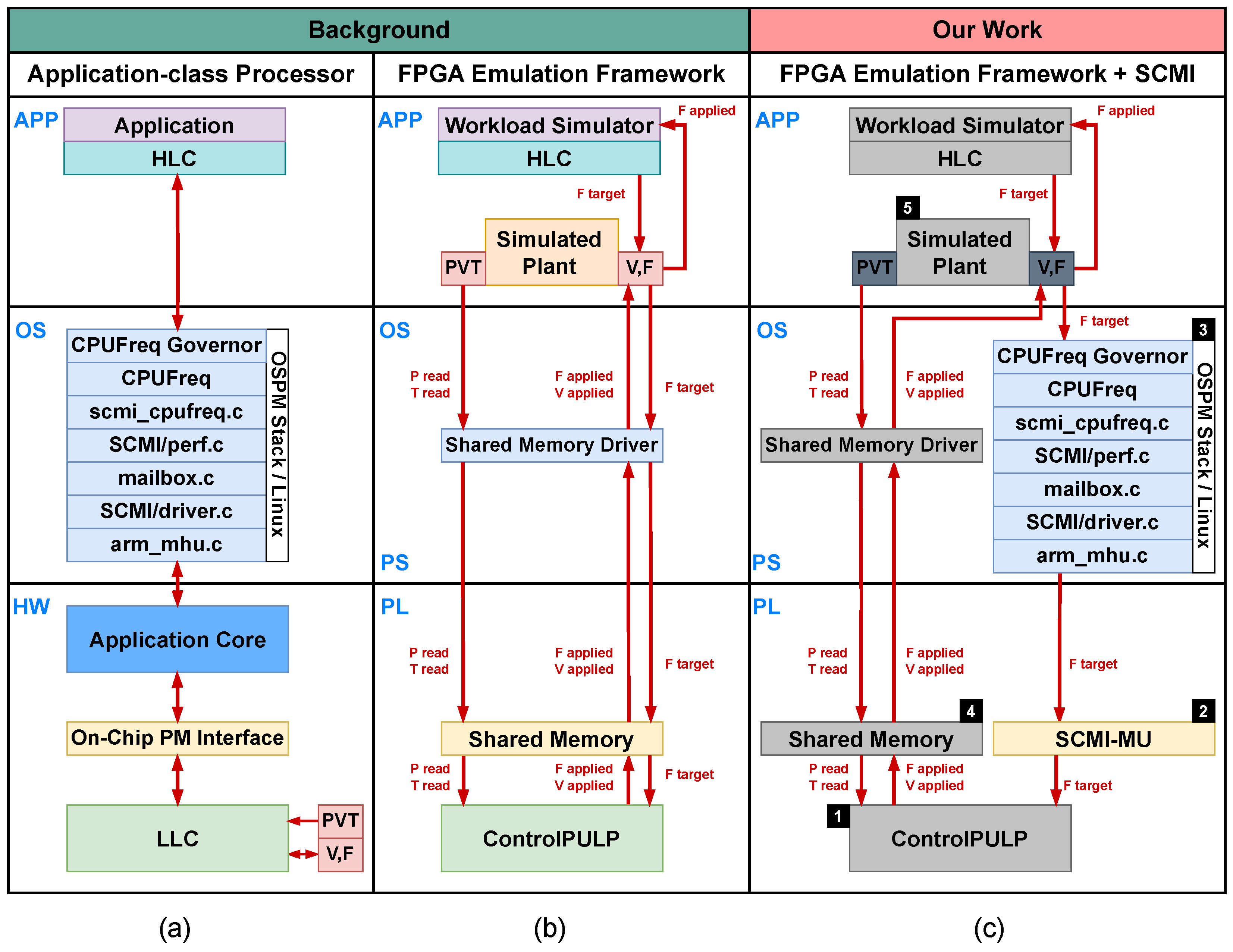
3.1. SCMI-MU Implementation
3.2. Linux SCMI SW Stack
 on the agent side, ranges from store_scaling_setspeed() in cpufreq to message delivery in the shared memory by arm_mhu; the decode window
  on both platform and agent sides ranges from the doorbell-triggered ISR hook in the LLC to the completion-triggered ISR hook in the HLC via arm_mhu; and the reception window
  on the agent side covers function calls until the return of cpufreq.
3.3. LLC SCMI FW Module
3.4. LLC PM Policy Optimized for Latency
3.5. HLC Policy
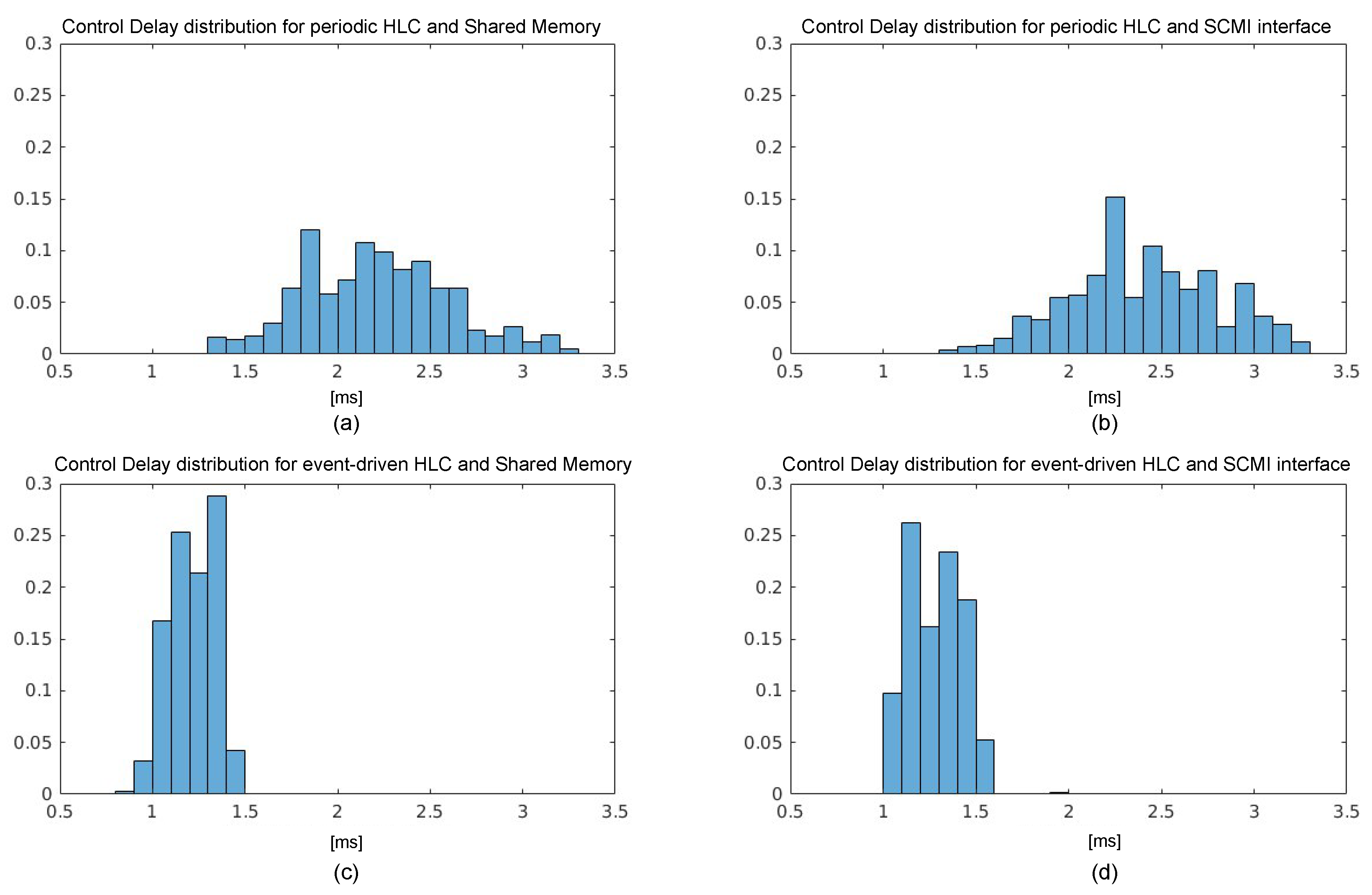
4. Evaluation
4.1. SCMI Latency Characterization
4.1.1. HLC End-to-End Latency Analysis
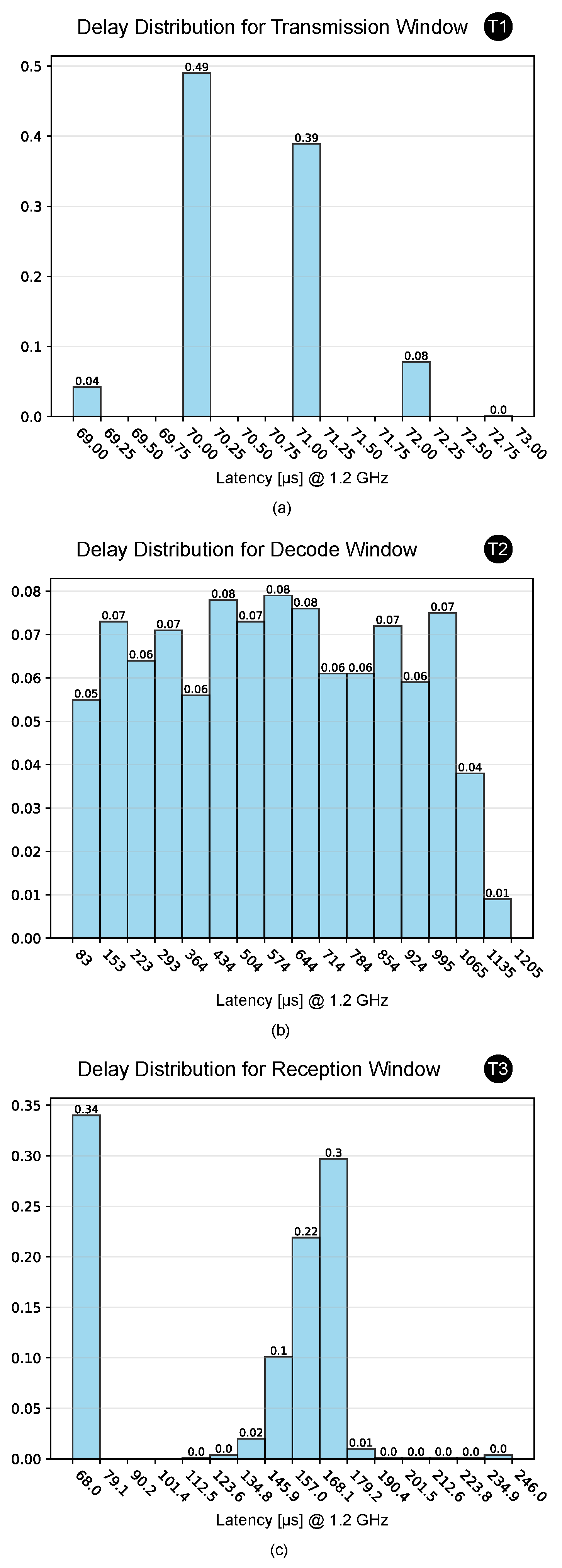
to account for about 8.7%, 74.7%, and 16.5% of the total average time, respectively. Their distribution over 1000 samples is shown in Figure 3. We observe that exhibits a probability distribution falling within a narrow range of only 3 µs, so we consider its mean value of 70.5 µs as relevant. shows an almost uniform distribution in the range between 83 µs and 1205 µs, while for , we can notice a bimodal distribution with two peaks centred around the 75 µs and 164 µs. to the time needed for the OS to detect the interrupt request caused by the doorbell signal, while the variance of is ascribed to the execution of the complete() function, which is responsible for managing the coordination of threads waiting for an SCMI transaction to end.4.1.2. LLC End-to-End Latency Analysis
, which determines the speed at which the messages in the mailbox can be processed by the decoding firmware, and (ii) the size of the SW buffer in the SCMI drivers, which collects pending requests and rejects them when full.4.2. Characterization of End-to-End PM Policy
5. Discussion
6. Conclusions
Author Contributions
Funding
Data Availability Statement
Conflicts of Interest
Abbreviations
| ACPI | Advanced Configuration and Power Interface |
| AP | application-class processors |
| AVSBUS | Adaptive Voltage Scaling Bus |
| BMC | Baseboard Management Controller |
| CD | control delay |
| CLIC | Core-Local Interrupt Controller |
| CPPC | collaborative processor performance control |
| CPU | central processing unit |
| DSA | domain-specific accelerator |
| DVFS | dynamic voltage and frequency scaling |
| FFH | fixed functional hardware |
| FPGA | field programmable gate array |
| FW | firmware |
| GPU | graphic processing unit |
| HBM | high-bandwidth memory |
| HIL | hardware in the loop |
| HLC | high-level controller |
| HPC | high-performance computing |
| HW | hardware |
| ISR | interrupt service routine |
| LLC | low-level controller |
| LPI | low-power idle |
| MSR | model-specific register |
| OCC | On-Chip Controller |
| OPAL | OpenPower abstraction layer |
| OS | Operating System |
| OSPM | operating system-directed configuration and power management |
| PCC | platform communication channel |
| PCF | power control firmware |
| PCU | power control unit |
| PE | processing element |
| PL | Programmable Logic |
| PLL | phase-locked loop |
| PM | power management |
| PMBUS | Power Management Bus |
| PMCA | programmable many-core accelerator |
| PMI | power management interface |
| PS | processing system |
| PVT | Process, Voltage, Temperature |
| RAPL | Running Average Power Limit |
| RTL | Register Transfer Level |
| RTOS | real-time OS |
| SCMI | System Control and Management Interface |
| SCMI-MU | SCMI mailbox unit |
| SoC | system on chip |
| SPR | special purpose register |
| SW | software |
References
- Avgerinou, M.; Bertoldi, P.; Castellazzi, L. Trends in data Centre energy consumption under the European code of conduct for data Centre energy efficiency. Energies 2017, 10, 1470. [Google Scholar] [CrossRef]
- Intel. Power Management in Intel® Architecture Servers. 2009. Available online: https://www.intel.com/content/dam/support/us/en/documents/motherboards/server/sb/power_management_of_intel_architecture_servers.pdf (accessed on 20 September 2024).
- Grover, A. Modern System Power Management: Increasing Demands for More Power and Increased Efficiency Are Pressuring Software and Hardware Developers to Ask Questions and Look for Answers. Queue 2003, 1, 66–72. [Google Scholar] [CrossRef]
- Arm. Power and Performance Management Using Arm SCMI Specification. 2019. Available online: https://developer.arm.com/documentation/102886/001?lang=en (accessed on 20 September 2024).
- Ottaviano, A.; Balas, R.; Bambini, G.; Del Vecchio, A.; Ciani, M.; Rossi, D.; Benini, L.; Bartolini, A. ControlPULP: A RISC-V On-Chip Parallel Power Controller for Many-Core HPC Processors with FPGA-Based Hardware-In-The-Loop Power and Thermal Emulation. Int. J. Parallel Program. 2024, 52, 93–123. [Google Scholar] [CrossRef]
- Silva, V.R.G.d.; Valderrama, C.; Manneback, P.; Xavier-de Souza, S. Analytical Energy Model Parametrized by Workload, Clock Frequency and Number of Active Cores for Share-Memory High-Performance Computing Applications. Energies 2022, 15, 1213. [Google Scholar] [CrossRef]
- Coutinho Demetrios, A.; De Sensi, D.; Lorenzon, A.F.; Georgiou, K.; Nunez-Yanez, J.; Eder, K.; Xavier-de Souza, S. Performance and energy trade-offs for parallel applications on heterogeneous multi-processing systems. Energies 2020, 13, 2409. [Google Scholar] [CrossRef]
- Kocot, B.; Czarnul, P.; Proficz, J. Energy-aware scheduling for high-performance computing systems: A survey. Energies 2023, 16, 890. [Google Scholar] [CrossRef]
- UEFI. ACPI Specification 6.5. 2023. Available online: https://uefi.org/specs/ACPI/6.5/ (accessed on 20 September 2024).
- Arm. Power Control System Architecture. 2023. Available online: https://developer.arm.com/documentation/den0050/d/?lang=en (accessed on 20 September 2024).
- Bartolini, A.; Rossi, D.; Mastrandrea, A.; Conficoni, C.; Benatti, S.; Tilli, A.; Benini, L. A PULP-based Parallel Power Controller for Future Exascale Systems. In Proceedings of the 2019 26th IEEE International Conference on Electronics, Circuits and Systems (ICECS), Genoa, Italy, 27–29 November 2019; pp. 771–774. [Google Scholar] [CrossRef]
- Balas, R.; Ottaviano, A.; Benini, L. CV32RT: Enabling Fast Interrupt and Context Switching for RISC-V Microcontrollers. arXiv 2023, arXiv:2311.08320. [Google Scholar] [CrossRef]
- Rosedahl, T.; Broyles, M.; Lefurgy, C.; Christensen, B.; Feng, W. Power/Performance Controlling Techniques in OpenPOWER. In High Performance Computing, Proceedings of the ISC High Performance 2017, Frankfurt, Germany, 18–22 June 2017; Kunkel, J.M., Yokota, R., Taufer, M., Shalf, J., Eds.; Springer: Cham, Switzerland, 2017; pp. 275–289. [Google Scholar]
- Arm. SCP-Firmware—Version 2.13. 2023. Available online: https://github.com/Arm-software/SCP-firmware (accessed on 20 September 2024).
- Arm. Arm Cortex-A75 Technical Reference Manual. 2024. Available online: https://developer.arm.com/documentation/ka005129/latest/ (accessed on 20 September 2024).
- Patterson, D.A.; Hennessy, J.L. Computer Organization and Design, 2nd ed.; Morgan Kaufmann Publishers: Burlington, MA, USA, 1998; p. 715. [Google Scholar]
- Bartolini, A.; Cacciari, M.; Tilli, A.; Benini, L. Thermal and Energy Management of High-Performance Multicores: Distributed and Self-Calibrating Model-Predictive Controller. IEEE Trans. Parallel Distrib. Syst. 2013, 24, 170–183. [Google Scholar] [CrossRef]
- OpenHW Group. CV32E40P: In-Order 4-Stage RISC-V CPU Based on RI5CY from PULP-Platform. 2024. Available online: https://github.com/openhwgroup/cv32e40p (accessed on 20 September 2024).
- Cesarini, D.; Bartolini, A.; Borghesi, A.; Cavazzoni, C.; Luisier, M.; Benini, L. Countdown slack: A run-time library to reduce energy footprint in large-scale MPI applications. IEEE Trans. Parallel Distrib. Syst. 2020, 31, 2696–2709. [Google Scholar] [CrossRef]


| (a) | (b) | ||||||||||
|---|---|---|---|---|---|---|---|---|---|---|---|
| Minimum | Average | Maximum | Increment | Sum | |||||||
| [µs] | [Cycles] | [µs] | [Cycles] | [µs] | [Cycles] | [µs] | [Cycles] | [µs] | [Cycles] | ||
| 69 | 82.60 k | 70.50 | 84.60 k | 73 | 87.60 k | CLIC to ISR | 2.30 | 46 | 2.30 | 46 |
| 83 | 99.60 k | 603.50 | 724.20 k | 1205 | 1446 k | ISR exec. | 5.20 | 104 | 7.50 | 150 |
| 68 | 81.60 k | 133.80 | 160.56 k | 246 | 295.20 k | ISR to dec. task | 0.65 | 13 | 8.15 | 163 |
| Total | 220 | 264 k | 807.80 | 969.36 k | 1449 | 1828 k | Dec task exec. | 5.00 | 100 | 13.15 | 263 |
| Execution Time Speedup [%] | ||
|---|---|---|
| Configuration | Shared Memory | SCMI |
| (i) HLC periodic | 0.00 | |
| (ii) HLC event-driven | 2.75 | 2.71 |
| (iii) HLC event-driven, Opt. Control | 3.18 | 2.89 |
Disclaimer/Publisher’s Note: The statements, opinions and data contained in all publications are solely those of the individual author(s) and contributor(s) and not of MDPI and/or the editor(s). MDPI and/or the editor(s) disclaim responsibility for any injury to people or property resulting from any ideas, methods, instructions or products referred to in the content. |
© 2024 by the authors. Licensee MDPI, Basel, Switzerland. This article is an open access article distributed under the terms and conditions of the Creative Commons Attribution (CC BY) license (https://creativecommons.org/licenses/by/4.0/).
Share and Cite
del Vecchio, A.; Ottaviano, A.; Bambini, G.; Acquaviva, A.; Bartolini, A. Performance Characterization of Hardware/Software Communication Interfaces in End-to-End Power Management Solutions of High-Performance Computing Processors. Energies 2024, 17, 5778. https://doi.org/10.3390/en17225778
del Vecchio A, Ottaviano A, Bambini G, Acquaviva A, Bartolini A. Performance Characterization of Hardware/Software Communication Interfaces in End-to-End Power Management Solutions of High-Performance Computing Processors. Energies. 2024; 17(22):5778. https://doi.org/10.3390/en17225778
Chicago/Turabian Styledel Vecchio, Antonio, Alessandro Ottaviano, Giovanni Bambini, Andrea Acquaviva, and Andrea Bartolini. 2024. "Performance Characterization of Hardware/Software Communication Interfaces in End-to-End Power Management Solutions of High-Performance Computing Processors" Energies 17, no. 22: 5778. https://doi.org/10.3390/en17225778
APA Styledel Vecchio, A., Ottaviano, A., Bambini, G., Acquaviva, A., & Bartolini, A. (2024). Performance Characterization of Hardware/Software Communication Interfaces in End-to-End Power Management Solutions of High-Performance Computing Processors. Energies, 17(22), 5778. https://doi.org/10.3390/en17225778