Abstract
This paper presents a solution to reduce source current ripple in the electrical power supplying a switched reluctance motor (SRM) drive. Source current ripple negatively affects the power source by introducing a variable frequency component and increasing losses in the power source. Reducing the source current ripple is important, especially in battery electric vehicles (BEVs). The solution proposed in this paper for reducing source current ripple is to use a classic DC/DC boost converter connected in series with the SRM power supply system. The key to reducing source current ripple is the DC/DC converter control method proposed and described in this article. This method involves controlling the DC/DC converter synchronized with the speed of the SRM motor DC/DC. To verify the correct operation of the proposed solution, simulation and laboratory tests of an SRM drive were performed, the results of which are shown in this paper.
1. Introduction
Switched reluctance motors (SRMs) are electronically commutated machines characterised by the absence of permanent magnets and windings on the rotor. Thanks to this design, they are highly resistant to damage and can operate in harsh environments [1,2]. In addition, the topology of the power supply system allows an SRM to operate under the condition of partial fault [3]. In practise, SRMs find drive applications that include high-end kitchen robots, concrete drills, aircraft pump drives and more. Unfortunately, SRMs also have disadvantages that limit their wider use. Disadvantages include noisy operation, high torque ripple, and source current ripple [1,2,3,4]. Various design solutions [5] or control algorithms are used to reduce the level of noise generated [6]. Torque ripple is mitigated through appropriate design or, more commonly, through the use of control algorithms [7,8,9,10]. The last disadvantage is the high-ripple source current, which is caused by the demagnetisation process of the windings when the power supply is switched off. The high rms source current values resulting from the source current ripple adversely affect the power source, resulting in higher losses in the source and generating noise [10,11,12,13,14,15,16].
A high level of current ripple negatively affects battery lifespan, as peak current is significantly higher than the average current. This causes an increase in the RMS current. An increase in the battery’s RMS current causes a rise in its temperature. Unfortunately, an excessive increase in current significantly affects battery lifespan [12,13]. According to the study on Li-ion batteries [12], excessive current causes a rapid process of lithium-ion intercalation and deintercalation on the particle surface, which can lead to fatigue and damage to the active material structure. Excessive current can also result in poor uniformity of current distribution within the battery, causing localised lithium plating or inconsistent structural deformation.
To supply electric vehicle drives, DC/DC converters of various configurations are often used [17,18,19]. In work [17], a topology of selected boost converters (isolated and non-isolated) is presented, which may find applications in electric cars. A solution for a multilevel converter is introduced in work [18], where this type of solution is used to power a DC commutator machine. In many cases, this aims to increase the operating voltage of drive motors, thereby improving drive efficiency. For the reduction in current ripple in SRM machines, the level of UDC voltage variation is relatively small.
Various ways of reducing the source current ripple in the SRM drive current input while reducing the filtering capacitance can be found in the literature [14,15,16,20,21].
A method of reducing the filtering capacitance is presented in [22], which involves separating the supply circuit from the filter circuit, so that the voltage on the filter capacitor is higher than the supply voltage. This reduces the capacitance of the filter capacitor, yet increases its operating voltage. Although this method reduces the capacitance of the filter capacitor, it requires converter circuit components with a higher-rated operating voltage, including the capacitor. A four-phase SRM split-voltage midpoint converter power system was used in [23]. In series with the system, a low-cost active filter was applied that improved the power factor (power factor correction—PFC) and reduced the level of the AC mains’ harmonics.
This system is only suitable for SRM drives with an even number of phases and supplies from AC mains. BEVs and hybrid vehicles use electrochemical batteries to power the traction drive units, which are DC-powered via converters. Reducing the source current ripple from the battery reduces battery losses, limits battery heating and thus contributes to extended battery life. Bidirectional converters were applied in [21] to power a synchronous reluctance motor drive (SyncRM) using a battery and supercapacitor. The purpose of the solution included: stabilising the DC-bus voltage; ensuring the proper use of the power flows between the battery and SC while respecting the SOC (state of charge) limits; preventing the SynRM motor from the harmonics that impact the energy storage systems’ lifetimes; reducing the battery current harmonics induced by the electric drive; and minimising the battery current ripples generated by both the SynRM and PWM inverter.
The objective of this paper is to present a method developed by the authors to minimise source current ripple. The suitability of this solution was assessed by performing simulations and laboratory tests. The method developed for the solution is applicable to a wide range of SRM drive operations.
2. Problem of Source Current Ripple
The classic power supply system for SRMs is a half-bridge system, the diagram for a 4-phase SRM is shown in Figure 1.
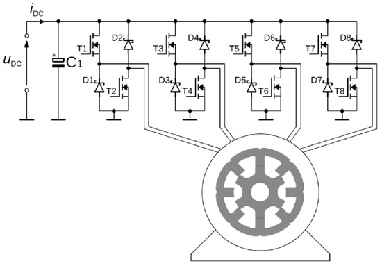
Figure 1.
Schematic of a classic SRM power supply system.
The waveforms of the phase currents (iph1, …, iph4) and the source input current (iDC) with the current control for an SRM supplied with the circuit in Figure 1, are shown in Figure 2.
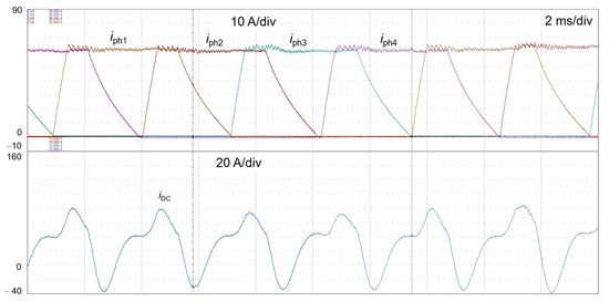
Figure 2.
Waveforms of phase currents and power source current with current control and a speed of 800 rpm.
The pulsed power supply method for the SRM results in large source current ripples and, thus, ripples in the supply voltage. Large source current ripples increase the ratio of the rms current value to the average current value (IDCrms/IDCav). The high IDCrms value causes increased losses in the power source and supply cables, which, in the case of high-powered SRMs, contributes to increased drive operating costs and, in SRMs applied in BEVs, a reduction in the actual driving range. The electrochemical batteries from which BEVs are powered still have the property that their internal resistance varies with temperature, the battery state of charge (SOC), and the battery state of health (SOH). A high source current ripple and, thus, high peak current values also adversely affect the battery life in BEVs. Calculating the average and rms values of the source current shown in the oscillogram (Figure 2) yielded 29 A and 42 A, respectively. The IDCrms/IDCav ratio is 1.45 in this case, meaning there is more than twice the level of loss in the supply circuit with a rippling current than with a constant current supply without ripples.
3. Reduction in Source Current Ripple by the Proposed Method
3.1. Schematic of an SRM Drive with a DC/DC Converter
Figure 3 shows a power supply schematic for an SRM, which uses an additional DC/DC converter to reduce the source current ripple. This is a classic boost converter system. An advantage of this type of converter is the small number of components. Additionally, this converter can conduct high currents, which is important for the tested drive, as the peak phase currents can reach up to 110 A. The converter converts the voltage on the SRM’s DC-link power supply (uDC) in such a way that the source current has the lowest possible ripple. The solution reduces the source current ripple while reducing the filtering capacitance in the DC-link. This paper presents the results of the simulation and the laboratory tests of the properties of an SRM drive powered by a system with and without a DC/DC converter, while discussing the DC/DC converter control method as an original solution developed by the authors. A DC/DC converter open/close switch (SDC/DC_on/off) was used to switch the operating mode of the SRM drive power system. Diode D10 provided protection for the unidirectional power supply against the energy backfeed from the SRM system.
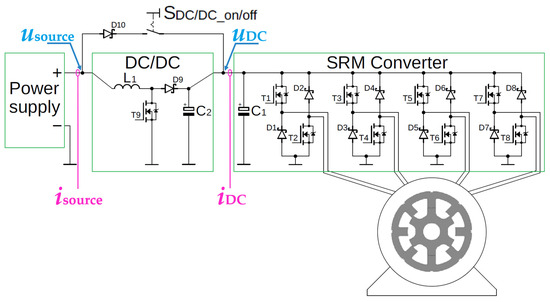
Figure 3.
Schematic of the SRM drive with the DC/DC converter.
The test object was a drive with a four-phase SRM, the basic data of which is specified in Table 1.

Table 1.
Basic data of the SRM studied.
The power supply system shown in Figure 3 was used for simulation and laboratory tests. When the SDC/DC_on/off switch is closed, the SRM is powered by the classic H-type half-bridge system (Figure 1). When the SDC/DC_on/off switch is open, the DC/DC boost converter is switched on in series in the supply path.
3.2. Description of the Proposed Control Method
Example waveforms of the band currents and synchronising pulses for two SRM power supply intervals (θdwell = 19° and θdwell = 15°) are shown in Figure 4. It can be seen from this figure that the minimum uDC level in the DC-link is present when the power supply to the windings of the individual bands is de-energised, regardless of the power supply interval. The waveforms in Figure 4 show that when the power supply to the band winding is de-energised (θoff), the uDC voltage is approximately equal to the usource. Taking advantage of this property, a new control method for the DC/DC converter was proposed to minimise the source current ripple, regardless of the operating point of the SRM drive. A schematic of the proposed control structure for the SRM drive with the DC/DC converter is shown in Figure 5.
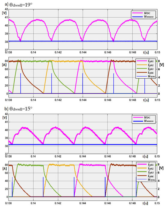
Figure 4.
Waveforms of the band currents iph1 … i ph4, the synchronising pulses usync, and the voltages uDC and usource for the two cases of conduction interval: θdwell = 19° (a) and θdwell = 15° (b).

Figure 5.
Block diagram of the SRM drive reduced of source current ripple.
Two feedback signals are used to achieve the correct operation of the DC/DC inverter. One is the synchronisation signal, or synchronising pulse, (usync) supplied when the power supply to the phase windings is de-energised (θoff). At this time, uDC is present on the SRM controller and latched until the next synchronising pulse is supplied. This uDC sensing procedure protects the system from an uncontrolled increase in the DC voltage. The role of the PI regulator is to stabilise the source voltage at uDC (θoff). The output signal from the PI regulator is the DC/DC converter output current, iDCref, from which the offset ΔiDC is calculated. The offset signal is supplied to a high-speed hysteresis current regulator, which in turn manages the DC/DC converter transistor. Figure 6 shows an example of a closed-loop speed control structure for the SRM drive.
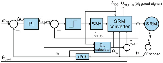
Figure 6.
Block diagram of SRM drive with closed-loop speed control.
Digital differential controllers were used in the phase current feedback loop (iph(1…k)). A PI regulator was used in the SRM speed feedback path. The block “θon calculate” determined the making angle θon. The making angle for a four-phase motor with an 8/6 configuration can be calculated from the signals of drive angular velocity ω, the phase reference current ISRMref and the DC-link voltage uDC using the following relationship:
with: Lu—self-inductance of the motor phase winding in the unaligned position of the rotor; βs and βr—the stator and rotor poles width, respectively. The switch-off angle (θoff) is the sum of the switch-on angle (θon) and the phase winding power supply interval (θdwell):
The phase reference current ISRMref (Figure 6) is determined using a proportional-integral (PI) regulator on the basis of the angular velocity offset (Δω).
Figure 7 shows a schematic of the proposed control algorithm for the DC/DC converter. Upon power-up, the converter current is increased to charge the capacitors in the DC-link circuit so that the voltage UDC equals the source voltage Usource. After starting the SRM, the rotor position angle (θ) is checked, and then, at the moment of the power-off of any phase, the value UDC(θoff) is stored. This value is compared with the voltage Usource, and depending on the sign of the error, the current reference iDCref is either increased or decreased. This function is executed by the PI controller of the DC/DC converter, operating with a sampling time ts = 50 μs. The current iDCref is compared with the source current isource and using an analogue hysteresis current controller (thus very fast), it switches the transistor T9 of the converter on or off. In our solution, the voltage (PI) and current (hysteresis) controllers operate in independent time regimes.
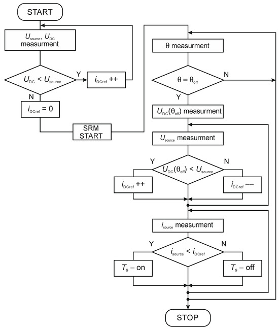
Figure 7.
Proposed of DC/DC converter control algorithm.
4. Study of SRM Drive
4.1. Simulation Results
Simulation tests were carried out in the Matlab/Simulink environment for the SRM, the data for which are shown in Table 1. The tests were carried out for the steady-state drive operation and in dynamic states. Figure 8 shows the waveforms of supply voltages (usource, uDC), phase currents (iph1, …, iph4), synchronising pulses (usync), supply currents (isource, iDC), and SRM electromagnetic torque (Te) for the tested drive. The waveforms were generated for a speed of 1000 rpm, with an average SRM torque of TeAV = 12.8 Nm, resulting in a forced reference current of ISRMref = 80 A. The SRM power supply interval was set to θdwell = 20°. Note that a change in speed causes a change in the frequency of the current and voltage pulse rate of the DC-link, which is not a favourable phenomenon as it generates variable frequency interference. In the case shown in Figure 8, the ripple frequency of the voltage and current in the DC-link (fiDC) is 400 Hz. By observing the source voltage and current waveforms (usource, isource), it is clear that the source current ripple was suppressed.
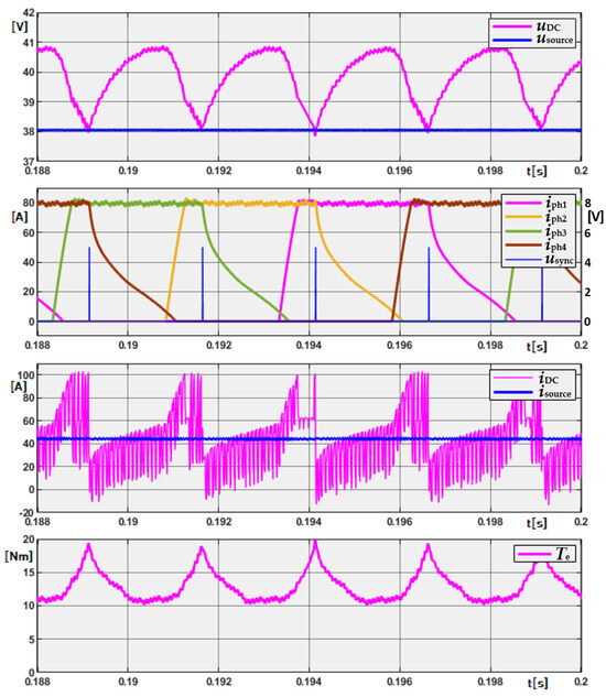
Figure 8.
Waveforms of the band currents iph1 … iph4, iDC and isource, the synchronising pulses usync, the electromagnetic torque Te, and the voltages uDC and usource for the conduction intervals θdwell = 20° and ISRMref = 80 A.
Figure 9 shows the waveforms of supply voltages (usource, uDC), phase currents (iph1, … iph4), supply currents (isource, iDC) and the speed simulation-generated for SRM start-up. The SRM speed varied from 0 to 1000 rpm, with a torque load of 2 Nm. Comparing the usource and uDC waveforms, very good suppression of source voltage ripple is seen. The uDC voltage of the DC-link has a variable frequency, which is a function of the SRM speed. When the SRM reaches a steady state speed, there is a noticeable increase in this voltage, which is associated with a reduction in the SRM current draw. This is certainly a disadvantageous phenomenon and requires additional protections for the SRM system. A comparison between isource and iDC clearly reveals a reduction in the source current ripple. Some current ripple is noticeable at low SRM speeds of up to 200 rpm, and this is related to the long intervals between synchronising pulses.
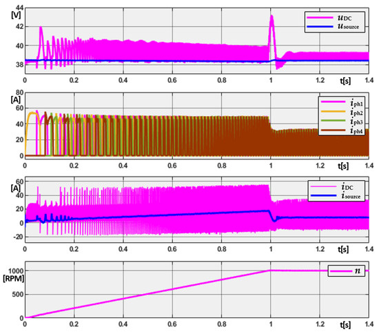
Figure 9.
Waveforms of the band currents iph1 … iph4, iDC and isource, speed n, uDC and usource, with a conduction interval of θdwell = 20° and a load torque of TL = 2 Nm for the SRM drive start-up with the proposed filtering.
4.2. Test Stand
To verify the proposed SRM drive control algorithm, a laboratory test stand was built, an overview of which is shown in Figure 10. The SRM was mechanically coupled to a DC machine that operated as a generator with controllable braking torque. A Yokogawa DL850 oscilloscope recorder (Tokyo, Japan) was used to record the waveforms, and a Yokogawa WT1800 power analyzer was used to measure the SRM drive and DC/DC converter parameters. The SRM converter and DC/DC converter were built as separate power modules. The DC/DC converter, SRM converter, and dynamometer were managed from a PC via a DS1103 interface card. An incremental encoder, also supported by the interface card, was used to sense the rotor position. Using the SRM drive’s simulation tests, the settings of the SRM speed and DC/DC converter voltage controllers were preset. The SRM control structure shown in Figure 6 was entirely implemented using the DS1103 interface card. An SRM drive speed control algorithm was implemented in the interface card, where the phase reference current (ISRMref) was determined via a PI regulator. Similarly, the dSpace card calculated the reference current of the DC/DC converter (iDCref). To determine the offset for the converter reference current iDCref regulator, the DC-link voltage value uDC was latched and snapped when the angle θoff was reached. Due to the high dynamics of the current drawn by the SRM inverter, the dSpace card was not able to maintain a stable source current value. Therefore, a very fast analogue hysteresis current controller for the DC/DC converter was designed and built, to which the iDCref calculated with the dSpace card was sent. This regulator was based on TL072 operational amplifiers, which implement follow-up modulation.
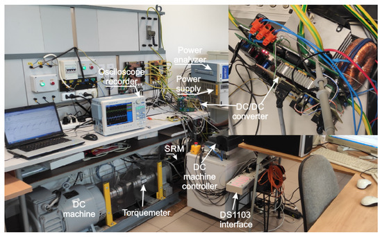
Figure 10.
View of the test stand.
4.3. Laboratory Results
Laboratory tests of the SRM drive were performed on the laboratory test stand shown in Figure 10. The SRM drive was powered by an Agilent 60 V/110 A, stabilised power supply (Santa Clara, CA, USA). To evaluate the effectiveness of the solution proposed in this work, tests were performed without a DC/DC converter (SDC/DC_on/off = on) and with the DC/DC converter (SDC/DC_on/off = off). The tests were performed for the steady-state operation and for the dynamic states of the SRM drive. Figure 11 shows the waveforms of uDC, isource, iDC, current, and iph1 recorded at 1000 rpm, the load torque of 7.5 Nm, and the power supply angle of 20°. With a classic SRM power supply (without the DC/DC converter), a very high source current ripple can be seen. Theoretically, in this case, the waveforms of isource and iDC should be identical, but according to the diagram shown in Figure 3, with the SDC/DC_on/off switch made, the closed iDC includes the current of capacitor C2, hence, the ripple of this current was higher. The large range of isource variations (i.e., between 0 and 90 A) also resulted in source voltage variations (between 35 V and 40 V). The phase current was limited by the controller to 80 A. The Isource_rms value in this case was 50 A and the average Isource_av = 37.2 A.
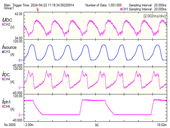
Figure 11.
Waveforms for uDC, isource, iDC, iph1 at n = 1000 rpm, TL = 7.5 Nm, θdwell = 20°, with the SRM powered by the classic controller.
When the SDC/DC_on/off switch was open, the DC/DC converter, controlled according to the algorithm proposed in this paper, was activated. Figure 12 shows the usync rising edge synchronisation signal, and the usource with isource, iDC, and iph1 currents. The waveforms were recorded for the same SRM drive operating point as when the SDC/DC_on/off switch was closed. From the waveforms shown, it is clear that the source current and voltage ripples were virtually eliminated. The power source voltage ripple was also reduced. As a result of the DC/DC converter operation, there was an increase in the average and maximum DC link voltages (UDCav = 40.1 V and UDCmax = 41.6 V) with respect to the SRM drive system operation without the DC/DC converter. Reducing the source current ripple reduced the generation of the variable component of the power source voltage, the frequency of which varies with motor speed. In addition, the reduction in the rms source current value resulted in reduced losses in the power source. This is particularly important when the SRM drive is powered by a battery bank, whose internal resistance varies with SOC and temperature.
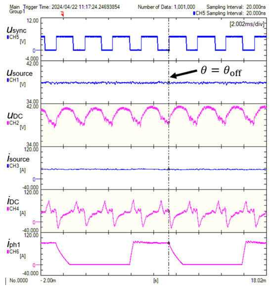
Figure 12.
Waveforms for usync, usource, uDC, isource, iDC, and iph1 of the SRM drive at n = 1000 rpm, TL = 7.5 Nm, θdwell = 20°, with the SRM power supply according to the proposed solution.
Figure 13 and Figure 14 show the waveforms of the selected SRM drive quantities recorded at a speed of 4000 rpm, θdwell = 19°, and a load torque TL = 1 Nm. From the observed waveforms, a clear reduction in the ripple of the current and source voltage can be seen. This is due to the change in the operating point of the drive, where the source current ripple decreases because of greater internal inter-phase self-consumption of energy. Nevertheless, it can be observed that when the DC/DC converter is enabled, the current and voltage ripple of the power source are lower.
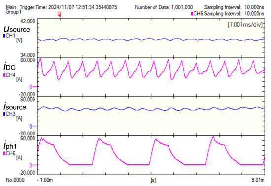
Figure 13.
Waveforms of usource, iDC, isource, and iph1, SRM for speed 4000 rpm, TL = 1 Nm, θdwell = 19° without DC/DC converter.
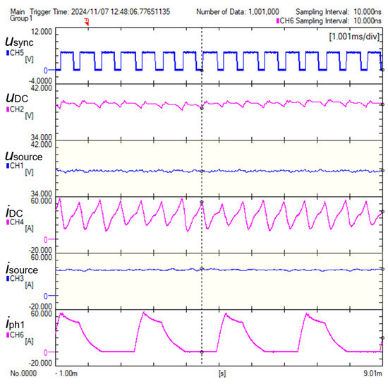
Figure 14.
Waveforms of usource, iDC, isource, and iph1, SRM for the speed of 4000 rpm, TL = 1 Nm, and θdwell = 19° with DC/DC converter.
The efficiency of the DC/DC converter was calculated from measurements with the Yokogawa power analyser, based on the measurement of the power drawn from the source and the power fed back to the DC/DC converter. The efficiency of the DC/DC converter for this operating point was about 97%. The efficiency of the DC/DC converter as a function of rotor speed under a torque load of 5 and 8 Nm is shown in Figure 15.
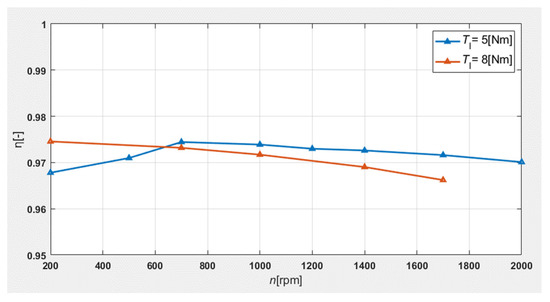
Figure 15.
Efficiency of the DC/DC converter as a function of rotor speed under a torque load of 5 and 8 Nm.
4.4. Dynamic Operating States of the SRM Drive
To check the behaviour of the SRM drive system with the proposed solution in dynamic states, tests during the SRM start-up and the load torque variation over time were performed. The SRM start-up was conducted for the two cases of the SRM power supply without and with the DC/DC converter, with the power source voltage, Usource = 38.5 V. Oscillograms from the SRM start-up are shown in Figure 16 (SDC/DC_on/off = on) and Figure 17 (SDC/DC_on/off = off). Figure 16 shows the waveforms of the power source voltage and current, as well as the SRM phase current and speed. By observing the source voltage and current waveforms, significant source current ripples and source voltage ripples, as a result of the current flow, can be seen. For comparison, Figure 17 shows the same waveforms for the DC/DC converter online, controlled by the authors’ proposed method. In this figure, the source current and voltage ripples were significantly reduced. There are ripples noticeable only up to the SRM speeds of around 200 rpm.
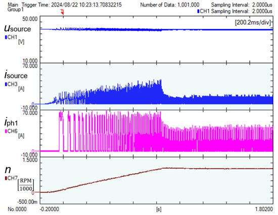
Figure 16.
Waveforms of usource, isource, SRM, iph1, and speed n during start-up from the classic system with the dynamometer off, θdwell = 20°.
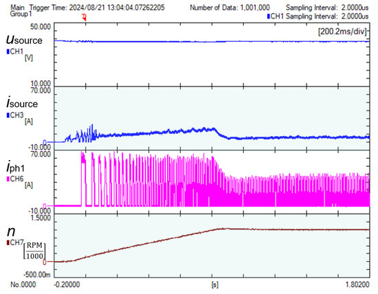
Figure 17.
Waveforms of usource, isource, SRM, iph1, and speed n during start-up from the proposed system with the dynamometer off, θdwell = 20°.
Figure 18 and Figure 19 show the behaviour of recorded parameters during a step change in load torque: 0 Nm→5 Nm→0 Nm with the speed stabilised at nref = 200 rpm in the system without a DC/DC converter (Figure 18) and with a DC/DC converter (Figure 19). The recorded waveforms indicate that using the DC/DC converter controlled by the proposed control algorithm leads to a noticeable reduction in the ripple of the current and voltage of the power source.
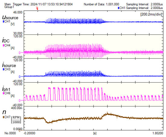
Figure 18.
Waveforms of usource, iDC, isource, and iph1, as well as n speed during load step change from 0 Nm to 5 Nm when operating without DC/DC converter, for θdwell = 19°, Usource = 38.5 V, and nref = 200 rpm.
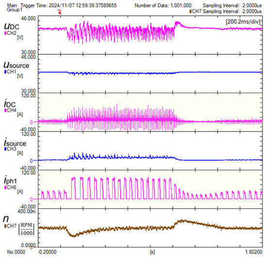
Figure 19.
Waveforms of uDC, usource, iDC, isource, and iph1, as well as n speed during load step change from 0 Nm to 5 Nm when operating with the proposed filtering system, for θdwell = 19°, Usource = 38.5 V, and nref = 200 rpm.
Figure 20 and Figure 21 show the oscillograms recorded during a change in motor speed from 1000 rpm to 2000 rpm and back to 1000 rpm with a load torque of TL = 1 Nm. Comparing the current and voltage waveforms of the power source when the drive operates without the DC/DC converter (Figure 20) and with the DC/DC converter (Figure 21), the effective operation of the DC/DC converter control algorithm can be observed.
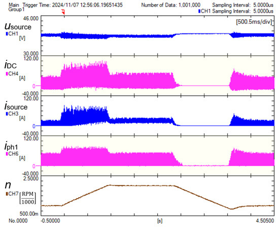
Figure 20.
Waveforms of usource, iDC, isource, iph1, and n speed when speed was changed from 1000 rpm to 2000 rpm and to 1000 rpm for TL = 1 Nm, θdwell = 19°, Usource = 38.5 V without DC/DC converter.
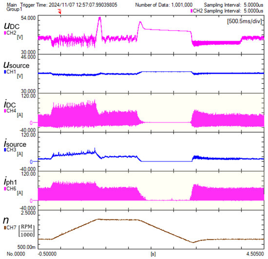
Figure 21.
Waveforms of usource, iDC, isource, iph1, and n speed when speed was changed from 1000 rpm to 2000 rpm and to 1000 rpm for TL = 1 Nm, θdwell = 19°, Usource = 38.5 V with DC/DC converter.
5. Conclusions
This work presents a solution to reduce the source current ripple for a switchable reluctance motor (SRM) drive. Source current ripple adversely affects the power source by introducing variable frequency voltage ripples and increasing losses in the power source. The proposed solution consists of a classic DC/DC boost converter connected in series with the SRM power supply. The key to reducing source current ripple was the proposed method of controlling the DC/DC converter. Simulation and laboratory tests of the SRM drive were performed to assess the effectiveness of the proposed solution. From the SRM drive tests, it was found that:
- -
- It is possible to effectively reduce the source current ripple over a wide speed range of the SRM by using a simple DC/DC boost converter integrated in series with the SRM power supply;
- -
- The proposed method of source current ripple reduction has a lower efficiency in the low rotor speed range, which means up to about 200 rpm for the SRM tested, it is possible to significantly reduce the rms source current and, thus, the losses in the power source.
The proposed solution also has drawbacks, which include:
- -
- Higher complexity and cost of the SRM control system,
- -
- Slight deterioration in the efficiency of the SRM power supply system due to the use of a DC/DC converter.
Author Contributions
Conceptualization, P.B.; methodology, M.D.; software, M.D. and P.B.; validation, M.D. and P.B.; formal analysis, M.D.; investigation, M.D.; resources, M.D. and P.B.; data curation, M.D.; writing—original draft preparation, P.B. and M.D.; writing—review and editing, P.B. and M.D.; visualisation, M.D.; supervision, P.B.; project administration, P.B.; funding acquisition, P.B. All authors have read and agreed to the published version of the manuscript.
Funding
This research received no external funding.
Data Availability Statement
The original contributions presented in the study are included in the article, further inquiries can be directed to the corresponding author.
Conflicts of Interest
The authors declare no conflicts of interest.
References
- Vermeer, W.; Mouli, G.R.C.; Bauer, P. Robust-Oriented Optimization of Switched Reluctance Motors Considering Manufacturing. IEEE Trans. Transp. Electr. 2022, 8, 2853–2861. [Google Scholar]
- Lan, Y.; Benomar, Y.; Deepak, K.; Aksoz, A.; El Baghdadi, M.; Bostanci, E.; Hegazy, O. Switched Reluctance Motors and Drive Systems for Electric Vehicle Powertrains: State of the Art Analysis and Future Trends. Energies 2021, 14, 2079. [Google Scholar] [CrossRef]
- Bogusz, P.; Korkosz, M.; Prokop, J. Current harmonics analysis as a method of electrical faults diagnostic in switched reluctance motors. In Proceedings of the 2007 IEEE International Symposium on Diagnostics for Electric Machines, Power Electronics and Drives, Cracow, Poland, 6–8 September 2007. [Google Scholar]
- Bogusz, P.; Korkosz, M.; Prokop, J.; Daraż, M. Analysis Performance of SRM Based on the Novel Dependent Torque Control Method. Energies 2021, 14, 8203. [Google Scholar] [CrossRef]
- Gundogmus, O.; Das, S.; Yasa, Y.; Elamin, M.; Sozer, Y.; Kutz, J.; Tylenda, J.; Wright, R.L. Acoustic Noise Mitigation in High Pole Count Switched Reluctance Machines Utilizing Skewing Method on Stator and Rotor Poles. IEEE Trans. Ind. Electron. 2022, 69, 5581–5593. [Google Scholar] [CrossRef]
- Wiguna, C.A.; Cai, Y.; Lilian, L.L.S.S.; Furqani, J.; Fujii, Y.; Kiyota, K.; Chiba, A. Vibration and Acoustic Noise Reduction in Switched Reluctance Motor by Selective Radial Force Harmonics Reduction. IEEE Open J. Ind. Appl. 2023, 4, 23–34. [Google Scholar] [CrossRef]
- Husain, M.E. Torque ripple minimization in switched reluctance motor drives by PWM current control. IEEE Trans. Power Electron. 1996, 11, 83–88. [Google Scholar] [CrossRef]
- Vujičić, V.P. Minimization of Torque Ripple and Copper Losses in Switched Reluctance Drive. IEEE Trans. Power Electron. 2012, 27, 388–399. [Google Scholar] [CrossRef]
- Jing, B.; Dang, X.; Liu, Z.; Ji, J. Torque Ripple Suppression of Switched Reluctance Motor with Reference Torque Online Correction. Machines 2023, 11, 179. [Google Scholar] [CrossRef]
- Kusumi, T.; Hara, T.; Umetani, K.; Hiraki, E. Phase-current waveform for switched reluctance motors to eliminate input-current ripple and torque ripple in low-power propulsion below magnetic saturation. IET Power Electron. 2020, 13, 3351–3359. [Google Scholar] [CrossRef]
- Bogusz, P. A switched reluctance motor control method limiting the maximum DC source current in the low-speed range. Bull. Pol. Acad. Sci. Tech. Sci. 2016, 64, 197–206. [Google Scholar] [CrossRef][Green Version]
- Han, X.; Lu, L.; Zheng, Y.; Feng, X.; Li, Z.; Li, J.; Ouyang, M. A review on the key issues of the lithium ion battery degradation among the whole life cycle. eTransportation 2019, 1, 100005. [Google Scholar] [CrossRef]
- Vermeer, W.; Mouli, G.R.C.; Bauer, P. A Comprehensive Review on the Characteristics and Modeling of Lithium-Ion Battery Aging. IEEE Trans. Trans. Electr. 2022, 8, 2205–2232. [Google Scholar] [CrossRef]
- Neuhaus, C.R.; Fuengwarodsakul, N.H.; De Doncker, R.W. Control Scheme for Switched Reluctance Drives with Minimized DC-Link Capacitance. IEEE Trans. Power Electron. 2008, 23, 2557–2564. [Google Scholar] [CrossRef]
- Yi, F.; Cai, W. Modeling, Control and Seamless Transition of Bi-directional Battery-Driven Switched Reluctance Motor/Generator Drive based on Integrated Multiport Power Converter for Electric Vehicle Applications. IEEE Trans. Power Electron. 2015, 31, 7099–7111. [Google Scholar] [CrossRef]
- Mohamadi, M.; Rashidi, A.; Nejad, S.M.S.; Ebrahimi, M. A Switched Reluctance Motor Drive Based on Quasi Z-Source Converter with Voltage Regulation and Power Factor Correction. IEEE Trans. Ind. Electron. 2017, 65, 8330–8339. [Google Scholar] [CrossRef]
- Zhang, H.; Zhang, Y. Recent Advances in DC-DC Converters for Electric Vehicles. In Proceedings of the 2023 International Conference on Materials Engineering, New Energy and Chemistry (MENEC 2023), Kuala Lumpur, Malaysia, 13–15 October 2023. [Google Scholar]
- Ismail, A.A.A.; Elnady, A. Advanced Drive System for DC Motor Using Multilevel DC/DC Buck Converter Circuit. IEEE Access 2019, 7, 54167–54178. [Google Scholar] [CrossRef]
- Hoseini, S.M.; Sadeghzadeh, S.M.; Beromi, Y.A. A new method for active power factor correction using a dual A new method for active power factor correction using a dual purpose inverter in a flyback converter. Turk. J. Electr. Eng. Comput. Sci. 2016, 24, 4736–4750. [Google Scholar] [CrossRef]
- Suppharangsan, W.; Wang, J. Switching technique for minimisation of DC-link capacitance in switched reluctance machine drives. IET Electr. Syst. Transp. 2015, 5, 185–193. [Google Scholar] [CrossRef][Green Version]
- Ghadbane, H.E.; Barkat, S.; Djerioui, A.; Houari, A.; Oproescu, M.; Bizon, N. Energy management of electric vehicle using a new strategy based on slap swarm optimization and differential flatness control. Sci. Rep. 2024, 14, 3629. [Google Scholar] [CrossRef]
- Cai, W.; Fan, Y.F. An Integrated Multiport Power Converter With Small Capacitance Requirement for Switched Reluctance Motor Drive. IEEE Trans. Power Electron. 2016, 31, 3016–3026. [Google Scholar] [CrossRef]
- Singh, B.; Anand, A. Power Factor Correction in Modified SEPIC Fed Switched Reluctance Motor Drives. IEEE Trans. Ind. Appl. 2018, 54, 4494–4505. [Google Scholar] [CrossRef]
Disclaimer/Publisher’s Note: The statements, opinions and data contained in all publications are solely those of the individual author(s) and contributor(s) and not of MDPI and/or the editor(s). MDPI and/or the editor(s) disclaim responsibility for any injury to people or property resulting from any ideas, methods, instructions or products referred to in the content. |
© 2024 by the authors. Licensee MDPI, Basel, Switzerland. This article is an open access article distributed under the terms and conditions of the Creative Commons Attribution (CC BY) license (https://creativecommons.org/licenses/by/4.0/).