Abstract
Climate change has had an impact on the reduction in river flows in many places, affecting the hydroelectric production of several power plants, and this, together with the reduction in the economic retribution for this type of generation in several countries, has meant a substantial reduction in the income of companies. To offset these economic losses, the aim is to improve production efficiency in hydroelectric power plants. Therefore, it is proposed to innovate, firstly, by using doubly fed asynchronous electrical machines, DFIG; secondly, by using new construction criteria in the power plants; and lastly, by proposing new control and regulation variables. This improves the performance of low-flow water turbines and increases their efficiency. As a practical example, a particular study is presented for the Arenas de Iguña hydroelectric power plant (Hidroiguña) located in Cantabria, Spain, which allows a technical evaluation of the proposed action to be carried out in order to draw the corresponding conclusions.
1. Introduction
The alteration of the natural water cycle and increasing droughts are caused by climate change, which is accelerated by human action [1]. In several cases, these changes will lead to spatial and temporal redistributions of water resources with different responses such as the alteration of river flows [2,3,4,5] where small climatic variations, sometimes insignificant, can result in significant changes in the availability and regularity of water in reservoirs [6]. At the same time, human action modifies watercourses and river basins so the demand for drinking water, irrigation for agriculture, and other uses are increasing [7,8,9,10].
The rising evolution of global temperatures (averages, maximums, and minimums) experienced in the last few decades [3,4] causes the atmosphere to capture more humidity, and therefore increases the evaporation of water and the evapotranspiration of plants [11]. In addition, future forecasts indicate that the trend will continue to increase [3,10]. The increase in atmospheric humidity leads to an increase in precipitation virulence and an increase in the difficulty of storing it in reservoirs. On the other hand, the alteration of the water cycle [12] will modify precipitation by increasing soil moisture. This will impact runoff, evaporation, atmospheric vapor, and water temperature, leading to more extreme conditions and phenomena [11].
Hydropower is currently one of the world’s largest producers of renewable energy, accounting for more than 43% of low-carbon energy and 16% of the total electricity budget [4,5,13]; however, the hydroelectric production of several power plants has been negatively impacted by the change in river flows [2,4,6,10,14], depending on their location [5,15], sometimes increasing, sometimes decreasing. For example, a study of the impact of climate change on hydropower generation in Croatia indicates that a reduction of more than 10% in electricity generation could be expected after 2050 in the IPCC A2 scenario [16].
Another important alteration in the river basins is the increase in flow in times of excess and decrease in times of low flow [15]. In the future, it is expected that 80% of the existing basins will suffer seasonal alterations in their flow [2].
Unless the system is designed for the prevailing environmental conditions, any hydropower infrastructure project with several decades of useful life is vulnerable to the potential hazards of climate change [2]. Consequently, in several cases, it is necessary to re-evaluate the design and operating parameters of previously constructed hydropower installations [5,10], as the initial sizing of the turbine or machinery may have become obsolete.
To improve the performance of hydroelectric generation, several authors propose the incorporation of new electrical machines for generation, mainly the doubly fed asynchronous generator, DFIG, highlighting an improved efficiency in the generation/pumping mode with respect to the change in the water load [17] and a reduction in the energy used [18]. Other studies show satisfactory results in its use compared to the synchronous technologies used [19].
On the other hand, other authors present as a solution to improve production the incorporation of more variables in the turbine regulation systems [20].
However, these studies have not taken into account the problem of reduced river flows due to climate change and increased demand.
Therefore, this article focuses on the productive improvement of hydroelectric power plants with low river flows in order to adapt to the current situation and improve productive performance. In this way, firstly, DFIG technology is studied; secondly, new design parameters in the construction of the power plants are evaluated; and finally, the possible incorporation of the variation experienced in the water jump as a new variable in the regulation of the electric machine is proposed.
Afterwards, we discuss the productive impact and the improvement in the use of the existing flows of a flowing-water plant with a synchronous machine where seasonal variations in flow have been experienced. Then, the impact of a new design of the plant on power generation will be proposed.
2. Materials and Methods
2.1. Premises for the Design and Operation of Existing Hydroelectric Power Plants
The design of a hydroelectric power plant requires preparing the machinery to operate most days of the year and also to be able to act as a turbine for the largest flow variation with the highest possible turbine performance. In the 1940s and 1950s, engineers sized turbines to operate at reduced flow rates for most of the year, but, on the other hand, prepared facilities to incorporate a new generation group if necessary. The power ratio between both groups was 1 to 3, respectively, and in this way, it also adapted the generation to greater flow variation. Afterwards, the engineers chose to install only one generation group for higher flow rates and without the possibility of incorporating new groups, which caused in several cases a reduction in working days and increase in working days that the group worked with low productive performances.
For flowing-water power plants with an installed capacity of less than 5 MW, asynchronous generators were mainly used. These types of generators, also known as fixed-speed ones, have been widely used in low-power-generation equipment, both mini-hydroelectric plants and small wind turbines, due to the following advantages: simpler and more robust manufacturing, no need for complex maintenance, without the need for additional electrical circuits, and without voltage regulation, because it is imposed by the external network.
Asynchronous generators in steady state operation have a narrow range of rotor speed, which is the mobile part of the machine, in their torque–speed characteristic curve (M-n). Between the torque, zero, and maximum values, the speed range is very small, which is why they are called fixed-speed machines, because, for wide variations in torque, they undergo a reduced speed change, provided they operate in the stable working area. This wide variation in torque with a narrow variation in speed was admitted as a very positive feature to apply to the operation of generating machines where the torque could undergo variations, such as in hydroelectric plants whose turbine rotation depends on the flow or in wind turbines whose rotation of the blades depends on the wind. This meant that, for variations in torque imposed by flow or wind, it did not affect the speed of the electric machine.
2.2. Characteristics of the Hydroelectric Plant Under Study
The Arenas de Iguña hydroelectric power plant is located on the Besaya River in the municipal district of Arenas de Iguña, province of Cantabria, Spain (Figure 1). Its origin comes from one of the oldest hydroelectric stations in Arenas de Iguña used by the flour mill of La Serna de Iguña. It was later rebuilt on the overflow of the old station and named Hidroiguña. The rehabilitated plant was connected in 2009. The main structures, such as the dam, were maintained during the rehabilitation. The condition of the construction was also improved, and new equipment was installed.
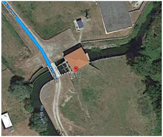
Figure 1.
Location of hydroelectric power station Arenas de Iguña, according to coordinates (43.178730, −4.045281).
The plant is of the type of flowing water with a net jump of 6.6 m. The ecological flow rate during low flow periods is 0.8 m3/s and during high flow periods, it is 1.6 m3/s.
The main equipment installed at the plant is described below: the hydraulic turbine and the electric machine.
The hydraulic turbine is a semi-Kaplan-type turbine (Kaplan with blade regulation). Its characteristics are shown in Table 1 and it has a technical minimum of 30% of the turbine flow, Q [21].

Table 1.
Technical specifications of the installed turbine [21].
The Kaplan and propeller turbine, both axial, are suitable for small jumps and rotational speeds. The higher the jump, the lower the specific speed (design magnitude of hydraulic turbines) to avoid the risk of cavitation and the corresponding negative impact. Generally, hydraulic turbines are designed to operate at a constant speed around an optimum work point characterized by the head, discharge, and opening of the guide vane [22].
Figure 2 shows the performance curve according to the mechanical power supplied to the shaft, Pm, corresponding to the semi-Kaplan turbine installed in the power plant, where the output of the shaft is presented. The net jump, Hn, and the shaft rotational speed, n, are considered constants. The general consensus is that hydraulic turbines should not operate below 80% efficiency [23].
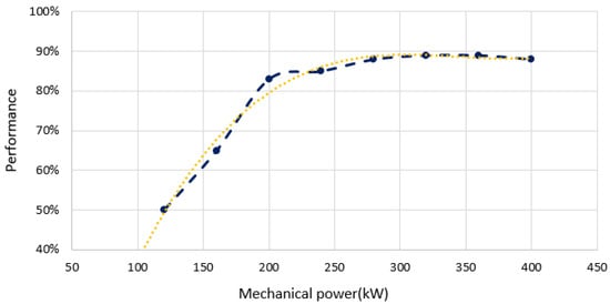
Figure 2.
Performance vs. mechanical power of turbine shaft [21].
As the net jump and the shaft rotational speed are constant, the curve of the performance against the turbinable flow transmitted to the shaft is similar to the one shown in Figure 2. Optimum performance is obtained on this curve at 6.3 m3/s, with a deviation of ±0.3% (According to the yellow curve in Figure 2).
As both curves, the performance according to the mechanical power supplied to the shaft and the flow rate, were designed with a constant rotational speed and net jump, it is assumed that the variation experienced in the performance of the correct operation of the turbine is caused by variations in the shaft torque, M, according to Expression (1), where varying the power transmitted to the shaft must vary the corresponding torque.
The generator is MARELLI (Arzignano, Italy), type C3G 400 LB14, 400 kW a 428 rpm, 400 V, IP-23, IC-01, F/B, V1 type, vertical 14 poles.
2.3. Problems and Solutions Presented
The generator in the plant is currently experiencing multiple problems, which the promoters initially attributed to variations in the available river flow. As the dam has a relatively pronounced width and the jump variation is very similar upstream and downstream by the orography of the land, initially, the analysis of the influence of the jump in production was discarded and the study focuses on the equipment used.
The characteristic point of operation of the turbines corresponds to specific values for the water jump and flow rate and with a certain opening of the blades. For jumps greater or smaller than the design, the turbine will not work at its optimum design point and may suffer a significant loss of efficiency at any opening of the guide vane. Water heads operating outside the design may lead to changes in the velocity of the entry and exit flow. At the entry of the rotor blades, impact losses can occur and flow instabilities at the exit cause efficiency to decrease. Also, the position of the guide vane has a direct effect on the input speed with its negative impact [22].
On the other hand, as the asynchronous generators are directly connected to the turbine shaft, and operate with a narrow speed range, corresponding to the head and flow rate with a respective vane opening, if they operate at higher or lower jumps than the design and their corresponding flow rates, the electric machine shaft speed may experience variations that can also be extrapolated to the correct operation of the generator [24]. Productive efficiency is lost in the turbine, and, at the same time, there may be a significant variation in the required speed, affecting the suitable operation of the generator, issues that coincide with the problems presented by the promoter of the mini-hydroelectric plant where the study is being carried out.
Initially, the possibility of connecting a frequency converter to the output of the asynchronous generator was considered, to adapt the rotational signal of the electrical machine to that imposed by the turbine without affecting the working torque, but the desired objectives were not achieved. This is possibly because the working variables of the converter were not directly related to the variables that affect, upstream, the rotation of the hydraulic turbine. In addition, being a squirrel cage asynchronous generator, a frequency converter with a signal processing capacity of 100% of the generated power was required, which made the necessary investment more expensive without having the solution assured by the supplier.
Therefore, with the observations and analysis of the equipment carried out, it is proposed to adapt the rotational speed of the electric machine to the variable speed of the turbine shaft. Furthermore, a possible modification in the design of the installation is evaluated.
2.4. DFIG Technology in Hydroelectric Power Plants
At present, given the variations in river flows due to climate change or increased demand, it may happen that, if the river flow has decreased over time or varies according to the seasons, i.e., increases in times of high flow or decreases in dry seasons, it is interesting to size the hydroelectric power plant to cover the widest range of flows with a high leeway with good performance. The possibility of using DFIG generators in hydroelectric generation, widely applied in wind turbines, improves the productive efficiency for flow rates below the nominal flow rate, being able to increase the production days with reduced flow rates with an acceptable efficiency of the group. In this case, the conservation of the shaft rotation speed will not be indispensable and may provide greater relevance to the maintenance of the shaft torque that can ensure a performance close to the optimum in the hydraulic turbine for different mechanical powers delivered to the shaft in addition to the design power.
Figure 3 shows the diagram of a hydroelectric power plant with DFIG technology with the frequency converter connected between the grid and the rotor. The converter is responsible for adapting the armature frequency, f2, to the variations in machine shaft speed, n, imposed by the flow rate, to obtain a constant inductor frequency, f1.
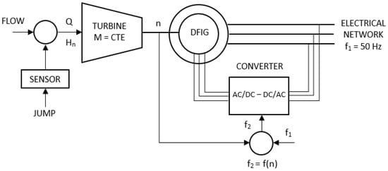
Figure 3.
Diagram of proposed installation.
On the other hand, as advantages over squirrel cage asynchronous generators or synchronous generators, both connected to the grid with a frequency converter, it should be noted that the power passing through the converter is between 20 and 30% of the nominal power, depending only on the speed variation margin and reactive power requirements [25]. Therefore, the frequency converter, bidirectional, has a maximum dimension of only 30% of the nominal power of the generating electrical machine, which reduces its economic cost and reduces the associated losses. In addition, the equipment allows voltage fluctuations at the point of connection to the grid to be reduced and allows independent control of the active and reactive power delivered to the grid [25]. An example of the application of DFIG technology in hydroelectric plants can be found in the pilot power plant of Compuerto (Spain), where the rotor of the 10 MW generator is powered by an electronic converter [22], finding significant improvements in the performance of the power system and even a greater margin of stability [19].
By changing the group rotation speed, it is possible to better adapt to the operating conditions of the plant and improve the overall performance of the plant, especially in small-jump plants. In addition, the risk of cavitation and pressure fluctuations in the discharge pipe is reduced and the operating limits of the power plant can be significantly extended [24].
Fraile-Ardanuy et al. [19] evaluated the advantages of applying variable-speed technology over fixed speed in hydroelectric generation in terms of the turbine, generator, and control system. The results obtained by simulating the operation of a flowing-water mini-hydroelectric plant, for a period of 33 consecutive years, considering the same amount of water in both cases, estimated a gain of 6.5% of average annual energy production and other environmental benefits presented by other authors [24,25]. Other studies confirm the results showing that, in general, with a variable speed, a significant increase in production is expected and, in many cases, a reduction in the area flooded by the reservoir, without reducing the energy generated at the plant and causing less environmental impact [24].
In order to make a critical assessment, the following possibilities are considered in the supposed mini-hydroelectric plant with incorporated DFIG technology and jump height meters installed and with the same power performance as the installed equipment:
- Flow change, Q, depending on resource availability.
- Torque variation, M, and speed, n, by turbine blades.
- Awareness of the net jump value available, Hn.
Therefore, the following variables are considered: Hn, M, n, Q y ηt.
The hydraulic power obtained on the turbine shaft, PH, is calculated with Expression (2) where is the density of the water and ηt is the turbine performance:
As the hydraulic power on the turbine shaft is equal to the mechanical power offered to the shaft, Pm (3), the above expression can be related to the torque value, M, and the speed of the shaft in question, n, and when replaced, the following is obtained (4):
Considering equality (4), a series of premises and objectives will be realized and then applied to the supposedly installed complex.
- The first thing is that now it is not necessary to keep constant the shaft speed because through the installed converter, you can vary the frequency of the inductor to continue obtaining the frequency of the inductor to 50 Hz, which is the frequency of the grid.
- In view of the turbine performance curve as a function of the mechanical power transmitted to the shaft (Figure 2), maintaining as constant the rotational speed and the net jump, it is understood that part of the variation experienced in the performance of the correct operation of the turbine is caused by variations in the shaft torque, M.
Therefore, if it is possible that the speed of rotation varies, it can be considered to keep constant the mechanical torque to the shaft, for different mechanical powers delivered to the shaft. Even with certain limitations, this provides a significant advantage: if the torque is kept constant, the turbine operation can be maintained close to the optimum.
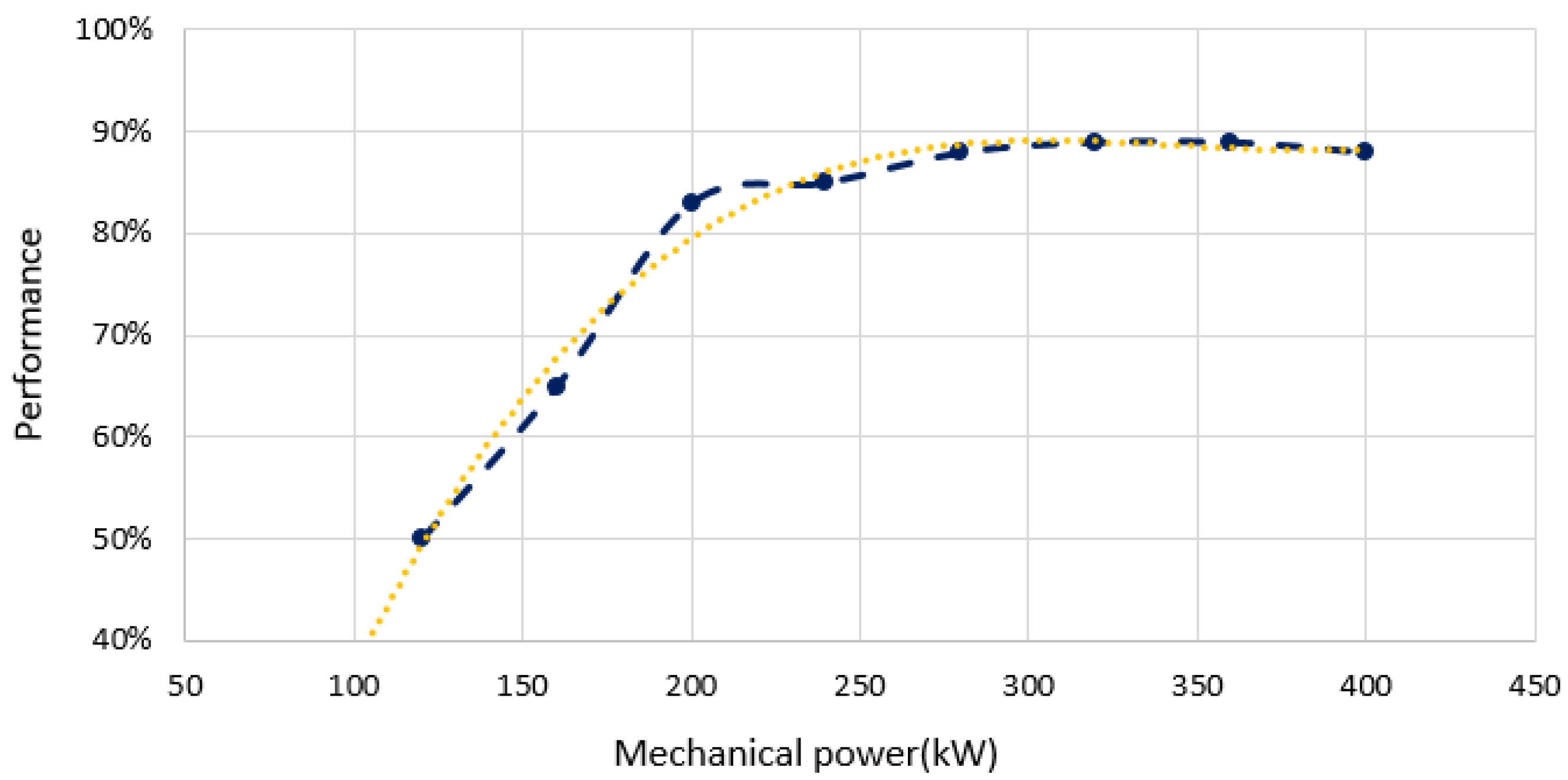
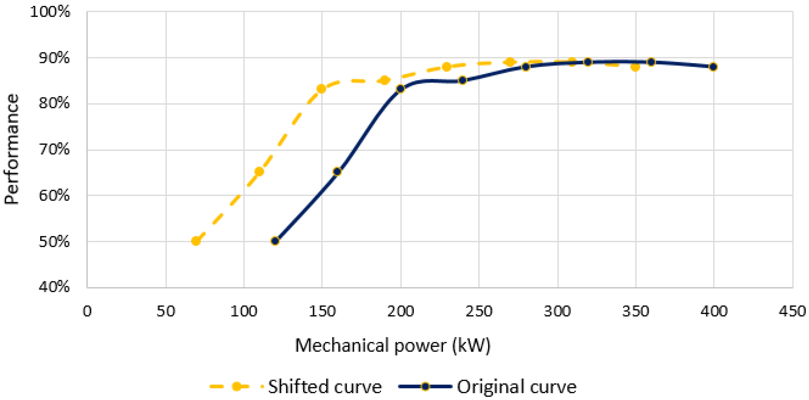
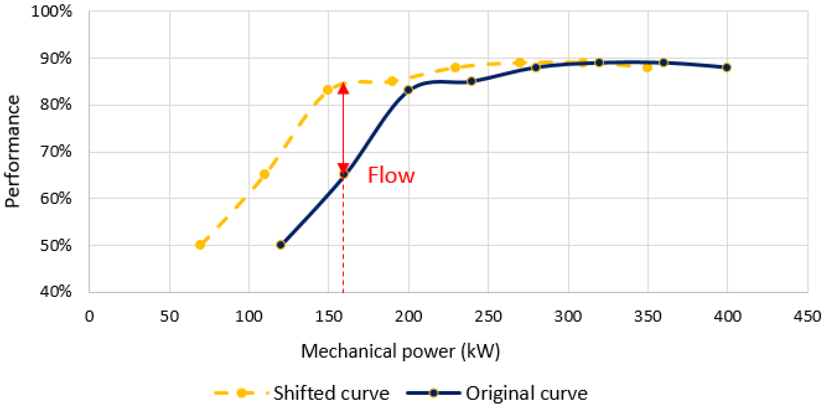
In addition, as seen in Figure 4, the performance curve based on the mechanical power delivered to the shaft could be shifted to both sides and provide the optimum operating performance for other powers.
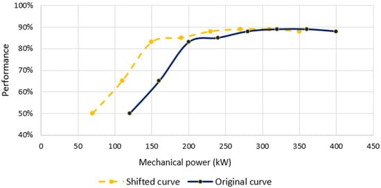
Figure 4.
Shift in performance curve vs. mechanical shaft power at constant torque.
The objective is to maintain an optimal performance of the hydraulic turbine with a constant torque by varying the speed of rotation with an adequate regulation of the rotation of the turbine blades. In order to maintain the turbine performance at its optimum value, it is possible to reduce the required hydraulic power and, therefore, the required water flow rate for a mechanical power delivered to the shaft other than the reference. This question is very interesting because, from an environmental point of view and working in flows close to the technical minimum, when the necessary flow is reduced, an increase in production is possible.
In Expression (2), it is observed that many of the parameters are known so that a certain flow rate can be evaluated to obtain a certain power with an efficiency very close to the optimum of the turbine without affecting the correct operation of the rest of the equipment. The generator will always be supplied with the right operating torque.
2.5. Application of DFIG Technology to Standard Plant
Using the known values of the equipment of the mini-hydroelectric plant of Arenas de Iguña to obtain its optimal performance according to the data offered by the manufacturer, the torque value can be obtained by expressing the hydraulic power and power supplied to the shaft. The following values are considered:
- Net jump, Hn = 6.6 m.
- Optimum performance of the turbine, ηt = 0.89.
- 90% nominal flow rate, Q = 6.3 m3/s.
- Turbine rotation speed, n = 300 r.p.m.
- Gravitational constant, g = 9.81 m/s2.
- Water density at 1 atm and 20 °C, ρ = 998 kg/m3.
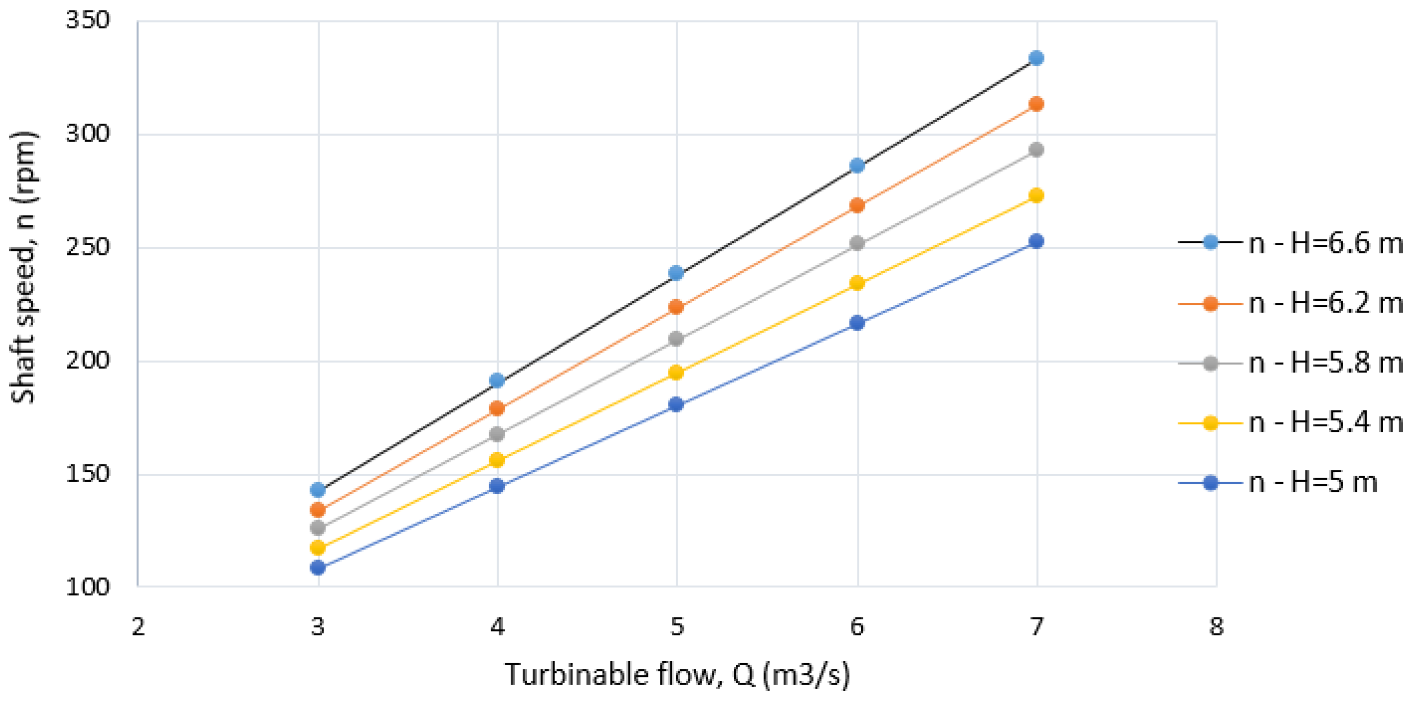
By substituting these values in Expression (4), a value of the torque delivered to the axis, M, of 11,532.5 N is obtained. In this way, the performance and the torque can be established as fixed work values. Then, we consider Expression (5) in which, for a given net jump, the relationship between the shaft speed and the flow rate used is provided. Thus, considering that the net jump varies between 6.6 and 5 m in steps of 0.4 m, the curves of Figure 5 are obtained.
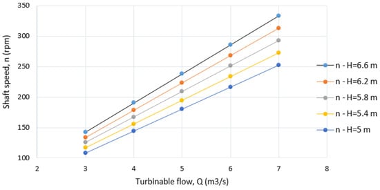
Figure 5.
Speed–flow curves for several net jumps.
Thus, for a flowing-water hydroelectric plant with a certain net jump, the flow rate used will keep the mechanical torque constant and, in turn, will produce a certain mechanical power to the shaft with close to optimal performance. In the case of a regulating hydroelectric plant with a certain net jump and a necessary electrical power, the flow rate may be adjusted according to the necessary turns, provided that the torque remains cons-tant. In this way, a relation of variables is obtained to perform the inputs of the electronic system, including the converter, which regulates the generation system, adapting it to the possibilities of the power plant and to monthly, weekly, and even lower-type regulations.
With the considerations made, keeping the torque constant and for a certain jump, the performance curve could be moved with respect to the power in the way described in Figure 4 above.
For a power plant with flow regulation, it would mean a flow saving for a certain mechanical power delivered to the shaft, since the performance improvement has a direct extrapolation to the saving of the flow used according to Expression (4) and considering an optimal performance maintenance. According to the example in Figure 6, for the same characteristics of the study turbine and for a power transmitted to the axis of 170 kW, the savings of the flow would be close to 20%.

Figure 6.
Saved flow by shifting the performance curve vs. mechanical power.
In the case of a flowing-water plant with no possibility of a significant storing of water, as is the case and where the flow is imposed by the availability of the resource, if operation below 80% of turbine performance is not recommended and fixed-speed technology with variable torque is used as a must, below approximately a flow rate of 3.4 m3/s, the system cannot be started with the corresponding loss of turbinable flow.
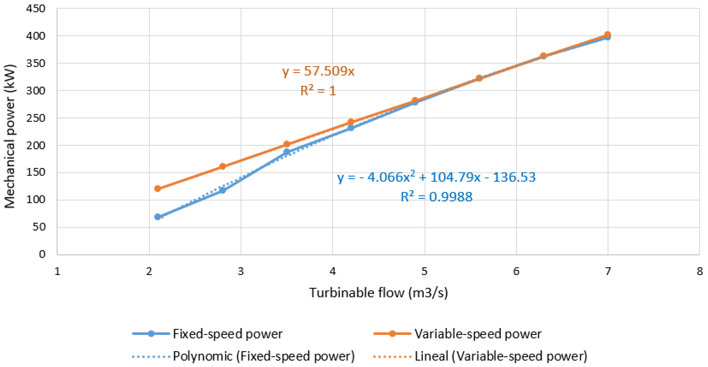
With the application of variable speed, the performance improvement would become a productive improvement as it would become an increase in its generation capacity (Figure 7).
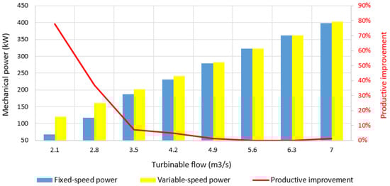
Figure 7.
Mechanical power by technology and percentage of productive improvement.
In the same way, the work of the turbine would also be used in those areas not re-commended to work because it has a turbine performance below 80%, that is, in the example for mechanical powers delivered to the shaft below approximately 180 kW and the use of the corresponding flow that cannot be retained. Figure 7 shows that, as the turbinable flow decreases, the increase in production capacity is more significant (see Table 2), with two inflection points corresponding to 70% and 50% of the turbinable flow.
Table 2.
Experienced margins of improvement according to flow ranges.
With these data, what is observed is that there is a very significant increase in the flows close to the technical minimum of the turbine. This section goes from the technical minimum to the most relevant inflection point that is close to 80% performance. This percentage of increase in production capacity would be obtained for any jump but would significantly affect production, requiring greater flow for the same mechanical power on the shaft.
- Considering only the performance above 80% of the fixed-speed curve, a productive improvement of 1.7% would be achieved.
- If the proposed technology is allowed to operate, a production improvement of 21.12% could be achieved in the working areas with a greater probability of the resource, since it requires a lower flow rate, and there would be a significant increase in economic benefits.
With this, it is clear that the working area where action is of the most interest is that close to the flow of the technical minimum (see Figure 8).
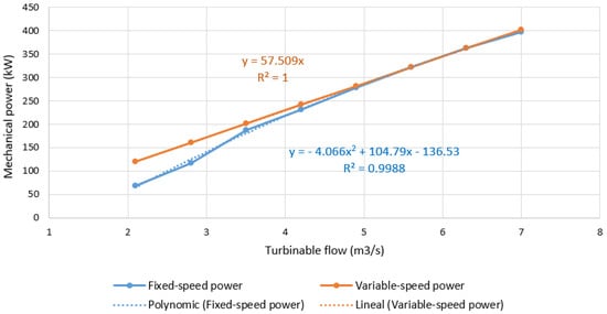
Figure 8.
Productive comparison between fixed- and variable-speed technologies.
2.6. The Productive Analysis of the Change to DFIG Technology at the Plant
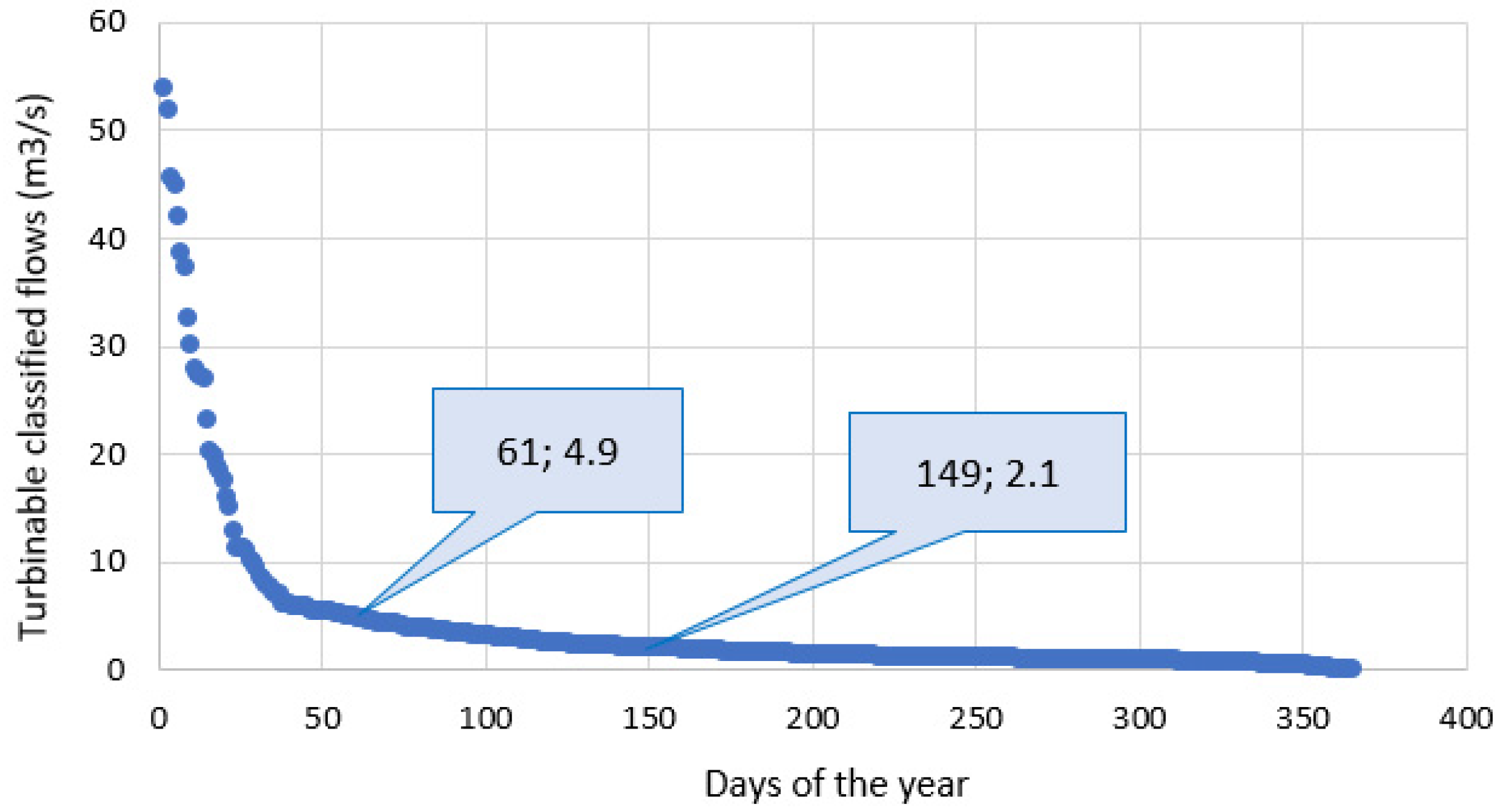
For the analysis of the Arenas de Iguña hydroelectric plant, where there are many days that the plant is out of operation due to the reduced flow rate, and significant differences between the maximum and minimum values of the turbinable flow are experienced, an average value of the turbinable flow of recent years is considered. This gives the flow curve as a function of the turbinable flow (Figure 9).
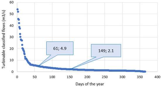
Figure 9.
Turbinable classified flow curve.
The hydroelectric power station is at a low altitude (height of 185 m). The basin area is approximately 200 km2 (total basin area of the river: 482 km2), which means that flows are not homogeneous throughout the year.
For the study, there are flow records from the power station obtained every five minutes for 10 years. In addition, there are data from a nearby station (Torrelavega) with 22 complete and 4 incomplete years.
The technical minimum of the turbine is 2.1 m3/s. The figure shows that only the average daily flow rate of 144 days per year is higher than the technical minimum; therefore, it is necessary to achieve more efficiency in operation.
In addition, there is a significant period of 88 days (149–61) where the flow rate is between 30% and 70% of the turbine flow rate and where a significant improvement in performance can be obtained, according to Table 2.
In conclusion, from the turbinable flow data (Figure 9) and applying the DFIG technology to the current electric machine, an annual productive improvement of the power plant of 6.1% is obtained.
2.7. Modification or Possible Extension of Turbine Groups
In the 1940s and 1950s, the hydroelectric production of a plant was divided into several groups. This option will be considered when incorporating a turbine for reduced flows to the existing plant where DFIG technology has been incorporated.
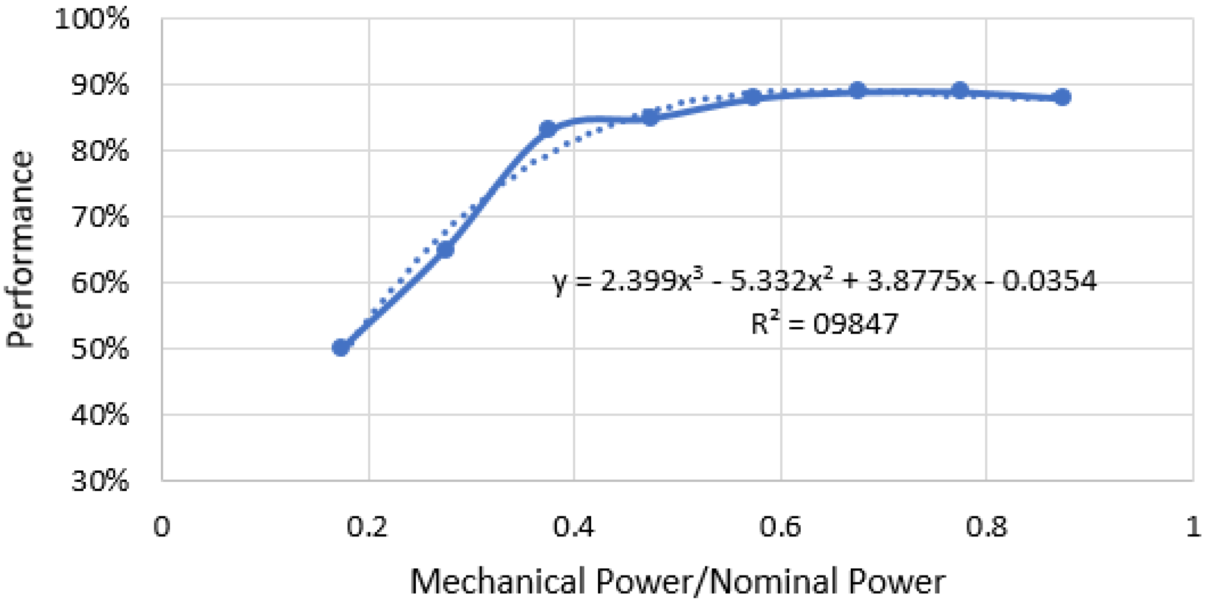
For the study, the curve representing the yield will be modified according to the mechanical power delivered to the shaft in Figure 6. Instead of considering this power, the ratio of the transmitted power to the axis divided by the corresponding nominal power is considered. In this way, a curve of a generic character is obtained that allows the study of the different expansion possibilities, evaluating different nominal power magnitudes for the same type of turbine. Thus, the curve of Figure 10 is obtained.
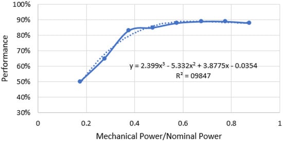
Figure 10.
Performance vs. mechanical power between nominal powers.
From the existing plant with integrated DFIG technology, it is necessary to expand the existing plant with a group for small flows of 2 m3/s and in also using DFIG technology, an annual production increase of 40.15% would be obtained.
On the other hand, it is stressed that the optimal proportionality between the gene-rating groups that are installed in a hydroelectric power plant must be made according to the curve of classified turbinable flows.
3. Results
With special emphasis on the lines developed in the work, the use of DFIG techno-logy provides numerous advantages to the generation system of a hydraulic power plant, among which the following have been detailed:
- The increase in the productive capacity of the generation system in most of its range of work causes productive improvements that can reach 21.12% in reduced flows. This means that annual production increases of more than 6% are obtained in the case presented and similar studies.
- Especially in the case of flowing-water power plants, the possible use of the power plant below the current limitations provides a greater production period by allowing working with flows that were previously impossible.
An extension of the service life of the electric machine would also be obtained for a regulating hydroelectric plant with a certain capacity of reservoir water, regulating the hydroelectric plant because the flow savings could be extrapolated to storage for the reservoir of the water saved and, therefore, greater landscape homogeneity throughout the year, reducing the times of the year of low flow, something very important for the reduction in the landscape impact in the area.
Finally, it is really interesting to use several generation groups to cover most of the turbinable flow and significantly increase the power generation, allowing the plant to increase days of operation.
4. Discussion
The results obtained are very relevant in those situations that, either due to a design error or changes in the magnitude of the river flow, the turbines are oversized, or you want to work close to their technical minimum or extend to the maximum the field of work while maintaining performance above 80%.
The productivity improvements presented by other authors are verified but, in turn, a comparative methodology is introduced to determine the different possibilities when sizing the generation group in the design and the future, given the significant difference between maximum and minimum values of turbinable flow in the plant, an issue that tends to increase with climate change.
As the main limitation of the study, it is considered necessary to incorporate the ana-lysis of the forces experienced in the turbine blades to maintain the constant torque without negatively influencing the vector triangle at the turbine exit. It would be appropriate to define different working curves of the equipment proposed in the studied power plant in order to find out in detail the operating limits, given the variables in play and their possible influence and impact on the correct functioning of the system.
The main future line of research is to test the shift in the mechanical power vs. efficiency curve in a laboratory or in a power plant.
Another future line of research we present is the introduction of a jump in the regulation of the electric machine to improve productivity. This will be feasible in reservoir plants or where the upstream jump and downstream jump have sufficient variation. The analysis or quantification of the minimum jump variation required will also be a matter of study.
Author Contributions
Conceptualization and methodology, F.J.B.; validation and investigation, F.J.B., J.R.A. and C.R.; resources and data curation, F.J.B. and J.R.A.; writing—original draft preparation, F.J.B., J.R.A. and C.R.; writing—review and editing, F.J.B.; visualization and supervision, F.J.B.; project administration, J.R.A.; funding acquisition, F.J.B. All authors have read and agreed to the published version of the manuscript.
Funding
This research has not received external funding and the APC has been funded by ANJACA SLU (Supplies and Engineering), Zoco Gran Santander, 166, 39011 Santander, Cantabria, Spain.
Data Availability Statement
Regarding the flow data used for the study, the records of the plant itself have been provided exclusively for this article and therefore only the results are shown. The river records are available on https://ceh.cedex.es/anuarioaforos/afo/estaf-datos.asp?indroea=1237 (accessed on 10 July 2024).
Acknowledgments
The study of this article was supported by the company Hidroiguña, S.L., which allowed us to collect data from their equipment. The authors would like to dedicate this document to Tomás Fernández Gutiérrez and José Manuel Fernández Campa, owners of Hidroiguña, S.L., for their interested collaboration.
Conflicts of Interest
The authors declare no conflicts of interest. The funders had no role in the design of the study; in the collection, analyses, or interpretation of data; in the writing of the manuscript; or in the decision to publish the results.
References
- Vicente-Serrano, S.M.; Tomas-Burguera, M.; Beguería, S.; Reig, F.; Latorre, B.; Peña-Gallardo, M.; Luna, M.Y.; Morata, A.; González-Hidalgo, J.C. A High Resolution Dataset of Drought Indices for Spain. Data 2017, 2, 22. [Google Scholar] [CrossRef]
- Vinod, C.; Tirupati, B.; Ram, B. Climate change impact assessment on hydropower generation using multi-model climate ensemble. Renew. Energy 2017, 109, 510–517. [Google Scholar]
- Arnell, N.W.; Gosling, S.N. The impacts of climate change on river flow regimes at the global scale. J. Hydrol. 2013, 486, 351–364. [Google Scholar] [CrossRef]
- Nonki, R.M.; Amoussou, E.; Lennard, C.J.; Lenouo, A.; Tshimanga, R.M.; Houndenou, C. Quantification and allocation of uncertainties of climate change impacts on hydropower potential under 1.5 °C and 2.0 °C global warming levels in the headwaters of the Benue River Basin, Cameroon. Renew. Energy 2023, 215, 118979. [Google Scholar] [CrossRef]
- Jjunju, E.; Killingtveit, Å.; Hamududu, B. 6.13—Hydropower and Climate Change. In Comprehensive Renewable Energy, 2nd ed.; Letcher, T.M., Ed.; Elsevier: Amsterdam, The Netherlands, 2022; pp. 259–283. [Google Scholar]
- Wang, H.; Xiao, W.; Wang, Y.; Zhao, Y.; Lu, F.; Yang, M.; Hou, B.; Yang, H. Assessment of the impact of climate change on hydropower potential in the Nanliujiang river basin of China. Energy 2019, 167, 950–959. [Google Scholar] [CrossRef]
- Schaefli, B. Projecting hydropower production under future climates: A guide for decision-makers and modelers to interpret and design climate change impact assessments. WIREs Water 2015, 2, 271–289. [Google Scholar] [CrossRef]
- Risal, A.; Parajuli, P.B.; Dash, P.; Ouyang, Y.; Linhoss, A. Sensitivity of hydrology and water quality to variation in land use and land cover data. Agric. Water Manag. 2020, 241, 106366. [Google Scholar] [CrossRef]
- Harrigan, S.; Cloke, H.; Pappenberger, F. Innovación en la Predicción Hidrológica Mundial Mediante el Enfoque del Sistema Tierra; Organización Meteorológica Mundial: Geneva, Switzerland, 2020; Available online: https://repositorio.aemet.es/bitstream/20.500.11765/12652/1/BolOMM-69_1%284%29.pdf (accessed on 10 July 2024).
- Molerio-León, L.F. Reingeniería Geológica, Hidrológica e Hidráulica del Cambio Climático: Situación y Perspectivas. Cub@ Medio Ambiente Desarro. 2022, 22. Available online: https://cmad.ama.cu/index.php/cmad/article/download/317/685 (accessed on 10 May 2024).
- Ebtehaj, I.; Bonakdari, H. A reliable hybrid outlier robust non-tuned rapid machine learning model for multi-step ahead flood forecasting in Quebec, Canada. J. Hydrol. 2022, 614, 128592. [Google Scholar] [CrossRef]
- Ostad-Ali-Askar, K.; Su, R.; Liu, L. Water resources and climate change. J. Water Clim. Chang. 2018, 9, 239. [Google Scholar] [CrossRef]
- Malhan, P.; Mittal, M. A novel ensemble model for long-term forecasting of wind and hydro power generation. Energy Convers. Manag. 2022, 251, 114983. [Google Scholar] [CrossRef]
- Chandramowli, S.N.; Felder, F.A. Impact of climate change on electricity systems and markets—A review of models and forecasts. Sustain. Energy Technol. Assess. 2014, 5, 62–74. [Google Scholar] [CrossRef]
- Krysanova, V.; Dickens, C.; Timmerman, J.; Varela-Ortega, C.; Schlüter, M.; Roest, K.; Huntjens, P.; Jaspers, F.; Buiteveld, H.; Moreno, E.; et al. Cross-comparison of climate change adaptation strategies across large river basins in Europe, Africa and Asia. Water Resour. Manag. 2010, 24, 4121–4160. [Google Scholar] [CrossRef]
- Pašičko, R.; Branković, Č.; Šimić, Z. Assessment of climate change impacts on energy generation from renewable sources in Croatia. Renew. Energy 2012, 46, 224–231. [Google Scholar] [CrossRef]
- Joseph, A.; Chelliah, T.R.; Lee, K.B. Multi-channel VSI fed large variable speed asynchronous hydro-condenser: Fault analysis, fault diagnosis and fault tolerant control. IET Renew. Power Gener. 2019, 13, 438–450. [Google Scholar] [CrossRef]
- Singh, R.R.; Baranidharan, M.; Subramaniam, U.; Bhaskar, M.S.; Rangarajan, S.S.; Abdelsalam, H.A.; Collins, E.R.; Senjyu, T. An energy-efficient start-up strategy for large variable speed hydro pump turbine equipped with doubly fed asynchronous machine. Energies 2022, 15, 3138. [Google Scholar] [CrossRef]
- Fraile-Ardanuy, J.; Wilhelmi, J.R.; Fraile-Mora, J.J.; Pérez, J.I. Variable-speed hydro generation: Operational aspects and control. IEEE Trans. Energy Convers. 2006, 21, 569–574. [Google Scholar] [CrossRef]
- Liu, J.; Xu, B.; Chen, D.; Li, J.; Gao, X.; Liu, G. Grid-connection analysis of hydro-turbine generator unit with stochastic disturbance. IET Renew. Power Gener. 2019, 13, 500–509. [Google Scholar] [CrossRef]
- Talleres, J. Vilá, Servicios Mecánicos. Polígono Industrial de Malolles, c/Masles de Roda, 1, 08500 VIC, Barcelona. Available online: http://www.tjvila.com/ (accessed on 10 July 2024).
- Heckelsmueller, G.P. Application of variable speed operation on Francis turbines. Ing. Investig. 2015, 35, 12–16. [Google Scholar] [CrossRef]
- Cárdenas Rojas, F.E. Técnicas para Lograr el Óptimo de la Característica de Generación de una Central Hidroeléctrica con Variación de Velocidad. 2010. Available online: https://repositorio.uncp.edu.pe/handle/20.500.12894/3581 (accessed on 22 May 2024).
- Pérez Díaz, J.I. Modelos de Explotación a Corto Plazo de Centrales Hidroeléctricas: Aplicación a la Generación Hidroeléctrica con Velocidad Variable. Ph.D. Thesis, Higher Technical School of Civil Engineering, Madrid, Spain, 2008. [Google Scholar]
- Toledo, E.; Aromataris, L.; Perrone, O. Control de Tensión en Sistemas de Generación eólica Usando Generadores de Inducción Doblemente Alimentados. Available online: https://www.researchgate.net/publication/275023790_CONTROL_DE_TENSION_EN_SISTEMAS_DE_GENERACION_EOLICA_USANDO_GENERADORES_DE_INDUCCION_DOBLEMENTE_ALIMENTADOS (accessed on 10 April 2024).


Disclaimer/Publisher’s Note: The statements, opinions and data contained in all publications are solely those of the individual author(s) and contributor(s) and not of MDPI and/or the editor(s). MDPI and/or the editor(s) disclaim responsibility for any injury to people or property resulting from any ideas, methods, instructions or products referred to in the content. |
© 2024 by the authors. Licensee MDPI, Basel, Switzerland. This article is an open access article distributed under the terms and conditions of the Creative Commons Attribution (CC BY) license (https://creativecommons.org/licenses/by/4.0/).