Article

Advancements in Thermoelectric Generator Design: Exploring Heat Exchanger Efficiency and Material Properties

Department of Mechanical and Mechatronic Engineering, National Taiwan Ocean University, Keelung 20224, Taiwan
*
Author to whom correspondence should be addressed.
Energies 2024, 17(2), 453; https://doi.org/10.3390/en17020453
Submission received: 24 December 2023 / Revised: 12 January 2024 / Accepted: 15 January 2024 / Published: 17 January 2024
(This article belongs to the Section J: Thermal Management)

Abstract

:
This paper presents a comprehensive study on the application and optimization of automotive thermoelectric generators (ATEGs), focusing on the crucial role of heat exchangers in enhancing energy conversion efficiency. Recognizing the substantial waste of thermal energy in internal combustion engines, our research delves into the potential of TEGs to convert engine waste heat into electrical energy, thereby improving fuel efficiency and reducing environmental impact. We meticulously analyze various heat exchanger designs, assessing their influence on the TEG’s output power under different exhaust gas flow rates and temperatures. Furthermore, we explore the impact of TEG material properties on the overall energy conversion effectiveness. Our findings reveal that specific heat exchanger designs significantly enhance the efficiency of waste gas heat exchange, leading to an improved performance of the TEG system. We also highlight the importance of thermal insulation in maximizing TEG output. This study not only contributes to the ongoing efforts to develop more sustainable and efficient vehicles but also provides valuable insights into the practical application of thermoelectric technology in automotive engineering. Through this research, we aim to pave the way for more environmentally friendly transportation solutions, aligning with global efforts to reduce fossil fuel dependence and mitigate environmental pollution.

1. Introduction

Road mobility is a crucial aspect of modern civilization, but it is also a significant contributor to energy consumption and environmental pollution [1,2,3]. The challenges related to energy inefficiency in internal combustion engines, the primary power source for road vehicles, are well-documented [4,5,6]. These challenges include the depletion of fossil fuels, environmental pollution, and the need for more sustainable transportation options [7,8]. The development and adoption of alternative fuels and cleaner vehicle technologies, such as electric and hybrid vehicles, are potential solutions to these challenges [1,2,6]. However, the successfully implementing of these solutions requires a combination of technological advancements, policy initiatives, and public awareness [7,8].
The substantial thermal energy wastage in automobiles, mainly through exhaust gas emissions and cooling systems, has been a research focus. Lin and Johnson highlight the potential for reducing fuel consumption and carbon dioxide emissions by improving vehicle cooling systems and utilizing waste heat for heat-generated cooling [9,10]. Stuban and Mittal further explore the potential of utilizing exhaust gas thermal energy, with Stuban focusing on electricity generation and Mittal on a refrigeration system [11,12]. Veigh provides a comparative analysis of waste heat recovery systems, emphasizing the potential for fuel savings [13]. Hilali and Talbi both present experimental applications of engine exhaust gas-driven cooling systems, with Hilali focusing on an absorption refrigeration system and Talbi on a turbocharged diesel engine and absorption refrigeration unit combination [14,15]. Lubikowski explores the potential for energy scavenging in a vehicle’s exhaust system, mainly through thermoelectric generators [16].
The transition to sustainable transportation is driven by the development of electric vehicles and improvements in combustion engine efficiency. Electric vehicles, particularly, are gaining attention due to their potential to reduce emissions and reliance on fossil fuels [17,18]. However, challenges remains to be addressed, such as the need for sustainable transportation management systems [19]. Electric vehicle development is also being supported by advancements in battery technology, charging infrastructure, and electric motors [20]. In addition, alternative fuels and advanced vehicle technologies are being explored to improve environmental performance further [21]. Despite these advancements, the adoption of electric vehicles is still influenced by consumer behavior and the source of electricity used for charging [22]. Overall, the shift towards sustainable transportation is a complex process requiring technological advancements, policy support, and consumer acceptance.
The historical development of thermoelectric generators (TEGs) has seen significant advancements from their inception to the present day. Early TEG concepts were the subject of sporadic efforts in the late 1960s and 1970s, which prompted NASA and Aeritalia to conduct thorough investigations [23]. These efforts culminated in the establishment of the Tethered Satellite System Project, revolutionizing space exploration [24]. The application of TEGs in wearable devices and everyday life has been reviewed, focusing on their hybridization with other energy-harvesting technologies [25]. Integrating high-temperature TEGs into passenger vehicles has been a significant development with promising results [26]. Developing high figure-of-merit materials and their interfaces with metallic interconnects has been critical in TEG development [27]. Recent advances in TEG technology, including incorporating nanotechnological approaches, have been highlighted [28].
TEGs operate on the principles of the Seebeck effect, converting heat to electrical energy [29]. The Seebeck coefficient, thermal conductivity, and electrical resistivity are some material characteristics that affect TEG efficiency [30]. The geometric structure and heat losses also affect the output power and conversion efficiency [31]. The efficiency of TEGs can be calculated by comparing the electrical power produced with the heat input [32]. High figure-of-merit materials and their interfaces with metallic interconnectors are crucial for TEG development [27]. Managing the output electrical power in TEGs is essential for optimal operation, with the choice of materials and electrical load being key factors [33].
Recent advancements in thermoelectric materials have focused on enhancing their performance through various strategies. These include the use of inorganic materials and carbon nanomaterials, as well as the development of two-dimensional nanomaterials and nanostructured materials [34,35,36,37]. These materials have shown promise in improving the figure of merit, Seebeck coefficient, and electrical conductivity, while reducing thermal conductivity. The challenges of thermal stability and reliable device assembly have also been highlighted [38,39,40,41]. These advancements are crucial in the development of high-performance thermoelectric materials for power generation and solid-state cooling.
Recent design improvements in TEG systems have focused on various aspects, including power conditioning [42], heat transfer enhancement [43,44,45,46], miniaturization [47], and multi-stage configurations [48]. Molina proposed an enhanced power conditioning system for TEG arrays, while Li and Huang both explored the use of heat exchangers to improve heat transfer in TEG systems [42,43,44]. Span discussed the potential of miniaturized TEGs, and Peng and Shu both investigated the use of multi-stage configurations to improve TEG performance [45,47,48]. Wang (2016) focused on the thermal performance of TEG heat exchangers, and Pfeiffelmann developed a heat exchanger for a cogeneration biomass boiler using TEGs [46,49].
TEGs have many applications, from waste heat recovery in automotive and industrial settings to power generation in remote or small-scale settings. Zhang and Liu demonstrate the potential of TEGs for automotive waste heat recovery, with the former achieving a high power density and the latter successfully applying the technology in a prototype vehicle [50,51]. Chen further explores the integration of TEGs into combined heat and power production, highlighting the potential for efficiency improvements and economic benefits [52]. Yang and Kumar provide a vehicle-level analysis and a numerical model to support the feasibility of TEGs in the automotive industry [53,54]. Espinosa and Lan both focus on the modeling and dynamic operation of TEGs for automotive waste heat recovery, with the latter emphasizing the importance of integrating TEGs with heat exchangers [55,56], and Nadaf reviews the various application areas for TEGs in thermal energy harvesting, underscoring their potential in low- and high-power scenarios [57].
Converting waste heat from engines into electrical energy using TEG modules and storing it in battery systems to power the advanced electrical systems of cars would enhance fuel efficiency and lower the temperature of waste heat, thus reducing environmental pollution. The topic of heat exchangers in waste heat recovery systems has been extensively examined [58,59,60]. Due to the elevated temperature of exhaust gases from internal combustion engines, most research efforts have been directed at exhaust systems [61,62,63,64,65,66,67]. C. Ramesh Kumar and his colleagues [68] used the finite element software FLUENT@ (https://www.ansys.com/products/fluids/ansys-fluent, accessed on 12 January 2024) to model and contrast heat exchangers in TEG modules with hexagonal, triangular, and rectangular geometries. It was discovered that the temperature distribution of the heat exchanger shell is more evenly spread when exhaust gases pass through a rectangular heat exchanger. This makes the rectangular heat exchanger better suited for use in automotive thermoelectric generators (ATEGs). In their research, S. Ezzitouni and colleagues [9,66] examined the impact of altering the temperature and flow of exhaust gases from diesel engines on the power generation of an ATEG. These performance metrics encompass key engine variables such as torque and engine speed. The investigation revealed that the waste heat generated by torque exerts a more significant influence on thermoelectric chips’ power output than engine speed. Additionally, it was discovered that as the engine load rises, the TEG module produces sufficient power to counterbalance the rise in pump loss power. Furthermore, applying suitable thermal insulation to the TEG module can significantly enhance its power production.
Extensive research has been conducted on single-stage and dual-stage thermoelectric cooler–thermoelectric generator (TEC-TEG) systems in the context of studying the cold end of the ATEG [69,70,71]. In their study, Liu et al. [72] demonstrated a dual-stage TEG module that achieved a peak power output of around 250 W when operated at a hot-side temperature of 473 K. Rui et al. [73] focused their research on improving the waste heat recovery of TEG modules in military sport utility vehicles (SUVs), and proposed four ways to better the process. Due to its increased heat-carrying capacity relative to air, water is more efficient at reducing the temperature at the cold end of the ATEG when used as a cooling medium [74].
The current limitations of TEGs, including cost-effectiveness, scalability, and performance under varying conditions, have been addressed in several studies. Kishore and Dousti have focused on performance, with Kishore developing an artificial neural network model for predicting TEG performance and Dousti proposing a method for accurately determining TEG input resistance [75,76]. Woodall and Hendricks looked at scalability and cost, respectively, with Woodall developing a high-performance, scalable messaging methodology and Hendricks emphasizing the importance of heat exchanger costs in TEG system costs [77,78]. Peng and Benday explored the potential for cost reduction and performance improvement, with Peng discussing large-scale integration manufacturing and Benday presenting a method for performance modeling and economic analysis [48,79]. Ochs and Egea-López both discussed the challenges of simulation, with Ochs comparing different models for large-scale thermal energy storage and Egea-López highlighting the issues of simulation performance and scalability in wireless sensor networks [80,81].
The future of TEG research is promising, with potential breakthroughs and emerging applications. Zhang and Liu highlight the growing importance of flexible TEGs in wearable electronics and the potential for hybridization with other energy-harvesting technologies [25,82]. Pataki and Bhuiyan emphasize the role of TEGs in supporting a low-carbon economy, with Pataki suggesting a focus on application-oriented devices and Bhuiyan identifying the need for improved efficiency and reduced costs [83,84]. El-Shahat and Jin discuss the potential for TEGs in solar energy applications, with El-Shahat proposing the integration of maximum power point tracking techniques to improve efficiency [85,86]. Overall, TEG research in future is likely to focus on improving efficiency, reducing costs, and expanding applications in wearable electronics, hybrid energy harvesting, and solar energy.
Various energy harvesting technologies have been compared to TEGs, each with advantages and disadvantages. Photovoltaic cells and solar collectors are cost-effective and have high power output, but are limited by weather conditions [87]. Electromagnetic and piezoelectric systems effectively use TEGs, increasing energy extraction [88]. TEGs are environmentally safe and quiet and can be used in various applications [89]. They have also been successfully used in thermal energy harvesting from agricultural soils [90]. However, their conversion efficiency is relatively low [91]. Despite these limitations, TEGs remain a promising energy harvesting technology, particularly in the context of waste heat energy harvesting [57].
Implementing TEGs offers both environmental and economic benefits. TEGs can significantly reduce carbon equivalent emissions and energy costs in various applications, including tractor guidance technology [92], combined heat and power production [52], and power generation by motor generators [93]. They also contribute to energy savings and environmental pollution reduction in thermal energy storage systems [94]. However, the environmental profile of TEGs is not fully understood, and their sustainability and resource availability need further investigation [95]. The economic aspects of TEGs are also important, with the potential for cost savings and reduced environmental burden [96]. Implementing TEGs is a crucial aspect of green technologies, with the potential for significant economic and environmental benefits [97]. However, the financial returns from waste-to-energy facilities, which can incorporate TEGs, may be insufficient [98].
Significant advancements in various areas characterize the current state of research in TEGs and heat exchangers. Shekarriz and Mcquiston have contributed to understanding miniature heat exchangers and finned tube heat exchangers, respectively, focusing on design constraints and heat transfer correlations [99,100]. Pate (1991) reviewed recent developments in heat exchanger design for air conditioning and refrigeration, particularly in heat transfer enhancement. Aydin highlighted the potential of thermochemical heat storage systems, while Aridi emphasized the efficiency of TEGs in hybrid heat recovery systems [101,102]. Chen discussed the promise of polymer heat exchangers [103], and Soleimani reviewed recent developments in thermoelectric materials for room-temperature applications [104]. Lastly, Ohadi has outlined the challenges and future research needs in high-temperature heat exchangers [105]. These studies underscore the diverse and promising advancements in TEGs and heat exchangers.
In light of the extensive groundwork laid by prior research in thermoelectric generators (TEGs) and their significant potential in sustainable road mobility, this study embarks on a focused inquiry into the realms of heat exchanger design and material properties in TEG systems. Recognizing the critical role of heat exchangers in optimizing TEG efficiency, our research is dedicated to examining and contrasting various heat exchanger designs and assessing their influence on TEG performance in automotive applications. This study probes how different designs impact the heat transfer efficacy and, consequently, the power output of TEGs under varied exhaust gas flow rates and temperatures. Additionally, we delve into the nuanced interaction between TEG material properties and energy conversion efficiency. By exploring these aspects, this research aims to address existing gaps in understanding the influence of heat exchanger design on TEGs and contribute new knowledge to the field. Through this exploration, the study seeks to pave the way for more efficient and effective vehicle TEG applications, thereby contributing to the broader goal of sustainable and eco-friendly transportation.
This study represents a significant stride in the field of thermoelectric generators (TEGs), particularly for automotive applications. Focusing on the intricate interplay between heat exchanger design and TEG material properties, our research addresses a crucial gap in optimizing TEG efficiency for vehicle exhaust heat recovery. Novel insights into various heat exchanger configurations and their impact on TEG performance under diverse operating conditions are poised to enhance the understanding of TEG system efficiency substantially. Our findings contribute to the advancement of TEG technology and offer valuable guidelines for developing more sustainable and efficient automotive systems. This research underscores the potential of TEGs in reducing environmental impact and advancing towards cleaner transportation solutions, aligning with global efforts to mitigate fossil fuel dependency.
This research brings innovative insights into heat exchanger designs and material properties in thermoelectric generators tailored explicitly for automotive applications. Our study stands out in its detailed exploration of how different heat exchanger configurations and TEG material properties impact overall system efficiency. By bridging these crucial gaps, the findings of this research are poised to significantly advance the field of TEG technology, contributing to more sustainable and efficient automotive energy solutions. Thus, this study furthers scientific understanding and aligns with global efforts towards greener transportation technologies.

2. Methodology

2.1. Simulation Assumptions and Governing Equations

Different operating states of the engine and external environmental conditions affect the temperature distribution in the heat exchanger, leading to variations in the power generation of TEG chips. To maintain uniform boundary conditions in the simulation analysis, the following assumptions regarding physical properties were made:
  • The system operates in a steady state.
  • The fluid is incompressible and does not undergo a phase change.
  • Convective and radiative heat losses at the boundaries are neglected (adiabatic conditions).
  • Thermal contact resistances are neglected.
  • The cross-sectional areas and lengths of P-type and N-type thermoelectric materials are equal.
  • The power consumption of the cooling system pump is not considered.
  • The design of the clamping element is excluded from analysis.
The governing equations of the system are categorized into two parts: fluid and solid domains. For fluid components under steady-state conditions, the mass conservation equation, momentum equation, and energy equation can be written as [106,107]:
ρ · u = 0
ρ u · u = p + μ 2 u
ρ c p u · T + · q = Q
where u is the velocity; ρ , c p , μ are the fluid density, specific heat respectively, and dynamic viscosity; p is the pressure; T is the temperature; q is the heat flux caused by conduction and radiation. Without considering radiation effects, q can be written as k f T , where k f is the thermal conductivity of the fluid. Q is the thermal energy generated by internal heat sources; in the case without internal heat sources, Q would be zero. By solving the above mass conservation equation and momentum equation, the fluid velocity and pressure can be obtained. Then, by substituting the velocity into the energy conservation equation, the fluid temperature can be obtained.
The governing equations for solid domains can be divided into two parts: general materials and thermoelectric materials. For general materials, such as the heat exchanger walls and fins, heat is transferred by thermal conduction. The steady-state heat conduction equation can be written as:
· k s T = 0
where k s is the thermal conductivity of general materials.
For thermoelectric materials, the energy conservation equation and charge conservation equation under steady-state conditions can be written as [108,109,110]:
· q T E = Q J
· J = 0
where q T E is the heat flux on the surface of the thermoelectric material; Q J is the Joule heat, which can be written as Q J = J 2 / σ ; J is the current density; σ is the electrical conductivity.
Moreover, the constitutive equations for thermoelectric coupling are [108,109,110]:
q T E = α T J K T
J = σ E α T
where α , σ , K are the Seebeck coefficient, electrical conductivity, and thermal conductivity of the thermoelectric material; T is the temperature; E is the electric field, which can be expressed using the electric potential gradient V . As a result, the second constitutive equation can be rewritten as J = σ V + α T .
By substituting the thermoelectric constitutive equations into the energy conservation and charge conservation equations, the coupling relationship describing the temperature and potential distribution can be obtained:
· α T J · K T = J 2 σ
· σ V + · σ α T = 0
When a certain temperature is input, the current and electric potential distributions in the thermoelectric material can be solved from the above coupled equations.

2.2. Mathematical Modeling of Thermoelectric Generator Performance

The TEG chip comprises multiple thermocouples connected in series. The relationship between the Seebeck coefficient, thermal conductivity, and internal resistance of a single thermocouple is expressed as follows:
α p n = α p α n
K = λ p A p L p + λ n A n L n
R p n = ρ p L p A p + ρ n L n A n
where αp and αn are the Seebeck coefficients of the P-type and N-type thermoelectric materials, respectively, and αpn represents the Seebeck coefficient of a thermocouple pair. λp and λn are the thermal conductivities of the P-type and N-type thermoelectric materials, respectively, and K represents the thermal conductivity through the thermocouple. ρp and ρn are the resistivities of the P-type and N-type thermoelectric materials, respectively, and Rpn represents the internal resistance of the thermocouple. Ap and An are the cross-sectional areas of the P-type and N-type thermoelectric materials, respectively, and Lp and Ln are the lengths of the P-type and N-type thermoelectric materials, respectively. From these parameters, the open-circuit voltage Voc, internal resistance RTE, current I, output power P, heat absorbed at the hot end Qh, the heat released at the cold end Qc, and the thermoelectric chip’s thermal efficiency ηTE can be calculated using the following relationships:
V o c = N T E α p n T h T c
R T E = N T E R p n + 2 ρ c L c A c
I = V o c R T E + R l o a d
P = I 2 R l o a d
Q h = α p n I T h + K T h T c 1 2 I 2 R T E
Q c = α p n I T c + K T h T c + 1 2 I 2 R T E
η T E = P Q h
In the Equations (14)–(20) mentioned above, NTE represents the number of thermocouple pairs in the TEG chips. Th and Tc represent the hot and cold temperatures at the thermocouple’s hot and cold junctions. Rload denotes the external load resistance.

2.3. Thermal Energy Conversion in TEG Modules: Efficiency and Heat Flow Analysis

The thermal energy of the engine exhaust, as it passes through the heat exchanger, is equal to the sum of the heat gains by the TEG and the heat losses. A schematic representation of the heat flow within the thermoelectric device is illustrated in Figure 1. This relationship is represented as follows [111]:
Q i n Q o u t = Q 0 + Q l o s s
Q l o s s = Q 1 + Q 2 + Q 3 + Q 4 + Q 5
where Qin and Qout are the thermal energies at the inlet and outlet of the heat exchanger, respectively. Q0 represents the actual heat gained by the TEG. Q1 is the heat lost through convection and radiation from the surface of the heat exchanger without the TEG. Q2 is the heat lost through convection and radiation from the gaps within the TEG chip. Q3 is the heat lost through thermal conduction from the clamping element of the TEG module. Q4 is the heat lost through the gaps between multiple TEG chips. Q5 represents the heat consumed due to contact thermal resistance.
The overall efficiency η of the TEG module is defined as the ratio of the output power W of the TEG module to the heat supplied by the engine exhaust Qexh. This relationship is expressed as follows:
η = W Q e x h
Q e x h = m ˙ e x h C p , e x h Δ T e x h
where W represents the output power of the TEG module, and Qexh is the heat energy supplied by the engine exhaust. This heat energy is the same as the thermal energy lost by the engine exhaust in the heat exchanger, which is represented as QinQout in Equation (21). m ˙ e x h represents the mass flow rate of the engine’s exhaust gas entering the heat exchanger. C p , e x h denotes the specific heat capacity of the engine exhaust gas, and Δ T e x h refers to the temperature difference of the engine exhaust gas between the inlet and outlet of the heat exchanger.

2.4. Fins’ Function

The fins’ primary function is to increase waste exhaust heat extraction and enhance heat conduction efficiency. Heat conduction is directly proportional to the heat transfer area, heat transfer coefficient, and temperature difference. One can focus on increasing the heat transfer area, improving the heat transfer coefficient, or raising the temperature difference to enhance heat conduction. Since the operating temperature is usually fixed or limited, standard methods include enhancing the heat transfer coefficient or increasing the heat transfer area. Increasing the heat transfer coefficient can be achieved through forced convection or two-phase flow while using fins, which is a method to enlarge the heat transfer area. The relationship for heat conduction is expressed as follows:
Q ˙ = h A Δ T
where Q ˙ is the rate of heat conduction, h is the irradiance, representing the amount of heat transferred per unit area per unit temperature difference, A is the cross-sectional area through which heat is being conducted, and ΔT is the temperature difference driving the heat transfer.

3. Numerical Methods

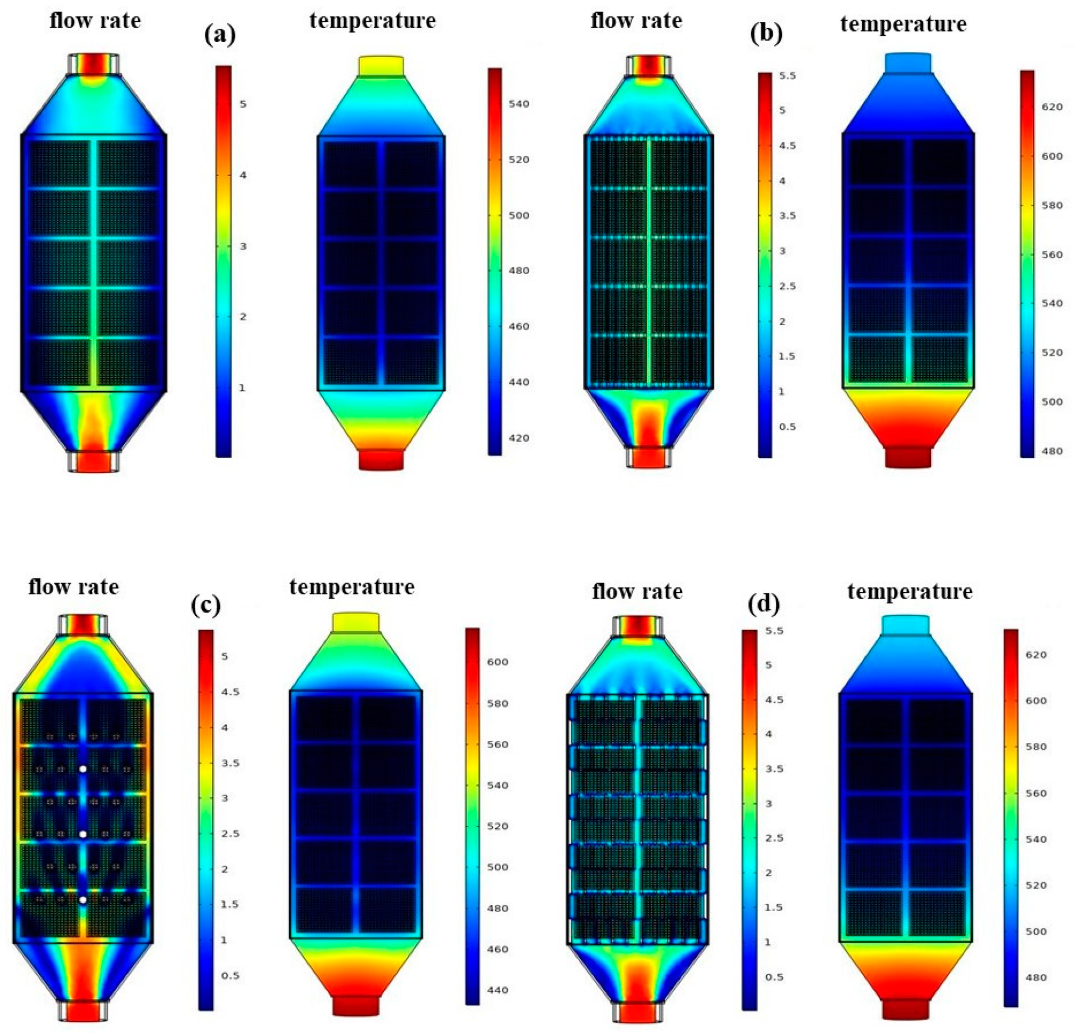
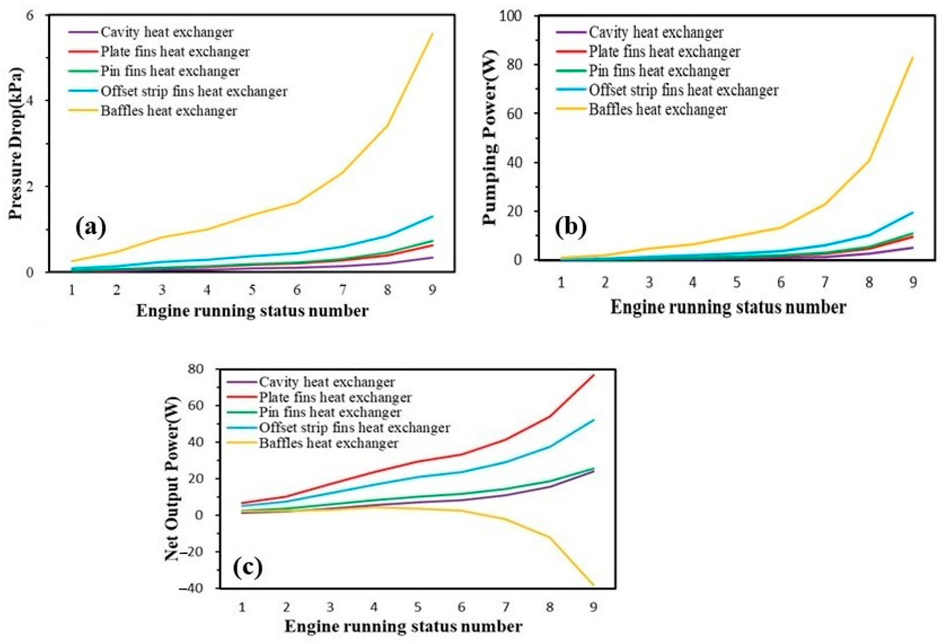
3.1. Design and Simulation of Square Heat Exchangers in Thermoelectric Modules

This study simulates five types of square heat exchangers. The types of heat exchangers include the cavity heat exchanger, plate fin heat exchanger, pin fin heat exchanger, offset strip fin heat exchanger, and baffle plate heat exchanger.
  • Plate Fin Heat Exchanger: Our choice for the plate fin heat exchanger design was influenced by its typical application in electronic components cooling, where flat fins increase heat transfer area. We based our model on Luo et al. [112], with fin thickness (w) of 1.5 mm and fin spacing (d) of 4 mm. Plate fin heat exchangers, while efficient, are more complex to manufacture than simpler designs like cavity heat exchangers. Due to intricate fin structures, this complexity requires precise fabrication techniques and can lead to longer production times, the need for specialized skills, and a higher risk of manufacturing errors. Addressing these challenges is essential for their effective use in thermoelectric generators, particularly given their benefits in waste heat recovery.
  • Pin Fin Heat Exchanger: The pin fin heat exchanger, similar in design to the plate fin, employs cylindrical fins to enhance heat transfer. We derived our model from Wang et al., setting the lateral fin spacing (ST) at 15 mm and longitudinal spacing (SL) at 30 mm [113].
  • Offset Strip Fin Heat Exchanger: Our design for the offset strip fin heat exchanger, a widely used configuration, was chosen for its staggered fin arrangement that significantly increases the heat transfer area. Referencing S. Vale et al. [114], our model features a fin spacing (S) of 8 mm, fin thickness (t) of 1.5 mm, and fin height (h) of 19.5 mm.
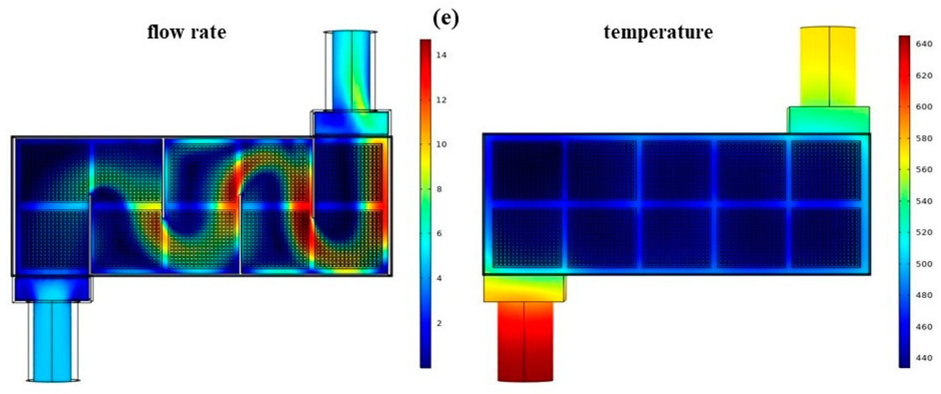
  • Baffle Heat Exchanger: The baffle heat exchanger design was adopted to lengthen the fluid path, enhancing heat transfer compared with previous models. We modeled this based on Rafael et al. [115].
The central rectangular area of the heat exchanger for heat exchange is 227 mm × 95 mm × 24 mm, and it has an inner diameter of 30 mm for both the inlet and outflow. The shell material is made of steel. The plate fin heat exchanger features fins that are 1.5 mm thick and spaced 4 mm apart. The pin fin heat exchanger features a fin arrangement with a transverse spacing of 15 mm and a longitudinal spacing of 30 mm. The fin pitch, which refers to the distance between adjacent fins, is 8 mm. The offset strip fin heat exchanger features a fin thickness measuring 1.5 mm and a fin height of 19.5 mm.
The fixed cooling system’s square tube dimensions are 227 mm × 95 mm × 10 mm. The tube is steel, and the cooling fluid used is water. The thermoelectric module utilizes a configuration in which the chip is positioned on one side alone. The upper section comprises 10 thermoelectric chips arranged in series for thermoelectric conversion. Each chip is composed of 134 rectangular thermocouples. The dimensions of each thermoelectric element are 1.6 mm (length) × 1.6 mm (width) × 3 mm (height), forming a rectangular shape. Figure 2 was created using Solidworks 2018 and data were examined in COMSOL 5.5 [116] software utilizing the finite element approach.

3.2. Simulation of ATEG Power Generation under Real Engine Exhaust Conditions

In order to replicate the power generation of the ATEG under actual exhaust conditions, this work used the gasoline engine employed in the experiments conducted by T.Y. Kim et al. [118]. Simulation parameters were determined by selecting nine operational modes of the engine and using their related exhaust gas flow rates and temperatures. The precise simulation circumstances are outlined in Table 1. The exhaust gas passes via the heat exchanger, where its thermophysical characteristics are simulated using air. The cooling system was designed with a mass flow rate of 0.06 kg/s and a temperature of 353 K [118], while the surrounding temperature is fixed at 298 K.

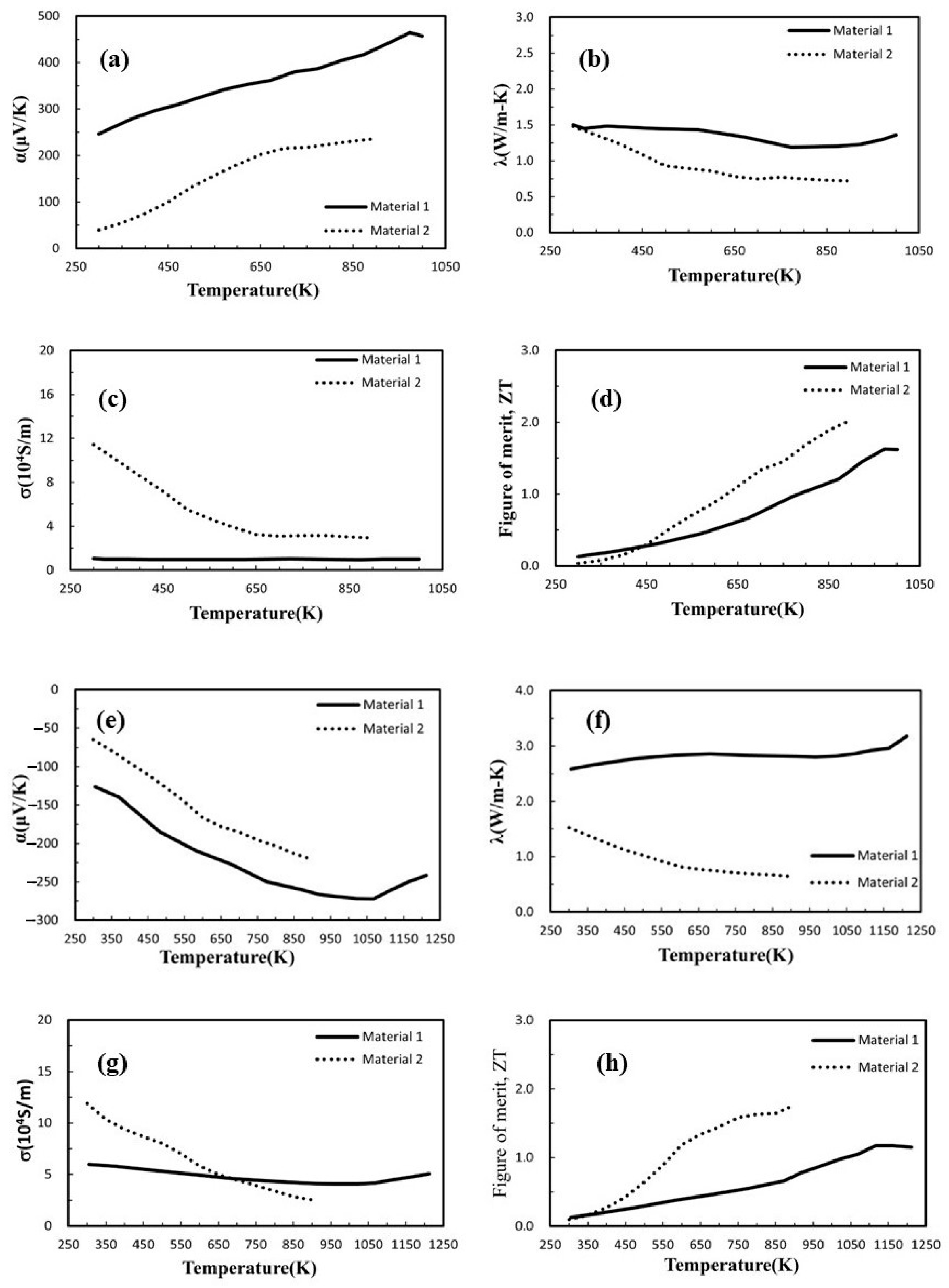
3.3. Thermoelectric Materials

Considering the temperature differential between the cooling system and engine exhaust, materials with superior thermoelectric properties within the 300–1000 K temperature range were selected. The study investigated the influence of diverse thermoelectric material features on power generation efficiency by selecting two sets of distinct thermoelectric materials. The initial group consists of a P-type thermoelectric material called Si62Ge31Au4B3 [119], with a figure of merit (zT) value of 1.63. The second group comprises an N-type thermoelectric material composed of Si0.88Ge0.12 mixed with 5% FeSi2 and 2.5% Ag [120]. This material was sintered at 1000 °C and achieved a zT value 1.20. The second group includes two types of thermoelectric materials. The first type is a P-type material called Pb0.935Na0.025Cd0.04Se0.5S0.25Te0.25 [121], with a peak zT value of 2.00. The second type is an N-type material called Pb0.89Sb0.012Sn0.1Se0.5Te0.25S0.25 [122], which has a zT value of 1.80. Figure 3 depicts the properties of the first set of thermoelectric materials as solid lines for Material 1 and the properties of the second set of thermoelectric materials as dotted lines for Material 2.

4. Model Validation

We thoroughly compared our simulation results, obtained through COMSOL, with existing experimental data [123] to validate the accuracy and reliability of the simulations of heat exchangers. The validation was executed from two distinct perspectives. Firstly, we analyzed the temperature distribution at both ends of the thermoelectric power generation devices in response to hot fluids at various temperatures, with hot fluid temperatures set at 323 K, 333 K, 343 K, 353 K, and 363 K, and cold fluid at 285 K. Both fluids were simulated with a flow rate of 1.3 m/s (as depicted in Figure 4a). Subsequently, we examined the temperature distribution at both ends of the thermoelectric devices corresponding to different flow rates of the cold fluid, with the hot fluid maintained at a flow rate of 0.74 m/s and a temperature of 353 K and the cold fluid’s flow rate varying from 0.01 m/s to 3.1 m/s at 292 K, to assess the impact of the cold fluid flow rate on the temperature distribution of the thermoelectric chip (illustrated in Figure 4b). In the simulations, TH and TC denote the hot-end and cold-end temperatures of the thermoelectric chip, respectively, while TH,ref and TC,ref represent these temperatures in the referenced experimental literature.

5. Results

In this study, the designs of various heat exchangers were based on the spatial constraints of a car’s chassis, with the exhaust gas parameters and heat exchanger dimensions referenced from Table 1 tailored explicitly for automotive applications. The mass flow rate and temperature of the heat source fluid are critical factors influencing the performance of TEG modules. Data from Table 1 indicate that, under operational state 1, the exhaust gas from the engine exhibits the lowest mass flow rate and temperature. In contrast, during operational state 9, these parameters reach their highest values, impacting the efficiency and effectiveness of the TEG system.
When engine exhaust gas enters the heat exchanger, it increases the temperature of the heat exchanger’s shell. The TEG chip and the heat exchanger shell are in direct contact, with the former acting as the hot side and the latter as the cold side for the TEG chip and the cooling system interface. The temperature difference causes the TEG chip to produce a voltage, which generates output power when connected to an external load resistance. This study is structured into three sections:
First, it examines the impact of various heat exchanger designs on the temperature distribution of the engine exhaust gas transmitted to the heat exchanger shell. It also explores the relationship between this temperature distribution and the electrical output of the TEG chip.
Second, it examines the influence of diverse engine operating conditions, distinguished by varying exhaust gas flow rates and temperatures, on the power output of different TEG modules.
Finally, by utilizing the TEG module at peak efficiency, the study investigates the impact of the thermoelectric material’s zT value on the output power.

5.1. Analysis of the Influence of Heat Exchanger Design on Power Generation

In order to examine the temperature distribution and heat transfer properties of thermoelectric generators (TEGs) in heat exchangers with various designs, we implemented conditions corresponding to engine operation state number 1 from Table 1. These conditions were applied to five different types of heat exchangers: the cavity heat exchanger, the plate fin heat exchanger, the pin fin heat exchanger, the offset strip fin heat exchanger, and the baffle plate heat exchanger.
Figure 5a–e depict the exhaust gas flow velocity and temperature distribution for various heat exchangers under engine operation state number 1, as detailed in Table 1. The color distribution in these figures indicates that the plate fin heat exchanger exhibits the most uniform distribution of exhaust gas flow velocity and temperature. This is closely followed by the offset strip fin heat exchanger, which also shows a relatively even distribution, albeit to a lesser extent.
Figure 6a shows how heat exchangers’ internal fin design significantly impacts the supply of thermal energy for thermoelectric conversion in TEGs. The plate pin heat exchanger outperforms the other three heat exchanger types with differing fin designs in heat transmission, resulting in the highest temperature difference in the TEG of up to 148.88 K. Incorporating plate fin heat exchangers in thermoelectric generators involves higher manufacturing costs, attributed to their complex design and material requirements. However, these costs should be weighed against the long-term efficiency gains and potential fuel savings in automotive applications. This cost–benefit analysis is vital for assessing the economic feasibility of plate fin heat exchangers, balancing initial investment against future savings. The offset strip fin heat exchanger reaches a maximum temperature differential of 135.88 K for the TEG. Both share the characteristic of displaying fin patterns. Compared with the other variants, the TEG in the cavity heat exchanger achieves the lowest maximum temperature differential of 72.72 K.
In thermoelectric materials, the voltage produced by the Seebeck effect is dictated by the product of the Seebeck coefficient, the number of thermocouple pairs, and the temperature differential. We modelled the voltage produced by TEGs by using temperature variations between the hot and cold ends of various heat exchangers. This was accomplished by considering the thermoelectric materials’ Seebeck coefficient–temperature relationship, as shown in Figure 3. Several circumstances of temperature difference were simulated across several heat exchanger designs. Figure 6a shows a positive relationship between TEG voltage and temperature differential between hot and cold ends.
The open-circuit voltage produced by each TEG chip is combined, and the current and output power are determined with the external load resistance. In this work, power generation efficiency was investigated to determine the impact of external load resistance. The TEG chips had a total internal resistance ranging from 177–182 Ω across all temperature differential conditions. The narrow range is due to the minor change in the electrical conductivity of the selected thermoelectric materials with temperature. Hence, the external load resistance was adjusted within the range of 1–1000 Ω, approximately five times greater than the internal resistance of the TEG chips, to investigate its impact on the output power.
When the engine is in state 1, the outputting voltage and power of all the chips connected in series are set by the thermoelectric materials, the resistance of the external load, and the sum of the open-circuit voltages of all the TEG chips. Figure 7a shows the voltage and current produced by the circuit when connected to five different types of TEG modules coupled to external load resistances ranging from 1 to 1000 Ω. The current decreases as the external resistance increases, raising the output voltage and generating a diagonal distribution on the graph. As indicated in Figure 6b, the plate fin heat exchanger has the highest output voltage, and the cavity heat exchanger has the lowest.
Figure 7b shows the output power of the five TEG module types for various external load resistances. The maximum values, ranging from 177.00 to 178.85 Ω, match the total internal resistance of the TEG chips, confirming that maximum output power is achieved when the external load resistance equals the TEG chips’ internal resistance.

5.2. Analysis of the Influence of Engine Operating Conditions on Power Generation

This section analyzes the power output generated by TEG modules under nine distinct engine operating conditions while comparing identical operating states across multiple heat exchangers. The nine engine operating stages outlined in Table 1 are utilized to ascertain the TEG modules’ combined power output and overall efficiency.
The temperature differential between the entrance and outlet ends of the cavity TEG module, through which engine exhaust gas travels, is shown in Figure 8a. Because there are no interior fins in this heat exchanger construction, the exhaust gas flows quickly through, resulting in negligible heat transfer. The plate fin heat exchanger, on the other hand, lowers the velocity of exhaust gas flow between the fins due to boundary layer phenomena. Furthermore, the plate fins promote extra heat transmission, resulting in the most significant temperature difference between the inlet and exit. Although the exhaust gas temperature grows with engine load, the temperature differential between the heat exchanger inlet and outlet decreases. This results in a more uniform temperature at the TEG hot end, allowing greater power output.
Figure 8b shows how differences in engine load and heat exchanger design significantly impact the output power of each TEG module. As engine load increases, exhaust gas temperature rises, resulting in a more significant temperature difference between the hot and cold ends of the TEG chips and, as a result, increased power output. At maximum load, the plate fin heat exchanger produces the most power (86.30 W), whereas the cavity heat exchanger produces the least power (29.30 W).
Figure 8b illustrates the temperature difference between the engine exhaust gas at the heat exchanger inlet and outlet, observed under various engine operating conditions. The heat available for the thermoelectric generator (TEG) under different engine loads can be determined using this temperature difference, as shown in Figure 8c. Incorporating plate fins in the exhaust gas heat exchanger significantly improves heat transfer to the TEG. In all heat exchanger models with plate fins, more heat is transmitted to the TEG than the cavity model. Among these, the plate fin heat exchanger delivers the highest heat to the TEG, reaching a maximum of 511 W at full engine load. In contrast, the cavity TEG transfers only 330 W of heat.
The TEG module’s total efficiency η is the ratio of the TEG’s output power to the heat it receives from the engine’s exhaust gas. Figure 8d shows that as the engine loads up, the total efficiency of the TEG module goes up. The plate fin heat exchanger utilizes plate fins to enhance flow dispersion and heat transfer, improving performance. This enhanced design allows the TEG chips to produce electricity using a more significant temperature differential, yielding the highest total efficiency.
The heat recovery efficiency (ηHR) [117] quantifies the total exhaust gas heat utilized by the TEG module. It is determined by the ratio of the TEG’s maximum possible heat input to its actual heat output and can be mathematically represented as:
Q e x h , m a x = m ˙ e x h C p , e x h Δ T e x h , m a x
η H R = Q e x h Q e x h , m a x
The plate fin heat exchanger was studied to examine the influence of engine operating conditions on heat recovery efficiency due to its superior output power and total efficiency. The heat recovery efficiency is calculated using the temperature difference between the inlet and outlet of the heat exchanger, as well as the inlet temperature parameters of the engine exhaust gas, from Table 1.
Figure 9 shows that as the engine load increases, the exhaust gas flow rate and heat content rise due to higher temperatures. As a result, the maximum possible heat input to the TEG module increases significantly with load, from 0.68 to 3.87 kW. However, the heat transferred to the TEG module increases minimally, ranging from 0.24 to 0.51 kW. Comparing these thermal values shows that heat recovery efficiency progressively decreases as engine load rises. While exhaust gas contains much heat, the flow quickly removes it rather than using it for the TEG. The red dots in Figure 9 show that heat recovery efficiency declines with higher loads, falling from 35.90% to 13.19%.
When building thermoelectric generator (TEG) modules for engine waste heat recovery, it is crucial to consider the pressure drop as a significant parameter. A large pressure drop signifies that the engine exhaust gas cannot exit the heat exchanger effectively, leading to back pressure that negatively affects the efficiency and lifespan of the engine. In automotive waste heat recovery systems, TEG modules typically have an acceptable pressure drop of 3 kPa or less [117]. Pressure losses arise when engine exhaust gas enters the heat exchanger, resulting from fluid expansion and contraction and friction between the fluid and the heat exchanger shell. Moreover, including fin designs in the heat exchanger unavoidably results in supplementary losses as the fluid passes over the fins. This issue was investigated by performing simulation analysis on several thermoelectric generator (TEG) modules while considering various engine operating circumstances. The analysis examines the pressure drop that occurs when engine exhaust gas passes through the heat exchanger. Figure 10a shows that the cavity heat exchanger, without internal fin designs, experiences the lowest pressure drop. The pressure loss reaches 0.34 kPa when the engine operates at full load. The pressure decreases in the plate fin, pin fin, and offset strip fin heat exchangers are greater than those in the cavity model, measuring 0.63 kPa, 0.74 kPa, and 1.31 kPa, respectively. The main cause of this is the decrease in pressure at the entrance and exit, as well as the resistance encountered along the walls and fins of the chamber. The pressure loss is considerably more significant for the baffle plate heat exchanger than the other heat exchangers. This is primarily due to boundary layer separation and secondary flow from internal turns. Figure 10a illustrates that the pressure loss in the baffle plate heat exchanger is remarkably high, peaking at 5.56 kPa during maximum engine load. Hence, the baffle plate design is not well suited for TEG modules.
In the exploration of the output power of thermoelectric generator (TEG) modules, it is essential to consider the pump loss power W p u m p generated by the pressure drop of the engine exhaust gas. This consideration enables an assessment of the net output power that the entire TEG module system can achieve. The relationship can be expressed by the following formula:
W p u m p = V ˙ Δ p
W n e t = W W e x h
Similar to Figure 10a, Figure 10b shows that as engine load increases, the pressure drop caused by the exhaust gas rises, resulting in greater loss of engine pump power. The overall pattern closely matches that of the pressure drop. Without internal fins, the cavity heat exchanger has the lowest pressure drop and pump power loss, reaching 5.05 W at peak load. In contrast, the baffle plate heat exchanger exhibits the highest pump power, peaking at 82.88 W.
Figure 10c illustrates that rising engine loads increase heat exchanger pressure drop from the exhaust gas, proportionally elevating pump power loss. The cavity, plate fin, pin fin, and offset strip fin heat exchangers have pressure drops below 1.31 kPa and pump losses under 19.47 W. As a result, their TEG net output power rises with load, albeit less steeply than in Figure 8b. However, the baffle plate heat exchanger experiences significant pressure drops from its structure bends, requiring substantial pumping to propel exhaust gas. Since TEG power generation is low, net output power stays above zero for the first six engine states but becomes negative at higher loads when pump power exceeds TEG output. At maximum load, the net output is −38.31 W, indicating TEG power from the temperature differential cannot compensate for pump losses. The baffle plate heat exchanger TEG module is ineffective for waste heat recovery and unsuitable for application.
It is evident from this analysis that the plate fin heat exchanger outperforms other types of heat exchangers. The primary reasons for its superiority are its design, which not only incorporates a heat interception mechanism for enhanced thermal energy capture but also minimizes back pressure. Additionally, its relatively simple construction results in lower costs for both manufacturing and maintenance.
Our research shows that the plate fin heat exchanger significantly enhances waste gas heat exchange efficiency, leading to improved TEG system performance, with a maximum output power of 86.30 W at the highest engine load. The efficiency of this design ranges between 2.87–16.89%, showing substantial improvements over existing systems.
It is crucial to note that our study’s simulation conditions, particularly regarding engine exhaust gas, differ from those in the existing literature. This difference means a direct comparison may not be fully representative. However, when adjusting our simulation conditions to match typical conditions used in the literature, our results indicate that the overall efficiency of our proposed TEG systems falls within 0.79–2.09%, closely aligning with efficiencies documented in existing research [118]. This comparative analysis, though for reference, suggests that our models are consistent with real-world applications and provides a basis for further scalability and refinement for practical use.
We believe that our study contributes valuable knowledge to the field of thermoelectric technology and supports the broader objective of developing sustainable and efficient transportation solutions.

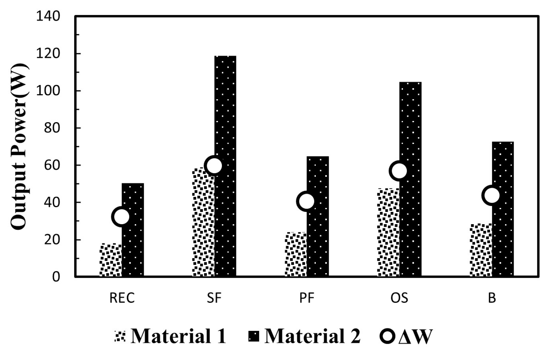
5.3. Evaluation of the Influence of Thermoelectric Materials on Power Generation Efficiency

Thermoelectric material selection significantly impacts TEG module power generation efficiency. Considering engine operating conditions, this section investigates how enhanced thermoelectric material performance affects efficiency. The dimensionless thermoelectric figure of merit, Z T S 2 σ κ T , has three areas for improvement: increasing the Seebeck coefficient, improving electrical conductivity, and minimizing thermal conductivity. Jointly optimizing these enhances efficiency. As Figure 3 shows, superior materials have a lower Seebeck coefficient but reduced thermal conductivity and higher electrical conductivity. Consequently, the ZT value rises from 1.63 to 2.0 for P-type and 1.2 to 1.8 for N-type materials, increasing output power. According to Table 1, automakers regard engine state eight as the most frequent operating condition [20]. We applied this state to examine material influences on different TEG modules. Simulation of TEG chips involved integrating both material sets to determine temperature distribution and voltage. Output power for each TEG module was calculated via thermoelectric theory. Figure 11 shows that improved materials yield higher output power in all TEG modules. Heat exchanger internal fin configuration, impacting shell temperature distribution, also plays a role. The output power difference between TEG modules with the two material sets, depicted by ΔW in Figure 11, shows the most significant increase with the plate fin design and the least with the cavity. This occurs because the materials have higher efficiency at elevated temperatures. The total output power increase is more significant with lower TEG chip thermal conductivity and higher hot-end temperatures.

6. Discussion

This study has provided significant insights into optimizing automotive thermoelectric generators (ATEGs), focusing on heat exchanger efficiency and thermoelectric material properties. Our analysis of various heat exchanger designs aligns with and extends the findings of previous works [112,113,114,115]. Specifically, we demonstrate that specific designs, notably, the plate fin and offset strip fin, significantly improve waste gas heat exchange efficiency. This advancement directly contributes to the enhanced performance of TEG systems in automotive applications. The plate fin heat exchanger shows a remarkable ability to maintain uniform temperature distribution, a critical factor for maximizing TEG efficiency.
The role of thermoelectric material properties in optimizing energy conversion efficiency is also evident. Comparing various thermoelectric materials shows the importance of choosing the right ones by looking at their Seebeck coefficient, electrical and thermal conductivity, and overall figure of merit (zT). Materials with higher zT values, such as Pb0.935Na0.025Cd0.04Se0.5S0.25Te0.25, show a significant increase in power output, underscoring the potential for material advancements in enhancing TEG performance.
However, challenges remain, particularly in the scalability and cost-effectiveness of these technologies. This study’s reliance on simulation data also suggests the need for extensive physical validations under diverse operational conditions to verify the applicability of these findings in real-world scenarios. Future research should, therefore, focus on addressing these challenges, exploring alternative heat exchanger designs, and conducting comprehensive physical validations. Investigations into these systems’ environmental and economic impacts will also be crucial in understanding the full scope of their applicability in sustainable automotive technologies.
In conclusion, this study contributes valuable insights into the field of thermoelectric generators, particularly in automotive applications. The advancements in heat exchanger designs and thermoelectric materials explored here lay a foundation for future research and development, steering us towards more energy-efficient and environmentally friendly automotive technologies.

7. Conclusions

This research marks a notable advancement in the field of automotive thermoelectric generators (ATEGs), concentrating on optimizing heat exchanger designs and exploring thermoelectric materials. Our findings reveal that specific heat exchanger configurations significantly enhance the efficiency of waste gas heat exchange efficiency, directly boosting TEG systems’ performance in automotive applications. Additionally, this research underscores the vital role of thermoelectric material properties in optimizing energy conversion efficiency. The insights obtained from this study contribute to the advancement of thermoelectric technology and support the broader objective of developing sustainable and efficient transportation solutions.
Future directions for automotive thermoelectric recovery systems include investigating alternative heat exchanger designs (including design optimization, baffle geometry alterations, and incorporating flow directors), adaptation to different engine systems, exploring alternative waste heat recovery technologies, conducting physical validations, and testing various thermoelectric materials. These steps will ensure optimal performance across diverse driving conditions and vehicle models. The promising results of this study encourage further exploration in this field, suggesting substantial environmental and economic benefits for the automotive industry. This research lays the foundation for future advancements, steering us towards realizing more eco-friendly and energy-efficient vehicles aligned with global sustainability efforts.
While this study contributes significantly to the field of automotive thermoelectric generators (ATEGs), it acknowledges certain limitations. The scope of our research was confined to simulation-based analysis, which necessitates validation through experimental and real-world testing to ensure practical applicability. Additionally, the cost implications of the proposed designs and materials were not exhaustively explored, which is critical for commercial viability. Despite these limitations, our research profoundly impacts the understanding of heat exchanger designs and thermoelectric materials in ATEGs. The findings offer a foundation for future research into sustainable transportation technologies, with potential implications for reducing vehicle emissions and improving energy efficiency. Future work should bridge the gap between simulation and practical application, explore cost-effective solutions, and extend the study to diverse automotive models and environmental conditions.
In addressing the identified limitations of baffle plate heat exchangers, particularly under high engine loads, future research will focus on a multi-faceted approach to optimize their efficiency. Key areas of development include design optimization for reduced flow resistance, exploration of alternative materials for enhanced thermal conductivity and lighter weight, and geometrical modifications to the baffle plates to improve exhaust gas flow dynamics. Additionally, the introduction of flow directors will be investigated to manage exhaust gas flow more efficiently, thereby reducing pressure drops while maintaining effective heat transfer. These strategies will be validated through advanced computational fluid dynamics (CFD) simulations and rigorous experimental testing. This holistic approach aims to mitigate the challenges of negative net output power and advance the overall performance and applicability of thermoelectric generators in automotive and other high-demand applications.

Author Contributions

Conceptualization, C.-I.W. and C.-Y.C.; methodology, C.-I.W. and C.-Y.C.; software, C.-Y.C.; validation, C.-Y.C.; formal analysis, C.-I.W. and C.-Y.C.; investigation, C.-I.W. and C.-Y.C.; resources, C.-I.W.; data curation, C.-Y.C.; writing—original draft preparation, C.-I.W., K.-W.D., Y.-C.C. and C.-Y.C.; writing—review and editing, C.-I.W.; visualization, C.-Y.C.; supervision, C.-I.W.; project administration, C.-I.W.; funding acquisition, C.-I.W. All authors have read and agreed to the published version of the manuscript.

Funding

This research was funded by National Science and Technology Council of Taiwan, grant number 109-2221-E-019-013 and 111-2221-E-019-060.

Data Availability Statement

The original contributions presented in the study are included in the article, further inquiries can be directed to the corresponding author.

Conflicts of Interest

The authors declare no conflicts of interest.

References

  1. Panday, A.; Bansal, H.O. Green transportation: Need, technology and challenges. Int. J. Glob. Energy Issues 2014, 37, 304–318. [Google Scholar] [CrossRef]
  2. Al-Thani, H.; Koç, M.; Isaifan, R.J.; Bicer, Y. A Review of the Integrated Renewable Energy Systems for Sustainable Urban Mobility. Sustainability 2022, 14, 10517. [Google Scholar] [CrossRef]
  3. Helms, H.; Pehnt, M.; Lambrecht, U.; Liebich, A. Electric vehicle and plug-in hybrid energy efficiency and life cycle emissions. In Proceedings of the 18th International Symposium Transport and Air Pollution, Kos, Greece, 21–23 June 2010. [Google Scholar]
  4. Carpenter, J.A.; Gibbs, J.; Pesaran, A.A.; Marlino, L.D.; Kelly, K. Road transportation vehicles. MRS Bull. 2008, 33, 439–444. [Google Scholar] [CrossRef]
  5. Hermans, J. The challenge of energy-efficient transportation. MRS Energy Sustain. 2017, 4, E1. [Google Scholar] [CrossRef]
  6. Tsolakis, A.; Bogarra, M.; Herreros, J. Road Vehicle Technologies and Fuels. In Environmental Impacts of Road Vehicles: Past, Present and Future; Royal Society of Chemistry: London, UK, 2017. [Google Scholar]
  7. Hu, X.; Chang, S.; Li, J.; Qin, Y. Energy for sustainable road transportation in China: Challenges, initiatives and policy implications. Energy 2010, 35, 4289–4301. [Google Scholar] [CrossRef]
  8. Szymanski, P.; Ciuffo, B.; Fontaras, G.; Martini, G.; Pekar, F. The future of road transport in Europe. Environmental implications of automated, connected and low-carbon mobility. Combust. Engines 2021, 186, 3–10. [Google Scholar] [CrossRef]
  9. Lin, W.; Sunden, B. Vehicle Cooling Systems for Reducing Fuel Consumption and Carbon Dioxide: Literature Survey; SAE Technical Paper; SAE International: Warrendale, PA, USA, 2010. [Google Scholar]
  10. Johnson, V.H. Heat-Generated Cooling Opportunities in Vehicles; SAE Technical Paper; SAE International: Warrendale, PA, USA, 2002. [Google Scholar]
  11. Stuban, N.; Torok, A. Utilization of exhaust gas thermal energy–theoretical investigation. In Proceedings of the 33rd International Spring Seminar on Electronics Technology, ISSE 2010, Warsaw, Poland, 12–16 May 2010; pp. 268–272. [Google Scholar]
  12. Mittal, A.; Shukla, D.; Chauhan, K.P. Technology a refrigeration system for an automobile based on vapor absorption refrigeration cycle using waste heat energy from the engine. Int. J. Eng. Sci. Res. Technol. 2015, 4, 249–267. [Google Scholar]
  13. op de Veigh, J.; Glynatsis, N.; Gurung, P.; Wang, C. A comparative analysis of waste heat recovery systems in vehicles and their viability in real-world applications. PAM Rev. Energy Sci. Technol. 2019, 6, 88–109. [Google Scholar] [CrossRef]
  14. Hilali, I. An application of engine exhaust gas driven cooling system in automobile air-conditioning system. J. Therm. Sci. Technol. Isı Bilim. Ve Tek. Derg. 2015, 35, 27. [Google Scholar]
  15. Talbi, M.; Agnew, B. Energy recovery from diesel engine exhaust gases for performance enhancement and air conditioning. Appl. Therm. Eng. 2002, 22, 693–702. [Google Scholar] [CrossRef]
  16. Lubikowski, K.; Radkowski, S.; Szczurowski, K.; Wikary, M. Energy scavenging in a vehicle’s exhaust system. J. Kones Powertrain Transp. 2015, 19, 253–261. [Google Scholar] [CrossRef]
  17. Maske, P.; Chel, A.; Goyal, P.K.; Kaushik, G. Sustainable perspective of electric vehicles and its future prospects. J. Sustain. Mater. Process. Manag. 2021, 1, 17–32. [Google Scholar] [CrossRef]
  18. Todorovic, M.; Simic, M. Current state of the transition to electrical vehicles. In Proceedings of the Intelligent Interactive Multimedia Systems and Services: Proceedings of 2018 Conference 11, Gold Coast, Australia, 20–22 June 2018; pp. 130–139. [Google Scholar]
  19. Mehar, S.; Zeadally, S.; Remy, G.; Senouci, S.M. Sustainable transportation management system for a fleet of electric vehicles. IEEE Trans. Intell. Transp. Syst. 2014, 16, 1401–1414. [Google Scholar] [CrossRef]
  20. Sun, X.; Li, Z.; Wang, X.; Li, C. Technology development of electric vehicles: A review. Energies 2019, 13, 90. [Google Scholar] [CrossRef]
  21. Folkson, R. Alternative Fuels and Advanced Vehicle Technologies for Improved Environmental Performance; Woodhead Publishing: Sawston, UK, 2014. [Google Scholar]
  22. Adnan, N.A. An Overview of Electric Vehicle Technology: A vision towards sustainable transportation. In Intelligent Transportation and Planning: Breakthroughs in Research and Practice; IGI Global: Hershey, PA, USA, 2018. [Google Scholar]
  23. Bekey, I.V. Historical Evolution of Tethers in Space; NASA: Washington, DC, USA, 1986.
  24. Wen, H.; Jin, D.P.; Hu, H.Y. Advances in dynamics and control of tethered satellite systems. Acta Mech. Sin. 2008, 24, 229–241. [Google Scholar] [CrossRef]
  25. Liu, Z.; Tian, B.; Li, Y.; Guo, Z.; Zhang, Z.; Luo, Z.; Zhao, L.; Lin, Q.; Lee, C.; Jiang, Z. Evolution of Thermoelectric Generators: From Application to Hybridization. Small 2023, 19, 2304599. [Google Scholar] [CrossRef] [PubMed]
  26. Crane, D.; LaGrandeur, J.; Jovovic, V.; Ranalli, M.; Adldinger, M.; Poliquin, E.; Dean, J.; Kossakovski, D.; Mazar, B.; Maranville, C. TEG on-vehicle performance and model validation and what it means for further TEG development. J. Electron. Mater. 2013, 42, 1582–1591. [Google Scholar] [CrossRef]
  27. Aswal, D.K.; Basu, R.; Singh, A. Key issues in development of thermoelectric power generators: High figure-of-merit materials and their highly conducting interfaces with metallic interconnects. Energy Convers. Manag. 2016, 114, 50–67. [Google Scholar] [CrossRef]
  28. Sharma, A.; Lee, J.H.; Kim, K.H.; Jung, J.P. Recent Advances in Thermoelectric Power Generation Technology. J. Microelectron. Packag. Soc. 2017, 24, 9–16. [Google Scholar] [CrossRef]
  29. Hatzikraniotis, E.; Zorbas, K.; Samaras, I.; Kyratsi, T.; Paraskevopoulos, K. Efficiency study of a commercial thermoelectric power generator (TEG) under thermal cycling. J. Electron. Mater. 2010, 39, 2112–2116. [Google Scholar] [CrossRef]
  30. Rad, M.K.; Rezania, A.; Omid, M.; Rajabipour, A.; Rosendahl, L. Study on material properties effect for maximization of thermoelectric power generation. Renew. Energy 2019, 138, 236–242. [Google Scholar]
  31. Meng, J.-H.; Zhang, X.-X.; Wang, X.-D. Characteristics analysis and parametric study of a thermoelectric generator by considering variable material properties and heat losses. Int. J. Heat Mass Transf. 2015, 80, 227–235. [Google Scholar] [CrossRef]
  32. Zorbas, K.; Hatzikraniotis, E.; Paraskevopoulos, K. Power and Efficiency Calculation in Commercial TEG and Application in Wasted Heat Recovery in Automobile. In Proceedings of the 5th European Conference on Thermoelectrics, Odessa, Ukraine, 10–12 September 2007. [Google Scholar]
  33. Dimaggio, E.; Rossella, F.; Pennelli, G. Management of the output electrical power in thermoelectric generators. Electronics 2019, 8, 1514. [Google Scholar] [CrossRef]
  34. Gayner, C.; Kar, K.K. Recent advances in thermoelectric materials. Prog. Mater. Sci. 2016, 83, 330–382. [Google Scholar] [CrossRef]
  35. Ren, P.; Liu, Y.; He, J.; Lv, T.; Gao, J.; Xu, G. Recent advances in inorganic material thermoelectrics. Inorg. Chem. Front. 2018, 5, 2380–2398. [Google Scholar] [CrossRef]
  36. Li, Q.-Y.; Hao, Q.; Zhu, T.; Zebarjadi, M. Nanostructured and heterostructured 2D materials for thermoelectrics. Eng. Sci. 2020, 13, 24–50. [Google Scholar] [CrossRef]
  37. Jaldurgam, F.F.; Ahmad, Z.; Touati, F. Low-toxic, earth-abundant nanostructured materials for thermoelectric applications. Nanomaterials 2021, 11, 895. [Google Scholar] [CrossRef]
  38. Liu, W.; Jie, Q.; Kim, H.S.; Ren, Z. Current progress and future challenges in thermoelectric power generation: From materials to devices. Acta Mater. 2015, 87, 357–376. [Google Scholar] [CrossRef]
  39. Vaqueiro, P.; Powell, A.V. Recent developments in nanostructured materials for high-performance thermoelectrics. J. Mater. Chem. 2010, 20, 9577–9584. [Google Scholar] [CrossRef]
  40. Xue, Y.; Gao, C.; Liang, L.; Wang, X.; Chen, G. Nanostructure controlled construction of high-performance thermoelectric materials of polymers and their composites. J. Mater. Chem. A 2018, 6, 22381–22390. [Google Scholar] [CrossRef]
  41. Mori, T. Novel principles and nanostructuring methods for enhanced thermoelectrics. Small 2017, 13, 1702013. [Google Scholar] [CrossRef] [PubMed]
  42. Molina, M.G.; Juanicó, L.E.; Rinalde, G.F. Design of innovative power conditioning system for the grid integration of thermoelectric generators. Int. J. Hydrogen Energy 2012, 37, 10057–10063. [Google Scholar] [CrossRef]
  43. Li, B.; Huang, K.; Yan, Y.; Li, Y.S.; Twaha, S.; Zhu, J. Heat transfer enhancement of a modularised thermoelectric power generator for passenger vehicles. Appl. Energy 2017, 205, 868–879. [Google Scholar] [CrossRef]
  44. Huang, K.; Yan, Y.; Li, B.; Li, Y.S.; Li, K.; Li, J. A Novel Design of Thermoelectric Generator for Automotive Waste Heat Recovery. Automot. Innov. 2018, 1, 54–61. [Google Scholar] [CrossRef]
  45. Shu, G.; Ma, X.; Tian, H.; Yang, H.; Chen, T.; Li, X. Configuration optimization of the segmented modules in an exhaust-based thermoelectric generator for engine waste heat recovery. Energy 2018, 160, 612–624. [Google Scholar] [CrossRef]
  46. Wang, T.; Ma, S. TEG heat performance study about improved fin structures. Therm. Sci. 2016, 22, 64. [Google Scholar]
  47. Span, G.; Wagner, M.; Grasser, T.; Holmgren, L. Miniaturized TEG with thermal generation of free carriers. Phys. Status Solidi (RRL)–Rapid Res. Lett. 2007, 1, 241–243. [Google Scholar] [CrossRef]
  48. Peng, W.; Jin, Y.; Liu, D.; Qiming, L. Research, Development, and Applications of the High-Power Thermoelectric Generation Technology. Sustain. Energy 2013, 3, 1–7. [Google Scholar]
  49. Pfeiffelmann, B.; Diederich, M.; Benim, A.C.; Hamberger, A.; Heese, M. Development of a heat exchanger for cogeneration via TEG. In Proceedings of the E3S Web of Conferences, Paris, France, 18–19 May 2021; p. 02002. [Google Scholar]
  50. Zhang, Y.; Cleary, M.; Wang, X.; Kempf, N.; Schoensee, L.; Yang, J.; Joshi, G.; Meda, L. High-temperature and high-power-density nanostructured thermoelectric generator for automotive waste heat recovery. Energy Convers. Manag. 2015, 105, 946–950. [Google Scholar] [CrossRef]
  51. Liu, X.; Deng, Y.; Li, Z.; Su, C. Performance analysis of a waste heat recovery thermoelectric generation system for automotive application. Energy Convers. Manag. 2015, 90, 121–127. [Google Scholar] [CrossRef]
  52. Chen, M.; Lund, H.; Rosendahl, L.A.; Condra, T.J. Energy efficiency analysis and impact evaluation of the application of thermoelectric power cycle to today’s CHP systems. Appl. Energy 2010, 87, 1231–1238. [Google Scholar] [CrossRef]
  53. Yang, J. Potential applications of thermoelectric waste heat recovery in the automotive industry. In Proceedings of the ICT 2005. 24th International Conference on Thermoelectrics, Clemson, SC, USA, 19–23 June 2005; pp. 170–174. [Google Scholar]
  54. Kumar, S.; Heister, S.D.; Xu, X.; Salvador, J.R.; Meisner, G.P. Thermoelectric generators for automotive waste heat recovery systems part I: Numerical modeling and baseline model analysis. J. Electron. Mater. 2013, 42, 665–674. [Google Scholar] [CrossRef]
  55. Espinosa, N.; Lazard, M.; Aixala, L.; Scherrer, H. Modeling a thermoelectric generator applied to diesel automotive heat recovery. J. Electron. Mater. 2010, 39, 1446–1455. [Google Scholar] [CrossRef]
  56. Lan, S.; Yang, Z.; Chen, R.; Stobart, R. A dynamic model for thermoelectric generator applied to vehicle waste heat recovery. Appl. Energy 2018, 210, 327–338. [Google Scholar] [CrossRef]
  57. Nadaf, N.; Preethi, A. Review on waste heat energy harvesting using TEG: Applications and enhancements. In Proceedings of the 2021 8th International Conference on Smart Computing and Communications (ICSCC), Kochi, Kerala, India, 1–3 July 2021; pp. 334–339. [Google Scholar]
  58. Hsu, C.-T.; Huang, G.-Y.; Chu, H.-S.; Yu, B.; Yao, D.-J. Experiments and simulations on low-temperature waste heat harvesting system by thermoelectric power generators. Appl. Energy 2011, 88, 1291–1297. [Google Scholar] [CrossRef]
  59. Horst, T.A.; Rottengruber, H.-S.; Seifert, M.; Ringler, J. Dynamic heat exchanger model for performance prediction and control system design of automotive waste heat recovery systems. Appl. Energy 2013, 105, 293–303. [Google Scholar] [CrossRef]
  60. Suter, C.; Jovanovic, Z.; Steinfeld, A. A 1 kWe thermoelectric stack for geothermal power generation–Modeling and geometrical optimization. Appl. Energy 2012, 99, 379–385. [Google Scholar] [CrossRef]
  61. Royale, A.; Simic, M.; Lappas, P. Engine exhaust manifold with thermoelectric generator unit. Int. J. Engine Res. 2021, 22, 2180–2188. [Google Scholar] [CrossRef]
  62. Albatati, F.; Attar, A. Analytical and experimental study of thermoelectric generator (TEG) system for automotive exhaust waste heat recovery. Energies 2021, 14, 204. [Google Scholar] [CrossRef]
  63. Omar, M.S.; Singh, B.; Remeli, M.F. Motorcycle Waste Heat Energy Harvesting Using Thermoelectric Generators. J. Electron. Mater. 2020, 49, 2838–2845. [Google Scholar] [CrossRef]
  64. Choi, Y.; Negash, A.; Kim, T.Y. Waste heat recovery of diesel engine using porous medium-assisted thermoelectric generator equipped with customized thermoelectric modules. Energy Convers. Manag. 2019, 197, 111902. [Google Scholar] [CrossRef]
  65. Wang, Y.; Li, S.; Yang, X.; Deng, Y.; Su, C. Numerical and experimental investigation for heat transfer enhancement by dimpled surface heat exchanger in thermoelectric generator. J. Electron. Mater. 2016, 45, 1792–1802. [Google Scholar] [CrossRef]
  66. Ezzitouni, S.; Fernández-Yáñez, P.; Sánchez, L.; Armas, O. Global energy balance in a diesel engine with a thermoelectric generator. Appl. Energy 2020, 269, 115139. [Google Scholar] [CrossRef]
  67. Liu, X.; Deng, Y.; Chen, S.; Wang, W.; Xu, Y.; Su, C. A case study on compatibility of automotive exhaust thermoelectric generation system, catalytic converter and muffler. Case Stud. Therm. Eng. 2014, 2, 62–66. [Google Scholar] [CrossRef]
  68. Kumar, R.C.; Sonthalia, A.; Goel, R. Experimental study on waste heat recovery from an IC engine using thermoelectric technology. Therm. Sci. 2011, 15, 1011–1022. [Google Scholar] [CrossRef]
  69. Lin, L.; Zhang, Y.-F.; Liu, H.-B.; Meng, J.-H.; Chen, W.-H.; Wang, X.-D. A new configuration design of thermoelectric cooler driven by thermoelectric generator. Appl. Therm. Eng. 2019, 160, 114087. [Google Scholar] [CrossRef]
  70. Feng, Y.; Chen, L.; Meng, F.; Sun, F. Thermodynamic analysis of TEG-TEC device including influence of Thomson effect. J. Non-Equilib. Thermodyn. 2018, 43, 75–86. [Google Scholar] [CrossRef]
  71. Kwan, T.H.; Wu, X.; Yao, Q. Complete implementation of the combined TEG-TEC temperature control and energy harvesting system. Control Eng. Pract. 2020, 95, 104224. [Google Scholar] [CrossRef]
  72. Liu, C.; Pan, X.; Zheng, X.; Yan, Y.; Li, W. An experimental study of a novel prototype for two-stage thermoelectric generator from vehicle exhaust. J. Energy Inst. 2016, 89, 271–281. [Google Scholar] [CrossRef]
  73. Quan, R.; Liu, G.; Wang, C.; Zhou, W.; Huang, L.; Deng, Y. Performance investigation of an exhaust thermoelectric generator for military SUV application. Coatings 2018, 8, 45. [Google Scholar] [CrossRef]
  74. Du, Q.; Diao, H.; Niu, Z.; Zhang, G.; Shu, G.; Jiao, K. Effect of cooling design on the characteristics and performance of thermoelectric generator used for internal combustion engine. Energy Convers. Manag. 2015, 101, 9–18. [Google Scholar] [CrossRef]
  75. Kishore, R.A.; Mahajan, R.L.; Priya, S. Combinatory finite element and artificial neural network model for predicting performance of thermoelectric generator. Energies 2018, 11, 2216. [Google Scholar] [CrossRef]
  76. Dousti, M.J.; Petraglia, A.; Pedram, M. Accurate electrothermal modeling of Thermoelectric Generators. In Proceedings of the 2015 Design, Automation & Test in Europe Conference & Exhibition (DATE), Grenoble, France, 9–13 March 2015; pp. 1603–1606. [Google Scholar]
  77. Woodall, T.S.; Graham, R.L.; Castain, R.H.; Daniel, D.J.; Sukalski, M.W.; Fagg, G.E.; Gabriel, E.; Bosilca, G.; Angskun, T.; Dongarra, J.J. TEG: A high-performance, scalable, multi-network point-to-point communications methodology. In Proceedings of the Recent Advances in Parallel Virtual Machine and Message Passing Interface: 11th European PVM/MPI Users’ Group Meeting, Budapest, Hungary, 19–22 September 2004; Proceedings 11. pp. 303–310. [Google Scholar]
  78. Hendricks, T.J.; Yee, S.; LeBlanc, S. Cost scaling of a real-world exhaust waste heat recovery thermoelectric generator: A deeper dive. J. Electron. Mater. 2016, 45, 1751–1761. [Google Scholar] [CrossRef]
  79. Benday, N.S.; Dryden, D.M.; Kornbluth, K.; Stroeve, P. A temperature-variant method for performance modeling and economic analysis of thermoelectric generators: Linking material properties to real-world conditions. Appl. Energy 2017, 190, 764–771. [Google Scholar] [CrossRef]
  80. Ochs, F.; Dahash, A.; Tosatto, A.; Reisenbichler, M.; O’Donovan, K.; Gauthier, G.; Skov, C.K.; Schmidt, T. Comprehensive comparison of different models for large-scale thermal energy storage. In Proceedings of the International Renewable Energy Storage Conference 2021 (IRES 2021), Online, 16–18 March 2021; pp. 36–51. [Google Scholar]
  81. Egea López, E. Simulation Scalability Issues in Wireless Sensor Networks; IEEE: Piscataway, NJ, USA, 2006. [Google Scholar]
  82. Zhang, D.; Wang, Y.; Yang, Y. Design, Performance, and Application of Thermoelectric Nanogenerators. Small 2019, 15, e1805241. [Google Scholar] [CrossRef]
  83. Pataki, N.; Rossi, P.; Caironi, M. Solution processed organic thermoelectric generators as energy harvesters for the Internet of Things. Appl. Phys. Lett. 2022, 121, 230501. [Google Scholar] [CrossRef]
  84. Bhuiyan, M.R.A.; Mamur, H.; Dilmaç, Ö.F.; Üstüner, M.A. Opportunities for thermoelectric generators in supporting a low carbon economy. Nanomater. Energy 2022, 11, 8–26. [Google Scholar] [CrossRef]
  85. El-Shahat, A.; Bhuiyan, M.S.R. Thermoelectric Generator Performances and Efficiency Analysis Integrated with MPPT Techniques. In Proceedings of the 2021 International Conference on Sustainable Energy and Future Electric Transportation (SEFET), Hyderabad, India, 21–23 January 2021; pp. 1–7. [Google Scholar]
  86. Jin, A.J.; Peng, W.; Liu, D.; Xu, S.; Chang, Y.; Zhang, H. Brief Review of Solid State Thermal Electric Energy and Applications in Solar Electricity. Sustain. Energy 2012, 2, 35–41. [Google Scholar] [CrossRef]
  87. Wang, H.; Jasim, A.; Chen, X. Energy harvesting technologies in roadway and bridge for different applications—A comprehensive review. Appl. Energy 2018, 212, 1083–1094. [Google Scholar] [CrossRef]
  88. Farmer, J.R. A Comparison of Power Harvesting Techniques and Related Energy Storage Issues. Ph.D. Thesis, Virginia Tech, Blacksburg, VA, USA, 2007. [Google Scholar]
  89. Jouhara, H.; Żabnieńska-Góra, A.; Khordehgah, N.; Doraghi, Q.; Ahmad, L.; Norman, L.; Axcell, B.; Wrobel, L.; Dai, S. Thermoelectric generator (TEG) technologies and applications. Int. J. Thermofluids 2021, 9, 100063. [Google Scholar] [CrossRef]
  90. Saharun, I.; Saudin, N.; Mohamed, M.; Jamel, N.; Mohamed, H. Comparative Study of Thermal Energy Harvesting on Agricultural Soils using Thermoelectric Generator (TEG). Proc. J. Phys. Conf. Ser. 2021, 1878, 012043. [Google Scholar] [CrossRef]
  91. Mamur, H.; Ahiska, R. A Review: Thermoelectric Generators in Renewable Energy. Int. J. Renew. Energy Res. 2014, 4, 128–136. [Google Scholar]
  92. Ashworth, A.; Lindsay, K.; Popp, M.; Owens, P. Economic and environmental impact assessment of tractor guidance technology. Agric. Environ. Lett. 2018, 3, 180038. [Google Scholar] [CrossRef]
  93. Patyk, A. Thermoelectric generators for efficiency improvement of power generation by motor generators–environmental and economic perspectives. Appl. Energy 2013, 102, 1448–1457. [Google Scholar] [CrossRef]
  94. Dincer, I.; Rosen, M.A. Energetic, environmental and economic aspects of thermal energy storage systems for cooling capacity. Appl. Therm. Eng. 2001, 21, 1105–1117. [Google Scholar] [CrossRef]
  95. Patyk, A. Thermoelectrics: Impacts on the environment and sustainability. J. Electron. Mater. 2010, 39, 2023–2028. [Google Scholar] [CrossRef]
  96. Kawajiri, K.; Kishita, Y.; Shinohara, Y. Life Cycle Assessment of Thermoelectric Generators (TEGs) in an Automobile Application. Sustainability 2021, 13, 13630. [Google Scholar] [CrossRef]
  97. Konyuhov, V.Y.; Gladkih, A.; Galyautdinov, I.; Severina, Y.D. Economic aspects of green technologies. Proc. IOP Conf. Ser. Earth Environ. Sci. 2019, 350, 012036. [Google Scholar] [CrossRef]
  98. Menikpura, S.; Sang-Arun, J.; Bengtsson, M. Assessment of environmental and economic performance of Waste-to-Energy facilities in Thai cities. Renew. Energy 2016, 86, 576–584. [Google Scholar] [CrossRef]
  99. Shekarriz, R.; Call, C.J. State-of-the-art in micro-and meso-scale heat exchangers. In Proceedings of the ASME International Mechanical Engineering Congress and Exposition, Nashville, TN, USA, 14–19 November 1999; pp. 53–61. [Google Scholar]
  100. Mcquiston, F.C. Finned Tube Heat Exchangers: State of the Art for the Air Side; U.S. Department of Energy Office of Scientific and Technical Information: Oak Ridge, TN, USA, 1980.
  101. Aydin, D.; Casey, S.P.; Riffat, S. The latest advancements on thermochemical heat storage systems. Renew. Sustain. Energy Rev. 2015, 41, 356–367. [Google Scholar] [CrossRef]
  102. Aridi, R.; Faraj, J.; Ali, S.; Lemenand, T.; Khaled, M. Thermoelectric power generators: State-of-the-art, heat recovery method, and challenges. Electricity 2021, 2, 359–386. [Google Scholar] [CrossRef]
  103. Chen, X.; Su, Y.; Reay, D.; Riffat, S. Recent research developments in polymer heat exchangers—A review. Renew. Sustain. Energy Rev. 2016, 60, 1367–1386. [Google Scholar] [CrossRef]
  104. Soleimani, Z.; Zoras, S.; Ceranic, B.; Shahzad, S.; Cui, Y. A review on recent developments of thermoelectric materials for room-temperature applications. Sustain. Energy Technol. Assess. 2020, 37, 100604. [Google Scholar] [CrossRef]
  105. Ohadi, M.; Zhang, X.; Keramati, H.; Arie, M.; Singer, F.; Tiwari, R.; Shooshtari, A. Recent developments in high temperature heat exchangers: A review. Front. Heat Mass Transf. 2018, 11, 18. [Google Scholar] [CrossRef]
  106. Yan, S.-R.; Moria, H.; Asaadi, S.; Sadighi Dizaji, H.; Khalilarya, S.; Jermsittiparsert, K. Performance and profit analysis of thermoelectric power generators mounted on channels with different cross-sectional shapes. Appl. Therm. Eng. 2020, 176, 115455. [Google Scholar] [CrossRef]
  107. Ma, T.; Lu, X.; Pandit, J.; Ekkad, S.V.; Huxtable, S.T.; Deshpande, S.; Wang, Q.-w. Numerical study on thermoelectric–hydraulic performance of a thermoelectric power generator with a plate-fin heat exchanger with longitudinal vortex generators. Appl. Energy 2017, 185, 1343–1354. [Google Scholar] [CrossRef]
  108. Zhang, Q.-H.; Bai, S.-Q.; Chen, L.-D. Technologies and Applications of Thermoelectric Devices: Current Status, Challenges and Prospects. J. Inorg. Mater. 2019, 34, 279–293. [Google Scholar] [CrossRef]
  109. Chen, W.-H.; Lin, Y.-X.; Wang, X.-D.; Lin, Y.-L. A comprehensive analysis of the performance of thermoelectric generators with constant and variable properties. Appl. Energy 2019, 241, 11–24. [Google Scholar] [CrossRef]
  110. Sandoz-Rosado, E.J. Investigation and Development of Advanced Models of Thermoelectric Generators for Power Generation Applications; Rochester Institute of Technology: Rochester, NY, USA, 2009. [Google Scholar]
  111. Saqr, K.M.; Mansour, M.K.; Musa, M. Thermal design of automobile exhaust based thermoelectric generators: Objectives and challenges. Int. J. Automot. Technol. 2008, 9, 155–160. [Google Scholar] [CrossRef]
  112. Luo, D.; Wang, R.; Yu, W.; Zhou, W. A numerical study on the performance of a converging thermoelectric generator system used for waste heat recovery. Appl. Energy 2020, 270, 115181. [Google Scholar] [CrossRef]
  113. Wang, J.; Song, X.; Li, Y.; Zhang, C.; Zhao, C.; Zhu, L. Modeling and analysis of thermoelectric generators for diesel engine exhaust heat recovery system. J. Energy Eng. 2020, 146, 04020002. [Google Scholar] [CrossRef]
  114. Vale, S.; Heber, L.; Coelho, P.; Silva, C. Parametric study of a thermoelectric generator system for exhaust gas energy recovery in diesel road freight transportation. Energy Convers. Manag. 2017, 133, 167–177. [Google Scholar] [CrossRef]
  115. Ramírez, R.; Gutiérrez, A.S.; Eras, J.J.C.; Valencia, K.; Hernández, B.; Forero, J.D. Evaluation of the energy recovery potential of thermoelectric generators in diesel engines. J. Clean. Prod. 2019, 241, 118412. [Google Scholar] [CrossRef]
  116. COMSOL Multiphysics. Available online: https://www.comsol.com/ (accessed on 20 November 2023).
  117. Chen, C.-Y. Analysis of thermoelectric generators applied to waste heat recovery. In Master of Science; Mechanical and Mechatronic Engineering, National Taiwan Ocean University: Keelung, Taiwan, 2021. [Google Scholar]
  118. Kim, T.Y.; Kwak, J.; Kim, B.-W. Application of compact thermoelectric generator to hybrid electric vehicle engine operating under real vehicle operating conditions. Energy Convers. Manag. 2019, 201, 112150. [Google Scholar] [CrossRef]
  119. Muthusamy, O.; Ghodke, S.; Singh, S.; Delime-Codrin, K.; Nishino, S.; Adachi, M.; Yamamoto, Y.; Matsunami, M.; Harish, S.; Shimomura, M. Enhancement of the thermoelectric performance of Si-Ge nanocomposites containing a small amount of Au and optimization of boron doping. J. Electron. Mater. 2020, 49, 2813–2824. [Google Scholar] [CrossRef]
  120. Nozariasbmarz, A.; Zamanipour, Z.; Norouzzadeh, P.; Krasinski, J.S.; Vashaee, D. Enhanced thermoelectric performance in a metal/semiconductor nanocomposite of iron silicide/silicon germanium. RSC Adv. 2016, 6, 49643–49650. [Google Scholar] [CrossRef]
  121. Jiang, B.; Yu, Y.; Chen, H.; Cui, J.; Liu, X.; Xie, L.; He, J. Entropy engineering promotes thermoelectric performance in p-type chalcogenides. Nat. Commun. 2021, 12, 3234. [Google Scholar] [CrossRef]
  122. Jiang, B.; Yu, Y.; Cui, J.; Liu, X.; Xie, L.; Liao, J.; Zhang, Q.; Huang, Y.; Ning, S.; Jia, B. High-entropy-stabilized chalcogenides with high thermoelectric performance. Science 2021, 371, 830–834. [Google Scholar] [CrossRef]
  123. Li, W.; Peng, J.; Xiao, W.; Wang, H.; Zeng, J.; Xie, J.; Huang, Q.; Mao, K.; Zhang, L. The temperature distribution and electrical performance of fluid heat exchanger-based thermoelectric generator. Appl. Therm. Eng. 2017, 118, 742–747. [Google Scholar] [CrossRef]
Figure 1. Heat flow direction in thermoelectric device [111].
Energies 17 00453 g001
Figure 2. Types of heat exchanger [117]: (a) Cavity heat exchanger, (b) plate fin heat exchanger, (c) pin fin heat exchanger, (d) offset strip fin heat exchanger, (e) baffle plate heat exchanger.
Energies 17 00453 g002aEnergies 17 00453 g002b
Figure 3. The material properties of the thermoelectric materials [119,120,121,122]. The letters (ad) represent the p-type thermoelectric materials, while the letters (eh) represent the n-type thermoelectric materials. The different subplots in the figure correspond to specific material properties. (a,e) Seebeck coefficient; (b,f) thermal conductivity; (c,g) electrical conductivity; (d,h) ZT value.
Energies 17 00453 g003
Figure 4. Results of verification process [117]: (a) temperature measurements, (b) velocity assessments.
Energies 17 00453 g004
Figure 5. Comparative analysis of flow rates and temperature distributions in various heat exchanger designs [117]. (a) Cavity heat exchanger, (b) plate fin heat exchanger, (c) pin fin heat exchanger, (d) offset strip fin heat exchanger, (e) baffle plate heat exchanger.
Energies 17 00453 g005aEnergies 17 00453 g005b
Figure 6. Various types of heat exchanger model experimental results [117]: (a) temperature difference (ΔT), (b) open-circuit voltage (VOC).
Energies 17 00453 g006
Figure 7. Graphical analysis of thermoelectric generator (TEG) performance output [117], featuring: (a) the relationship between open-circuit voltage and output current, (b) the correlation between output power and external load.
Energies 17 00453 g007
Figure 8. Analysis of thermoelectric performance of thermoelectric modules under varying engine operating conditions [117], including: (a) temperature differential, (b) output power, (c) harvestable thermal energy, and (d) thermal efficiency.
Energies 17 00453 g008
Figure 9. The thermal recovery efficiency of a plate fin heat exchanger relative to engine operating conditions [117].
Energies 17 00453 g009
Figure 10. Analysis of the performance of various thermoelectric modules under different engine operating states reveals key efficiency metrics: (a) pressure drop, (b) pump power loss, and (c) net output power [117].
Energies 17 00453 g010
Figure 11. The output power of various thermoelectric materials in each thermoelectric generator (TEG) module [117].
Energies 17 00453 g011
Table 1. Engine exhaust conditions and simulation parameters [118].
Experimental ConditionsExhaust Gas Mass Flow Rate (kg/h)Simulation Exhaust Gas Mass Flow Rate (kg/h)Exhaust Gas Temperature at TEG Inlet (K)
139.36.288675
251.88.288688
363.510.160733
466.510.640775
574.611.936798
680.912.944811
793.414.944839
8107.717.232879
9128.220.512942
Disclaimer/Publisher’s Note: The statements, opinions and data contained in all publications are solely those of the individual author(s) and contributor(s) and not of MDPI and/or the editor(s). MDPI and/or the editor(s) disclaim responsibility for any injury to people or property resulting from any ideas, methods, instructions or products referred to in the content.

