Article

Study of Efficient and Clean Combustion of Diesel–Natural Gas Engine at Low Loads with Concentration and Temperature Stratified Combustion

State Key Laboratory of Engines, Tianjin University, Tianjin 300350, China
*
Author to whom correspondence should be addressed.
Energies 2024, 17(17), 4351; https://doi.org/10.3390/en17174351
Submission received: 28 July 2024 / Revised: 22 August 2024 / Accepted: 23 August 2024 / Published: 30 August 2024
(This article belongs to the Section K: State-of-the-Art Energy Related Technologies)

Abstract

:
The approach for achieving efficient and clean combustion in a diesel–natural gas (NG) heavy-duty engine at low loads was studied by computational fluid dynamics simulation. This study proposed the concentration and temperature-stratified combustion technology and clarified its mechanism. The results revealed that different stratified combustions can be organized by controlling the pressures, timings, and durations of diesel and NG injections, and stratified combustion can be classified into moderate, lean, and rich stratified combustion modes. Efficient and clean combustion can be realized simultaneously at low engine loads: the gross indicated thermal efficiency (ITEg) of engine breakthrough was improved to 47.9%, and the indicated-specific emissions of unburned hydrocarbon (ISUHC) were greatly reduced to 1.6 g/kWh, while the indicated-specific emissions of nitrogen oxide (ISNOx) remained at 0.6 g/kWh. Moreover, the detailed analysis of three typical stratified combustion modes demonstrates that coupling control of the concentration and temperature of the charge is the key to obtaining excellent engine performance. Most of the NG-stratified mixture should burn in the react ratio range of 0.4 to 0.8 for low unburned hydrocarbon emissions, low nitrogen oxides emissions, and rapid combustion. The proper temperature stratification should ensure that a high-temperature charge is around the over-lean NG mixture. This study can provide the fundamentals of stratified combustion control and feasible solutions for commercial applications of NG engines.

1. Introduction

In light of increasingly stringent emission regulations and the rise of fossil fuel costs, the large-scale application of NG can help alleviate the pressure of energy conservation and emission reduction. NG has a low ratio of carbon to hydrogen, as it mainly contains methane. Compared to gasoline and diesel engines, methane (CH4) reduces CO2 by approximately 25% while maintaining equivalent thermal efficiency [1]. As a small molecular hydrocarbon fuel, NG also shows excellent potential to achieve a high efficiency from the view of exergy loss in the combustion process [2]. NG is also more suitable for high compression ratio engines due to its high octane number [3]. For operation conditions of engines, low loads conditions cover a large portion of NEDC driving test cycles. Thus, it is essential to achieve efficient and clean combustion at low engine loads for improving the overall performances of NG engines.
At low loads of NG engines, homogeneous charge compression ignition (HCCI) was widely applied and studied for the low nitrogen oxides (NOx) and soot emissions [4]. The octane number of NG exceeds 130, so its auto-ignition temperature is high, exceeding 1000 K. In NG HCCI combustion engines, a high compression ratio and charge heating have been employed to improve the reactivity of the NG mixture at idle and low engine loads. In a study by Johansson et al. [5], intake air was heated to 170 °C and 150 °C to realize NG HCCI combustion, in which the compression ratios were 17:1 and 19:1, respectively. However, a study by Kuzuyama et al. [6] showed that the thermal efficiency of the HCCI engine was lower than that of spark ignition combustion when deducting the power consumption of the intake air heater. Meanwhile, compared to spark ignition combustion, introducing the internal exhaust gas recirculation (hot EGR) into the cylinder could also improve engine thermal efficiency by increasing charge reactivity, but the operating range is narrower. In NG HCCI combustion, it is difficult to control the combustion phase and duration due to NG single-stage ignition and rapid combustion. Handford et al. [7] performed an NG HCCI engine with the injection of pilot diesel near the top dead center (TDC) to effectively manage the engine load cycle variation, but emissions are higher than that of pure HCCI combustion. From what has been discussed above, HCCI combustion at low NG engine loads still produces high unburned hydrocarbon (UHC) and carbon monoxide (CO) emissions as well as low thermal efficiency [5,6,7]. Introducing diesel fuel into the cylinder is a way to enhance the reactivity of the NG mixture. The study of typical diesel–NG engines has attracted much attention, such as diesel-ignited dual-fuel (DIDF) combustion [8,9,10,11] and reactivity-controlled compression ignition (RCCI) combustion [12,13,14,15,16]. In typical dual-fuel engines, NG is inducted into the cylinder through the intake port and ignited by diesel fuel, and controlling the timing and quality of diesel injection can effectively control the combustion process. Compared to diffusion combustion in diesel engines, it can achieve lower NOx and soot emissions [8,9,10,11,12,13,14,15,16].
In typical diesel–NG engines, at low loads, the mixture will be over-lean and with a low temperature. Incomplete combustion and the flame quenching in the crevices and on the cold wall surface easily result in high UHC and CO emissions [17,18]. Bae at al. [8] controlled the intake throttling, intake air heating (300–331 K), and EGR (cold/hot) to study the effects of the global equivalence ratio and charge temperature on a diesel–NG engine. It suggested that when the throttling and hot EGR were coupled, the UHC and CO emissions were reduced. However, experimental results showed that UHC emissions were still high. Meanwhile, Yousefi et al. [9] adopted a pre-combustion chamber to enhance the swirling motion and extend the diesel flame surface, which reduced the unburned CH4 emissions compared with an engine without the pre-combustion chamber. Nevertheless, the results also indicated that the UHC emissions needed to be further addressed. Moreover, Mikulski et al. [12] investigated the prospects of the negative valve overlap in a dual-fuel RCCI engine. It was found that using negative valve overlap enabled a peak exhaust recompression temperature above 850 K, which was sufficient for diesel reforming/oxidation. Optimum conditions gave ultra-low CH4 emissions, and the net indicated efficiency was 40.5% at low loads, despite the negative valve overlap’s substantial pumping losses. However, the pilot diesel ratio (PDR) was higher than 50%. Furthermore, in typical dual-fuel engines, the extra-lean NG mixture is not conducive to the flame propagation of pilot diesel at low engine loads, so the PDR should be high to improve the combustion stability [10,11,12,13,17], which is not beneficial for maximizing the potential of CO2 and soot reductions.
At low engine loads, typical NG engines generate high UHC emissions and deteriorate thermal efficiency. Meanwhile, CH4, as the main component of UHC, has been proven to have 21–72 times the greenhouse effect of CO2 [19]. Moreover, CH4 requires a higher exhaust gas temperature of over 500 °C to be completely oxidized by the after-treatment system, which is unlikely to be realized at low engine loads [1,13]. Researchers from Michigan Technological University [13] optimized the tailpipe emissions and operational cost for diesel–NG RCCI combustion and conventional diesel combustion. The results recommended using diesel–NG RCCI at 7 to 12 bar indicated mean effective pressure (IMEP) operating conditions and using conventional diesel combustion for below 7 bar IMEP operating conditions. Vávra et al. [10] showed that using a dual fuel traditional combustion system at low loads is not suitable due to its low thermal efficiency.
Recent studies on co-direct dual-fuel engines have received much attention. In co-direct dual-fuel engines, the diesel and NG are directly injected into the cylinder. The reactivity of the in-cylinder charge can be increased by the stratification of the NG mixture. Therefore, the UHC and CO emissions can be significantly reduced [1]. Fasching et al. [1] conducted experimental research on a small-bore co-direct dual-fuel engine. The engine was equipped with independent diesel and NG injection system, which included both diesel and NG injectors. In their study, the latest possible start of injection (SOI) of NG was approximately −70 angle degrees after the TDC (°CA ATDC) due to the injection pressure of NG not exceeding 18 bar. At a low load, by using the throttle to reduce the air-fuel equivalence ratio, the total UHC emissions were reduced by 91% to 2.2 g/kWh. Furthermore, Westport innovations Inc. had developed a system for a high-pressure direct injection (HPDI) of NG on a co-direct dual-fuel engine. The fuel system is equipped with a concentric-needle injector; diesel and NG can be sprayed from their respective nozzle holes [20,21,22,23,24,25,26]. A small pilot diesel (PRD = 5–10%) could ignite the NG jet, leading to NG combustion with non-premixed combustion [20,21]. However, the non-premixed NG combustion generated soot and high NOx emissions. McTaggart-Cowan et al. [22] increased the injection pressure of NG from 300 up to 600 bar to evaluate the potential power, efficiency, and emissions (NOx and soot) at high loads of HPDI engine. Faghani et al. applied the late post-injection [23] and slightly premixed combustion [24] on a co-direct dual-fuel engine. The result showed that the size and number concentration of soot were decreased, and the PM was reduced over 90% at a high engine load. Neely et al. [25] studied the partially premixed dual-fuel combustion at a high load of a co-direct injection of NG and diesel fuel (DI2) engine. The results showed that the engine brake thermal efficiency was improved by over 2% compared with the non-premixed NG combustion and reduced the CH4 emissions by 75% compared to an equivalent fumigated dual-fuel engine. In their another study [26], the NG nozzle spray angle was reduced, so additional CH4 reductions from the crevice region were realized, significant CH4 emission reduction was achieved, and high brake thermal efficiency was maintained at a high engine load.
Current research on the high-pressure direct injection of NG on a dual-fuel engine mainly focuses on high loads or medium–high loads, but studies of idle and low engine loads are rarely reported. Meanwhile, no clear advancement has been seen in the characteristics and degree of stratification of NG mixtures. The study develops a computational fluid dynamics simulation and analyzes the formation, combustion process, concentration and temperature spatial distributions of the stratified mixtures in great detail. In this study, the reactivity of the charge was improved by controlling the stratification of an NG mixture at low engine loads of a co-direct dual-fuel engine (the gross indicated mean effective pressure (IMEPg) = 5 bar and engine speed = 1300 r/min). A small amount of diesel fuel was used to ignite the high-pressure direct-injection NG mixture. By controlling the pressure, timing, and duration of diesel and NG injections, different stratified combustion modes were organized. And the concentration and temperature stratified combustion was proposed and applied to a dual-fuel engine at low load. Remarkably, high thermal efficiency and low emissions were achieved simultaneously at low engine loads. The innovation of this paper is that the control mechanism of stratified combustion is explored and revealed for excellent engine performance with high thermal efficiency and low emissions.

2. Methodology

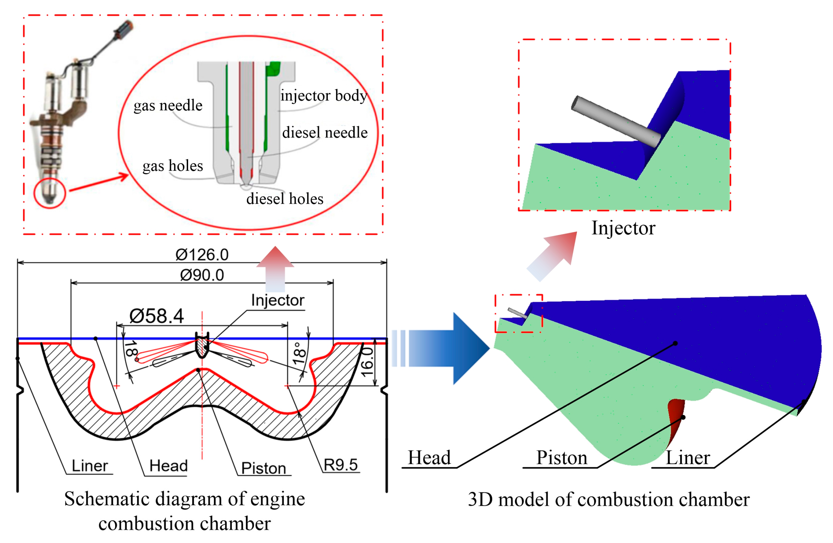
2.1. Experimental Setup

In order not to be limited by the hardware of the test engine (injection pressure) and to better reveal the mechanism of concentration and temperature-stratified combustion technology, numerical simulation is the main research method. A six-cylinder, 11.596 L diesel–NG dual fuel engine was used for the simulation model validation and simulation study. The engine and fuel system specifications are shown in Table 1. The HPDI fuel system was adopted, and a high-pressure common-rail pump provided diesel to the engine fuel system. The diesel rail pressure is regulated through the inlet metering valve on the diesel pump, and the natural gas fuel rail pressure can be adjusted through GCM based on the diesel injection pressure. The HPDI injector is a dual-fuel concentric needle injector with separate needles for the holes. Gas and diesel injection can be independently controlled, and the relative timing and injection duration can be changed. Detail specifications of the engine and fuel system can be seen in the literature [26,27,28]. The diesel and NG were directly injected into the cylinder, and the injection pressure of diesel was 10 bar higher than that of NG. Figure 1 shows the schematic diagram of the engine system. The first cylinder of the engine was the single cylinder test platform, and the other cylinders were the drag cylinders. The obtained data were the average of 200 engine cycles, which can reduce the impact of cyclic variations. In this study, we used only the test results at 25% loads (IMEPg = 5 bar) @1300 rpm; the representative operating conditions were used for combustion and emissions validation for simulation and discussed in the following Section 2.2.2. The experiments were conducted in a stable state of the engine, in which the temperatures of coolant and oil were around 91 ± 0.5 °C, and ambient temperatures and humidity were 25 ± 2 °C and 47 ± 1% respectively.

2.2. Model and Validation

2.2.1. Simulation Model

In order to examine the combustion process, concentration and temperature spatial distributions of the mixture in the cylinder, the multidimensional computational fluid dynamic simulation was conducted by the CONVERGE 2.3 solver. Table 2 shows several important physical and chemical sub-models that were used in this work. Choosing the RANS RNG k- ε model for turbulent flow calculation in the cylinder could simulate transient flow with a reasonable computational time [29]. The Han and Reitz model was chosen as the heat transfer model, which can characterize the effects of gas density and turbulent Prandtl number on the wall boundary layer [30]. In order to simulate the pilot injection process, we used the Kelvin–Helmholtz (KH)/Rayleigh–Taylor (RT) hybrid model to simulate the breakup process of the spray droplet, and we used the Frossling model as the evaporation model [31]. The O’Rourke model was used to describe droplet collision, and spray/wall interactions were considered in the wall film sub-model [32]. Diesel and NG chemistry were simulated by a simplified chemical kinetic mechanism of primary reference fuel oxidation with 45 species and 142 reactions [32,33,34]. The chemical properties of diesel were modeled as n-heptane, while the physical properties of fuel were modelled as tetradecane [34]. An extended Zeldovich NOx model and a phenomenological soot model were also adopted [35]. As described by Baratta [36], the NG injection process was simulated by a multidimensional CFD model. Figure 2 show the modelling diagram. At least 10 cell layers of grid points were set near the nozzle to simulate the gas injection [37]. In this model calculation, it is necessary to provide the characteristics of the gas injector hole and its initial boundary conditions. This method is more accurate than empirical models [32]. The adaptive mesh refinement method (AMR) was used in the simulations to improve the accuracy of solutions. Moreover, the computational mesh grids were refined according to velocity, temperature, and species. In this paper, the diesel spray, gas jet model, combustion and emissions of engine had been validated so as to verify the applicability of those models. Further studies and analyses can be undertaken on the basis of this computational platform.

2.2.2. Model Validation

(1)
Diesel spray validation
The physical properties of 1,3 dimethylnaphthalene (1,3-DMN) are similar to diesel, especially regarding the evaporating rate, boiling point and viscosity. The 1,3-DMN spray experiment of Moon was used for diesel spray validation [38]. Table 3 exhibits the initial conditions of experiment and simulation. Figure 3a displays the concentration distribution of the fuel evaporating phase in the simulation and Moon’s experiment. In Figure 3b, the simulated spray penetration and air entrainment rate are in good agreement with the experiment. By comparing with the experiment data of Moon, the diesel spray model established in this paper can accurately reflect the liquid spray process.
(2)
NG spray model validation
The model validation of the NG spray mainly included free jet and impinging jet processes. This study validated the NG free jet process using experiment data from Ouellette [39], and that experiment data was also adopted by B.Yadollahi [40]. In the simulation, the NG injection pressure and temperature are 150 bar and 350 K, the chamber pressure and temperature are 50 bar and 850 K, and other boundary conditions are also the same as Ouellette [39]. Figure 4 shows the jet tip penetration between simulation and experiment, demonstrating excellent consistency. Yu’s impinging test [41] was used to validate the impinging jet model, and the initial conditions of simulation and test are shown in Table 4. The 3D model of simulation and the impingement schematic of Yu’s experiment are shown in Figure 5. As shown in Figure 6, the simulated gas jet has a good consistency with the experimental jet profile except for some subtle differences in small-scale turbulent structures.
(3)
Combustion and emissions validation
The combustion chamber and 3D simulation model of the NG–diesel engine are illustrated in Figure 7. According to the number of the injector holes (nine diesel holes and nine NG holes, evenly distributed), an engine sector of 40° was selected as the computation domain for reducing the calculation time. In the study, the AMR algorithm was used to generate computational grids, and the minimum and maximum cell size are 0.0625 mm and 4 mm, respectively. We adopted a fixed embedding near the gas injector to improve the computational stability of that region. The engine was operated at 1300 r/min, 5 bar IMEPg. For all cases, the simulation calculation began at intake valve closing (IVC = −146 °CA ATDC) and ended at an exhaust valve opening (EVO = 131 °CA ATDC). The temperatures of the cylinder, cylinder head, and piston wall boundaries were set to 500, 450, and 500 K, respectively. The in-cylinder charge temperature was set to 353 K at IVC. Moreover, the NG blend contained 98.8% CH4, 0.4% C2H6, and 0.8% N2, which was consistent with the available chemical kinetic mechanism.
In order to validate the simulation model for combustion process and emissions, experimental tests on the dual-fuel engine (in Section 2.1) were provided. Experiment_01 and experiment_02 were stratified combustion, the engine speeds were 1300 r/min, IMEPgs were about 5 bar, and the gas pressure was 135 bar. In experiment_01, the SOI of NG was −10 °CA ATDC, and the SOI of diesel was −30 °CA ATDC. In experiment_02, the SOI of NG was −30 °CA ATDC, and the SOI of diesel was −46 °CA ATDC. The initial conditions of the simulations were set to be the same as that of the experiment. The cylinder pressure and heat release rate obtained from each experiment and simulation maintain good consistency, which can be found in Figure 8. In Figure 9, although there are some numerically differences between the predicted and experimental values of CO, uHC and NOx emissions, the trend fits well. Meanwhile, the simulation also calibrated the experiment of Neely et al. [26] and applied it to the same engine. The experiment was at 1000 r/min, 12 bar BMEP, under DI2 operation with modified nozzles. Moreover, the SOI of NG was −30 °CA ATDC, and the SOI of diesel was −7 °CA ATDC, so the mixture combustion was also stratified combustion. Figure 8 shows that the in-cylinder pressures and AHRR of simulation are in good agreement with the published experimental results. Unfortunately, no specific emissions data were given in their study. Therefore, the model of this study is accurate enough to predict the combustion process and emission characteristics of the engine.

2.3. Definition

In order to facilitate the later description, a few definitions are introduced and explained in detail. The react ratio can be defined as follows:
r e a c t   r a t i o = 2 n C + 1 2 n H n O
The nC, nH, and nO represent the number of carbon, hydrogen, and oxygen atoms of the reactants, but they do not include CO2 and H2O [32].
The pilot diesel ratio (PDR) is calculated as
PDR = m diesel L H V diesel m diesel L H V diesel + m n g L H V n g × 100
where mdiesel and mng are the quantity of diesel fuel and NG, LHVdiesel and LHVng are the low heat value of diesel and NG [16,32,42].
The first law of energy conservation equation in the engine is expressed in Equation (3)
W i g Q f u e l + Q H T Q f u e l + Q comb Q fuel + Q e x h Q f u e l = 100 %
Qfuel represents the total cycle fuel energy, Wi-g is the network during the compression and expansion strokes, QHT is the energy lost by heat transfer, Qcomb is the energy lost by combustion due to the formation of incomplete combustion products (CO and UHCs), and Qexh is the energy lost by exhaust, which refers to the enthalpy difference between the intake and exhaust matter [28].
Gross indicated thermal efficiency (ITEg) [28,35] is defined as
I T E g = W i g Q f u e l × 100 %
Heat transfer loss (HTL) is obtained as
H T L = Q H T Q f u e l × 100 %
Exhaust loss (EL) is calculated as
E L = Q e x h Q f u e l = Q o u t Q i n Q f u e l × 100 %
Q i n and Q o u t are the energy of inflow and outflow in the system, respectively.
Combustion loss (CL) [28,43] is defined as
C L = Q u n b Q f u e l × 100 %
The CA10, CA50, and CA90 are the crankshaft angles corresponding to the accumulated heat release, which reach 10%, 50%, and 90% of the total chemical heat release, respectively [44].

3. Results and Discussion

3.1. Organization of Different Stratified Mixture

In this work, different stratified combustion processes are achieved by controlling the pressures, timings, and times of diesel and NG injections by the numerical simulation method. Four typical operating cases have been selected and analyzed in detail for their good or individual engine performances. Specifications of the pressure, timing, and times of diesel and NG injections and a set of input parameters at the typical operating cases are provided in Table 5. The injection sequence of diesel and NG is shown in Figure 10. In Table 5, Pin is the intake pressure, FSOIdiesel (°CA ATDC) is the first start of diesel injection timing, FSOIng (°CA ATDC) is the first start of NG injection timing, and Fng (%) is the proportion of the first NG injection, while SSOIdiesel (°CA ATDC) is the second start of diesel injection timing, and SSOIng (°CA ATDC) is the second start of NG injection timing.
To illustrate the stratification of the mixture in the combustion process at typical engine operating cases, the mass percentage distribution of unburned fuel at different react ratios is calculated at CA10 and CA50, which is shown in Figure 11. Based on previous studies, when the NG mixture’s react ratio is below 0.7 or above 1.25, it is not beneficial to flame propagation for too lean or too rich mixtures. Therefore, when the NG mixture’s react ratio is between 0.7 and 1.25, it is a moderate react ratio from the perspective of combustion [36,45,46]. In case 1, the pressures and timings of diesel and NG injection are lower and earlier than that of other typical operating cases, respectively. The percentages of an unburned NG mixture with a moderate react ratio are 61.7 and 42.1 at CA10 and CA50. In case 2, the timings of diesel and NG injection are close to the TDC, but the pressures of diesel and NG injection are over-high (600/590 bar). Thus, the percentages of unburned lean NG mixture are 67.9 and 94.0 at CA10 and CA50, respectively. For case 3, the pressures of diesel and NG injection are higher than that of case 1 while maintaining the same NG injection timing. The percentages of unburned NG mixture with a lean react ratio are 66.7 and 98.6 at CA10 and CA50, respectively. Due to split injections of diesel and NG, the stratification of the in-cylinder charge’s concentration and temperature could be further changed. In case 4, the pressures of diesel and NG injection are lower than those of cases 2 and case 3. Furthermore, the timing of NG injection is also close to TDC. Therefore, over half of the unburned NG mixture distributes at a rich react ratio at CA10 and CA50. Different stratifications of the mixture in the cylinder could be organized by controlling the pressure, timing, and duration of diesel and NG injections. Moreover, according to the react ratio distributions of the unburned mixture during the combustion process, stratified combustions can be classified into moderate (case 1), lean (case 2, 3), and rich (case 4) stratified combustion mode.

3.2. Combustion in Moderate React Ratio Mixture (Case 1)

In order to investigate the combustion characteristic of moderate stratified combustion mode, Figure 12 demonstrates the detailed concentration and temperature spatial distributions of the mixture in case 1. The longitudinal cut-plane represents the center section of the combustion chamber, the cross cut-plane is used to capture the first ignition of the NG mixture, and the icon of a red coil is the diesel or diesel-combustion high-temperature regions. As shown in Figure 12, when the crank angle is −17 °CA ATDC, the react ratio and local maximum temperature of the pilot diesel mixture are 0.44 and 1400 K, respectively. At −16 °CA ATDC, the pilot diesel has almost completely burned, and the maximum combustion temperature is 2100 K. It means that the pilot diesel has completed mixing with air and started the premixed combustion, and then it ignited the NG mixture around at −17 °CA ATDC.
From Figure 12, NG is directly injected into the cylinder at −25 °CA ATDC and then collides with the combustion chamber’s throat. At −17 °CA and −16 °CA ATDC, under the influences of high momentum NG spray and the combustion chamber wall, stable vortexes are formed in the front of the NG jet. At −14 °CA ATDC, there is a rich NG-stratified mixture with a react ratio of over 1.0, but the NG combustion is firstly taking place in a lean mixture with a react ratio of 0.5. The combustion temperature is below 2200 K. In case 1, most of the NG mixture burns with a moderate react ratio. However, at −8 °CA ATDC, some NG-stratified mixtures with a react ratio of 0.8 burn, and the combustion temperature is higher than 2200 K. NOx will be generated due to the high combustion temperature [47,48]. It can be obtained that through controlling the pressure, timing, and duration of pilot diesel and NG injections, NG combustion can occur continuously in a stratified mixture with a moderate react ratio. Furthermore, NG combustion should happen in the stratified mixture with a react ratio below 0.8 to avoid NOx production. By the late part of combustion, the NG mixture becomes leaner and leaner. In Figure 12, at 0 °CA and 5 °CA ATDC, the react ratios of unburned NG-stratified mixtures in the cylinder are lower than 0.2, but it still burns due to the surrounding high-temperature charge. Therefore, ensuring that the over-lean NG-stratified mixture is around a high-temperature charge would be very important to eliminate UHC emissions in an NG engine.
Figure 13 shows the cylinder pressure and heat release rate of cases 1–4. In case 1, the cylinder pressure peak is the highest among all the test cases due to an advanced combustion phase. There is a moderate peak of heat release rate when the pilot diesel burns and the NG burns rapidly with a high heat release rate. The energy distributions and emissions of cases 1–4 are calculated and shown in Figure 14. In case 1, the indicated specific emissions of NOx (ISNOx) are 3.2 g/kWh, the indicated specific emissions of UHC (ISUHC) are 1.2 g/kWh, and the ITEg is 47.6%. The objective of low UHC emissions and high thermal efficiency is realized in the moderate react ratio mixture combustion.

3.3. Combustion in Lean React Ratio Mixture (Case 2, 3)

The concentration and temperature distributions of the mixture in case 2 are shown in Figure 15. At −4 °CA ATDC, the pilot diesel has had a chemical reaction, the local temperature is 1550 K, and the maximum react ratio is over 1.0. At −3 °CA ATDC, the combustion temperature of the pilot diesel is over 2700 K. Meanwhile, the NG mixture which is around the pilot diesel burned region burns. At 16 °CA ATDC, the react ratio of the unburned NG-stratified mixture is below 0.4, and the nearby charge temperature is below 1000 K. So, the combustion of the unburned NG-stratified mixture stagnates. Thus, the NG-stratified mixture should burn under the condition of a react ratio above 0.4 to avoid incomplete combustion and low CL. In case 2, due to the high fuel injection pressure, the vortex entrains more surrounding air than case 1. It promotes the dilution of NG. The whole NG mixtures burn at a react ratio below 0.8, of which the combustion temperature is lower than 2200 K. Hence, pilot diesel combustion is the cause of NOx production.
In case 3, split injections of pilot diesel and NG have been performed on the diesel–NG dual-fuel engine. Figure 16 illustrates the concentration and temperature distributions of the mixture in case 3. At −15 °CA ATDC, it can be seen that a local mixture (area A) with a temperature 1300 K and react ratio of 0.3 appear in the cylinder. Due to the vortex motion, the primary fuel is the first-injection pilot diesel in the local mixture. The second-injection pilot diesel burns at −10 °CA ATDC, while the combustion temperature is over 2700 K. It means that multiple injections of the pilot diesel can form more than one high-temperature region (area A and B). Due to the small amount of the second-injection pilot diesel (PDR = 6.6%), the charge temperature (in area B) decreases rapidly. The combustion temperature was lower than 2300 K at −7 °CA ATDC.
As shown in Figure 16, a split injection of NG is applied. At −7 °CA ATDC, the second-injection NG approaches the first-injection NG region. Part of second-injection NG impinges the wall and touches the burned high-temperature charge, and then it ignites gradually. At 0 °CA ATDC, the combustible NG-stratified mixture is burning with a react ratio of 0.45 in the longitudinal section. At 8 °CA ATDC, the react ratio of the unburned NG-stratified mixture is lower than 0.4. However, due to the surrounding charge with a temperature of 1200 K, it still burns. In case 3, most of the NG-stratified mixture reacts with a lean react ratio. Compared to the combustion process of case 2, the split injections of pilot diesel and NG can further change the temperature stratification. Moreover, it reveals that controlling appropriate temperature stratification can increase the reactivity of the over-lean NG-stratified mixture, and high combustion efficiency can be achieved.
In case 2, from Figure 13, the heat release rate of pilot diesel is highest compared with that in other cases. The subsequent NG combustion is slow. From Figure 14, the ISNOx emissions are 1.3 g/kWh, the ISUHC emissions are 62.0 g/kWh, and the CL is approximately 30%. In case 3, from Figure 13, the heat release rate is slow, and the combustion duration is long for the lean NG-stratified mixture combustion. In Figure 14, the ISNOx emissions are 0.6 g/kWh, the ISUHC emissions are 1.6 g/kWh, and ITEg is 47.9%. In the comparisons of cases 2 and 3, controlling the concentration and temperature stratification of the mixture in the cylinder, high thermal efficiency and low emissions can be achieved simultaneously in the lean react ratio mixture combustion.

3.4. Combustion in Rich React Ratio Mixture (Case 4)

The concentration and temperature distributions of the mixture in case 4 are presented in Figure 17. At −12 °CA ATDC, the pilot diesel undergoes diffusion combustion, and the maximum combustion temperature is over 2700 K. The NG is directly injected into the pilot diesel burned region at −5 °CA ATDC. It can be seen that the NG-stratified mixture burns at −2 °CA ATDC, and the combustion temperature is higher than 2700 K. It should be noted that most of the NG-stratified mixture burns with a rich react ratio, and unburned fuel is in a high-temperature environment. During the entire combustion process, a continuous high-temperature region (over 2200 K) is observed in the cylinder. From Figure 13 and Figure 14, in case 4, the heat release rate of NG is the highest among all cases. The ISUHC emissions are 0.7 g/kWh, the ISNOx emissions are 10.6 g/kWh, and ITEg is 47.0%. It can be obtained that low UHC emissions and high combustion efficiency can be achieved in the rich react ratio mixture combustion. However, a large amount of NOx will be generated.

4. Conclusions

In the present study, the technology of concentration and temperature-stratified combustion (CTSC) is proposed to improve thermal efficiency and reduce UHC emissions at idle and low NG engine loads. In order to reveal the essences of stratified combustion control technology, detail concentration and temperature distributions of the mixture have been analyzed and discussed. Based on the obtained results, the main conclusions are drawn as follows:
(1)
At low engine loads, stratified combustion increased the reactivity of combustible mixture for concentration and temperature stratification. Different stratified combustion can be organized by controlling pressures, timings, and durations of diesel and NG injections. According to the react ratio distributions of the unburned mixture during the combustion process, typical stratified combustion can be classified into moderate, lean, and rich stratified combustion mode.
(2)
Combining with the concentration and temperature stratification of the mixture, high thermal efficiency and low emissions can be realized simultaneously in stratified combustion. The concept of CTSC was put forward to suggest that more mixtures should burn with the react ratio of 0.4 to 0.8 for low NOx emissions, low UHC emissions and rapid combustion. The proper temperature stratification should provide a high-temperature charge around the over-lean NG-stratified mixture to improve combustion efficiency and reduce UHC emissions.
(3)
Stratified combustion strategy was adopted at low NG engine load operation (IMEPg = 5 bar), of which the PDR was 11%, and ITEg was above 47.0%. The drawbacks of significant cycle-to-cycle variations of the NG engine at low load can be overcome. Furthermore, ISUHC values were below 1.6 g/kWh, and ISNOx values were below 0.6 g/kWh.

Author Contributions

Conceptualization, M.Z. and W.S.; methodology, M.Z.; software, M.Z.; validation, M.Z., Z.J.; formal analysis, M.Z.; investigation, M.Z.; resources, W.S.; data curation, Z.J.; writing—original draft preparation, M.Z.; writing—review and editing, W.S.; visualization, Z.J.; supervision, W.S.; project administration, W.S.; funding acquisition, W.S. All authors have read and agreed to the published version of the manuscript.

Funding

The work was supported the National Key R&D Program of China (2017YFE0102800), by the Natural Science Foundation of Tianjin through its project funding No. 19JCYBJC21200, and by the China Postdoctoral Science Foundation Grant No. 2018 M631737.

Data Availability Statement

The datasets presented in this article are not readily available due to privacy.

Conflicts of Interest

The authors declare no conflict of interest.

Nomenclature

NGnatural gas
UHCunburned hydrocarbon
CO2carbon dioxide
EGRexhaust gas recirculation
PDRpilot diesel ratio
COcarbon monoxide
TDCtop dead center
ATDCafter the top dead center
IVCintake valve closing
EVOexhaust valve opening
SOIstart of injection
AHRRapparent heat release rate
HTLheat transfer loss
ELexhaust loss
CLcombustion loss
Pinintake pressure
HPDIhigh-pressure direct injection
NOxnitrogen oxides
IMEPggross indicated mean effective pressure
BMEPbrake mean effective pressure
ITEgindicated thermal efficiency
CTSCconcentration and temperature-stratified combustion
ISUHCindicated specific emissions of UHC
ISNOxindicated specific emissions of nitrogen oxide
HCCIhomogeneous charge compression ignition
DIDFdiesel-ignited dual fuel
RCCIreactivity-controlled compression ignition
Pnginjection pressure of NG
Pdieselinjection pressure of diesel
FSOIdieselfirst start of diesel injection timing
SSOIdieselsecond start of diesel injection timing
FSOIngfirst start of NG injection timing
SSOIngsecond start of NG injection timing
Fngproportion of the first NG injection
DI2co-direct injection of NG and diesel fuel
CH4methane

References

  1. Fasching, P.; Sprenger, F.; Eichlseder, H. Experimental Optimization of a Small Bore Natural Gas-Diesel Dual Fuel Engine with Direct Fuel Injection. SAE Int. J. Engines 2016, 9, 1072–1086. [Google Scholar] [CrossRef]
  2. Yu, H.; Su, W. Numerical Study on a High Efficiency Gasoline Reformed Molecule HCCI Combustion Using Exergy Analysis; SAE Technical Paper 2017-01-0735; SAE International: Warrendale, PA, USA, 2017. [Google Scholar] [CrossRef]
  3. Papagiannakis, R.; Kotsiopoulos, P.; Zannis, T.; Yfantis, E.; Hountalas, D.; Rakopoulos, C. Theoretical study of the effects of engine parameters on performance and emissions of a pilot ignited natural gas diesel engine. Energy 2010, 35, 1129–1138. [Google Scholar] [CrossRef]
  4. Lu, X.; Han, D.; Huang, Z. Fuel design and management for the control of advanced compression-ignition combustion modes. Prog. Energy Combust. Sci. 2011, 37, 741–783. [Google Scholar] [CrossRef]
  5. Christensen, M.; Johansson, B.; Amnéus, P.; Mauss, F. Supercharged Homogeneous Charge Compression Ignition; SAE Technical Paper 980787; SAE International: Warrendale, PA, USA, 1998. [Google Scholar] [CrossRef]
  6. Kuzuyama, H.; Machida, M.; Akihama, K.; Inagaki, K.; Ueda, M. A Study on Natural Gas Fueled Homogeneous Charge Compression Ignition Engine—Expanding the Operating Range and Combustion Mode Switching; SAE Technical Paper 2007-01-0176; SAE International: Warrendale, PA, USA, 2007. [Google Scholar] [CrossRef]
  7. Handford, D.I.; Checkel, M.D. Extending the Load Range of a Natural Gas HCCI Engine Using Direct Injected Pilot Charge and External EGR; SAE Technical Paper 2009-01-1884; SAE International: Warrendale, PA, USA, 2009. [Google Scholar] [CrossRef]
  8. Shim, E.; Park, H.; Bae, C. Intake air strategy for low HC and CO emissions in dual-fuel (CNG-diesel) premixed charge compression ignition engine. Appl. Energy 2018, 225, 1068–1077. [Google Scholar] [CrossRef]
  9. Yousefi, A.; Birouk, M. Investigation of natural gas energy fraction and injection timing on the performance and emissions of a dual-fuel engine with pre-combustion chamber under low engine load. Appl. Energy 2017, 189, 492–505. [Google Scholar] [CrossRef]
  10. Vávra, J.; Bortel, I.; Takáts, M.; Diviš, M. Emissions and performance of diesel–natural gas dual-fuel engine operated with stoichiometric mixture. Fuel 2017, 208, 722–733. [Google Scholar] [CrossRef]
  11. Li, D.; Liu, Z.; Wu, Y. Experimental and theoretical analysis of the combustion process at low loads of a diesel natural gas dual-fuel engine. Energy 2016, 94, 728–741. [Google Scholar] [CrossRef]
  12. Mikulski, M.; Balakrishnan, P.R.; Hunicz, J. Natural gas-diesel reactivity controlled compression ignition with negative valve overlap and in-cylinder fuel reforming. Appl. Energy 2019, 254, 113638. [Google Scholar] [CrossRef]
  13. Ansari, E.; Shahbakhti, M.; Naber, J. Optimization of performance and operational cost for a dual mode diesel-natural gas RCCI and diesel combustion engine. Appl. Energy 2018, 231, 549–561. [Google Scholar] [CrossRef]
  14. Li, Y.; Jia, M.; Xu, L.; Bai, X.-S. Multiple-objective optimization of methanol/diesel dual-fuel engine at low loads: A comparison of reactivity controlled compression ignition (RCCI) and direct dual fuel stratification (DDFS) strategies. Fuel 2020, 262, 116673. [Google Scholar] [CrossRef]
  15. Li, J.; Yang, W.; Zhou, D. Review on the management of RCCI engines. Renew. Sustain. Energy Rev. 2017, 69, 65–79. [Google Scholar] [CrossRef]
  16. Poorghasemi, K.; Saray, R.K.; Ansari, E.; Irdmousa, B.K.; Shahbakhti, M.; Naber, J.D. Effect of diesel injection strategies on natural gas/diesel RCCI combustion characteristics in a light duty diesel engine. Appl. Energy 2017, 199, 430–446. [Google Scholar] [CrossRef]
  17. Di Blasio, G.; Belgiorno, G.; Beatrice, C.; Fraioli, V.; Migliaccio, M. Experimental Evaluation of Compression Ratio Influence on the Performance of a Dual-Fuel Methane-Diesel Light-Duty Engine. SAE Int. J. Engines 2015, 8, 2253–2267. [Google Scholar] [CrossRef]
  18. Yousefi, A.; Guo, H.; Birouk, M.; Liko, B. On greenhouse gas emissions and thermal efficiency of natural gas/diesel dual-fuel engine at low load conditions: Coupled effect of injector rail pressure and split injection. Appl. Energy 2019, 242, 216–231. [Google Scholar] [CrossRef]
  19. Forster, P.; Ramaswamy, V.; Artaxo, P.; Berntsen, T.; Betts, R.; Fahey, D.W.; Haywood, J.; Lean, J.; Lowe, D.C.; Myhre, G.; et al. Changes in atmospheric constituents and in radiative forcing. In 4th Assessment Report of the IPCC WG1: The Physical Science Basis; Cambridge University Press: Cambridge, UK, 2007. [Google Scholar]
  20. McTaggart-Cowan, G. Pollutant Formation in a Gaseous-Fuelled, Direct Injection Engine. Ph.D. Thesis, University of British Columbia, Vancouver, BC, Canada, 2006. [Google Scholar]
  21. Faghani, E.; Patychuk, B.; McTaggart-Cowan, G.; Rogak, S. Soot Emission Reduction from Post Injection Strategies in a High Pressure Direct Injection Natural Gas Engine. In Proceedings of the 11th International Conference on Engines & Vehicles, Napoli, Italy, 15–19 September 2013; SAE Technical Paper 2013-24-0114. Available online: https://saemobilus.sae.org/content/2013-24-0114 (accessed on 8 August 2024).
  22. Mctaggart-Cowan, G.; Mann, K.; Huang, J.; Singh, A.; Patychuk, B.; Zheng, Z.X.; Munshi, S. Direct Injection of Natural Gas at up to 600 Bar in a Pilot-Ignited Heavy-Duty Engine. SAE Int. J. Engines 2015, 8, 981–996. [Google Scholar] [CrossRef]
  23. Faghani, E.; Kheirkhah, P.; Mabson, C.W.; McTaggart-Cowan, G.; Kirchen, P.; Rogak, S. Effect of Injection Strategies on Emissions from a Pilot-Ignited Direct-Injection Natural-Gas Engine—Part I: Late Post Injection; SAE Technical Paper 2017-01-0774; SAE International: Warrendale, PA, USA, 2017. [Google Scholar] [CrossRef]
  24. Faghani, E.; Kheirkhah, P.; Mabson, C.W.; McTaggart-Cowan, G.; Kirchen, P.; Rogak, S. Effect of Injection Strategies on Emissions from a Pilot-Ignited Direct-Injection Natural-Gas Engine—Part II: Slightly Premixed Combustion; SAE Technical Paper 2017-01-0763; SAE International: Warrendale, PA, USA, 2017. [Google Scholar] [CrossRef]
  25. Florea, R.; Neely, G.D.; Abidin, Z.; Miwa, J. Efficiency and Emissions Characteristics of Partially Premixed Dual-Fuel Combustion by Co-Direct Injection of NG and Diesel Fuel (DI2); SAE Technical Paper 2016-01-0779; SAE International: Warrendale, PA, USA, 2017. [Google Scholar] [CrossRef]
  26. Neely, G.D.; Florea, R.; Miwa, J.; Abidin, Z. Efficiency and Emissions Characteristics of Partially Premixed Dual-Fuel Combustion by Co-Direct Injection of NG and Diesel Fuel (DI2)-Part 2; SAE Technical Paper 2017-01-0766; SAE International: Warrendale, PA, USA, 2017. [Google Scholar] [CrossRef]
  27. Rochussen, J.; Yeo, J.; Kirchen, P. Effect of Fueling Control Parameters on Combustion and Emissions Characteristics of Diesel-Ignited Methane Dual-Fuel Combustion; SAE Technical Paper 2016-01-0792; SAE International: Warrendale, PA, USA, 2016. [Google Scholar] [CrossRef]
  28. Su, W.; Yu, W. Effects of mixing and chemical parameters on thermal efficiency in a partly premixed combustion diesel engine with near-zero emissions. Int. J. Engine Res. 2012, 13, 188–198. [Google Scholar] [CrossRef]
  29. Han, Z.; Reitz, R.D. Turbulence Modeling of Internal Combustion Engines Using RNG κ-ε Models. Combust. Sci. Technol. 1995, 106, 267–295. [Google Scholar] [CrossRef]
  30. Han, Z.; Reitz, R.D. A temperature wall function formulation for variable-density turbulent flows with application to engine convective heat transfer modeling. Int. J. Heat Mass Transf. 1997, 40, 613–625. [Google Scholar] [CrossRef]
  31. Li, Y.; Jia, M.; Chang, Y.; Kokjohn, S.L.; Reitz, R.D. Thermodynamic energy and exergy analysis of three different engine combustion regimes. Appl. Energy 2016, 180, 849–858. [Google Scholar] [CrossRef]
  32. Nie, X.; Su, W. Numerical Study of Ignition Core Formation and the Effects on Combustion in a Pilot Ignited NG Engine; SAE Technical Paper 2017-01-2273; SAE International: Warrendale, PA, USA, 2017. [Google Scholar] [CrossRef]
  33. Ra, Y.; Reitz, R.D. A reduced chemical kinetic model for IC engine combustion simulations with primary reference fuels. Combust. Flame 2008, 155, 713–738. [Google Scholar] [CrossRef]
  34. Li, Y.; Guo, H.; Li, H. Evaluation of Kinetics Process in CFD Model and Its Application in Ignition Process Analysis of a Natural Gas-Diesel Dual Fuel Engine; SAE Technical Paper 2017-01-0554; SAE International: Warrendale, PA, USA, 2017. [Google Scholar] [CrossRef]
  35. Heywood, J.B. Internal Combustion Engine Fundamentals; McGraw-Hill: New York, NY, USA, 1988. [Google Scholar]
  36. Baratta, M.; Catania, A.E.; Spessa, E.; Herrmann, L.; Roessler, K. Multi-Dimensional Modeling of Direct Natural-Gas Injection and Mixture Formation in a Stratified-Charge SI Engine with Centrally Mounted Injector. SAE Int. J. Engines 2009, 1, 607–626. [Google Scholar] [CrossRef]
  37. Li, Y.; Kirkpatrick, A.; Mitchell, C.; Willson, B. Characteristic and Computational Fluid Dynamics Modeling of High-Pressure Gas Jet Injection. Mod. Hosp. 2004, 126, 192–197. [Google Scholar] [CrossRef]
  38. Moon, S.; Matsumoto, Y.; Nishida, K. Entrainment, Evaporation and Mixing Characteristics of Diesel Sprays around End-of-Injection; SAE Technical Paper, 2009-01-0849; SAE International: Warrendale, PA, USA, 2009. [Google Scholar] [CrossRef]
  39. Ouellette, P.; Hill, P.G. Turbulent Transient Gas Injections. J. Fluids Eng. 2000, 122, 743–752. [Google Scholar] [CrossRef]
  40. Yadollahi, B.; Boroomand, M. The effect of combustion chamber geometry on injection and mixture preparation in a CNG direct injection SI engine. Fuel 2013, 107, 52–62. [Google Scholar] [CrossRef]
  41. Yu, J.; Vuorinen, V.; Hillamo, H.; Sarjovaara, T.; Kaario, O.; Larmi, M. An experimental investigation on the flow structure and mixture formation of low pressure ratio wall-impinging jets by a natural gas injector. J. Nat. Gas Sci. Eng. 2012, 9, 1–10. [Google Scholar] [CrossRef]
  42. Ansari, E.; Menucci, T.; Shahbakhti, M.; Naber, J. Experimental investigation into effects of high reactive fuel on combustion and emission characteristics of the Diesel—Natural gas Reactivity Controlled Compression Ignition engine. Appl. Energy 2019, 239, 948–956. [Google Scholar] [CrossRef]
  43. Sitkei, G. Heat Transfer and Thermal Loading in Internal Combustion Engines; Akademiai Kaido: Budapest, Hungary, 1974. [Google Scholar]
  44. Zhou, L.; Hua, J.; Liu, F.; Liu, F.; Feng, D.; Wei, H. Effect of internal exhaust gas recirculation on the combustion characteristics of gasoline compression ignition engine under low to idle conditions. Energy 2018, 164, 306–315. [Google Scholar] [CrossRef]
  45. Zhang, X.; Wang, T.; Zhang, J. Numerical analysis of flow, mixture formation and combustion in a direct injection natural gas engine. Fuel 2020, 259, 116268. [Google Scholar] [CrossRef]
  46. Baratta, M.; Misul, D. Development and assessment of a new methodology for end of combustion detection and its application to cycle resolved heat release analysis in IC engines. Appl. Energy 2012, 98, 174–189. [Google Scholar] [CrossRef]
  47. Akihama, K.; Takatori, Y.; Inagaki, K.; Sasaki, S.; Dean, A.M. Mechanism of the Smokeless Rich Diesel Combustion by Reducing Temperature; SAE Technical Paper 2001-01-0655; SAE International: Warrendale, PA, USA, 2001. [Google Scholar] [CrossRef]
  48. Kamimoto, T.; Bae, M.-H. High Combustion Temperature for the Reduction of Particulate in Diesel Engines; SAE Technical Paper 880423; SAE International: Warrendale, PA, USA, 1988. [Google Scholar] [CrossRef]
Figure 1. Schematic of the experimental setup.
Energies 17 04351 g001
Figure 2. Schematic diagram of single nozzle gas injection model.
Energies 17 04351 g002
Figure 3. Comparison of results between simulation and Moon’s experiment: (a) concentration distribution, (b) spray penetration and ratio of air entrainment.
Energies 17 04351 g003
Figure 4. Penetration for simulation and experiment result.
Energies 17 04351 g004
Figure 5. Three-dimensional (3D) model of simulation and impingement schematic of Yu’s experiment [41].
Energies 17 04351 g005
Figure 6. Simulation and Yu’s experiment results of impinging jet (a) 1.5 ms after SOI, (b) 1.7 ms after SOI, (c) 2.8 ms after SOI.
Energies 17 04351 g006
Figure 7. Engine combustion chamber and geometric model.
Energies 17 04351 g007
Figure 8. The validation of pressure and AHRR for stratified combustion.
Energies 17 04351 g008
Figure 9. The validation of emissions for stratified combustion.
Energies 17 04351 g009
Figure 10. The injection sequence of diesel and NG in typical engine operating cases.
Energies 17 04351 g010
Figure 11. Mass percentage distribution of unburned fuel at different react ratios of typical engine operating cases (a) at CA10, (b) at CA50.
Energies 17 04351 g011
Figure 12. Concentration and temperature distributions of the mixture in case 1: (a) distribution of react ratio, (b) distribution of temperature.
Energies 17 04351 g012
Figure 13. Pressure and heat release rate in the cylinder of typical operating cases.
Energies 17 04351 g013
Figure 14. Energy distributions and emissions of typical operating cases (a) energy distributions, (b) emission characteristics.
Energies 17 04351 g014
Figure 15. Concentration and temperature distributions of the mixture in case 2: (a) distribution of react ratio, (b) distribution of temperature.
Energies 17 04351 g015
Figure 16. Concentration and temperature distributions of the mixture in case 3: (a) distribution of react ratio, (b) distribution of temperature.
Energies 17 04351 g016
Figure 17. Concentration and temperature distributions of the mixture in case 4: (a) distribution of react ratio, (b) distribution of temperature.
Energies 17 04351 g017
Table 1. Engine specifications.
ParametersValues
Base engineWP12
Cylinder arrangementI6
Bore/Stroke126/155 mm
Connecting rod length253 mm
Displacement11.596 L
Compression ratio17:1
Inlet valve close timing−146° CA ATDC
Exhaust valve open timing131° CA ATDC
Rated power (KW/rpm)353 KW/2100 rpm
Max torque (Nm/rpm)1970 N·m/1200~1500 rpm
Injection system
[26,27]
Hole number/angleDiesel: 9/18°; Gas: 9/18°
Diesel hole diameter0.17 mm
NG hole diameter0.66 mm
Diesel injection pressure (Pdiesel (bar))≤200 bar
NG injection pressure (Png (bar))Pdiesel − 10 bar
Table 2. Three-dimensional (3D) numerical simulation sub-model.
ModelSub-Model
Turbulence modelRANS RNG k- ε
Heat transfer modelHan and Reitz
Spray modelKH–RT
Turbulent dispersionO’Rourke
Combustion modelSAGE
Chemical kinetic mechanismReitz PRF
NOxExtended Zeldovich NOx
SOOTHiroyasu Soot
Table 3. The initial conditions of experiment and simulation.
MoonSimulation
Injector diameter [mm]0.1350.135
Injection quantity [mg]6.706.70
Injection duration [ms]1.441.44
Injection pressure [MPa]120120
Ambition pressure [MPa]44
Ambition temperature [K]830830
Fuel1,3-DMN C 10 H 6 C H 3 2 n-heptane C 7 H 16
Table 4. Simulation and experiment conditions of impinging jet.
ParametersValues
Gas Injection Pressure (bar)7
Injected GasN2
Ambient Pressure (bar)1
Ambient Temperature (K)293.15
Impinging Distance (mm)33
Impinging Angle (°)83
Table 5. Parameters of typical engine operating conditions at IMEPg = 5 bar, engine speed = 1300 r/min.
CasePng
/bar
Pdiesel
/bar
Pin
/bar
FSOIdiesel
/°CA ATDC
SSOIdiesel
/°CA ATDC
FSOIng
/°CA ATDC
SSOIng
/°CA ATDC
Fng
/%
PRD
/%
11001101.5−38−2510011
25906001.5−7−1510011
32802901.5−35−16−25−88017.6
41001101.5−20−810011
Disclaimer/Publisher’s Note: The statements, opinions and data contained in all publications are solely those of the individual author(s) and contributor(s) and not of MDPI and/or the editor(s). MDPI and/or the editor(s) disclaim responsibility for any injury to people or property resulting from any ideas, methods, instructions or products referred to in the content.

