

Review of Computational Fluid Dynamics in the Design of Floating Offshore Wind Turbines


Abstract
1. Introduction
2. Mechanisms and Dynamics of FOWTs
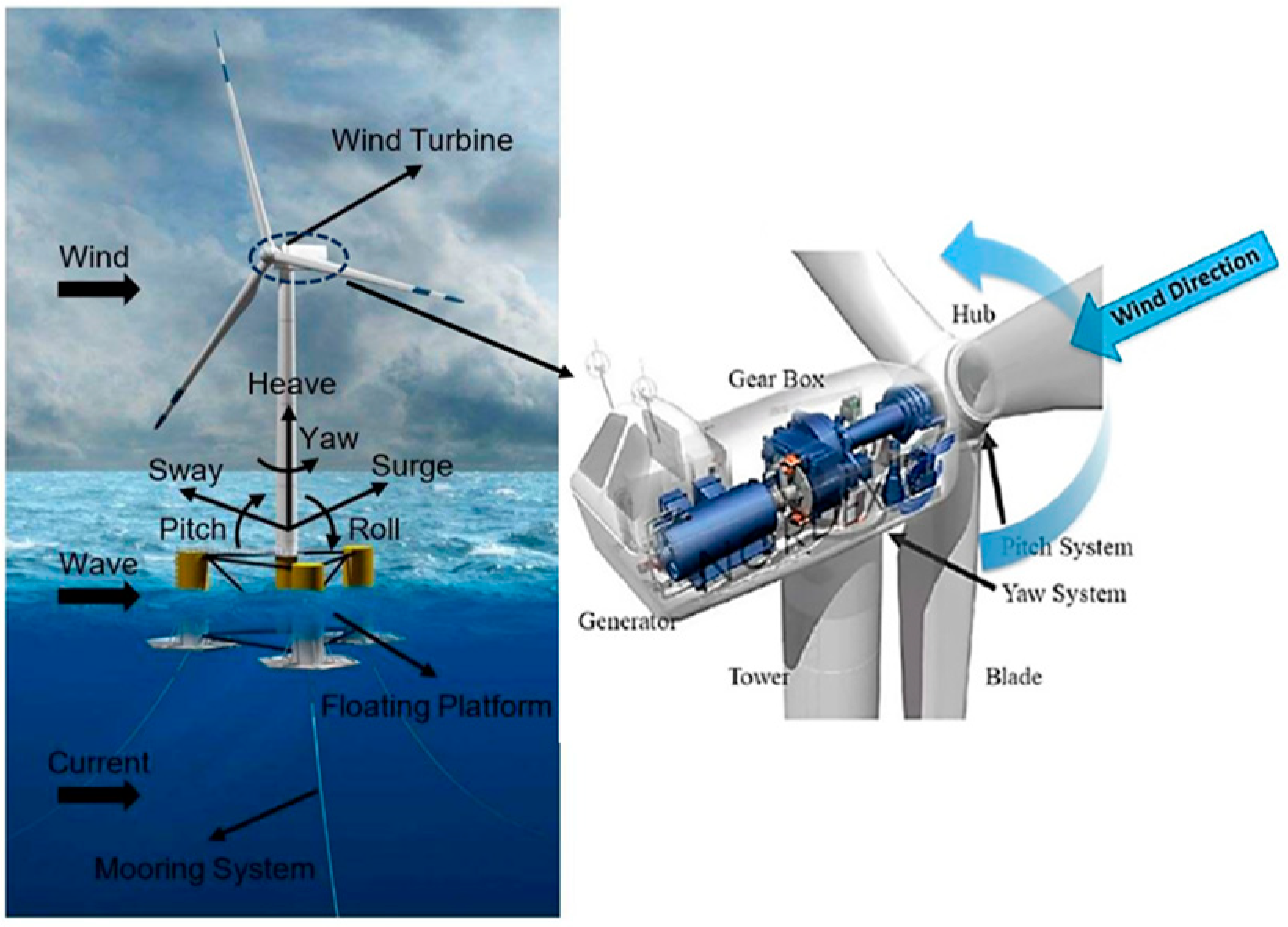
2.1. Overview
2.2. FOWT Assembly and Control System
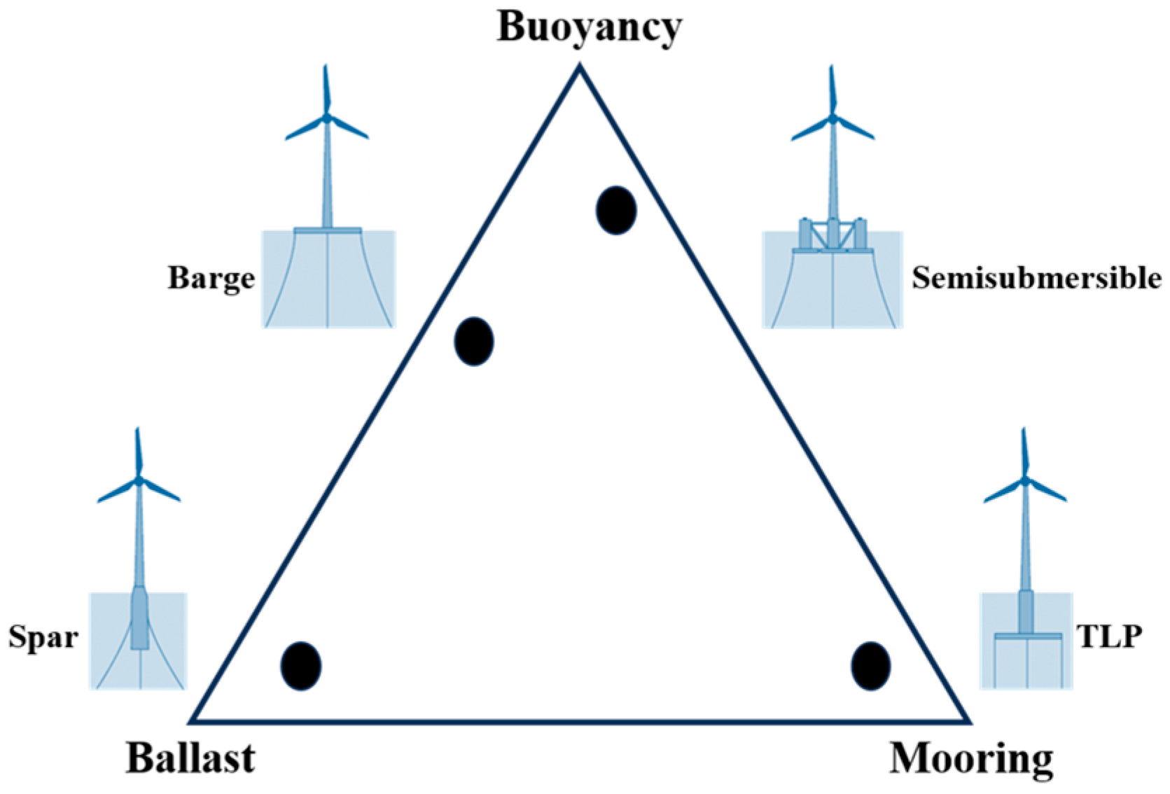
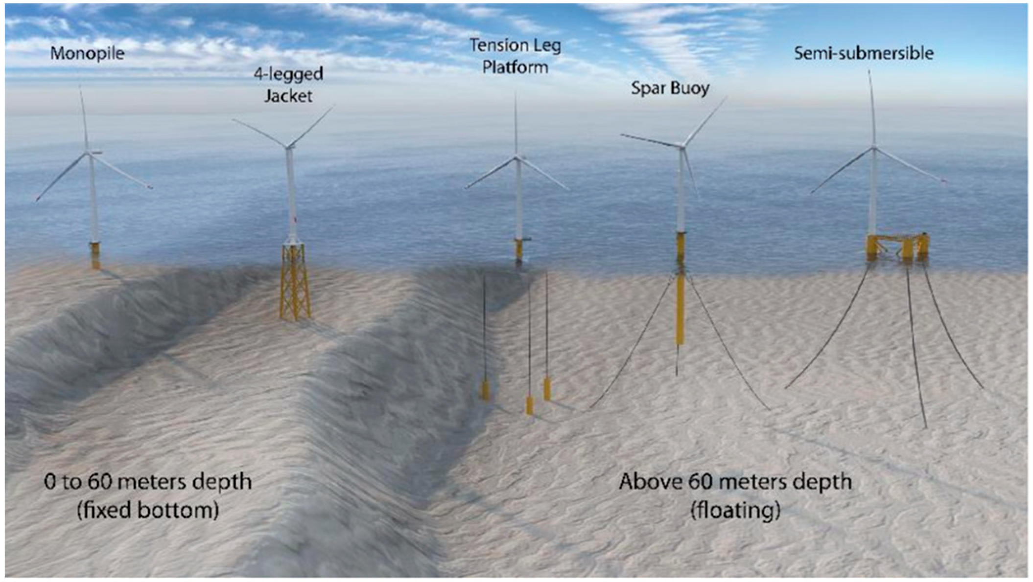
2.3. FOWT Floating Platform Types
2.3.1. Spar Buoy
2.3.2. Tension-Leg Platform (TLP)
2.3.3. Semi-Submersible
2.3.4. Barge-Type
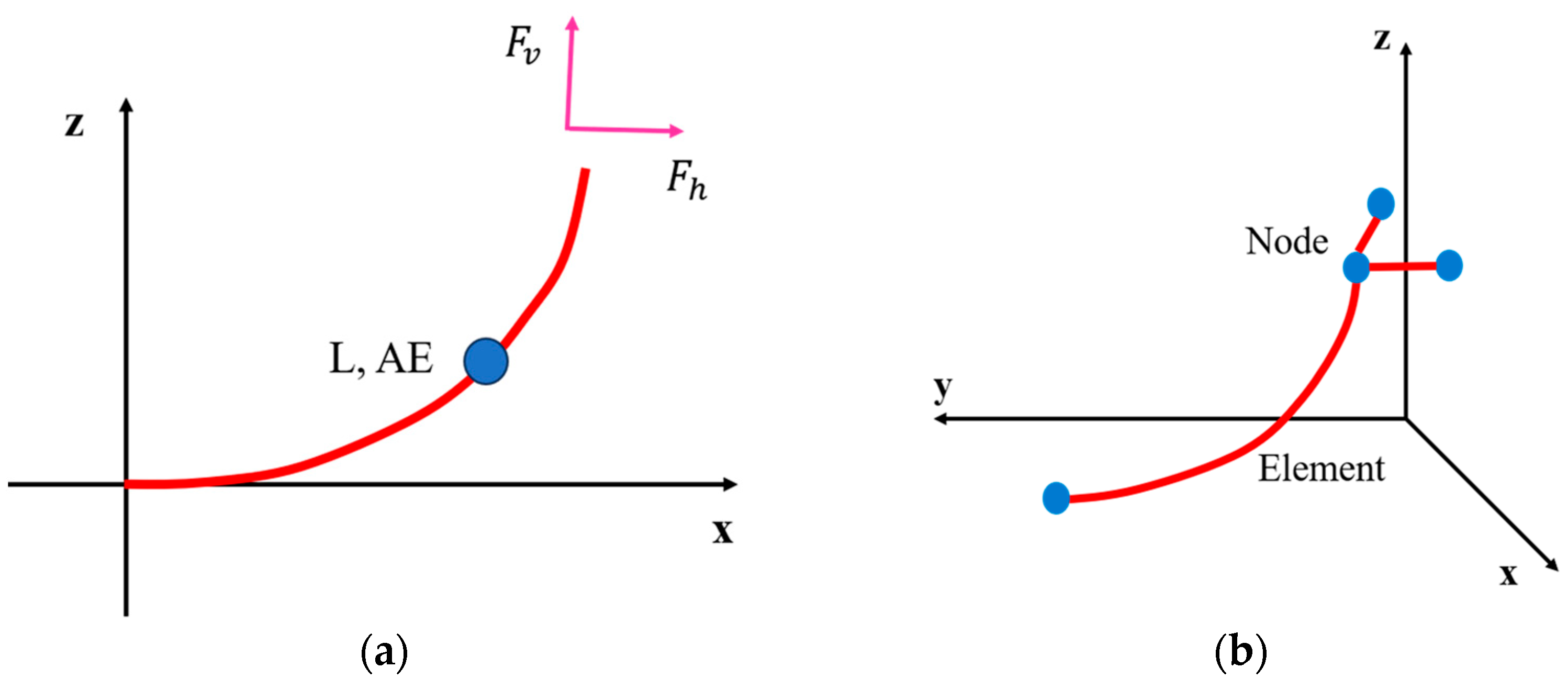
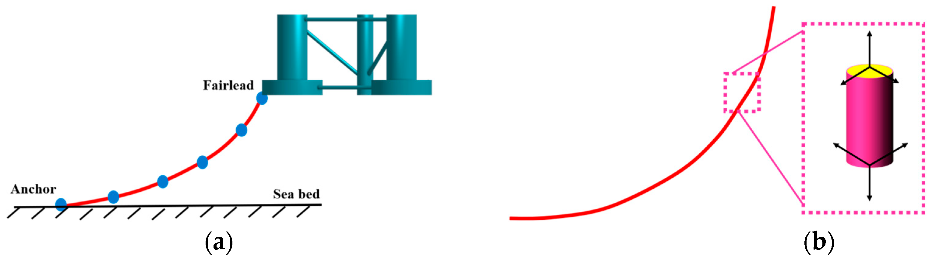
2.4. Mooring Lines
2.4.1. Quasi-Static Approach
2.4.2. Lumped Mass Approach
2.4.3. Finite Element Modeling Approach
2.5. Anchoring System
3. Numerical Modeling
3.1. Background
3.1.1. Analysis Approaches
3.1.2. Fidelity
3.1.3. Software
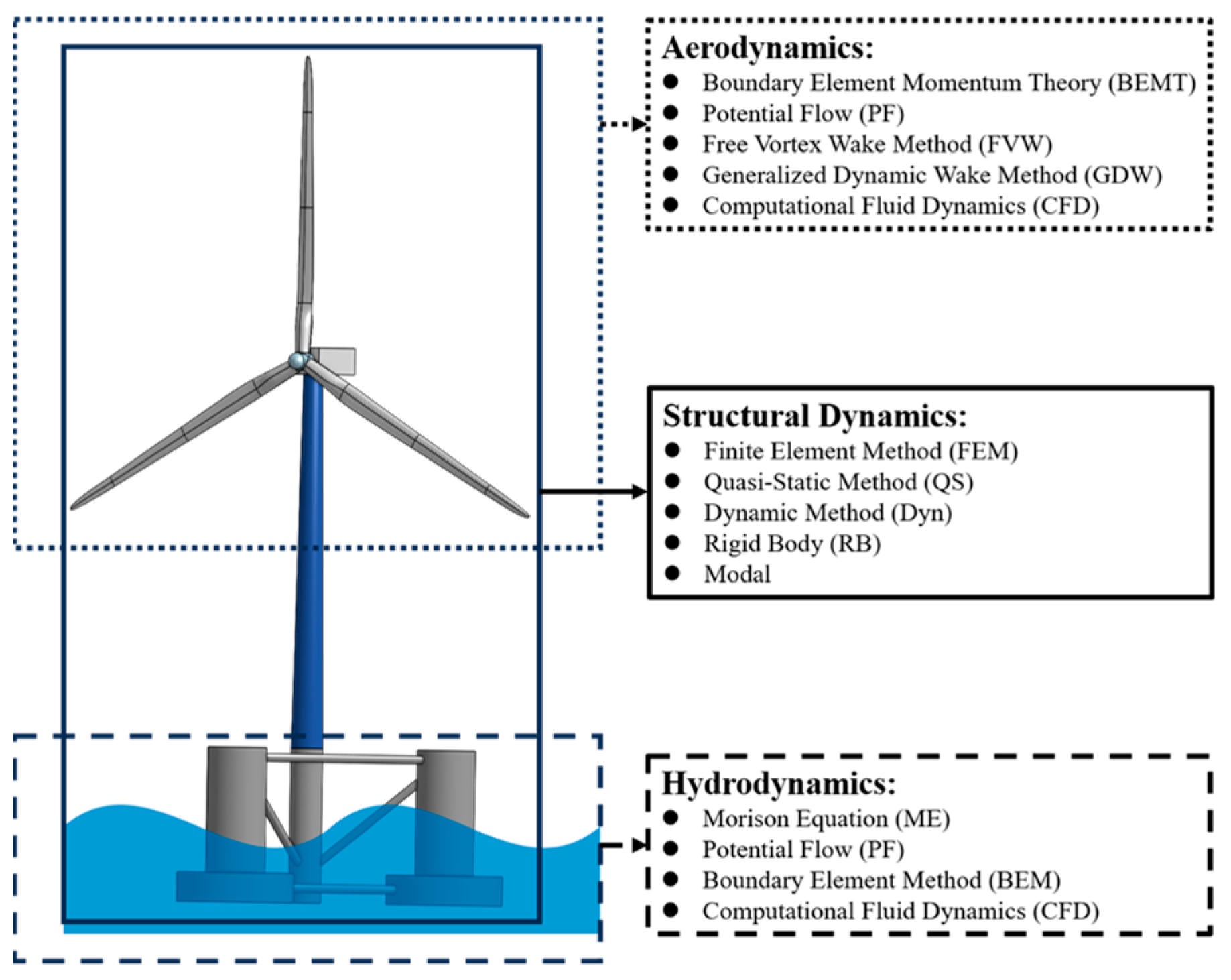
3.2. Hydrodynamics
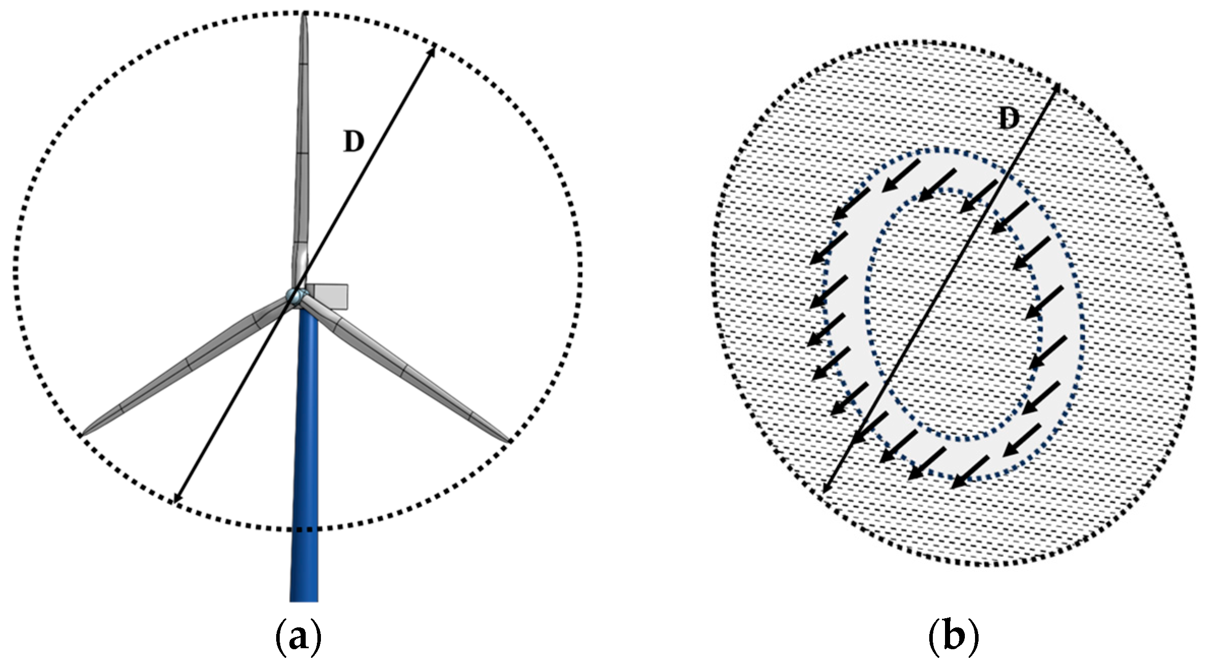
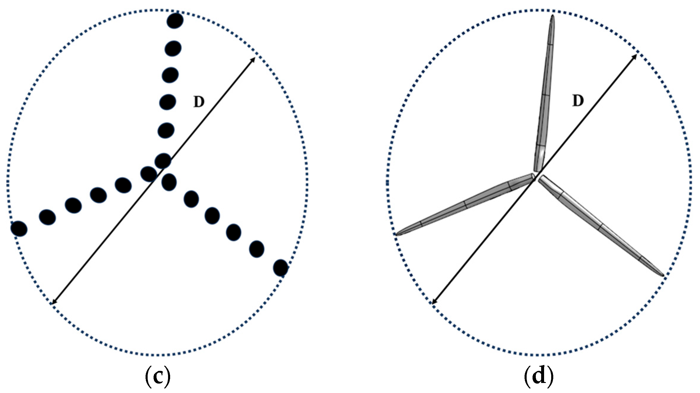
3.3. Aerodynamics
3.4. Structural Dynamics
4. CFD Modelling for FOWT Analysis
4.1. CFD-Based Aerodynamics and Hydrodynamics
4.2. FOWT CFD Analysis
4.2.1. Uncoupled Analysis
4.2.2. Partially Coupled Analysis
4.2.3. Fully Coupled Analysis
5. Challenges and Recommendations
5.1. Modeling Turbulence and Atmospheric Interactions
5.2. Aero-Hydro-Elastic Simulations
5.3. Wake Interactions in Multi-FOWT Systems
5.4. Simulation of Realistic Sea States
6. Conclusions
- Investigate and validate nonlinear EV models for better accuracy in capturing anisotropy in turbulent flows around FOWTs;
- Explore the efficacy of highly refined grid techniques or alternative methods like wall functions to accurately simulate the turbulent boundary layer near FOWT bodies without excessive computational costs;
- Conduct high-fidelity CFD simulations using LES to generate more realistic atmospheric inflow conditions, particularly assessing the effects of large-scale atmospheric turbulence on turbine performance and wake dynamics;
- Assess the impact of different simulation methods for the atmospheric boundary layer on the dynamic responses of FOWTs to ensure an accurate representation of environmental conditions;
- Focus on the integration of aerodynamic, hydrodynamic, and structural dynamics within CFD simulations to address the complex interactions in large-scale FOWTs, especially under severe sea conditions;
- Investigate the physical mechanisms of wake interactions in floating wind farms to optimize the layout and operational strategies, aiming to reduce power deficits and fatigue loads;
- Enhance the simulation models to incorporate realistic, irregular sea states for a better understanding of FOWT behavior under varied wave conditions, which is critical for design and operational planning.
Author Contributions
Funding
Conflicts of Interest
Abbreviations
| AD | Actuator disk |
| AL | Actuator line |
| AS | Actuator surface |
| ABL | Atmospheric boundary layer |
| BEM | Blade element momentum |
| BEM | Boundary element method |
| BEMT | Boundary element momentum theory |
| CFD | Computational fluid dynamics |
| DOF | Degree of freedom |
| DNS | Direct numerical simulation |
| DFBI | Dynamic fluid body interaction |
| Dyn | Dynamic method |
| EV | Eddy viscosity |
| EAL | Elastic actuator line |
| EBM | Equilibrium beam model |
| FEM | Finite element method |
| FVM | Finite volume method |
| FOWTs | Floating offshore wind turbines |
| FVW | Free vortex wake method |
| GDW | Generalized dynamic wake method |
| HPC | High-performance computing |
| HAWTs | Horizontal axis wind turbines |
| IEC | International electrotechnical commission |
| LES | Large eddy simulation |
| LCOE | Levelized costs of energy |
| ME | Morison equation |
| MIMO | Multi-input multi-output |
| NREL | National renewable energy laboratory |
| NSE | Navier–Stokes equations |
| O&M | Operation and maintenance |
| PF | Potential flow |
| QS | Quasi-static method |
| RTHS | Real-time hybrid simulations |
| RANS | Reynolds-averaged Navier–Stokes |
| RST | Reynolds stress turbulence |
| SST | Shear stress transport |
| SPM | Single-point mooring |
| SGS | Subgrid-scale model |
| SDEs | Stochastic differential equations |
| TLP | Tension-leg platform |
| 3D | Three-dimensional |
| TSRs | Tip–speed ratios |
| ULS | Ultimate limit states |
| UALM | Unsteady actuator line method |
| VAWTs | Vertical axis wind turbines |
| VOF | Volume of fluid |
| VLM | Vortex lattice method |
| WECs | Wave energy converters |
References
- Ren, Y.; Shi, W.; Venugopal, V.; Zhang, L.; Li, X. Experimental study of tendon failure analysis for a TLP floating offshore wind turbine. Appl. Energy 2024, 358, 122633. [Google Scholar] [CrossRef]
- Kuriqi, A.; Pinheiro, A.N.; Sordo-Ward, A.; Garrote, L. Flow regime aspects in determining environmental flows and maximising energy production at run-of-river hydropower plants. Appl. Energy 2019, 256, 113980. [Google Scholar] [CrossRef]
- Tian, W.; Wang, Y.; Shi, W.; Michailides, C.; Wan, L.; Chen, M. Numerical study of hydrodynamic responses for a combined concept of semisubmersible wind turbine and different layouts of a wave energy converter. Ocean Eng. 2023, 272, 113824. [Google Scholar] [CrossRef]
- Jiang, Z. Installation of offshore wind turbines: A technical review. Renew. Sustain. Energy Rev. 2021, 139, 110576. [Google Scholar] [CrossRef]
- Wan, L.; Moan, T.; Gao, Z.; Shi, W. A review on the technical development of combined wind and wave energy conversion systems. Energy 2024, 294, 130885. [Google Scholar] [CrossRef]
- Lerch, M.; De-Prada-Gil, M.; Molins, C.; Benveniste, G. Sensitivity analysis on the levelized cost of energy for floating offshore wind farms. Sustain. Energy Technol. 2018, 30, 77–90. [Google Scholar] [CrossRef]
- Wiser, R.; Rand, J.; Seel, J.; Beiter, P.; Baker, E.; Lantz, E.; Gilman, P. Expert elicitation survey predicts 37% to 49% declines in wind energy costs by 2050. Nat. Energy 2021, 6, 555–565. [Google Scholar] [CrossRef]
- Subbulakshmi, A.; Verma, M.; Keerthana, M.; Sasmal, S.; Harikrishna, P.; Kapuria, S. Recent advances in experimental and numerical methods for dynamic analysis of floating offshore wind turbines—An integrated review. Renew. Sustain. Energy Rev. 2022, 164, 112525. [Google Scholar] [CrossRef]
- Bhutta, M.M.A.; Hayat, N.; Farooq, A.U.; Ali, Z.; Jamil, S.R.; Hussain, Z. Vertical axis wind turbine–A review of various configurations and design techniques. Renew. Sustain. Energy Rev. 2012, 16, 1926–1939. [Google Scholar] [CrossRef]
- Möllerström, E.; Gipe, P.; Beurskens, J.; Ottermo, F. A historical review of vertical axis wind turbines rated 100 kW and above. Renew. Sustain. Energy Rev. 2019, 105, 1–13. [Google Scholar] [CrossRef]
- Zhao, Z.; Wang, D.; Wang, T.; Shen, W.; Liu, H.; Chen, M. A review: Approaches for aerodynamic performance improvement of lift-type vertical axis wind turbine. Sustain. Energy Techn. 2022, 49, 101789. [Google Scholar] [CrossRef]
- Matha, D.; Schlipf, M.; Pereira, R.; Jonkman, J. Challenges in simulation of aerodynamics, hydrodynamics, and mooring line dynamics of floating offshore wind turbines. In Proceedings of the ISOPE International Ocean and Polar Engineering Conference, Maui, HI, USA, 19–24 June 2011; p. ISOPE-I. [Google Scholar]
- Röckmann, C.; Lagerveld, S.; Stavenuiter, J. Operation and maintenance costs of offshore wind farms and potential multi-use platforms in the Dutch North Sea. Aquac. Perspect. Multi-Use Sites Open Ocean. Untapped Potential Mar. Resour. Anthr. 2017, 97–113. [Google Scholar] [CrossRef]
- Gueydon, S.; Bayati, I.; De Ridder, E.J. Discussion of solutions for basin model tests of FOWTs in combined waves and wind. Ocean Eng. 2020, 209, 107288. [Google Scholar] [CrossRef]
- Chen, C.; Ma, Y.; Fan, T. Review of model experimental methods focusing on aerodynamic simulation of floating offshore wind turbines. Renew. Sustain. Energy Rev. 2022, 157, 112036. [Google Scholar] [CrossRef]
- Chen, P.; Chen, J.; Hu, Z. Review of experimental-numerical methodologies and challenges for floating offshore wind turbines. J. Mar. Sci. Appl. 2020, 19, 339–361. [Google Scholar] [CrossRef]
- Wang, X.; Cai, C.; Cai, S.; Wang, T.; Wang, Z.; Song, J.; Rong, X. A review of aerodynamic and wake characteristics of floating offshore wind turbines. Renew. Sustain. Energy Rev. 2023, 175, 113144. [Google Scholar] [CrossRef]
- Basbas, H.; Liu, Y.; Laghrouche, S.; Hilairet, M.; Plestan, F. Review on floating offshore wind turbine models for nonlinear control design. Energies 2022, 15, 5477. [Google Scholar] [CrossRef]
- Faraggiana, E.; Giorgi, G.; Sirigu, M.; Ghigo, A.; Bracco, G.; Mattiazzo, G. A review of numerical modelling and optimisation of the floating support structure for offshore wind turbines. J. Ocean Eng. Mar. Energy 2022, 8, 433–456. [Google Scholar] [CrossRef]
- Zhang, H.; Wang, H.; Cai, X.; Xie, J.; Wang, Y.; Zhang, N. Research on the Dynamic Performance of a Novel Floating Offshore Wind Turbine Considering the Fully-Coupled-Effect of the System. J. Mar. Sci. Eng. 2022, 10, 341. [Google Scholar] [CrossRef]
- Mahmuddin, F. Rotor blade performance analysis with blade element momentum theory. Energy Procedia 2017, 105, 1123–1129. [Google Scholar] [CrossRef]
- Yang, H.; Alkhabbaz, A.; Tongphong, W.; Lee, Y. Cross-comparison analysis of environmental load components in extreme conditions for pontoon-connected semi-submersible FOWT using CFD and potential-based tools. Ocean Eng. 2024, 304, 117248. [Google Scholar] [CrossRef]
- Madsen, H.A.; Bak, C.; Døssing, M.; Mikkelsen, R.; Øye, S. Validation and modification of the blade element momentum theory based on comparisons with actuator disc simulations. Wind. Energy Int. J. Prog. Appl. Wind. Power Convers. Technol. 2010, 13, 373–389. [Google Scholar] [CrossRef]
- Tran, T.T.; Kim, D.H. A CFD study of coupled aerodynamic-hydrodynamic loads on a semisubmersible floating offshore wind turbine. Wind Energy 2018, 21, 70–85. [Google Scholar] [CrossRef]
- Ciuriuc, A.; Rapha, J.I.; Guanche, R.; Domínguez-García, J.L. Digital tools for floating offshore wind turbines (FOWT): A state of the art. Energy Rep. 2022, 8, 1207–1228. [Google Scholar] [CrossRef]
- Otter, A.; Murphy, J.; Pakrashi, V.; Robertson, A.; Desmond, C. A review of modelling techniques for floating offshore wind turbines. Wind Energy 2022, 25, 831–857. [Google Scholar] [CrossRef]
- Micallef, D.; Rezaeiha, A. Floating offshore wind turbine aerodynamics: Trends and future challenges. Renew. Sustain. Energy Rev. 2021, 152, 111696. [Google Scholar] [CrossRef]
- Didier, F.; Liu, Y.; Laghrouche, S.; Depernet, D. A Comprehensive Review on Advanced Control Methods for Floating Offshore Wind Turbine Systems above the Rated Wind Speed. Energies 2024, 17, 2257. [Google Scholar] [CrossRef]
- Edwards, E.C.; Holcombe, A.; Brown, S.; Ransley, E.; Hann, M.; Greaves, D. Trends in floating offshore wind platforms: A review of early-stage devices. Renew. Sustain. Energy Rev. 2024, 193, 114271. [Google Scholar] [CrossRef]
- Shi, W.; Fu, J.; Ren, Z.; Jiang, Z.; Wang, T.; Cui, L.; Li, X. Real-time hybrid model tests of floating offshore wind turbines: Status, challenges, and future trends. Appl. Ocean Res. 2023, 141, 103796. [Google Scholar] [CrossRef]
- Ojo, A.; Collu, M.; Coraddu, A. Multidisciplinary design analysis and optimization of floating offshore wind turbine substructures: A review. Ocean Eng. 2022, 266, 112727. [Google Scholar] [CrossRef]
- Xu, S.; Xue, Y.; Zhao, W.; Wan, D. A review of high-fidelity computational fluid dynamics for floating offshore wind turbines. J. Mar. Sci. Eng. 2022, 10, 1357. [Google Scholar] [CrossRef]
- Zhang, W.; Calderon-Sanchez, J.; Duque, D.; Souto-Iglesias, A. Computational Fluid Dynamics (CFD) applications in Floating Offshore Wind Turbine (FOWT) dynamics: A review. Appl. Ocean Res. 2024, 150, 104075. [Google Scholar] [CrossRef]
- Liu, Y. A CFD Study of Fluid-Structure Interaction Problems for Floating Offshore Wind Turbines. Ph.D. Thesis, University of Strathclyde, Glasgow, Scotland, 2018. [Google Scholar]
- Musial, W. Overview of Floating Offshore Wind. In Proceedings of the Webinar Hosted by National Renewable Energy Laboratory, Golden, CO, USA, 26 February 2020. [Google Scholar]
- Wang, L.; Liu, X.; Kolios, A. State of the art in the aeroelasticity of wind turbine blades: Aeroelastic modelling. Renew. Sustain. Energy Rev. 2016, 64, 195–210. [Google Scholar] [CrossRef]
- Cordle, A.; Jonkman, J. State of the Art in FloatingWind Turbine Design Tools. In Proceedings of the Twenty-First International Offshore and Polar Engineering Conference, Maui, HI, USA, 19–24 June 2011; Available online: https://www.onepetro.org/conference-paper/ISOPE-I-11-112 (accessed on 12 June 2024).
- Lemmer, F.; Yu, W.; Luhmann, B.; Schlipf, D.; Cheng, P.W. Multibody modeling for concept-level floating offshore wind turbine design. Multibody Syst. Dyn. 2020, 49, 203–236. [Google Scholar] [CrossRef]
- Nguyen, M.T.; Dang, T.D.; Ahn, K.K. Application of electro-hydraulic actuator system to control continuously variable transmission in wind energy converter. Energies 2019, 12, 2499. [Google Scholar] [CrossRef]
- Yin, X.; Lin, Y.; Li, W.; Gu, H. Hydro-viscous transmission based maximum power extraction control for continuously variable speed wind turbine with enhanced efficiency. Renew. Energy 2016, 87, 646–655. [Google Scholar] [CrossRef]
- Yin, X.; Lin, Y.; Li, W.; Liu, H.; Gu, Y. Output power control for hydro-viscous transmission based continuously variable speed wind turbine. Renew. Energy 2014, 72, 395–405. [Google Scholar] [CrossRef]
- Kumar, D.; Chatterjee, K. A review of conventional and advanced MPPT algorithms for wind energy systems. Renew. Sustain. Energy Rev. 2016, 55, 957–970. [Google Scholar] [CrossRef]
- Chiang, M. A novel pitch control system for a wind turbine driven by a variable-speed pump-controlled hydraulic servo system. Mechatronics 2011, 21, 753–761. [Google Scholar] [CrossRef]
- Yin, X.; Lin, Y.; Li, W. Predictive pitch control of an electro-hydraulic digital pitch system for wind turbines based on the extreme learning machine. Trans. Inst. Meas. Control. 2016, 38, 1392–1400. [Google Scholar] [CrossRef]
- Verma, M.; Nartu, M.K.; Subbulakshmi, A. Optimal TMD design for floating offshore wind turbines considering model uncertainties and physical constraints. Ocean Eng. 2022, 243, 110236. [Google Scholar] [CrossRef]
- He, E.M.; Hu, Y.Q.; Zhang, Y. Optimization design of tuned mass damper for vibration suppression of a barge-type offshore floating wind turbine. Proc. Inst. Mech. Eng. Part M J. Eng. Marit. Environ. 2017, 231, 302–315. [Google Scholar] [CrossRef]
- Brodersen, M.L.; Bjørke, A.S.; Høgsberg, J. Active tuned mass damper for damping of offshore wind turbine vibrations. Wind Energy 2017, 20, 783–796. [Google Scholar] [CrossRef]
- Ghassempour, M.; Failla, G.; Arena, F. Vibration mitigation in offshore wind turbines via tuned mass damper. Eng. Struct. 2019, 183, 610–636. [Google Scholar] [CrossRef]
- Jaksic, V.; Wright, C.S.; Murphy, J.; Afeef, C.; Ali, S.F.; Mandic, D.P.; Pakrashi, V. Dynamic response mitigation of floating wind turbine platforms using tuned liquid column dampers. Philos. Trans. R. Soc. A Math. Phys. Eng. Sci. 2015, 373, 20140079. [Google Scholar] [CrossRef]
- Subbulakshmi, A.; Sundaravadivelu, R. Effects of damping plate position on heave and pitch responses of spar platform with single and double damping plates under regular waves. Ocean Eng. 2021, 224, 108719. [Google Scholar] [CrossRef]
- Subbulakshmi, A.; Sundaravadivelu, R. Heave damping of spar platform for offshore wind turbine with heave plate. Ocean Eng. 2016, 121, 24–36. [Google Scholar] [CrossRef]
- El Beshbichi, O.; Xing, Y.; Chen Ong, M. Linear quadratic regulator optimal control of two-rotor wind turbine mounted on spar-type floating platform. J. Offshore Mech. Arct. Eng. 2023, 145, 022001. [Google Scholar] [CrossRef]
- Li, S.; Han, Y.; Pan, W.; Liu, S.; Hou, M. Variable-gain higher-order sliding mode pitch control of floating offshore wind turbine. J. Mar. Sci. Eng. 2021, 9, 1172. [Google Scholar] [CrossRef]
- Allison, J.T.; Zalkind, D.S.; Herber, D.R. Open-Loop Control Co-Design of Semisubmersible Floating Offshore Wind Turbines Using Linear Parameter-Varying Models. J. Mech. Design 2024, 146, 041704-1. [Google Scholar]
- Jard, T.; Snaiki, R. Real-time repositioning of floating wind turbines using model predictive control for position and power regulation. Wind 2023, 3, 131–150. [Google Scholar] [CrossRef]
- Song, Y.; Jeon, T.; Paek, I.; Dugarjav, B. Design and Validation of Pitch H-Infinity Controller for a Large Wind Turbine. Energies 2022, 15, 8763. [Google Scholar] [CrossRef]
- Brunton, S.L.; Noack, B.R. Closed-loop turbulence control: Progress and challenges. Appl. Mech. Rev. 2015, 67, 050801. [Google Scholar] [CrossRef]
- Society for Underwater Technology. South West–Offshore Floating Wind–Design and Installation. Available online: https://www.sut.org/event/south-west-offshore-floating-wind-design-and-installation/ (accessed on 1 July 2024).
- James, R.; Weng, W.Y.; Spradbery, C.; Jones, J.; Matha, D.; Mitzlaff, A.; Ahilan, R.; Frampton, M.; Lopes, M. Floating Wind Joint Industry Project—Phase I Summary Report. Carbon Trust Technol. Rep. 2018, 19, 2–20. [Google Scholar]
- Kim, D.; Bae, Y.H.; Park, S. Design strategy for resonance avoidance to improve the performance of tension leg platform-type floating offshore wind turbines. Ocean Eng. 2024, 306, 118080. [Google Scholar] [CrossRef]
- Zhai, Y.; Zhao, H.; Li, X.; Shi, W. Design and Dynamic Analysis of a Novel Large-Scale Barge-Type Floating Offshore Wind Turbine with Aquaculture Cage. J. Mar. Sci. Eng. 2022, 10, 1926. [Google Scholar] [CrossRef]
- Thiagarajan, K.P.; Dagher, H.J. A review of floating platform concepts for offshore wind energy generation. J. Offshore Mech. Arct. Eng. 2014, 136, 020903. [Google Scholar] [CrossRef]
- Liu, Y.; Yoshida, S.; Yamamoto, H.; Toyofuku, A.; He, G.; Yang, S. Response characteristics of the DeepCwind floating wind turbine moored by a single-point mooring system. Appl. Sci. 2018, 8, 2306. [Google Scholar] [CrossRef]
- Nihei, Y.; Matsuda, Y.; Kitamura, S.; Takaiwa, K.; Kanda, N. Research and development about the mechanisms of a single point mooring system for offshore wind turbines. Ocean Eng. 2018, 147, 431–446. [Google Scholar] [CrossRef]
- Zhong, W.; Zhao, W.; Wan, D.; Zhao, Y. Comparison study on mooring line models for hydrodynamic performances of floating offshore wind turbines. Ocean Eng. 2024, 296, 117083. [Google Scholar] [CrossRef]
- Masciola, M.; Jonkman, J.; Robertson, A. Implementation of a Multisegmented, Quasi-Static Cable Model. In Proceedings of the 23rd International Offshore and Polar Engineering Conference, Anchorage, AK, USA, 30 June–5 July 2013. [Google Scholar]
- Cevasco, D.; Collu, M.; Rizzo, C.M.; Hall, M. On mooring line tension and fatigue prediction for offshore vertical axis wind turbines: A comparison of lumped mass and quasi-static approaches. Wind Eng. 2018, 42, 97–107. [Google Scholar] [CrossRef]
- Ishihara, T.; Phuc, P.V.; Sukegawa, H.; Shimada, K. A study on the dynamic response of a semi-submersible floating offshore wind turbine system Part 1: A water tank test. In Proceedings of the 12th International Conference on Wind Engineering: ICWE 12, Cairns, Australia, 1–6 July 2007; p. 4. [Google Scholar]
- Hall, M.; Buckham, B.; Crawford, C. Evaluating the importance of mooring line model fidelity in floating offshore wind turbine simulations. Wind Energy 2014, 17, 1835–1853. [Google Scholar] [CrossRef]
- Azcona, J.; Nygaard, T.A.; Munduate, X.; Merino, D. Development of a Code for Dynamic Simulation of Mooring Lines in Contact with Seabed; EWEA Offshore: Amsterdam, The Netherlands, 2011. [Google Scholar]
- Palm, J.; Eskilsson, C.; Bergdahl, L. An hp-adaptive discontinuous Galerkin method for modelling snap loads in mooring cables. Ocean Eng. 2017, 144, 266–276. [Google Scholar] [CrossRef]
- Palm, J.; Eskilsson, C.; Paredes, G.M.; Bergdahl, L. Coupled mooring analysis for floating wave energy converters using CFD: Formulation and validation. Int. J. Mar. Energy 2016, 16, 83–99. [Google Scholar] [CrossRef]
- Müller, K.; Lemmer, F.; Borisade, F.; Kretschmer, M.; Gruber, J.; Hagemann, L. State-of-the-art FOWT design practice and guidelines. Lifes50+ Deliv. 2016, 7, 2016. [Google Scholar]
- Larsen, T.J.; Hansen, A.M. How 2 HAWC2, the User’s Manual; Risø National Laboratory: Roskilde, Denmark, 2007. [Google Scholar]
- Jonkman, J.M. FAST User’s Guide; National Renewable Energy Laboratory: Golden, CO, USA, 2005; Volume 365. [Google Scholar]
- DNV GL. Coupled Analysis of Floating Wind Turbines; DNVGL-RP-0286; DNV GL: Høvik, Norway, 2019. [Google Scholar]
- Wood, D.H.; Golmirzaee, N. A revision of blade element/momentum theory for wind turbines in their high-thrust region. Front. Energy Res. 2023, 11, 1256308. [Google Scholar] [CrossRef]
- Faltinsen, O. Sea Loads on Ships and Offshore Structures; Cambridge University Press: Cambridge, UK, 1993; Volume 1. [Google Scholar]
- Xu, B.F.; Wang, T.G.; Yuan, Y.; Zhao, Z.Z.; Liu, H.M. A simplified free vortex wake model of wind turbines for axial steady conditions. Appl. Sci. 2018, 8, 866. [Google Scholar] [CrossRef]
- Jiang, Z.; Xing, Y.; Guo, Y.; Moan, T.; Gao, Z. Long-term contact fatigue analysis of a planetary bearing in a land-based wind turbine drivetrain. Wind Energy 2015, 18, 591–611. [Google Scholar] [CrossRef]
- Zienkiewicz, O.C.; Taylor, R.L.; Zhu, J.Z. The Finite Element Method: Its Basis and Fundamental; Elsevier: Amsterdam, The Netherlands, 2005. [Google Scholar]
- Li, C.B.; Chen, M.; Choung, J. The quasi-static response of moored floating structures based on minimization of mechanical energy. J. Mar. Sci. Eng. 2021, 9, 960. [Google Scholar] [CrossRef]
- Dong, Y.; Chen, Y.; Liu, H.; Zhou, S.; Ni, Y.; Cai, C.; Zhou, T.; Li, Q. Review of Study on the Coupled Dynamic Performance of Floating Offshore Wind Turbines. Energies 2022, 15, 3970. [Google Scholar] [CrossRef]
- Morison, J.R.; Johnson, J.W.; Schaaf, S.A. The force exerted by surface waves on piles. J. Pet. Technol. 1950, 2, 149–154. [Google Scholar] [CrossRef]
- Brebbia, C.A. The Boundary Element Method for Engineers; Pentech Press: Xi’an, China, 1978. [Google Scholar]
- Tu, J.; Yeoh, G.H.; Liu, C. Computational Fluid Dynamics: A Practical Approach; Butterworth-Heinemann: Oxford, UK, 2018. [Google Scholar]
- Orcina Ltd. OrcaFlex, Version 10.3d; Orcina Ltd.: Ulverston, UK, 2019.
- Flexcom Technical Manual; Wood Group Kenny: Galway, Ireland, 2014.
- Systèmes, D. Simpack MBS Software|Dassault Systèmes. Available online: https://www.3ds.com/products/simulia/simpack (accessed on 1 July 2024).
- Marine Operations and Mooring Analysis Software—Sima. Available online: https://www.dnv.com/services/marine-operations-and-mooring-analysis-software-sima-2324/ (accessed on 1 July 2024).
- Jasak, H. OpenFOAM: Open source CFD in research and industry. Int. J. Nav. Archit. Ocean Eng. 2009, 1, 89–94. [Google Scholar]
- Ansys. Ansys|Engineering Simulation Software. Available online: https://www.ansys.com (accessed on 1 July 2024).
- Hibbitt, Karlsson & Sorensen, Inc. ABAQUS/Standard User’s Manual; ABAQUS; Hibbitt, Karlsson & Sorensen, Inc.: Pawtucket, RI, USA, 2010. [Google Scholar]
- Simcenter Star-CCM+ Documentation, Version 2020.2. 2020. Available online: https://www.aerofem.com/assets/files/Simcenter-STAR-CCM-2020.2-New-FeaturesFact-Sheet.pdf (accessed on 1 July 2024).
- Shen, C.; Chen, N. A SWENSE-based wave-induced loading simulation for a semi-submersible FOWT platform. Ocean Eng. 2024, 311, 118950. [Google Scholar] [CrossRef]
- Archambeau, F.; Méchitoua, N.; Sakiz, M. Code Saturne: A finite volume code for the computation of turbulent incompressible flows-Industrial applications. Int. J. Finite Vol. 2004, 1, 1–62. [Google Scholar]
- Bihs, H.; Kamath, A.; Alagan Chella, M.; Aggarwal, A.; Arntsen, Ø.A. A new level set numerical wave tank with improved density interpolation for complex wave hydrodynamics. Comput. Fluids 2016, 140, 191–208. [Google Scholar] [CrossRef]
- Benitz, M.A.; Lackner, M.A.; Schmidt, D.P. Hydrodynamics of offshore structures with specific focus on wind energy applications. Renew. Sustain. Energy Rev. 2015, 44, 692–716. [Google Scholar] [CrossRef]
- Edition, F.; Journée, J.; Massie, W.W. Offshore Hydromechanics; Delft Univ. Technology: Delft, The Netherlands, 2001. [Google Scholar]
- Uzunoglu, E.; Soares, C.G. On the model uncertainty of wave induced platform motions and mooring loads of a semisubmersible based wind turbine. Ocean Eng. 2018, 148, 277–285. [Google Scholar] [CrossRef]
- Leble, V.; Barakos, G. Demonstration of a coupled floating offshore wind turbine analysis with high-fidelity methods. J. Fluid. Struct. 2016, 62, 272–293. [Google Scholar] [CrossRef]
- Siddiqui, M.A.; Hanssen, F.W.; Greco, M.; Anda, E. Comparing the Utility of Coupled Aero-Hydrodynamic Analysis Using a CFD Solver versus a Potential Flow Solver for Floating Offshore Wind Turbines. Energies 2023, 16, 7833. [Google Scholar] [CrossRef]
- Zhou, Y.; Xiao, Q.; Liu, Y.; Incecik, A.; Peyrard, C.; Li, S.; Pan, G. Numerical modelling of dynamic responses of a floating offshore wind turbine subject to focused waves. Energies 2019, 12, 3482. [Google Scholar] [CrossRef]
- Liu, Y.; Xiao, Q.; Incecik, A.; Wan, D. Investigation of the effects of platform motion on the aerodynamics of a floating offshore wind turbine. J. Hydrodyn. 2016, 28, 95–101. [Google Scholar] [CrossRef]
- Lee, H.; Lee, D. Effects of platform motions on aerodynamic performance and unsteady wake evolution of a floating offshore wind turbine. Renew. Energy 2019, 143, 9–23. [Google Scholar] [CrossRef]
- Schulz, C.W.; Netzband, S.; Özinan, U.; Cheng, P.W.; Abdel-Maksoud, M. Wind turbine rotors in surge motion: New insights into unsteady aerodynamics of floating offshore wind turbines (FOWTs) from experiments and simulations. Wind Energy Sci. 2024, 9, 665–695. [Google Scholar] [CrossRef]
- Schulz, C.W.; Netzband, S.; Özinan, U.; Cheng, P.W.; Abdel-Maksoud, M. Wind turbine rotors in surge motion: New insights into unsteady aerodynamics of FOWT from experiments and simulations. Wind. Energy Sci. Discuss. 2023, 2023, 1–47. [Google Scholar]
- Henriksen, L.C.; Hansen, M.H.; Poulsen, N.K. A simplified dynamic inflow model and its effect on the performance of free mean wind speed estimation. Wind Energy 2013, 16, 1213–1224. [Google Scholar] [CrossRef]
- Ferreira, C.; Yu, W.; Sala, A.; Viré, A. Dynamic inflow model for a floating horizontal axis wind turbine in surge motion. Wind Energy Sci. 2022, 7, 469–485. [Google Scholar] [CrossRef]
- Wu, C.H.K.; Nguyen, V.T. Aerodynamic simulations of offshore floating wind turbine in platform-induced pitching motion. Wind Energy 2017, 20, 835–858. [Google Scholar] [CrossRef]
- Liu, Y.; Xiao, Q.; Incecik, A.; Peyrard, C. Aeroelastic analysis of a floating offshore wind turbine in platform-induced surge motion using a fully coupled CFD-MBD method. Wind Energy 2019, 22, 1–20. [Google Scholar] [CrossRef]
- Ramos García, N.; Kontos, S.; Pegalajar Jurado, A.; González Horcas, S.; Bredmose, H. Investigation of the floating IEA Wind 15 MW RWT using vortex methods Part I: Flow regimes and wake recovery. Wind Energy 2022, 25, 468–504. [Google Scholar] [CrossRef]
- Sebastian, T.; Lackner, M.A. Development of a free vortex wake method code for offshore floating wind turbines. Renew. Energy 2012, 46, 269–275. [Google Scholar] [CrossRef]
- Shaler, K.; Branlard, E.; Platt, A.; Jonkman, J. Preliminary introduction of a free vortex wake method into OpenFAST. J. Phys. Conf. Ser. 2020, 1452, 012064. [Google Scholar] [CrossRef]
- Sebastian, T.; Lackner, M. Analysis of the induction and wake evolution of an offshore floating wind turbine. Energies 2012, 5, 968–1000. [Google Scholar] [CrossRef]
- Kadum, H.; Rockel, S.; Viggiano, B.; Dib, T.; Hölling, M.; Chevillard, L.; Cal, R.B. Assessing intermittency characteristics via cumulant analysis of floating wind turbines wakes. J. Renew. Sustain. Energy 2021, 13, 013302. [Google Scholar] [CrossRef]
- Tran, T.; Kim, D. The platform pitching motion of floating offshore wind turbine: A preliminary unsteady aerodynamic analysis. J. Wind Eng. Ind. Aerod. 2015, 142, 65–81. [Google Scholar] [CrossRef]
- Rega, G. Nonlinear vibrations of suspended cables—Part II: Deterministic phenomena. Appl. Mech. Rev. 2004, 57, 479–514. [Google Scholar] [CrossRef]
- Larsen, J.W.; Nielsen, S.R. Non-linear dynamics of wind turbine wings. Int. J. Nonlin. Mech. 2006, 41, 629–643. [Google Scholar] [CrossRef]
- Larsen, J.W.; Nielsen, S.R. Nonlinear parametric instability of wind turbine wings. J. Sound Vib. 2007, 299, 64–82. [Google Scholar] [CrossRef]
- Jaksic, V.; O’Shea, R.; Cahill, P.; Murphy, J.; Mandic, D.P.; Pakrashi, V. Dynamic response signatures of a scaled model platform for floating wind turbines in an ocean wave basin. Philos. Trans. R. Soc. A Math. Phys. Eng. Sci. 2015, 373, 20140078. [Google Scholar] [CrossRef]
- Campos, A.; Molins, C.; Trubat, P.; Alarcón, D. A 3D FEM model for floating wind turbines support structures. Energy Procedia 2017, 137, 177–185. [Google Scholar] [CrossRef]
- Sun, C. Mitigation of offshore wind turbine responses under wind and wave loading: Considering soil effects and damage. Struct. Control. Health Monit. 2018, 25, e2117. [Google Scholar] [CrossRef]
- Tagliafierro, B.; Karimirad, M.; Altomare, C.; Göteman, M.; Martínez-Estévez, I.; Capasso, S.; Domínguez, J.M.; Viccione, G.; Gómez-Gesteira, M.; Crespo, A.J. Numerical validations and investigation of a semi-submersible floating offshore wind turbine platform interacting with ocean waves using an SPH framework. Appl. Ocean Res. 2023, 141, 103757. [Google Scholar] [CrossRef]
- Meier, C.; Popp, A.; Wall, W.A. Geometrically exact finite element formulations for slender beams: Kirchhoff–Love theory versus Simo–Reissner theory. Arch. Comput. Method E 2019, 26, 163–243. [Google Scholar] [CrossRef]
- Bathe, K.J. Finite Element Procedures; Prentice Hall: Upper Saddle River, NJ, USA, 1996. [Google Scholar]
- Farhat, C.; Avery, P.; Chapman, T.; Cortial, J. Dimensional reduction of nonlinear finite element dynamic models with finite rotations and energy-based mesh sampling and weighting for computational efficiency. Int. J. Numer. Meth. Eng. 2014, 98, 625–662. [Google Scholar] [CrossRef]
- Oh, S.; Ishii, K.; Iijima, K.; Suzuki, H. Implementation of potential flow hydrodynamics to time-domain analysis of flexible platforms of floating offshore wind turbines. J. Phys. Conf. Ser. 2019, 1356, 012041. [Google Scholar] [CrossRef]
- Cheng, A.H.; Cheng, D.T. Heritage and early history of the boundary element method. Eng. Anal. Bound Elem. 2005, 29, 268–302. [Google Scholar] [CrossRef]
- Atcheson, M.; Garrad, A.; Cradden, L.; Henderson, A.; Matha, D.; Nichols, J.; Roddier, D.; Sandberg, J. Floating Offshore Wind Energy; Springer: Berlin/Heidelberg, Germany, 2016; Volume 10, pp. 978–983. [Google Scholar]
- Suzuki, H.; Shiohara, H.; Schnepf, A.; Houtani, H.; Carmo, L.H.; Hirabayashi, S.; Haneda, K.; Chujo, T.; Nihei, Y.; Malta, E.B. Wave and wind responses of a very-light fowt with guy-wired-supported tower: Numerical and experimental studies. J. Mar. Sci. Eng. 2020, 8, 841. [Google Scholar] [CrossRef]
- Freyer, K. Wire Ropes Under Bending and Tensile Stresses. In Wire Ropes; Springer: Berlin/Heidelberg, Germany, 2007. [Google Scholar]
- Cardiff, P.; Demirdžić, I. Thirty years of the finite volume method for solid mechanics. Arch Comput. Method E 2021, 28, 3721–3780. [Google Scholar] [CrossRef]
- Yang, S.; Ringsberg, J.W.; Johnson, E.; Hu, Z. Biofouling on mooring lines and power cables used in wave energy converter systems—Analysis of fatigue life and energy performance. Appl. Ocean Res. 2017, 65, 166–177. [Google Scholar] [CrossRef]
- Qiao, D.; Haider, R.; Yan, J.; Ning, D.; Li, B. Review of wave energy converter and design of mooring system. Sustainability 2020, 12, 8251. [Google Scholar] [CrossRef]
- Azcona, J.; Palacio, D.; Munduate, X.; Gonzalez, L.; Nygaard, T.A. Impact of mooring lines dynamics on the fatigue and ultimate loads of three offshore floating wind turbines computed with IEC 61400-3 guideline. Wind Energy 2017, 20, 797–813. [Google Scholar] [CrossRef]
- Chen, L.; Basu, B.; Nielsen, S.R. Nonlinear periodic response analysis of mooring cables using harmonic balance method. J. Sound Vib. 2019, 438, 402–418. [Google Scholar] [CrossRef]
- Ishihara, T.; Zhang, S. Prediction of dynamic response of semi-submersible floating offshore wind turbine using augmented Morison’s equation with frequency dependent hydrodynamic coefficients. Renew. Energy 2019, 131, 1186–1207. [Google Scholar] [CrossRef]
- Zhou, Y.; Xiao, Q.; Liu, Y.; Incecik, A.; Peyrard, C.; Wan, D.; Pan, G.; Li, S. Exploring inflow wind condition on floating offshore wind turbine aerodynamic characterisation and platform motion prediction using blade resolved CFD simulation. Renew. Energy 2022, 182, 1060–1079. [Google Scholar] [CrossRef]
- Cao, J.; Qin, Z.; Ju, Y.; Chen, Y.; Shen, W.Z.; Shen, X.; Ke, S. Study of air compressibility effects on the aerodynamic performance of the IEA-15 MW offshore wind turbine. Energy Convers. Manag. 2023, 282, 116883. [Google Scholar] [CrossRef]
- Fang, Y.; Duan, L.; Han, Z.; Zhao, Y.; Yang, H. Numerical analysis of aerodynamic performance of a floating offshore wind turbine under pitch motion. Energy 2020, 192, 116621. [Google Scholar] [CrossRef]
- Sanderse, B.; Van der Pijl, S.P.; Koren, B. Review of computational fluid dynamics for wind turbine wake aerodynamics. Wind Energy 2011, 14, 799–819. [Google Scholar] [CrossRef]
- Thé, J.; Yu, H. A critical review on the simulations of wind turbine aerodynamics focusing on hybrid RANS-LES methods. Energy 2017, 138, 257–289. [Google Scholar] [CrossRef]
- Abkar, M. Impact of subgrid-scale modeling in actuator-line based large-eddy simulation of vertical-axis wind turbine wakes. Atmosphere 2018, 9, 257. [Google Scholar] [CrossRef]
- Leonard, A. Energy cascade in large-eddy simulations of turbulent fluid flow. Adv. Geophys. 1974, 18, 237–248. [Google Scholar]
- Wu, C.; Wang, Q.; Yuan, R.; Luo, K.; Fan, J. Large eddy simulation of the layout effects on wind farm performance coupling with wind turbine control strategies. J. Energy Resour. Technol. 2022, 144, 051304. [Google Scholar] [CrossRef]
- Porté-Agel, F.; Meneveau, C.; Parlange, M.B. A scale-dependent dynamic model for large-eddy simulation: Application to a neutral atmospheric boundary layer. J. Fluid. Mech. 2000, 415, 261–284. [Google Scholar] [CrossRef]
- Abdulqadir, S.A.; Iacovides, H.; Nasser, A. The physical modelling and aerodynamics of turbulent flows around horizontal axis wind turbines. Energy 2017, 119, 767–799. [Google Scholar] [CrossRef]
- Abkar, M.; Moin, P. Large-eddy simulation of thermally stratified atmospheric boundary-layer flow using a minimum dissipation model. Bound-Lay Meteorol. 2017, 165, 405–419. [Google Scholar] [CrossRef]
- Sørensen, J.N.; Mikkelsen, R.F.; Henningson, D.S.; Ivanell, S.; Sarmast, S.; Andersen, S.J. Simulation of wind turbine wakes using the actuator line technique. Philos. Trans. R. Soc. A Math. Phys. Eng. Sci. 2015, 373, 20140071. [Google Scholar] [CrossRef]
- Amiri, M.M.; Shadman, M.; Estefen, S.F. A review of physical and numerical modeling techniques for horizontal-axis wind turbine wakes. Renew. Sustain. Energy Rev. 2024, 193, 114279. [Google Scholar] [CrossRef]
- Whale, J.; Anderson, C.G.; Bareiss, R.; Wagner, S. An experimental and numerical study of the vortex structure in the wake of a wind turbine. J. Wind Eng. Ind. Aerod. 2000, 84, 1–21. [Google Scholar] [CrossRef]
- Ivanell, S.; Sørensen, J.N.; Mikkelsen, R.; Henningson, D. Analysis of numerically generated wake structures. Wind Energy 2009, 12, 63–80. [Google Scholar] [CrossRef]
- Mejia, O.D.L.; Quiñones, J.J.; Laín, S. RANS and hybrid RANS-LES simulations of an H-type Darrieus vertical axis water turbine. Energies 2018, 11, 2348. [Google Scholar] [CrossRef]
- Lei, H.; Zhou, D.; Bao, Y.; Chen, C.; Ma, N.; Han, Z. Numerical simulations of the unsteady aerodynamics of a floating vertical axis wind turbine in surge motion. Energy 2017, 127, 1–17. [Google Scholar] [CrossRef]
- Heinz, S. A review of hybrid RANS-LES methods for turbulent flows: Concepts and applications. Prog. Aerosp. Sci. 2020, 114, 100597. [Google Scholar] [CrossRef]
- Syawitri, T.P.; Yao, Y.F.; Chandra, B.; Yao, J. Comparison study of URANS and hybrid RANS-LES models on predicting vertical axis wind turbine performance at low, medium and high tip speed ratio ranges. Renew. Energy 2021, 168, 247–269. [Google Scholar] [CrossRef]
- Xu, S.; Yang, X.; Zhao, W.; Wan, D. Numerical analysis of aero-hydrodynamic wake flows of a floating offshore wind turbine subjected to atmospheric turbulence inflows. Ocean Eng. 2024, 300, 117498. [Google Scholar] [CrossRef]
- Bai, C.; Wang, W. Review of computational and experimental approaches to analysis of aerodynamic performance in horizontal-axis wind turbines (HAWTs). Renew. Sustain. Energy Rev. 2016, 63, 506–519. [Google Scholar] [CrossRef]
- Tran, T.T.; Kim, D. The coupled dynamic response computation for a semi-submersible platform of floating offshore wind turbine. J. Wind Eng. Ind. Aerod. 2015, 147, 104–119. [Google Scholar] [CrossRef]
- Burmester, S.; Vaz, G.; Gueydon, S.; El Moctar, O. Investigation of a semi-submersible floating wind turbine in surge decay using CFD. Ship Technol. Res. 2020, 67, 2–14. [Google Scholar] [CrossRef]
- Zhao, W.; Wan, D. Numerical study of interactions between phase II of OC4 wind turbine and its semi-submersible floating support system. J. Ocean Wind Energy 2015, 2, 45–53. [Google Scholar]
- Bruinsma, N.; Paulsen, B.T.; Jacobsen, N.G. Validation and application of a fully nonlinear numerical wave tank for simulating floating offshore wind turbines. Ocean Eng. 2018, 147, 647–658. [Google Scholar] [CrossRef]
- Boussinesq, J. Theorie de l’ecoulement tourbillant. Mem. Acad. Sci. 1877, 23, 46. [Google Scholar]
- Ammara, I.; Leclerc, C.; Masson, C. A viscous three-dimensional differential/actuator-disk method for the aerodynamic analysis of wind farms. J. Sol. Energy 2002, 124, 345–356. [Google Scholar] [CrossRef]
- Eça, L.; Hoekstra, M. Near-wall profiles of mean flow and turbulence quantities predicted by eddy-viscosity turbulence models. Int. J. Numer. Methods Fluids 2010, 63, 953–988. [Google Scholar] [CrossRef]
- Swanson, R.C.; Rossow, C. An efficient solver for the RANS equations and a one-equation turbulence model. Comput. Fluids 2011, 42, 13–25. [Google Scholar] [CrossRef]
- Heinz, S.; Mokhtarpoor, R.; Stoellinger, M. Theory-based Reynolds-averaged Navier–Stokes equations with large eddy simulation capability for separated turbulent flow simulations. Phys. Fluids 2020, 32, 065102. [Google Scholar] [CrossRef]
- Burmester, S.; Vaz, G.; El Moctar, O. Towards credible CFD simulations for floating offshore wind turbines. Ocean Eng. 2020, 209, 107237. [Google Scholar] [CrossRef]
- Li, H.; Bachynski-Polić, E.E. Analysis of difference-frequency wave loads and quadratic transfer functions on a restrained semi-submersible floating wind turbine. Ocean Eng. 2021, 232, 109165. [Google Scholar] [CrossRef]
- Pinto, M.L.; Franzini, G.R.; Simos, A.N. A CFD analysis of NREL’s 5MW wind turbine in full and model scales. J. Ocean Eng. Mar. Energy 2020, 6, 211–220. [Google Scholar] [CrossRef]
- Naderi, S.; Parvanehmasiha, S.; Torabi, F. Modeling of horizontal axis wind turbine wakes in Horns Rev offshore wind farm using an improved actuator disc model coupled with computational fluid dynamic. Energy Convers. Manag. 2018, 171, 953–968. [Google Scholar] [CrossRef]
- Rezaeiha, A.; Micallef, D. Wake interactions of two tandem floating offshore wind turbines: CFD analysis using actuator disc model. Renew. Energy 2021, 179, 859–876. [Google Scholar] [CrossRef]
- O’Brien, J.M.; Young, T.M.; Early, J.M.; Griffin, P.C. An assessment of commercial CFD turbulence models for near wake HAWT modelling. J. Wind Eng. Ind. Aerod. 2018, 176, 32–53. [Google Scholar] [CrossRef]
- Vogel, C.R.; Willden, R.H. Investigation of wind turbine wake superposition models using Reynolds-averaged Navier-Stokes simulations. Wind Energy 2020, 23, 593–607. [Google Scholar] [CrossRef]
- Amiri, M.M.; Shadman, M.; Estefen, S.F. URANS simulations of a horizontal axis wind turbine under stall condition using Reynolds stress turbulence models. Energy 2020, 213, 118766. [Google Scholar] [CrossRef]
- Antonini, E.G.; Romero, D.A.; Amon, C.H. Improving CFD wind farm simulations incorporating wind direction uncertainty. Renew. Energy 2019, 133, 1011–1023. [Google Scholar] [CrossRef]
- Schumann, U. Realizability of Reynolds-stress turbulence models. Phys. Fluids 1977, 20, 721–725. [Google Scholar] [CrossRef]
- Cabezon, D.; Migoya, E.; Crespo, A. Comparison of turbulence models for the computational fluid dynamics simulation of wind turbine wakes in the atmospheric boundary layer. Wind Energy 2011, 14, 909–921. [Google Scholar] [CrossRef]
- Gomez-Elvira, R.; Crespo, A.; Migoya, E.; Manuel, F.; Hernández, J. Anisotropy of turbulence in wind turbine wakes. J. Wind Eng. Ind. Aerod. 2005, 93, 797–814. [Google Scholar] [CrossRef]
- Yang, X.; Sotiropoulos, F. On the predictive capabilities of LES-actuator disk model in simulating turbulence past wind turbines and farms. In Proceedings of the 2013 American Control Conference, Washington, DC, USA, 17–19 June 2013; pp. 2878–2883. [Google Scholar]
- Corniglion, R.; Harris, J.; Peyrard, C.; Capaldo, M. In Comparison of the free vortex wake and actuator line methods to study the loads of a wind turbine in imposed surge motion. J. Phys. Conf. Ser. 2020, 1618, 052045. [Google Scholar] [CrossRef]
- Sanvito, A.G.; Persico, G.; Schito, P.; Dossena, V.; Zasso, A. In Comparative assessment of actuator-Line modeling of FOWT rotor aerodynamics to wind tunnel experiments. J. Phys. Conf. Ser. 2023, 2626, 012063. [Google Scholar] [CrossRef]
- Arabgolarcheh, A.; Micallef, D.; Rezaeiha, A.; Benini, E. Modelling of two tandem floating offshore wind turbines using an actuator line model. Renew. Energy 2023, 216, 119067. [Google Scholar] [CrossRef]
- Muzaferija, S. Computation of free surface flows using interface-tracking and interface-capturing methods. In Nonlinear Water-Wave Interaction; Computational Mechanics: Southampton, UK, 1998. [Google Scholar]
- Xiu, D.; Karniadakis, G.E. The Wiener—Askey polynomial chaos for stochastic differential equations. Siam. J. Sci. Comput. 2002, 24, 619–644. [Google Scholar] [CrossRef]
- Ghanem, R.G.; Spanos, P.D. Stochastic Finite Elements: A Spectral Approach; Courier Corporation: North Chelmsford, MA, USA, 2003. [Google Scholar]
- Melchers, R.E.; Beck, A.T. Structural Reliability Analysis and Prediction; John wiley & sons: Hoboken, NJ, USA, 2018. [Google Scholar]
- Rubinstein, R.Y.; Kroese, D.P. Simulation and the Monte Carlo Method; John Wiley & Sons: Hoboken, NJ, USA, 2016. [Google Scholar]
- Huang, N.E.; Shen, Z.; Long, S.R. A new view of nonlinear water waves: The Hilbert spectrum. Annu. Rev. Fluid Mech. 1999, 31, 417–457. [Google Scholar] [CrossRef]
- Sagaut, P. Large Eddy Simulation for Incompressible Flows: An Introduction; Springer Science & Business Media: Berlin/Heidelberg, Germany, 2005. [Google Scholar]
- Cant, S. SB Pope, Turbulent Flows; Cambridge University Press: Cambridge, UK, 2000; 771p. [Google Scholar]
- Li, Y.; Castro, A.M.; Sinokrot, T.; Prescott, W.; Carrica, P.M. Coupled multi-body dynamics and CFD for wind turbine simulation including explicit wind turbulence. Renew. Energy 2015, 76, 338–361. [Google Scholar] [CrossRef]
- Yan, J.; Korobenko, A.; Deng, X.; Bazilevs, Y. Computational free-surface fluid–structure interaction with application to floating offshore wind turbines. Comput. Fluids 2016, 141, 155–174. [Google Scholar] [CrossRef]
- Hirt, C.W.; Nichols, B.D. Volume of fluid (VOF) method for the dynamics of free boundaries. J. Comput. Phys. 1981, 39, 201–225. [Google Scholar] [CrossRef]
- Vaz, G.; Jaouen, F.; Hoekstra, M. Free-surface viscous flow computations: Validation of URANS code FRESCO. In Proceedings of the International Conference on Offshore Mechanics and Arctic Engineering, Honolulu, HI, USA, 31 May–5 June 2009; Volume 43451, pp. 425–437. [Google Scholar]
- Rapuc, S.; Crepier, P.; Jaouen, F.; Bunnik, T.; Regnier, P. Towards guidelines for consistent wave propagation in CFD simulations. In Technology and Science for the Ships of the Future; IOS Press: Amsterdam, The Netherlands, 2018; pp. 515–524. [Google Scholar]
- Park, J.C.; Kim, M.H.; Miyata, H. Fully non-linear free-surface simulations by a 3D viscous numerical wave tank. Int. J. Numer. Meth. Fl 1999, 29, 685–703. [Google Scholar] [CrossRef]
- Kim, H.; Lee, S.; Lee, S. Influence of blade-tower interaction in upwind-type horizontal axis wind turbines on aerodynamics. J. Mech. Sci. Technol. 2011, 25, 1351–1360. [Google Scholar] [CrossRef]
- Tran, T.T.; Ryu, G.J.; Kim, Y.H.; Kim, D.H. CFD-based design load analysis of 5MW offshore wind turbine. AIP Conf. Proc. 2012, 1493, 533–545. [Google Scholar]
- Kono, T.; Nebucho, S.; Kogaki, T.; Kiwata, T.; Kimura, S.; Komatsu, N. Numerical analysis of the effects of rotating wind turbine blades on the aerodynamic forces acting on tower. Energies 2017, 10, 121. [Google Scholar] [CrossRef]
- Rockel, S.; Camp, E.; Schmidt, J.; Peinke, J.; Cal, R.B.; Hölling, M. Experimental study on influence of pitch motion on the wake of a floating wind turbine model. Energies 2014, 7, 1954–1985. [Google Scholar] [CrossRef]
- Wen, B.; Tian, X.; Dong, X.; Peng, Z.; Zhang, W. Influences of surge motion on the power and thrust characteristics of an offshore floating wind turbine. Energy 2017, 141, 2054–2068. [Google Scholar] [CrossRef]
- Jeon, M.; Lee, S.; Lee, S. Unsteady aerodynamics of offshore floating wind turbines in platform pitching motion using vortex lattice method. Renew. Energy 2014, 65, 207–212. [Google Scholar] [CrossRef]
- Sivalingam, K.; Martin, S.; Singapore Wala, A.A. Numerical validation of floating offshore wind turbine scaled rotors for surge motion. Energies 2018, 11, 2578. [Google Scholar] [CrossRef]
- Kyle, R.; Lee, Y.C.; Früh, W. Propeller and vortex ring state for floating offshore wind turbines during surge. Renew. Energy 2020, 155, 645–657. [Google Scholar] [CrossRef]
- Tran, T.T.; Kim, D. A CFD study into the influence of unsteady aerodynamic interference on wind turbine surge motion. Renew. Energy 2016, 90, 204–228. [Google Scholar] [CrossRef]
- Tran, T.T.; Kim, D.H. The aerodynamic interference effects of a floating offshore wind turbine experiencing platform pitching and yawing motions. J. Mech. Sci. Technol. 2015, 29, 549–561. [Google Scholar] [CrossRef]
- Toan Tran, T.; Kim, D.; Hieu Nguyen, B. Aerodynamic interference effect of huge wind turbine blades with periodic surge motions using overset grid-based computational fluid dynamics approach. J. Sol. Energy Eng. 2015, 137, 061003. [Google Scholar] [CrossRef]
- Tran, T.; Kim, D.; Song, J. Computational fluid dynamic analysis of a floating offshore wind turbine experiencing platform pitching motion. Energies 2014, 7, 5011–5026. [Google Scholar] [CrossRef]
- Ren, N.; Li, Y.; Ou, J. Coupled wind-wave time domain analysis of floating offshore wind turbine based on Computational Fluid Dynamics method. J. Renew. Sustain. Energy 2014, 6, 023106. [Google Scholar] [CrossRef]
- Tran, T.T.; Kim, D. Fully coupled aero-hydrodynamic analysis of a semi-submersible FOWT using a dynamic fluid body interaction approach. Renew. Energy 2016, 92, 244–261. [Google Scholar] [CrossRef]
- Zhang, Y.; Kim, B. A fully coupled computational fluid dynamics method for analysis of semi-submersible floating offshore wind turbines under wind-wave excitation conditions based on OC5 data. Appl. Sci. 2018, 8, 2314. [Google Scholar] [CrossRef]
- Quallen, S.; Xing, T. CFD simulation of a floating offshore wind turbine system using a variable-speed generator-torque controller. Renew. Energy 2016, 97, 230–242. [Google Scholar] [CrossRef]
- Liu, Y.; Xiao, Q.; Incecik, A.; Peyrard, C.; Wan, D. Establishing a fully coupled CFD analysis tool for floating offshore wind turbines. Renew. Energy 2017, 112, 280–301. [Google Scholar] [CrossRef]
- Zhou, Y.; Xiao, Q.; Peyrard, C.; Pan, G. Assessing focused wave applicability on a coupled aero-hydro-mooring FOWT system using CFD approach. Ocean Eng. 2021, 240, 109987. [Google Scholar] [CrossRef]
- Feng, X.; Fang, J.; Lin, Y.; Chen, B.; Li, D.; Liu, H.; Gu, Y. Coupled aero-hydro-mooring dynamic analysis of floating offshore wind turbine under blade pitch motion. Phys. Fluids 2023, 35, 045131. [Google Scholar]
- Cheng, P.; Huang, Y.; Wan, D. A numerical model for fully coupled aero-hydrodynamic analysis of floating offshore wind turbine. Ocean Eng. 2019, 173, 183–196. [Google Scholar] [CrossRef]
- Huang, Y.; Wan, D. Investigation of interference effects between wind turbine and spar-type floating platform under combined wind-wave excitation. Sustainability 2019, 12, 246. [Google Scholar] [CrossRef]
- Rodriguez, S.N.; Jaworski, J.W. Strongly-coupled aeroelastic free-vortex wake framework for floating offshore wind turbine rotors. Part 1: Numerical framework. Renew. Energy 2019, 141, 1127–1145. [Google Scholar]
- Rodriguez, S.N.; Jaworski, J.W. Strongly-coupled aeroelastic free-vortex wake framework for floating offshore wind turbine rotors. Part 2: Application. Renew. Energy 2020, 149, 1018–1031. [Google Scholar] [CrossRef]
- Liu, Y.; Xiao, Q. Development of a fully coupled aero-hydro-mooring-elastic tool for floating offshore wind turbines. J. Hydrodyn. 2019, 31, 21–33. [Google Scholar] [CrossRef]
- Yu, Z.; Hu, Z.; Zheng, X.; Ma, Q.; Hao, H. Aeroelastic performance analysis of wind turbine in the wake with a new Elastic Actuator Line model. Water 2020, 12, 1233. [Google Scholar] [CrossRef]
- Yu, Z.; Ma, Q.; Zheng, X.; Liao, K.; Sun, H.; Khayyer, A. A hybrid numerical model for simulating aero-elastic-hydro-mooring-wake dynamic responses of floating offshore wind turbine. Ocean Eng. 2023, 268, 113050. [Google Scholar] [CrossRef]
- Campaña-Alonso, G.; Martin-San-Román, R.; Méndez-López, B.; Benito-Cia, P.; Azcona-Armendáriz, J. OF 2: Coupling OpenFAST and OpenFOAM for high fidelity aero-hydro-servo-elastic FOWT simulations. Wind Energy Sci. Discuss. 2023, 8, 1597–1611. [Google Scholar] [CrossRef]
- Calderer, A.; Guo, X.; Shen, L.; Sotiropoulos, F. Coupled fluid-structure interaction simulation of floating offshore wind turbines and waves: A large eddy simulation approach. J. Phys. Conf. Ser. 2014, 524, 012091. [Google Scholar] [CrossRef]
- Xu, S.; Zhuang, T.; Zhao, W.; Wan, D. Numerical investigation of aerodynamic responses and wake characteristics of a floating offshore wind turbine under atmospheric boundary layer inflows. Ocean Eng. 2023, 279, 114527. [Google Scholar] [CrossRef]
- Lamei, A.; Hayatdavoodi, M.; Wong, C.; Tang, B. On Motion and Hydroelastic Analysis of a Floating OffshoreWind Turbine. In Proceedings of the International Conference on Offshore Mechanics and Arctic Engineering, Scotland, UK, 9–14 June 2019; Volume 58899, p. V010T09A070. [Google Scholar]
- Zhang, Y.; Hu, Z. An aero-hydro coupled method for investigating ship collision against a floating offshore wind turbine. Mar. Struct. 2022, 83, 103177. [Google Scholar] [CrossRef]
- Lienard, C.; Boisard, R.; Daudin, C. Aerodynamic behavior of a floating offshore wind turbine. AIAA J. 2020, 58, 3835–3847. [Google Scholar] [CrossRef]
- Santo, G.; Peeters, M.; Van Paepegem, W.; Degroote, J. Fluid–structure interaction simulations of a wind gust impacting on the blades of a large horizontal axis wind turbine. Energies 2020, 13, 509. [Google Scholar] [CrossRef]
- Sayed, M.; Lutz, T.; Krämer, E.; Shayegan, S.; Wüchner, R. Aeroelastic analysis of 10 MW wind turbine using CFD–CSD explicit FSI-coupling approach. J. Fluid. Struct. 2019, 87, 354–377. [Google Scholar] [CrossRef]
- Mann, J. The spatial structure of neutral atmospheric surface-layer turbulence. J. Fluid. Mech. 1994, 273, 141–168. [Google Scholar] [CrossRef]
- Kaimal, J.C.; Wyngaard, J.; Izumi, Y.; Coté, O.R. Spectral characteristics of surface-layer turbulence. Q. J. Roy Meteor. Soc. 1972, 98, 563–589. [Google Scholar]
- Li, L.; Liu, Y.; Yuan, Z.; Gao, Y. Wind field effect on the power generation and aerodynamic performance of offshore floating wind turbines. Energy 2018, 157, 379–390. [Google Scholar] [CrossRef]
- Doubrawa, P.; Churchfield, M.J.; Godvik, M.; Sirnivas, S. Load response of a floating wind turbine to turbulent atmospheric flow. Appl. Energy 2019, 242, 1588–1599. [Google Scholar] [CrossRef]
- Nybø, A.; Nielsen, F.G.; Reuder, J.; Churchfield, M.J.; Godvik, M. Evaluation of different wind fields for the investigation of the dynamic response of offshore wind turbines. Wind Energy 2020, 23, 1810–1830. [Google Scholar] [CrossRef]
- Hsieh, A.S.; Brown, K.A.; DeVelder, N.B.; Herges, T.G.; Knaus, R.C.; Sakievich, P.J.; Cheung, L.C.; Houchens, B.C.; Blaylock, M.L.; Maniaci, D.C. High-fidelity wind farm simulation methodology with experimental validation. J. Wind Eng. Ind. Aerod. 2021, 218, 104754. [Google Scholar] [CrossRef]
- Munters, W.; Meyers, J. Dynamic strategies for yaw and induction control of wind farms based on large-eddy simulation and optimization. Energies 2018, 11, 177. [Google Scholar] [CrossRef]
- Richards, P.J.; Hoxey, R.P. Appropriate boundary conditions for computational wind engineering models using the k-ϵ turbulence model. J. Wind Eng. Ind. Aerod. 1993, 46, 145–153. [Google Scholar] [CrossRef]
- Richards, P.J.; Norris, S.E. Appropriate boundary conditions for computational wind engineering models revisited. J. Wind Eng. Ind. Aerod. 2011, 99, 257–266. [Google Scholar] [CrossRef]
- Liu, Y.; Chen, D.; Li, S. The artificial generation of the equilibrium marine atmospheric boundary layer for the CFD simulation of offshore wind turbines. J. Wind Eng. Ind. Aerod. 2018, 183, 44–54. [Google Scholar] [CrossRef]
- Blocken, B.; Stathopoulos, T.; Carmeliet, J. CFD simulation of the atmospheric boundary layer: Wall function problems. Atmos. Environ. 2007, 41, 238–252. [Google Scholar] [CrossRef]
- Yang, Y.; Xie, Z.; Gu, M. Consistent inflow boundary conditions for modelling the neutral equilibrium atmospheric boundary layer for the SST k-ω model. Wind Struct. 2017, 24, 465–480. [Google Scholar] [CrossRef]
- Zhang, L.; Li, Y.; Xu, W.; Gao, Z.; Fang, L.; Li, R.; Ding, B.; Zhao, B.; Leng, J.; He, F. Systematic analysis of performance and cost of two floating offshore wind turbines with significant interactions. Appl. Energy 2022, 321, 119341. [Google Scholar] [CrossRef]
- Wang, L.; Robertson, A.; Kim, J.; Jang, H.; Shen, Z.; Koop, A.; Bunnik, T.; Yu, K. Validation of CFD simulations of the moored DeepCwind offshore wind semisubmersible in irregular waves. Ocean Eng. 2022, 260, 112028. [Google Scholar] [CrossRef]
- Zhang, Y.; Xu, H.; Law, Y.; Santo, H.; Magee, A. Hydrodynamic analysis and validation of the floating DeepCwind semi-submersible under 3-h irregular wave with the HOS and CFD coupling method. Ocean Eng. 2023, 287, 115701. [Google Scholar] [CrossRef]


| Controller | Objective | |
|---|---|---|
| Blade-pitch controller |  | Maximize the output power |
| Vibration controller |  | Maintain generator output at the rated power |
| Generator torque controller |  | Minimize structural vibrations |
| Semi & Barge | TLP | Spar | |
|---|---|---|---|
| Mooring Lines | 3–5 | 5–7 | 3–4 |
| Water Depth (m) | 50–300 | 50–350 | 100–400 |
| Footprint | Large | small | Large |
| Seabed Condition | Unlimited | Limited | Unlimited |
| Assembly | Port-side | Port-side | Offshore |
| Capital Expenditures | Low | Medium | High |
| Anchors | Properties | |
|---|---|---|
| Gravity anchor |  | Installation and retrieval are easy Capacity is governed primarily by soil type and weight |
| Drag anchor |  | Installation is fast Capacity depends on soil type, and penetration depth achieved Retrievable |
| Suction anchor |  | Not suitable for very stiff clay/thick sandy stratum Capacity is governed by suction anchor size Installation is aided by underwater remotely operating vehicle Retrievable |
| Driven pile |  | Pile drivability analysis is required to ensure the capacity Installation is aided by hammer Recovery is difficult |
| References | Methods | Fidelity | Category |
|---|---|---|---|
| [77] | Boundary Element Momentum Theory (BEMT) | Mid | Aerodynamic |
| [78] | Potential Flow (PF) | Mid | Aero-/hydrodynamic |
| [79] | Free Vortex Wake Method (FVW) | Mid | Aerodynamic |
| [80] | Generalized Dynamic Wake Method (GDW) | Mid | Aerodynamic |
| [81] | Finite Element Method (FEM) | High | Structural |
| [82] | Quasi-Static Method (QS) | Low | Structural |
| [83] | Dynamic Method (Dyn) | Mid | Structural |
| [84] | Morison Equation (ME) | Mid | Hydrodynamic |
| [85] | Boundary Element Method (BEM) | Mid | Hydrodynamic |
| [86] | Computational Fluid Dynamics (CFD) | High | Aero-/hydrodynamic |
| References | Code | Structure | Aerodynamics | Hydrodynamics |
|---|---|---|---|---|
| [74] | HAWC2 | Dyn + FEM | GDW + BEMT | ME + PF |
| [75] | OpenFAST | FEM/Modal + QS/Dyn + RB | FVW/GDW + BEMT | ME + PF |
| [76] | Bladed | Modal | GDW + BEMT | With SIMA |
| [87] | Orcaflex | FEM + RB + Dyn | With OpenFAST | ME + PF |
| [88] | Flexcom | FEM + RB + Dyn | With OpenFAST | ME + PF |
| [89] | SIMPACK | FEM | AeroModule/AeroDyn | With HydroDyn |
| [90] | SIMA | Dyn + FEM | BEMT | ME + PF |
| References | Code | Numerical Method |
|---|---|---|
| [91] | OpenFOAM | CFD |
| [92] | Ansys | FEM + CFD |
| [93] | Abaqus | FEM + CFD |
| [94] | Star CCM+ | CFD |
| [95] | CFDShip-Iowa | CFD |
| [96] | Code Saturne | CFD |
| [97] | REEF3D | CFD |
| References | Tools | Key Findings |
|---|---|---|
| [169] | Open-source CFD code ReFRESCO | Conducted analysis of surge decay for the platform (OC5 DeepCwind). |
| [163] | OpenFOAM | Verified the results of regular wave and free decay tests for the platform (OC5 DeepCwind) by comparing them with established literature. |
| [160] | STAR-CCM+ | Executed regular wave and free decay testing on the model (OC4 DeepCwind). |
| [199] | STAR-CCM+ | Increased fatigue load at lower wind speeds; effect diminishes at higher speeds. |
| [200] | ANSYS-FLUENT | Evaluated aerodynamic power and thrust for wind speeds 8 m/s to 25 m/s. |
| [201] | ANSYS-FLUENT | Significant aerodynamic load on the tower due to blade rotation. |
| [171] | STAR-CCM+ | Comparable power and thrust coefficients at full scale and model scale (1/50). |
| References | Tools | Key Findings |
|---|---|---|
| [110] | OpenFOAM | Discrepancies observed between FAST/BEM outcomes and CFD method predictions for large-scale platform motions and elevated frequencies. |
| [205] | ANSYS-FLUENT | Alterations in mean thrust force attributable to surge dynamics; intense interactions between rotor wake and frequencies and higher surge amplitudes. |
| [206] | OpenFOAM | Dependence of blade twist on the occurrence of propeller states along the blade radius; adjustments in wind angle attack leading to negative lift coefficients. |
| [111] | OpenFOAM | A 5% reduction in aerodynamic thrust and power due to blade elasticity; fluctuations in aerodynamic power and thrust resulting from variations in angle and wind speed. |
| [207] | STAR-CCM+ | Instability of blade tip vortices and significant interactions with the tower triggered by surge movements; modifications in the stall angles of airfoil sections due to surge dynamics and wake interactions varying by amplitude and frequency. |
| [208] | STAR-CCM+ | Sensitivity of changes in aerodynamic power and thrust coefficients due to pitching movements is 12 to 16 times greater than those caused by yawing. |
| [209] | STAR-CCM+ | Fluctuations in wake strength due to platform’s oscillatory movements; augmentation of blade–wake interactions with increases in displacement amplitude and angular frequency. |
| [210] | STAR-CCM+ and ANSYS-FLUENT | Pitching movements lead to variations in additional velocities on rotor blades, altering non-axial wind angles; enhanced aerodynamic power and thrust as pitching amplitude escalates. |
| [16] | ANSYS-FLUENT | High-frequency oscillations in surge and pitch DOF result in greater power and thrust fluctuations due to induced velocity changes; elevated thrust observed in platform pitching movements compared to surging; intensified vortex activity under combined surge–pitch dynamics. |
| References | Coupling Scheme | Model Description |
|---|---|---|
| [225] | CFD-BEM-MBD | Coupled CFD model with aero-servo-elastic OpenFAST code for simulating OC4 DeepCwind FOWTs dynamic responses. |
| [226] | CFD-PF | Introduced a coupled fluid–structure interaction approach utilizing LES to examine FOWT behaviors in wave environments. The analysis domain is segmented into a near-field area employing a two-phase LES solver and a far-field zone utilizing an aerodynamic LES model, which integrates non-viscous dynamics with PF. |
| [227] | CFD-PF-MBD | Explored the wake dynamics of the FOWT (OC4 semi-submersible) compared to its fixed-base version under atmospheric boundary layer (ABL) conditions through an AL method employing the SOWFA LES solver. |
| [228] | Linear diffraction theory and FEA | Investigated the hydro-elastic properties of an innovative triangular floating platform designed to support three wind turbines at its corners. |
| [229] | Coupled linear PF-FEA | Assessed the potential collision between ships and FOWTs. The aerodynamic thrust force is modeled as a point load at the turbine hub, derived from the thrust curve for the wind turbine (NREL 5 MW). |
Disclaimer/Publisher’s Note: The statements, opinions and data contained in all publications are solely those of the individual author(s) and contributor(s) and not of MDPI and/or the editor(s). MDPI and/or the editor(s) disclaim responsibility for any injury to people or property resulting from any ideas, methods, instructions or products referred to in the content. |
© 2024 by the authors. Licensee MDPI, Basel, Switzerland. This article is an open access article distributed under the terms and conditions of the Creative Commons Attribution (CC BY) license (https://creativecommons.org/licenses/by/4.0/).
Share and Cite
Haider, R.; Li, X.; Shi, W.; Lin, Z.; Xiao, Q.; Zhao, H. Review of Computational Fluid Dynamics in the Design of Floating Offshore Wind Turbines. Energies 2024, 17, 4269. https://doi.org/10.3390/en17174269
Haider R, Li X, Shi W, Lin Z, Xiao Q, Zhao H. Review of Computational Fluid Dynamics in the Design of Floating Offshore Wind Turbines. Energies. 2024; 17(17):4269. https://doi.org/10.3390/en17174269
Chicago/Turabian StyleHaider, Rizwan, Xin Li, Wei Shi, Zaibin Lin, Qing Xiao, and Haisheng Zhao. 2024. "Review of Computational Fluid Dynamics in the Design of Floating Offshore Wind Turbines" Energies 17, no. 17: 4269. https://doi.org/10.3390/en17174269
APA StyleHaider, R., Li, X., Shi, W., Lin, Z., Xiao, Q., & Zhao, H. (2024). Review of Computational Fluid Dynamics in the Design of Floating Offshore Wind Turbines. Energies, 17(17), 4269. https://doi.org/10.3390/en17174269