Article

A Study on the Effect of Turbulence Intensity on Dual Vertical-Axis Wind Turbine Aerodynamic Performance

1
Department of Mechanical Engineering, Nantong University, No. 9, Seyuan Road, Nantong 226001, China
2
Jiangsu Engineering Research Center for Wind Energy Application, No. 9, Seyuan Road, Nantong 226001, China
3
Nantong Institute of Technology, No. 211, Yongxing Road, Nantong 226001, China
*
Author to whom correspondence should be addressed.
Energies 2024, 17(16), 4124; https://doi.org/10.3390/en17164124
Submission received: 24 July 2024 / Revised: 12 August 2024 / Accepted: 17 August 2024 / Published: 19 August 2024
(This article belongs to the Section A3: Wind, Wave and Tidal Energy)

Abstract

:
Examining dual vertical-axis wind turbines (VAWTs) across various turbulence scenarios is crucial for advancing the efficiency of urban energy generation and promoting sustainable development. This study introduces a novel approach by employing two-dimensional numerical analysis through computational fluid dynamics (CFD) software to investigate the performance of VAWTs under varying turbulence intensity conditions, a topic that has been relatively unexplored in existing research. The analysis focuses on the self-starting capabilities and the effective utilization of wind energy, which are key factors in urban wind turbine deployment. The results reveal that while the impact of increased turbulence intensity on the self-starting performance of VAWTs is modest, there is a significant improvement in wind energy utilization within a specific turbulence range, leading to an average power increase of 1.41%. This phenomenon is attributed to the more complex flow field induced by heightened turbulence intensity, which delays the onset of dynamic stall through non-uniform aerodynamic excitation of the blade boundary layer. Additionally, the inherent interaction among VAWTs contributes to enhanced turbine output power. However, this study also highlights the trade-off between increased power and the potential for significant fatigue issues in the turbine rotor. These findings provide new insights into the optimal deployment of VAWTs in urban environments, offering practical recommendations for maximizing energy efficiency while mitigating fatigue-related risks.

1. Introduction

In recent years, amid environmental degradation and the depletion of finite resources like oil, wind energy has garnered considerable attention owing to its renewable characteristics, extensive availability, robust energy independence, substantial economic advantages, and versatile adaptability. It emerges as a sustainable energy option in diverse nations, aligning with the imperative of sustainable development [1]. As a proficient means for harnessing wind energy, wind turbines have found widespread utilization across numerous countries and regions [2]. Traditional wind turbines are categorized into horizontal-axis wind turbines and vertical-axis wind turbines. Horizontal-axis wind turbines necessitate considerable spacing to mitigate interference arising from the interaction of adjacent turbine wakes [3]. Given the constraints posed by the scarcity of urban land resources, vertical-axis wind turbines are predominantly used in power generation. However, a drawback of this approach is the potential for increased noise deployed in urban environments. Nevertheless, with the escalating demand for electricity in urban development, the constraints imposed by urban buildings, and limited land resources [4,5], there is a need to carefully evaluate the influence of incoming flows on wind turbine configuration within the urban environment.
Turbulence intensity delineates the extent of irregular fluctuations in wind speed, exerting an impact on both the output power of a wind turbine and the stress experienced by the rotor. Consequently, these factors contribute to the overall power generation performance and reliability of the wind turbine. To leverage the full urban environment for maximizing wind power generation, researchers have previously undertaken studies and discussions focusing on the structure and unit configuration of vertical-axis wind turbines. S.Y. Sun et al. [6] conducted wind tunnel experiments to assess the influence of H-type and spiral configurations in VAWTs on power output and self-starting performance. Their findings indicated that despite the spiral type exhibiting a broader operational range of tip speed ratio, it demonstrated inferior power performance and lacked notable self-starting capabilities. Simultaneously, it was observed that turbulence intensity exerted a notable influence on torque, with an elevation in turbulence intensity enhancing the self-starting performance of the H-type wind turbine. Andreu Carbó Molina et al. [7] conducted wind tunnel experiments on VAWTs under varied turbulence conditions to examine the impacts of turbulence intensity, integral length scale, and Reynolds number. For a consistent tip speed ratio, the power coefficient demonstrates an increase with escalating turbulence intensity. This phenomenon is attributed to the heightened turbulence intensity, which fosters a more pronounced interaction between the vortex structure and the turbine blades [8]. Previous studies have examined the influence of turbulence intensity on individual wind turbines. However, in the context of VAWTs, the relationship between the interaction between two turbines at low wind speeds and specific turbulence intensity has not been explored in detail in the literature.
Among the diverse technologies under consideration for urban wind energy applications, it appears that small VAWTs may present the most promising solution [9]. To enhance the overall performance of wind turbines, Lulu Ni [10] investigated the impacts of Gurney flaps and solidity on VAWTs within a three-turbine array. Their findings indicated that in comparison with isolated turbines, staggered turbine arrays exhibited heightened downstream power output performance. Seyed Hossein Hezaveh [11] substantiated, through a large eddy simulation, that clustering VAWTs had a mutually beneficial effect. This arrangement had the potential to augment the power generation of an individual turbine by approximately 10%. Moreover, the clustered configuration enabled a more compact turbine spacing, accommodating approximately three times the number of turbines within a given area compared with conventional configurations. This substantial increase in turbine density significantly enhanced the power density of the overall system. Power density refers to the power output that a wind power generation system can produce per unit area. The constraint of limited land area in urban settings poses challenges for the implementation of wind farms. Consequently, there has been widespread attention to research focused on small clusters and integrating wind turbines with buildings [12]. Li Gang et al. [13] suggested extending the installation of VAWTs beyond building confines to enhance turbine self-starting performance and stabilize the structure, thereby achieving the goal of wind generation. John O. Dabiri [14] suggested that employing two counter-rotating VAWTs significantly increased power density compared with a single VAWT. This configuration effectively addresses the constraint of limited urban land area while facilitating high-efficiency power generation and saving floor space. However, comprehensive data regarding VAWT performance in various urban environments is currently lacking. Given the intricacies of urban environments and building structures, incoming flows and wind conditions in cities tend to exhibit turbulent characteristics [15]. Therefore, investigating the aerodynamic performance of VAWTs under different turbulence intensities offers valuable insights for urban wind power development.
With the advanced development of computer technology, the utilization of numerical calculation methods employing computational fluid dynamics has progressively gained recognition and widespread adoption among researchers. It has evolved into a pivotal tool in contemporary research on aerodynamic problems. Bianchini [16] employed experimental rotor performance curve data as a benchmark to validate the efficacy of various CFD methods. Their study also conducted specialized analysis to assess the applicability, effectiveness, and future development prospects of two-dimensional simulations. Their findings indicated that with appropriate configurations, two-dimensional CFD simulations can offer a precise evaluation of turbine performance at a reasonable computational cost. Additionally, they can more accurately depict alterations in the flow field surrounding the rotor. Saïfed-Dîn Fertahi [17] applied the unsteady Reynolds-averaged Navier–Stokes (URANS) method to obtain results from two-dimensional (2D) and three-dimensional (3D) CFD models, respectively.
This paper employs the numerical method of 2D unsteady Reynolds-averaged Navier–Stokes (URANS) simulation to assess the performance of small VAWTs across varying turbulence intensities. The objective is to comprehend the influence of turbulence intensity on small VAWTs and delineate the extent of this impact, aiming to offer insights for the installation of VAWTs in diverse urban environments. While most current studies focus on the performance of a single VAWT, the model proposed in this paper focuses on the performance of dual vertical-axis wind turbines (VAWTs) under different turbulence intensity conditions. By introducing scenarios with different turbulence intensities, this study can more realistically simulate complex urban wind environments and reveal the specific impact of turbulence intensity on wind turbine performance. The two-dimensional numerical analysis method used has higher computational efficiency than the three-dimensional model and can significantly reduce computing time and resource consumption while ensuring the reliability of the results. The paper is organized as follows: following the Introduction, the second section outlines the turbine model employed in this study. The third section details the numerical simulation calculation domain and solver settings. Subsequently, the fourth section analyzes and discusses the current research results.

2. Numerical Model of Wind Turbines

2.1. Theoretical Equation

The operational flow conditions of a VAWT are dictated by a set of dimensionless parameters. Turbulence intensity, a parameter characterizing turbulent flow features, serves as a metric for quantifying wind turbulence and describing its intensity. Turbulence intensity is a measure of the wind turbulence and thus also wind’s tendency to alter speed. Turbulence intensity Iu is defined by the ratio of the vector norm of the fluctuating part ( u ) and the average of the mean velocity (U), as defined in Equations (1)–(3) [18]:
I u = u U
u = 1 3 ( u x 2 + u y 2 + u z 2 )
U = u ¯ x 2 + u ¯ y 2 + u ¯ z 2
where u ¯ x is the wind speed along the x-axis; u ¯ y is the wind speed along the y-axis; and u ¯ z is the wind speed along the z-axis. In this definition, the chosen time period must extend beyond the duration of turbulent fluctuations while remaining shorter than the time frame associated with long-term changes in wind speed, such as diurnal effects.
This study encompasses the following solution domains: the stationary section and the rotating component. Consequently, inertial coordination must be taken into account when airflow traverses the stationary portion. The Navier–Stokes equation [19] when the system rotates at a fixed angular velocity is as follows:
ρ ( v t + v v ) = p + μ 2 v ρ [ 2 ω × v + ω × ω × r ]
v = ( v c 2 + v n 2 )
where v is the velocity vector, vc and vn are the chord and vertical components of velocity respectively, 2 ω × v represents Coriolis acceleration, and ω × ω × r represents centrifugal acceleration. Correlative terms accounting for Coriolis acceleration and centrifugal acceleration arising from the rotation of the system are incorporated into the Navier–Stokes equations.
In the realm of vertical-axis wind turbines, the airflow interacting with the turbine is considered an inertial system. This system encompasses the continuity equation and the momentum conservation equation, defined as follows [19]:
v = 0
ρ ( v t ) = p + τ
where τ represents the divergence term of the stress tensor τ . The stress tensor τ is a physical quantity describing the internal stress state of the fluid, which includes pressure and shear stress in all directions. The key parameters used to assess the aerodynamic performance of wind turbines are as follows: The tip speed ratio (TSR) stands out as a critical parameter for characterizing the rotational state of a wind turbine [19]. More precisely, it denotes the ratio of the linear speed of the blade tip to the incoming wind speed during the rotation of the wind turbine.
T S R = ω R U
where ω (rad/s) is the rotation angular speed of the wind turbine. Enhancing the wind energy utilization efficiency of wind turbines constitutes the primary objective in wind turbine design. The incoming wind speed is represented by U, which is usually used to quantify the power coefficient Cp [19]. This article studies VAWTs and introduces the average power coefficient Cp (average).
C m = M 0.5 ρ U 2 A R
C p = T S R × C m
C p ( a v e r a g e ) = ( C P 1 + C P 2 ) 2
where Cp1 and Cp2 are the power of turbines A and B, respectively, M is the torque of the turbine, A is the swept area of the turbine, and R is the radius of the turbine.

2.2. Numerical Model

This paper undertook a two-dimensional numerical modeling approach for a three-blade VAWT. In a vertical-axis wind turbine system, the flow field along the axial (height) direction exhibits considerable uniformity, as evident in the near-zero wind speed component along the axial direction. Given the uniformity of this flow field, the aerodynamic modeling process for the system can be reasonably simplified to a two-dimensional analysis [20]. This simplification proves particularly effective in preliminary design and theoretical research, serving as a pragmatic engineering approximation. The simplified model is depicted in Figure 1, while the pertinent geometric characteristic parameters of the wind turbine chosen in this study are outlined in Table 1.

3. Numerical Methods

3.1. Computational Domain and Boundary Conditions

The numerical simulation in this study involves arranging two identical wind turbines side by side. The geometric parameters of the wind turbines are consistent with those mentioned earlier. The distance (L) between the central rotating axes of the two wind turbines is set at 2D. Wind turbine A rotates counterclockwise around its central axis, while wind turbine B rotates clockwise around its central axis, as illustrated in Figure 2.

3.2. Solver Settings

This study uses the computational fluid dynamics solver “Ansys Fluent” software to calculate specific problems using the finite control volume method. The (SST k ω ) turbulence model was chosen because it shows better performance in terms of stability and reliability and has the best consistency with experiments utilizing the Reynolds-averaged Navier–Stokes equation as the foundation. The Mach number in all numerical experiments was maintained below 0.3, and the airflow was treated as incompressible [21]. Therefore, the SIMPLE algorithm was chosen to couple the pressure–velocity equation and the SST k ω turbulence model. The air density was set at 1.225 kg/m3, the viscosity was set at 1.79 × 10⁻⁵ Pa.s, the inlet speed was established at 5 m/s, and the pressure outlet was maintained at 0 Pa. The time discretization utilized the second-order implicit technique, with a convergence iteration residual set to 10−5. A computation spanning 10 revolutions was executed, and the power coefficient (Cp) was determined based on the thrust coefficient (Cm) observed in the last 2 cycles. A large number of studies by scholars have shown that the calculation results of the last two laps converge well [22].

4. Model Validation and Result Analysis

4.1. Grid Independence Study

The entire flow field domain was discretized into elements for solving the governing equations, with Ansys Mesh employed for mesh generation. Given the occurrence of complex flow near the wall of the wind turbine blade, a boundary layer was applied. The height of the first layer of grid on the blade surface was derived through the wall function method with the dimensionless wall distance y+ ≈ 1. This study conducted an independence test on four distinct grid densities, as illustrated in Table 2. Employing the grid number independence verification methodology outlined by Roache [23], the Grid Convergence Index (GCI) was introduced to assess the independence of grid number.
G C I = F s ε 1 r p
ε r m s = 1 n i = 1 n ( u 2 , i u 1 , i ) 2 max { u 1 , i }
In the above formulae, ε is the error calculated using different grids, ε = f2f1, f1, and f2 are the solutions of the fine grid and coarse grid, respectively, f can be any quantity of concern; here, it is taken as Cp; Fs is safety; the coefficient is 1.25; r is the grid density ratio, which is 2 3 ; p is the accuracy level; according to the second-order discrete method, p = 2; and u2,iu1,i are the moment coefficients Cm of the ith step of the fine mesh and coarse mesh, respectively.
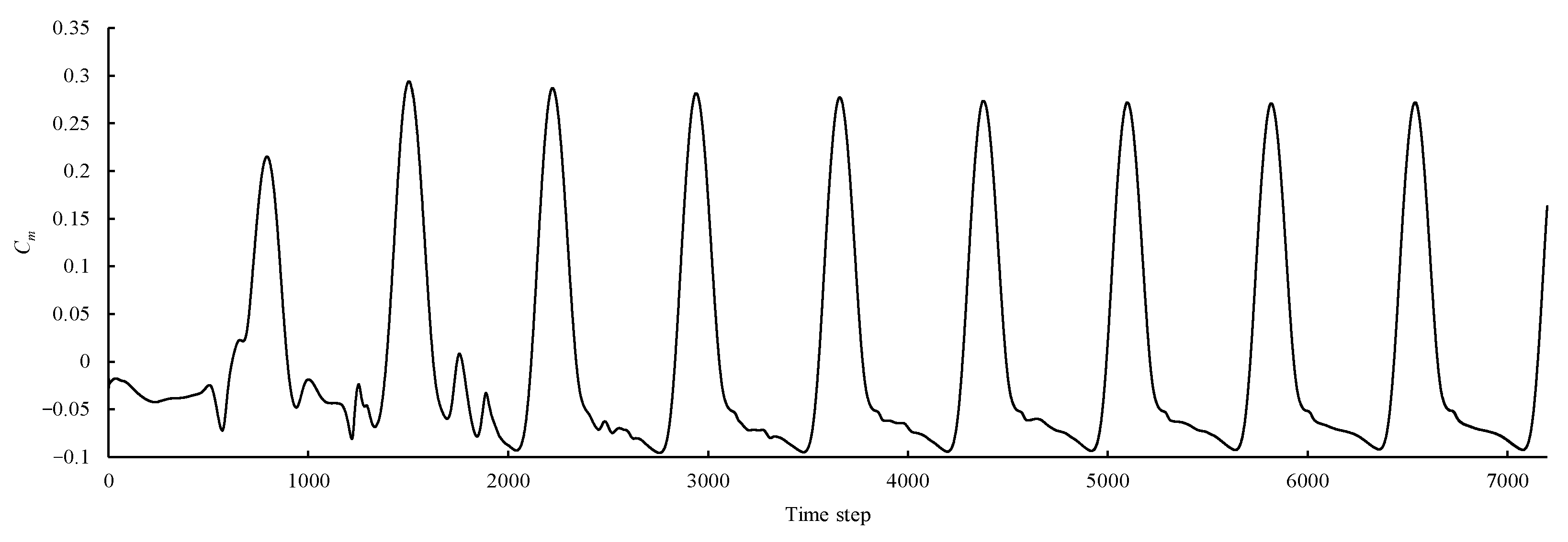
The simulation was set to calculate the tenth cycle. Figure 3 shows the relationship between the instantaneous moment coefficient of a single blade and the number of steps when the wind turbine rotates 10 times when the tip speed ratio is 2. It can be seen that the last two revolutions converged stably.
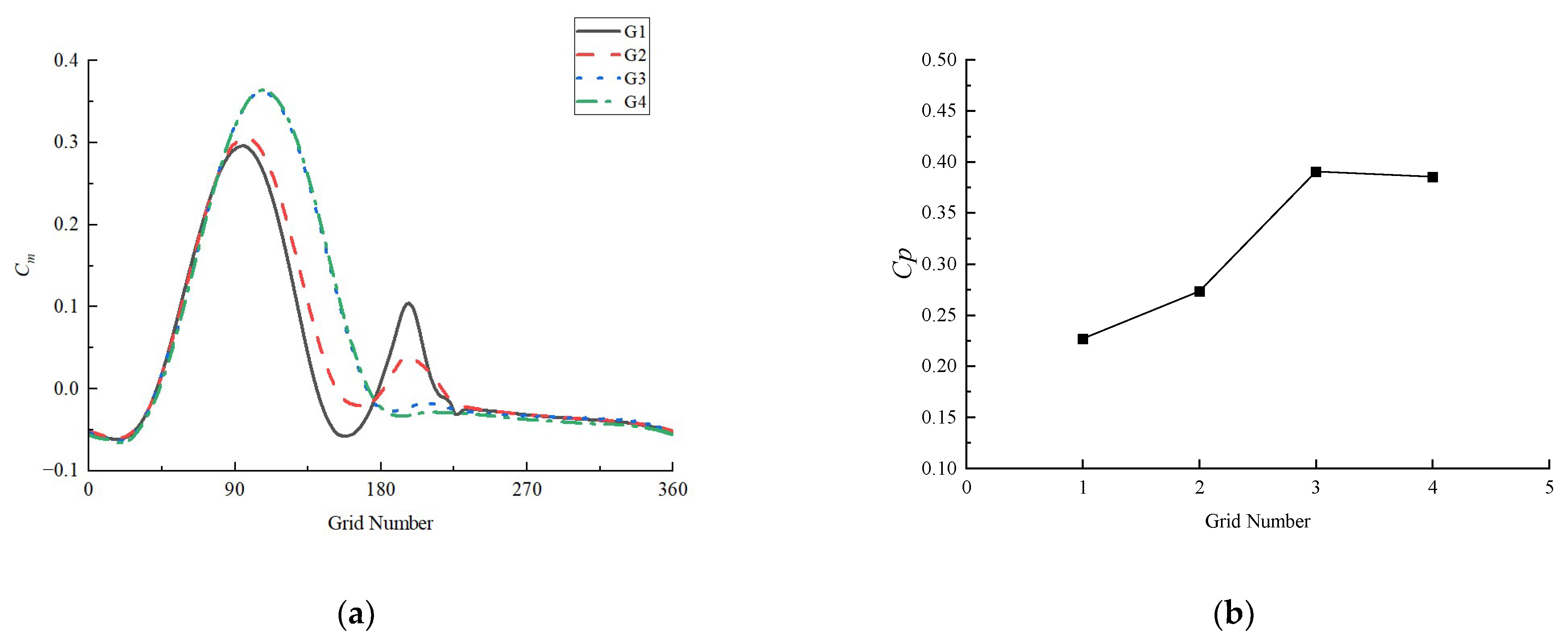
The results of grid number independence verification are shown in Table 3 and Figure 4. Analyzing the tables and figures reveals that as the grid count ascends from G2 to G3, notable alterations occur in the peak value of the moment coefficient curve and the power coefficient. The computed Grid Convergence Index (GCI) registers at 0.0365 (equivalent to 16.07% of the power coefficient), surpassing the predetermined limit. As the grid count escalates from G3 to G4, Figure 4 illustrates a marginal shift in the torque coefficient, with the rate of change in the power coefficient remaining below 1%. The calculated Grid Convergence Index (GCI) stands at 0.0041 (equivalent to 1.05% of the power coefficient), falling below the established 5.0% limit [24]. On the contrary, evaluating the evolving trend in the moment coefficient, the increase in grid count from G3 to G4 involves calculating the root mean square value ε r m s of the relative error Cm, resulting in a mere 1.41%.
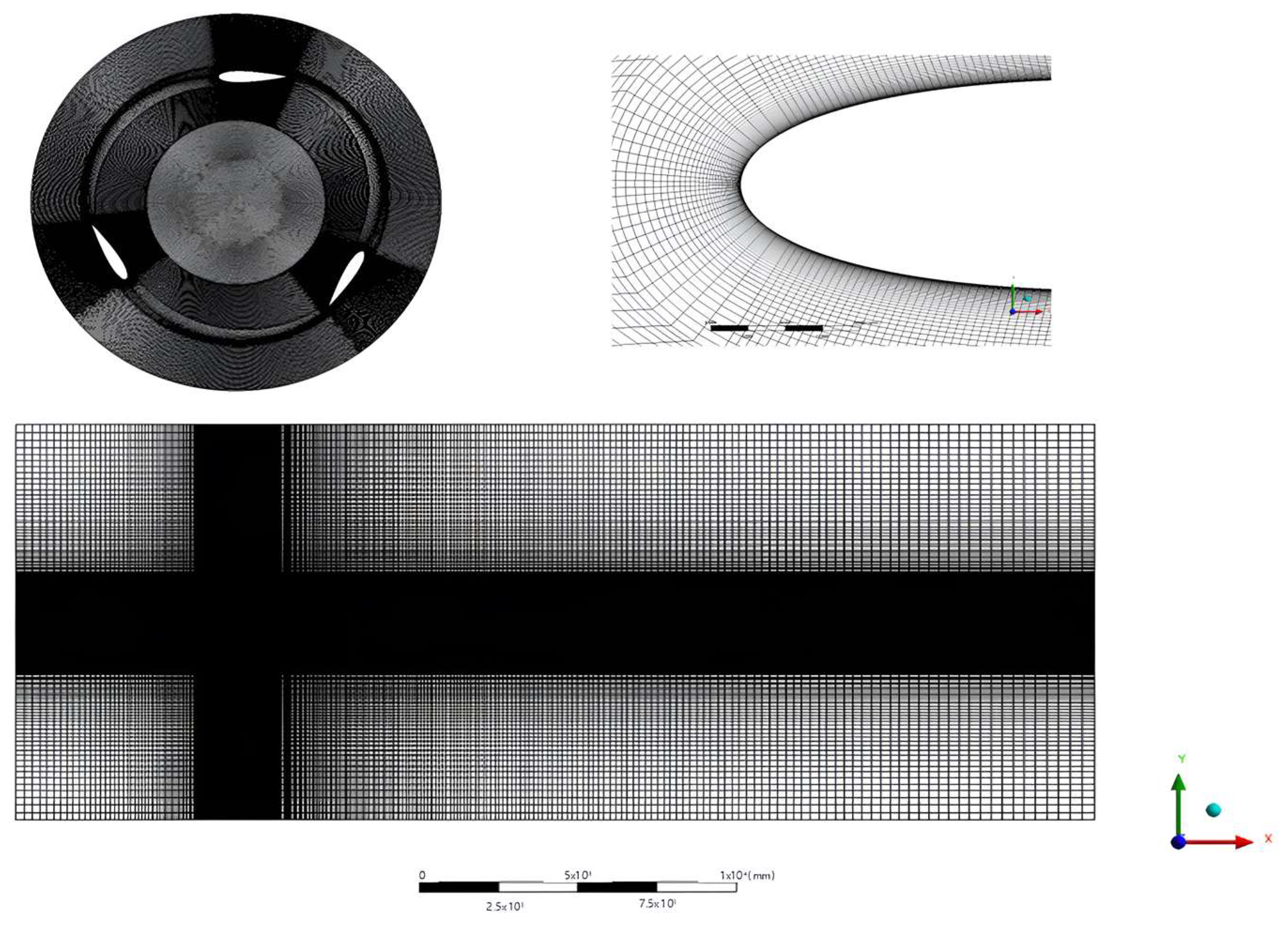
Therefore, considering the precision of grid calculations and the existing computing resources, the G3 grid model was ultimately chosen for the subsequent simulation calculations of the dual VAWTs. The first layer thickness was set at 0.1 mm, comprising a total of 25 layers with a growth rate of 1.1. The grid structure for the entire computational domain is illustrated in Figure 5. The grid undergoes gradual refinement from the outflow static domain to the blade’s near-wall surface to fulfill heightened computational demands.

4.2. Time Step Independence Study

In numerical simulation transient calculations, the significance of time discretization is on par with space discretization. All simulation durations are segmented into equal time steps, with the time interval between two consecutive steps referred to as the time step. An excessively short time step can lead to increased computation time, while an overly long time step may result in the omission of certain transient behaviors, thereby compromising the accuracy of the results. Consequently, employing an appropriately sized time step is imperative for transient simulation, as emphasized in previous studies [25]. To ascertain the independence of the time step, this study utilized the G3 grid model and employed three distinct time steps corresponding to the intervals required for the wind turbine rotation angle to reach 0.5°, 1°, and 1.5°, respectively. Further details can be found in Table 4. We performed calculations for the ten periods based on the three designated time step settings. The correlation between wind turbine speed and time step is illustrated as follows:
ω = 2 π T
n = 60 ω 2 π
t = 60 α × ( 2 π / 360 ) 2 π × n
In the above formulae, T is the rotation period of the wind turbine (s) and α is the corresponding rotation angle (°) of the wind turbine in each time step.
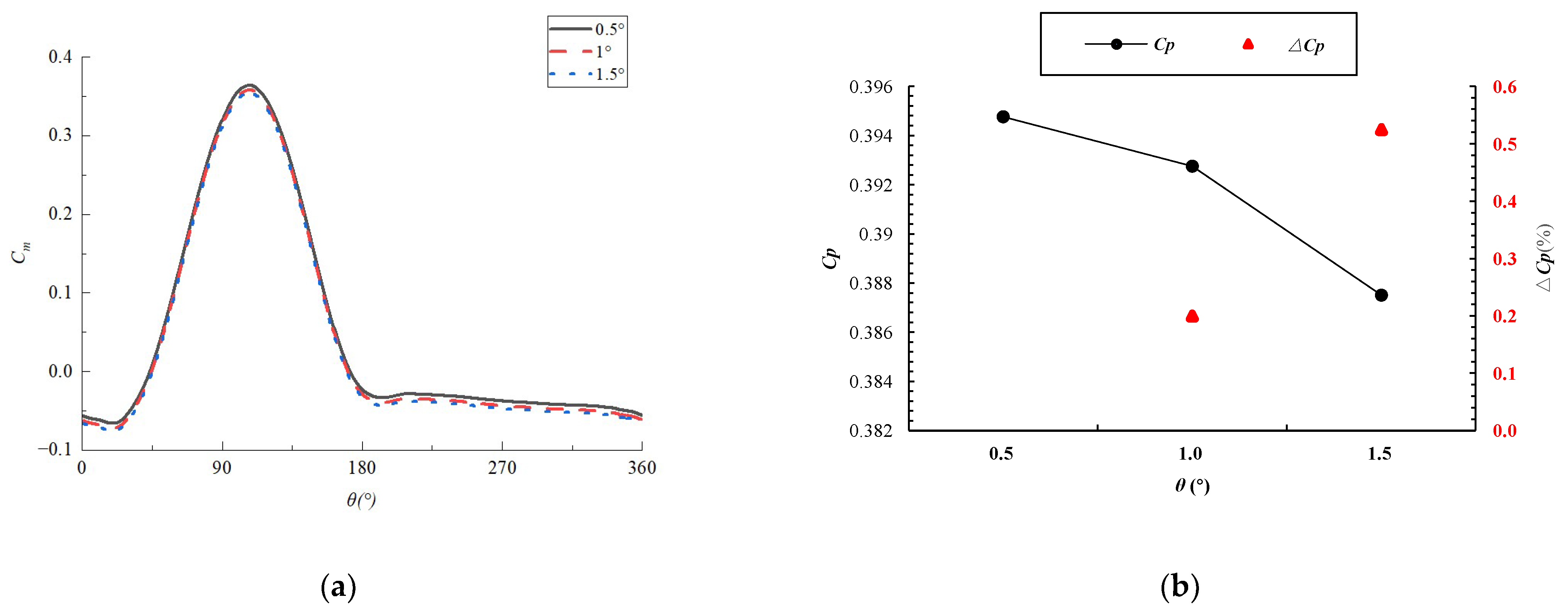
The calculated torque coefficient and power coefficient curves at different time steps are shown in Figure 6. The variation in the moment coefficient highlights a discernible difference at the time steps corresponding to 1.5° and 1°. However, as the refinement progresses from 1° to 0.5°, the disparity between the two becomes remarkably subtle. Simultaneously, in conjunction with Table 5, the relative error calculation results for the power coefficient indicate a 0.525% increase when transitioning from a time step of 1.5° to 1°. Furthermore, the relative root mean square error of the torque coefficient registers at 1.647%. When transitioning from a time step of 1° to 0.5°, the relative error of the power coefficient is merely 0.2%, and the relative root mean square error of the torque coefficient is 0.989%. These values fall within the recommended control indicators for wind turbine simulation. Hence, while ensuring the accuracy of the calculation results and minimizing unnecessary computational overhead and simulation time consumption, the time step for the numerical simulation of the wind turbine was set to correspond to the rotation of the wind turbine by 1°.

4.3. Model Validation

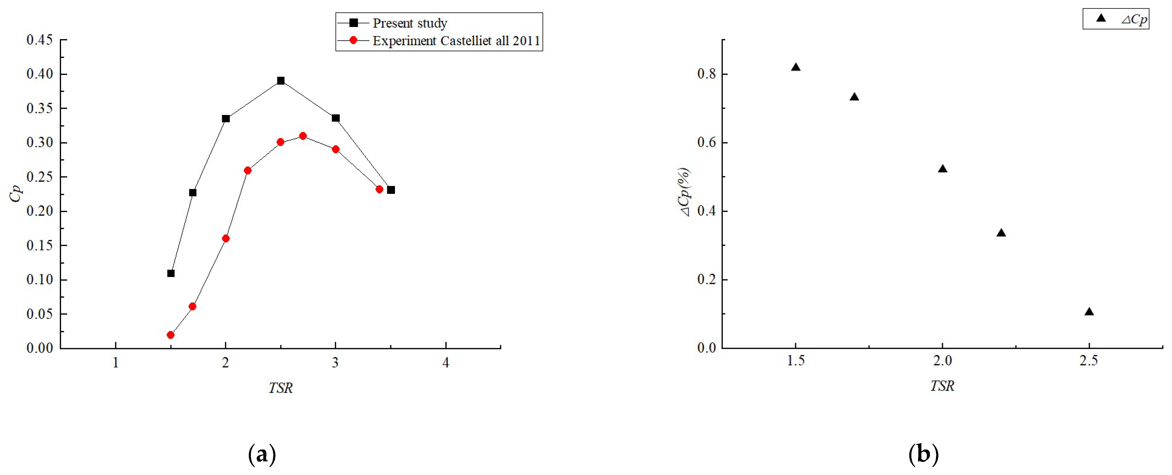
This study identified the optimal model for VAWTs simulation calculations through the use of Fluent software. Subsequently, this model was employed to execute simulations under consistent incoming wind speed U = 5 m/s but varying rotational speeds to derive the relationship between the power coefficient of the wind turbine and the tip speed ratio, commonly denoted as the Cp-TSR relationship curve. To enhance the reliability and precision of the numerical model in this paper, the simulation results were cross-referenced with previous wind tunnel experimental findings [26], as depicted in Figure 7a. Upon comparison, it becomes evident that the two-dimensional single wind turbine model developed in this study more precisely simulates the variations in the power coefficient of the wind turbine across different tip speed ratios. Overall, there is concurrence in the changes observed in the power coefficient between the experiment and the numerical simulation. Prior to the rated TSR = 2.5 of the single wind turbine, the power coefficient exhibits an ascending trend with the tip speed ratio. However, surpassing the rated tip speed ratio leads to an escalation in the tip speed ratio, which leads to a decline in the power coefficient. The comparative analysis not only underscores the efficacy of the numerical model but also substantiates its suitability for predicting the aerodynamic performance of VAWTs.

4.4. Effect of Turbulence Intensity

4.4.1. Self-Start Time

This section investigates the rotational speed during the turbine startup and the torque coefficient when VAWTs are static. From the standpoint of wind energy utilization, the wind turbine attains optimal efficiency in wind energy utilization when the rated TSR is reached, indicating that the startup is successfully accomplished. In accordance with Hill et al. [27], the startup process can be delineated into four stages, as illustrated in Figure 8: During the first stage, the turbine speed undergoes an approximately linear acceleration attributed to drag; in the second stage, the TSR attains a plateau, where the speed experiences minimal increase; in the third stage, the TSR undergoes a rapid increase through lift-driven motion; and in the fourth stage, it reaches its zenith, marking a balanced operational state.
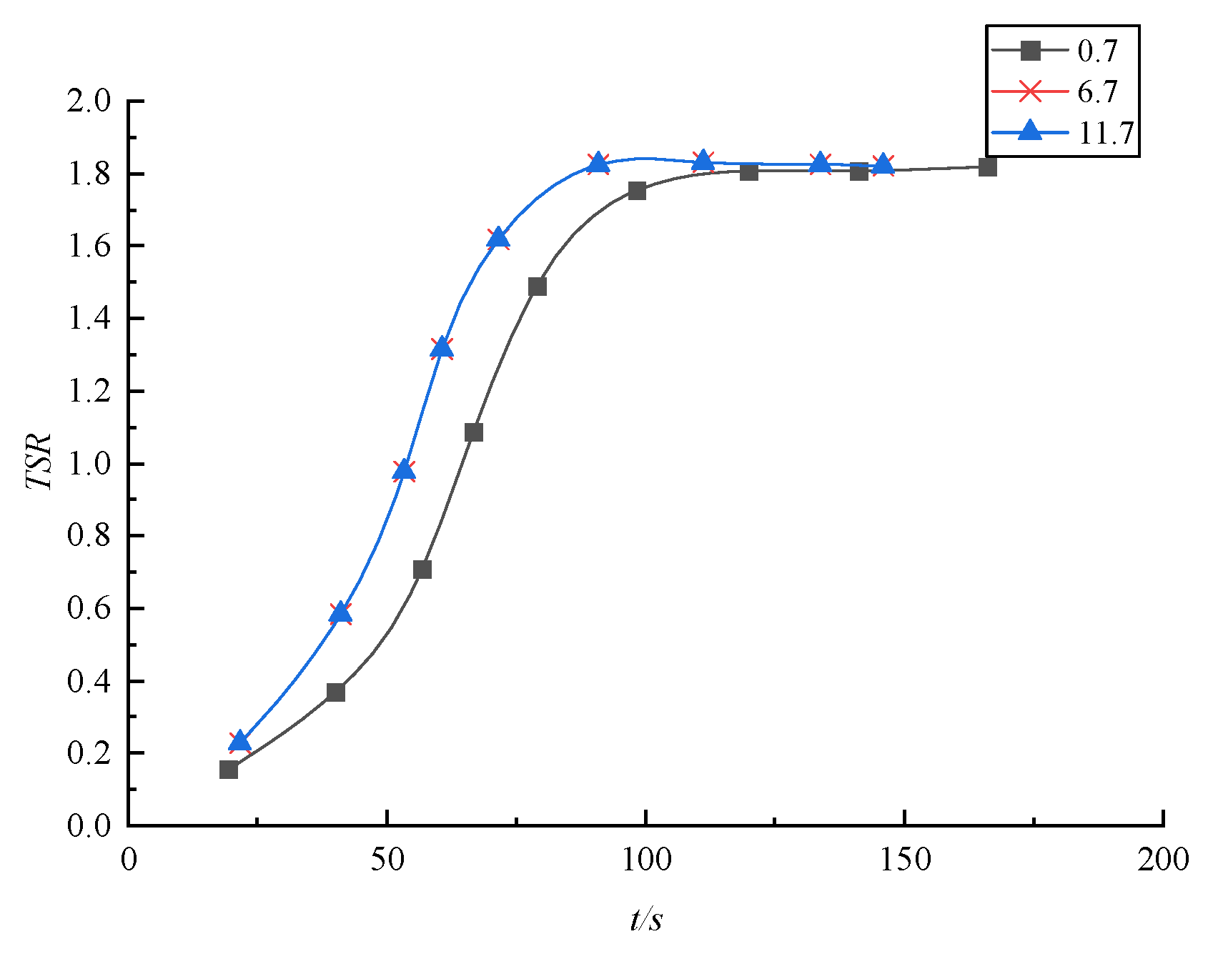
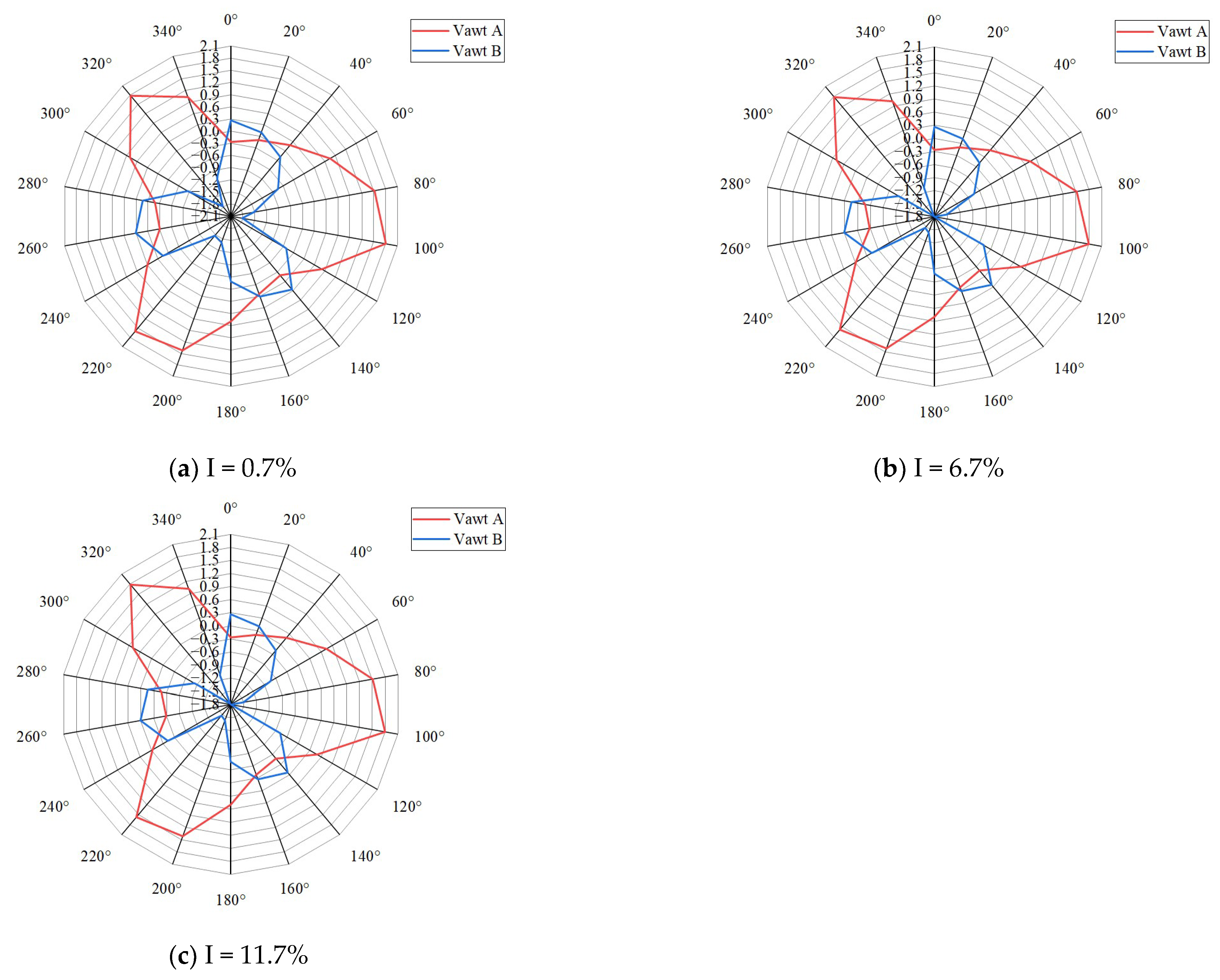
The incremental rise in turbulence intensity exerts a significant influence on the enhancement in the self-starting performance of wind turbines. Illustrated in Figure 9, in scenarios characterized by low turbulence intensity, the wind turbine could be constrained by a comparatively smooth and foreseeable airflow environment during the startup phase, thereby limiting its self-starting capability. Nevertheless, with an escalation in turbulence intensity, the turbulent structure within the wind flow imposes heightened non-uniform aerodynamic excitation on the wind turbine blades. In a turbulent environment, the speed of gas molecules in all directions has large spatiotemporal changes, so the aerodynamic force on the wind turbine blades also shows a more complex spatiotemporal distribution. Figure 10 shows the speed cloud diagram of the wind turbine under different turbulence intensities at the same time. When the turbulence intensity is 0.7%, it is similar to advection. It can be seen from the figure that when the turbulence intensity increases to 6.7%, the maximum wind speed area around the wind turbine expands compared with the advection area, and the wake area decreases. When the turbulence intensity continues to increase and the turbulence intensity is high, the changes in the maximum wind speed area and wake area are not obvious. With further increments in turbulence intensity, there are no significant changes in the maximum wind speed area or wake area. As turbulence intensity increases, this non-uniform excitation becomes more pronounced, contributing additional power input to the wind turbine. This enhanced input assists in overcoming static friction and inertial resistance during the startup phase. In a turbulent environment, the distribution of torque and moment on the blades may undergo alterations, consequently impacting the overall dynamic performance. As depicted in Figure 11, the non-uniformity introduced by turbulence intensifies the variations in torque and moment at various positions on the blades, rendering the wind turbine more adaptable to diverse aerodynamic loads during the startup process [28]. This refined torque distribution is also a contributing factor to the reduced self-start time.

4.4.2. Power (Cp)

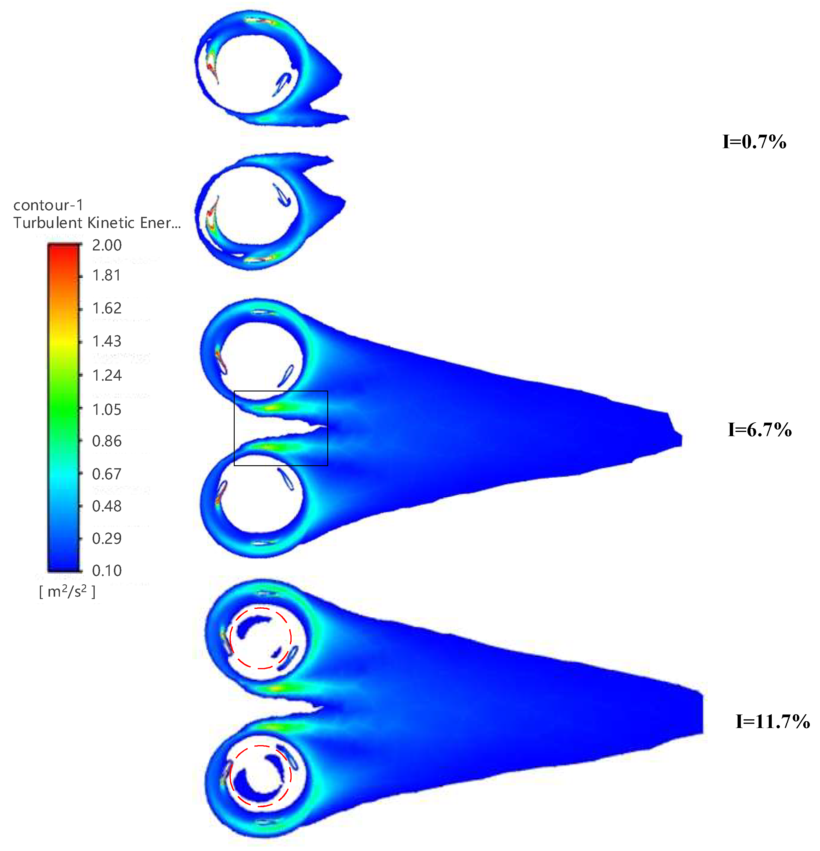
Sun S Y [6] conducted wind tunnel experiments with different turbulence intensities of 0.7%, 6.7%, and 11.7%. This study conducted simulations under the same turbulence intensity to evaluate whether CFD can capture the same behavior. The same turbulence intensity was chosen in this study in order to compare the experimental results with simulation simulations. Turbulence intensity plays a crucial role in determining the performance Cp of a wind turbine and stands as a pivotal factor influencing its efficiency. Variations in turbulence intensity directly impact the local wind speed distribution characteristics, consequently affecting the magnitude of the Cp. The Cp data of wind turbines under different turbulence intensities are shown in Figure 12. The simulation results exhibit a similar trend as the experimental data, indicating an increase in the power coefficient with rising turbulence intensity within a specific range of tip speed ratios. This consistency between the simulated and experimental outcomes not only validates the reliability of the simulation model but also demonstrates the significant impact of turbulence intensity on the power output of the wind turbine. The increment in turbulence intensity is correlated with a progressively intricate and turbulent flow field structure, as evident in the turbulence cloud diagram presented in Figure 13. In conditions of low turbulence intensity, the flow field exhibits a relatively stable state, and the turbulent structure manifests a uniform distribution. Conversely, with an escalation in turbulence intensity, the turbulence cloud image depicts finer-scale and high-frequency changes, indicative of a more tumultuous and irregular evolution of turbulent motion within the flow field. As shown in the dotted circle and solid rectangular box in Figure 13, the development of these turbulent structures directly influences the aerodynamic performance of VAWTs. Under conditions of relatively low turbulence intensity, wind turbines operate within a relatively stable airflow, resulting in a more uniform distribution of aerodynamic loads on their blades [29]. Nevertheless, with the escalation in turbulence intensity, the non-uniformity within the turbulence induces an asymmetrical distribution of loads on the wind turbine blades. This turbulence stimulates the boundary layer of the blades and hinders flow separation on the suction side, consequently postponing the onset of dynamic stall. Although this may lead to increased dynamic oscillations of the blades, it concurrently generates a higher power output from the wind turbine.
An elevation in turbulence intensity implies a more intricate turbulent structure, indicative of a heightened non-uniform motion of gas molecules, consequently intensifying aerodynamic uncertainty. This heightened uncertainty may subject the wind turbine to increased disturbances, but it also endows it with additional kinetic energy [30]. Hence, even though the blades experience more intricate aerodynamic loads, the wind turbine as a whole may demonstrate an elevated power output. It is imperative to note that while heightened turbulence intensity may enhance power output, it also introduces challenges in terms of system dynamics. The operation of wind turbines in environments with high turbulence intensity introduces complexity and necessitates advanced control strategies to ensure system stability. Consequently, heightened turbulence intensity represents both a potential opportunity and a challenge that demands careful consideration and management in the design and operation of VAWTs [31].

5. Conclusions

This study delves into the aerodynamic performance of dual VAWTs under varying turbulence intensities through comprehensive simulation analysis using Ansys Fluent. The findings indicate a notable increase in wind turbine power and a modest enhancement in self-starting performance with escalating turbulence intensity. The turbine’s wind energy utilization rate shows an upward trend with increasing turbulence intensity, resulting in an average power increase of 1.41%. These conclusions bear substantial practical significance for a comprehensive comprehension of the dynamic response of dual VAWTs in turbulent environments, guiding optimization in design and operational control.
The escalation in turbulence intensity amplifies the instantaneous fluctuations in aerodynamic force, particularly in dual VAWTs. The heightened non-uniform aerodynamic excitation prevalent in turbulent environments leads to increased interaction forces between adjacent wind turbines, subjecting blades to more frequent and pronounced non-uniform aerodynamic excitations. This dynamic responsiveness enables the wind turbine to adapt more sensitively to airflow variations in a turbulent environment, effectively harnessing the kinetic energy within the turbulence and enhancing the power output of the wind turbine. This mechanism underlies the correlation between heightened turbulence intensity and increased power output in twin-wind turbines. Simultaneously, the marginal enhancement in the self-starting performance of wind turbines within a turbulent environment suggests that turbulence exerts a certain favorable influence on the initiation process. The non-uniform aerodynamic excitation induced by turbulence facilitates the blades’ ability to overcome static friction and inertial resistance during the starting stage, thereby improving their self-starting performance. This phenomenon holds significant importance in enhancing the reliability of wind turbines in fluctuating turbulent environments, particularly during the low wind speed startup phase.
In conclusion, this study offers a thorough and comprehensive insight into the aerodynamic performance of VAWTs in turbulent environments. This paper employs a two-dimensional numerical analysis method, which simplifies the complexity of the flow field to some extent. While the 2D model offers advantages in computational efficiency, it may not fully capture certain three-dimensional flow characteristics, such as vortices and the three-dimensional effects of fluid flow. While our simulation results are consistent with experimental data in terms of overall trends, the accuracy of the model is dependent on specific experimental conditions and assumptions. Future work may require additional experimental data to further validate and refine the model, particularly under different environmental conditions and turbine designs.

Author Contributions

Conceptualization, Y.Y. and Y.C.; methodology, Y.Y.; software, Y.C.; validation, Y.Y.; formal analysis, Y.Y. and Z.Q.; investigation, Z.Q., X.C. and G.W.; resources, Y.Y., Y.C., J.W. and S.C.; data curation, J.W., Y.Y. and W.Z.; writing—original draft preparation, Y.Y.; visualization, Y.C. and Y.W.; supervision, Y.C. and Y.Z.; project administration, Y.C., Z.Q., Y.Z., W.Z. and Y.W.; funding acquisition, Y.C. All authors have read and agreed to the published version of the manuscript.

Funding

This research was funded by National Natural Science Foundation of China (grant number 51376096), “Fourteenth Five-Year Plan” Provincial Key Construction Discipline Project of Jiangsu Province (2022-0802 Mechanical engineering), and Jiangsu Engineering Research Center for Wind Energy Application.

Institutional Review Board Statement

Not applicable.

Informed Consent Statement

Not applicable.

Data Availability Statement

Some or all data, models, or codes that support the findings of this study are available from the corresponding author upon reasonable request.

Conflicts of Interest

The authors declared no potential conflicts of interest with respect to this research, authorship, and/or publication of this article.

References

  1. Tasnim, M.; Rifa, T.I.; Shahriar, T.; Habib, M.A. Wind Energy Deployment in Bangladesh: Investigating Feasible Locations and Their Characteristics. Energy Rep. 2024, 11, 4338–4355. [Google Scholar] [CrossRef]
  2. Ren, L.; Zhang, W.; Wang, Y.; Wang, H.; Yang, H.; Yao, P.; Zhu, Z. Distribution Characteristics and Assessment of Wind Energy Resources in the Coastal Areas of Guangdong. Sustain. Horizons 2024, 9, 100081. [Google Scholar] [CrossRef]
  3. Bonthu, S.; Purvaja, R.; Singh, K.S.; Ganguly, D.; Muruganandam, R.; Paul, T.; Ramesh, R. Offshore Wind Energy Potential along the Indian Coast Considering Ecological Safeguards. Ocean Coast. Manag. 2024, 249, 107017. [Google Scholar] [CrossRef]
  4. Barzegar-Kalashani, M.; Seyedmahmoudian, M.; Mekhilef, S.; Stojcevski, A.; Horan, B. Small-Scale Wind Turbine Control in High-Speed Wind Conditions: A Review. Sustain. Energy Technol. Assessments 2023, 60, 103577. [Google Scholar] [CrossRef]
  5. Eltayesh, A.; Castellani, F.; Natili, F.; Burlando, M.; Khedr, A. Aerodynamic Upgrades of a Darrieus Vertical Axis Small Wind Turbine. Energy Sustain. Dev. 2023, 73, 126–143. [Google Scholar] [CrossRef]
  6. Sun, S.; Liu, H.; Peng, H. Power Performance and Self-Starting Features of H-Rotor and Helical Vertical Axis Wind Turbines with Different Airfoils in Turbulence. Energy Convers. Manag. 2023, 292, 117405. [Google Scholar] [CrossRef]
  7. Molina, A.C.; De Troyer, T.; Massai, T.; Vergaerde, A.; Runacres, M.C.; Bartoli, G. Effect of Turbulence on the Performance of VAWTs: An Experimental Study in Two Different Wind Tunnels. J. Wind. Eng. Ind. Aerodyn. 2019, 193, 103969. [Google Scholar] [CrossRef]
  8. Abdolahifar, A.; Karimian, S. A Comprehensive Three-Dimensional Study on Darrieus Vertical Axis Wind Turbine with Slotted Blade to Reduce Flow Separation. Energy 2022, 248, 123632. [Google Scholar] [CrossRef]
  9. Abdalrahman, G.; Melek, W.; Lien, F.S. Pitch Angle Control for a Small-Scale Darrieus Vertical Axis Wind Turbine with Straight Blades (H-Type VAWT). Renew. Energy 2017, 114, 1353–1362. [Google Scholar] [CrossRef]
  10. Ni, L.; Miao, W.; Li, C.; Liu, Q. Impacts of Gurney Flap and Solidity on the Aerodynamic Performance of Vertical Axis Wind Turbines in Array Configurations. Energy 2020, 215, 118915. [Google Scholar] [CrossRef]
  11. Hezaveh, S.H.; Bou-Zeid, E.; Dabiri, J.; Kinzel, M.; Cortina, G.; Martinelli, L. Increasing the Power Production of Vertical-Axis Wind-Turbine Farms Using Synergistic Clustering. Bound. -Layer Meteorol. 2018, 169, 275–296. [Google Scholar] [CrossRef]
  12. Kusuma, Y.F.; Fuadi, A.P.; Al Hakim, B.; Sasmito, C.; Nugroho, A.C.P.T.; Khoirudin, M.H.; Priatno, D.H.; Tjolleng, A.; Wiranto, I.B.; Al Fikri, I.R.; et al. Navigating Challenges on the Path to Net Zero Emissions: A Comprehensive Review of Wind Turbine Technology for Implementation in Indonesia. Results Eng. 2024, 22, 102008. [Google Scholar] [CrossRef]
  13. Li, G.; Li, Y.; Li, J.; Huang, H.; Huang, L. Research on Dynamic Characteristics of Vertical Axis Wind Turbine Extended to the Outside of Buildings. Energy 2023, 272, 127182. [Google Scholar] [CrossRef]
  14. Dabiri, J.O. Potential Order-of-Magnitude Enhancement of Wind Farm Power Density via Counter-Rotating Vertical-Axis Wind Turbine Arrays. J. Renew. Sustain. Energy 2011, 3, 043104. [Google Scholar] [CrossRef]
  15. Golarcheh, A.; Anbarsooz, M.; Benini, E. An Actuator Line Method for Performance Prediction of HAWTs at Urban Flow Conditions: A Case Study of Rooftop Wind Turbines. Energy 2024, 292, 130268. [Google Scholar] [CrossRef]
  16. Bianchini, A.; Balduzzi, F.; Bachant, P.; Ferrara, G.; Ferrari, L. Effectiveness of Two-Dimensional CFD Simulations for Darrieus VAWTs: A Combined Numerical and Experimental Assessment. Energy Convers. Manag. 2017, 136, 318–328. [Google Scholar] [CrossRef]
  17. Fertahi, S.E.-D.; Samaouali, A.; Kadiri, I. CFD Comparison of 2D and 3D Aerodynamics in H-Darrieus Prototype Wake. E-Prime Adv. Electr. Eng. Electron. Energy 2023, 4, 100178. [Google Scholar] [CrossRef]
  18. Zhang, Z.; Liu, L.; Shi, Y.; Zhang, K.; Liu, K.; Wang, S.; Hu, F. Analysis of Urban Turbulence Intensity Observed by Beijing 325-m Tower and Comparison with the IEC Turbulence Model for Small Wind Turbines. J. Wind. Eng. Ind. Aerodyn. 2023, 241, 105511. [Google Scholar] [CrossRef]
  19. Maalouly, M.; Souaiby, M.; ElCheikh, A.; Issa, J.; Elkhoury, M. Transient analysis of H-type Vertical Axis Wind Turbines using CFD. Energy Rep. 2022, 8, 4570–4588. [Google Scholar] [CrossRef]
  20. Shen, Z.; Gong, S.; Xie, G.; Lu, H.; Guo, W. Investigation of the Effect of Critical Structural Parameters on the Aerodynamic Performance of the Double Darrieus Vertical Axis Wind Turbine. Energy 2023, 290, 130156. [Google Scholar] [CrossRef]
  21. Ye, M.; Zhao, Y.; Chen, H.C.; Wan, D. Quantification of Numerical Uncertainties of CFD-Predicted Wind Turbine Performance with Overset Grids. Ocean. Eng. 2024, 298, 117231. [Google Scholar] [CrossRef]
  22. Shukla, S.; Ramanan, C.; Bora, B.J.; Deo, A.; Alom, N. Numerical analysis of vertical axis wind turbine blades in ANSYS Fluent. Mater. Today Proc. 2022, 59, 1781–1785. [Google Scholar] [CrossRef]
  23. Roache, P.J. Quantification of Uncertainty in Computational Fluid Dynamics. Annu. Rev. Fluid Mech. 1997, 29, 123–160. [Google Scholar] [CrossRef]
  24. Khedr, A.; Castellani, F. Critical Issues in the Moving Reference Frame CFD Simulation of Small Horizontal Axis Wind Turbines. Energy Convers. Manag. X 2024, 22, 100551. [Google Scholar] [CrossRef]
  25. Mahato, A.; Singh, R.K.; Barnwal, R.; Rana, S.C. Aerodynamic Characteristics of NACA 0012 vs. NACA 4418 Airfoil for Wind Turbine Applications through CFD Simulation. Mater. Today Proc. 2023, 22, 53–69. [Google Scholar] [CrossRef]
  26. Castelli, M.R.; Englaro, A.; Benini, E. The Darrieus Wind Turbine: Proposal for a New Performance Prediction Model Based on CFD. Energy 2011, 36, 4919–4934. [Google Scholar] [CrossRef]
  27. Chegini, S.; Asadbeigi, M.; Ghafoorian, F.; Mehrpooya, M. An Investigation into the Self-Starting of Darrieus-Savonius Hybrid Wind Turbine and Performance Enhancement through Innovative Deflectors: A CFD Approach. Ocean Eng. 2023, 287, 115910. [Google Scholar] [CrossRef]
  28. Li, L.; Wang, B.; Ge, M.; Huang, Z.; Li, X.; Liu, Y. A Novel Superposition Method for Streamwise Turbulence Intensity of Wind-Turbine Wakes. Energy 2023, 276, 127491. [Google Scholar] [CrossRef]
  29. Yossri, W.; Ben Ayed, S.; Abdelkefi, A. Evaluation of the Efficiency of Bioinspired Blade Designs for Low-Speed Small-Scale Wind Turbines with the Presence of Inflow Turbulence Effects. Energy 2023, 273, 127210. [Google Scholar] [CrossRef]
  30. Liu, S.; Li, Q.; Lu, B.; He, J. Analysis of NREL-5MW Wind Turbine Wake under Varied Incoming Turbulence Conditions. Renew. Energy 2024, 224, 120136. [Google Scholar] [CrossRef]
  31. Zhang, Y.; Li, Z.; Liu, X.; Sotiropoulos, F.; Yang, X. Turbulence in Waked Wind Turbine Wakes: Similarity and Empirical Formulae. Renew. Energy 2023, 209, 27–41. [Google Scholar] [CrossRef]
Figure 1. Schematic diagram of the simplified two-dimensional model of a wind turbine.
Energies 17 04124 g001
Figure 2. Schematic diagram of the calculation area of the dual VAWTs numerical model.
Energies 17 04124 g002
Figure 3. Instantaneous moment coefficient for the full 10 turbine revolutions.
Energies 17 04124 g003
Figure 4. Verification of grid number: (a) torque curves with different grid numbers and (b) power with different grid numbers.
Energies 17 04124 g004
Figure 5. Meshing.
Figure 5. Meshing.
Energies 17 04124 g005
Figure 6. (a) Torque coefficient and (b) power coefficient at different time steps.
Energies 17 04124 g006
Figure 7. (a) Comparison of experimental and simulated Cp-TSR curves [26]. (b) Comparison of experimental and simulated ∆Cp-TSR curves.
Energies 17 04124 g007
Figure 8. Schematic diagram of the wind turbine startup process.
Energies 17 04124 g008
Figure 9. TSR changes with time under different turbulence intensities.
Energies 17 04124 g009
Figure 10. Wind turbine speed cloud diagram at the same time under different turbulence intensities.
Energies 17 04124 g010
Figure 11. Torque changes at different positions on the blade under different turbulence intensities: (a) I = 0.7%; (b) I = 6.7%, and (c) I = 6.7%.
Energies 17 04124 g011
Figure 12. The Cp of the wind turbine under different turbulence intensities [6].
Energies 17 04124 g012
Figure 13. Turbulent kinetic energy diagram under different turbulence intensities.
Energies 17 04124 g013
Table 1. Relevant geometric characteristic parameters of wind turbines.
FeatureValue
AirfoilNACA0018
Chord (c)0.172 m
Number of blades (N)3
Rotor diameter (D)0.68 m
Table 2. Number of grids in different areas.
Grid NumberInternal Rotation
Domain
External Stationary DomainEntire Computational Domain
G159,85035,15095,000
G2108,81965,181174,000
G3289,088170,512459,600
G4837,199493,8011,331,000
Table 3. Verification of independence of the number of wind turbine grids.
Grid NumberCpGCI ε r m s (%)
G10.2270.0365 (16.07%)8.1
G20.2730.0924 (33.8%)17.14
G30.3890.0041 (1.05%)1.41
G40.386--
Table 4. One-step rotation angle and corresponding time step of the wind turbine.
Time Step (s)Rotation Angle (°)Number of Time Steps in a Cycle
0.000 244 3480.5720
0.000 305 4321360
0.000 407 2431.5240
Table 5. Time step independence verification.
The Time Step Corresponds to the Rotation Angle (°)CpCp (%) ε r m s (%)
0.50.3940.20.989
10.3920.5251.647
1.50.387--
Disclaimer/Publisher’s Note: The statements, opinions and data contained in all publications are solely those of the individual author(s) and contributor(s) and not of MDPI and/or the editor(s). MDPI and/or the editor(s) disclaim responsibility for any injury to people or property resulting from any ideas, methods, instructions or products referred to in the content.