Article

Calculation Method of Three-Phase Productivity of Horizontal Well in Water-Bearing Condensate Gas Reservoir

PetroChina Research Institute of Petroleum Exploration and Development, Beijing 100083, China
*
Author to whom correspondence should be addressed.
Energies 2024, 17(12), 2932; https://doi.org/10.3390/en17122932
Submission received: 19 April 2024 / Revised: 4 June 2024 / Accepted: 5 June 2024 / Published: 14 June 2024
(This article belongs to the Special Issue Development of Unconventional Oil and Gas Fields)

Abstract

:
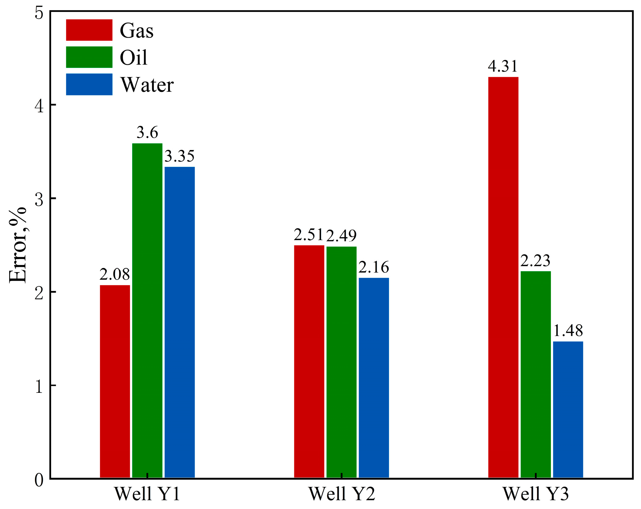
Condensate gas reservoirs are a special kind of reservoir because of the presence of multiphase flow in their production. The accurate calculation of the multiphase flow productivity in horizontal wells is of great significance for reservoir development. In this study, the total pseudopressure and the equivalent total flow are defined to solve the multiphase nonlinear problem in the oil–gas–water three-phase control flow equation, and to establish a three-phase productivity equation considering the non-Darcy effect. It provides a solution for the three-phase productivity calculation of horizontal wells in water-bearing condensate gas reservoirs. The example verification and error analysis of three horizontal wells, except for the gas production error of Well Y3 and the average error of the production data of other gas wells, is below 4%. The fitting effect of Well Y2 is better than that of the other two horizontal wells, and the average error of the oil, gas, and water phases is below 3%. This method provides a practical and simple engineering tool for the analysis of the productivity of condensate gas reservoirs considering multiphase flow.

1. Introduction

Condensate gas reservoirs are characterized by complex flow mechanisms. The exploitation of this kind of reservoir can not only extract natural gas from the formation, but also extract crude oil [1,2,3,4]. Gas condensate reservoirs have become a reasonably reliable source of energy, so the development of gas condensate reservoirs plays an important role in the petroleum industry.
Gas condensate reservoirs are different from the conventional reservoir systems; when the gas condensate reservoir pressure drops below the dew point pressure, the heavy components of the condensate gas begin to condense and become the liquid phase [5,6,7,8]. Therefore, liquid condensate will accumulate near the wellbore, which will seriously damage the productivity of gas wells [9,10,11,12]. It is of great significance to study the production performance well in gas condensate reservoirs.
Much effort has been made to calculate the productivity of gas wells. Fussel described the phenomenon of condensate oil blockage in condensate gas reservoirs [13]. Condensate oil precipitation is considered to be a near-well pollution, which will lead to an increase in the skin factor around the well. Therefore, the value of the skin factor can be changed to characterize the effect of the near-well oil blockage.
Thompson et al. proposed a two-region flow model: (1) the inner region: here, there are two gas–oil phases; (2) the outer region: here, there is only gas phase flow, and no condensate oil is produced [14]. Compared with the blockage effect, the two-region flow model more accurately describes the influence of the precipitation of retrograde condensate in the formation on the seepage, but does not take into account the transition between the two flow regions.
Afidick et al. conducted a constant component expansion (CCE) experiment, which showed that even in gas condensate reservoirs, in which the maximal liquid dropout in the experiment was as low as 1%, liquid blockage around the wellbore can lead to a significant reduction in gas production [15].
Through the numerical simulation of the production dynamics of the condensate gas reservoir, Fevang and Whitson proposed a three-region model based on the change in the production gas/oil ratio: (1) the inner region, where the oil and gas phases can flow at different speeds; (2) the transition region, where condensate oil exists but cannot flow, and only gas phase can flow; and (3) the outer region, where only the gas phase flows [16]. This model more accurately shows the distribution of the oil and gas phases in condensate gas reservoirs, and is widely used in calculation and numerical simulation [17,18,19,20,21]. According to this method, many scholars have studied the productivity of vertical wells in condensate gas reservoirs [6,8,22]. Some scholars have further established the four-region model [23,24,25,26,27], which takes into account the capillary effect and is the most comprehensive method; however, it increases the difficulty of modeling.
The focus of the research in this paper is horizontal wells. Horizontal wells can increase the contact area with the reservoir and reduce the production differential pressure, so horizontal wells have the effect of reducing the formation of condensate in the near-well region in condensate reservoirs [24,28,29,30,31,32].
Mott proposed a method for engineering the calculation of condensate gas well production, which takes into account a material balance model under pressure depletion and a two-phase fitted pressure integral of the well inflow dynamics, with the integral term incorporating high-velocity effects and changes in fluid composition due to formation condensate-enriched zones, and which allows for the prediction of gas well production much faster than numerical simulation calculations [33].
Li et al. proposed a semi-analytical model that can combine pressure–volume–temperature (PVT) characteristics with the production pressure [18]. In the sensitivity analysis, the reorganization score has a large influence. The model provides a new method for solving transient pressure in gas reservoirs, but it does not analyze the productivity of condensate gas wells. In 2018, Ghahri et al. simulated the multiphase flow around horizontal wells in condensate gas reservoirs [34]. The flow behavior around wells is quantified by the effective wellbore radius of the equivalent open hole, but the influence of water is not considered in the model. Behmanesh et al. presented a simple yet semi-analytical model that provides a solution for analyzing production data from wells exhibiting multiphase flow during boundary-dominated flow periods; however, the model does not consider the influence of heterogeneity [2]. Zhang et al. proposed a three-zone model centered on five horizontal wells through the Laplace transform, and their model can effectively predict condensate gas reservoirs, but the model ignores the influence of water [21].
From the above literature review, there are very limited publications that have discussed the method of the three-phase productivity of horizontal wells in water-bearing condensate gas reservoirs. In this work, we present a simple model that provides a solution for analyzing production data from wells exhibiting multiphase flow. An appropriately defined total pseudopressure is introduced to handle the associated multiphase nonlinearities in the governing flow equations of the oil, gas, and water phases simultaneously. The model provides a theoretical framework for analyzing production data from condensate reservoirs, considering multiphase flow.

2. Methodology

2.1. Basic Assumptions

In this study, it is considered that there are three phases of oil, gas, and water in the formation, which can flow simultaneously, as shown in Figure 1. In order to develop a mathematical model describing the flow and production of horizontal wells in water-bearing condensate gas reservoirs, some assumptions are made, as follows:
(1)
The reservoir is horizontal and with uniform thickness;
(2)
The gravity force and the capillary force are neglected;
(3)
The flow of reservoir fluids is assumed to be isothermal;
(4)
Gas and water are immiscible with each other; gas and oil are miscible with each other;
(5)
The horizontal well is producing at a constant mass flow rate at the surface condition.

2.2. Mathematical Modeling of Three-Phase Flow

2.2.1. Governing Equations

The pressure drop of horizontal wells is usually smaller than that of vertical wells. This pressure change is usually quantified in terms of a skin, or an effective wellbore radius, included in the well productivity calculation of an equivalent open hole system [34,35,36]. In this study, a total skin S is used to characterize this effect. Therefore, the productivity of horizontal wells is equivalent to the productivity of vertical wells with a skin effect.
The three-component model can be used to represent the multiphase flow in the reservoir. Combining Darcy’s law with the continuity equation, a mathematical model describing the flow of gas, oil, and water can be obtained. The three-phase flow equations in the radial coordinate of the condensate gas reservoir are as follows [37,38]:
Gas   Phase : 1 r r K rg μ g B g + R s K ro μ o B o r p r = ϕ K t S g B g + R s S o B o
Oil   Phase : 1 r r K ro μ o B o + R v K rg μ g B g r p r = ϕ K t S o B o + R v S g B g
Water   Phase : 1 r r K rw μ w B w r p r = ϕ K t S w B w
where r is the radial distance; p is the reservoir pressure, Krj is the phase (gas, oil, water) relative permeability, μj is the phase viscosity; Bj is the phase formation volume factor (FVF); Rv is the solution oil/gas ratio; Rs is the solution gas/oil ratio; S is the phase saturation; ϕ is the reservoir porosity; K is the reservoir permeability.
Define the gas phase pseudopressure as
ψ ( r , t ) = p w p e K rg μ g B g + R s K ro μ o B o d p
The pseudopressure equation considering the skin factor is
ψ ( r   e , t ) ψ ( r   w , t ) = q g 2 π K h ln r e r w + S
Combining Equations (4) and (5) derives
Gas   phase : p w p e K rg μ g B g + R s K ro μ o B o d p = q g 2 π K h ln r e r w + S
A similar equation can be developed for oil and water:
Oil   phase : p w p e K ro μ o B o + R v K rg μ g B g d p = q o 2 π K h ln r e r w + S
Water   phase : p w p e K rw μ w B w d p = q w 2 π K h ln r e r w + S
The total mass flow rate is obtained by multiplying the flow rate of gas, oil, and water by the corresponding phase density under standard conditions.
m total = m o + m g + m w = q o ρ o s c + q g ρ g s c + q w ρ w s c
where ρjsc is the phase (gas, oil, water) density; qj is the phase flow rate; mj is the phase mass flow rate; mtotal is the total mass flow rate; pe is the initial reservoir pressure; pw is the reservoir pressure at rw; h is the reservoir thickness; S is the skin factor.
An equivalent total flow rate, qe, can be defined by dividing both sides of Equation (9) by the reference density. The gas density at standard conditions is selected as the reference density for a condensate reservoir.
q e = m total ρ ref = ρ o s c ρ ref q o + ρ g s c ρ ref q g + ρ w s c ρ ref q w
The total pseudopressure function can be defined as
ψ e ψ w = p w p e ρ o s c ρ ref K ro μ o B o + R v K rg μ g B g + ρ g s c ρ ref K rg μ g B g + R s K ro μ o B o + ρ w s c ρ ref K rw μ w B w d p
Combining Equations (6)–(11) derives
ψ e ψ w = q e 2 π K h ln r e r w + S
For the non-Darcy term, according to the Forchheimer equation, this corresponds to an increase in the non-Darcy flow pressure drop, expressed in terms of the proposed pressure as
Δ ψ n = q e 2 4 π 2 h 2 r w r ρ g s c ρ ref K rg μ g B g + R s K ro μ o B o β f   g 2 1 r 2 d r
where
f g = q g q e
Combining Equations (13) and (14) derives
ψ e ψ w = q e 2 π K h ln r e r w + S + q e 2 4 π 2 h 2 r w r e ρ g s c ρ ref K rg μ g B g + R s K ro μ o B o β f g 2 1 r 2 d r
where Ψe is the total pseudopressure at re; Ψw is the total pseudopressure at rw; qe is the equivalent total flow rate; β is the inertial drag coefficient of the gas; ρref is the reference density.
For convenience, the A and B variables are defined as
A = 1 4 π 2 h 2 r w r e ρ g s c ρ ref K rg μ g B g + R s K ro μ o B o β f g 2 1 r 2 d r
B = 1 2 π K h ln r e r w + S
Combining Equations (15)–(17), the three-phase productivity equation is
ψ e ψ w = A q e 2 + B q e

2.2.2. Constraint Conditions

According to the characteristics of the above three-phase abortion energy model of condensate gas reservoirs, the following constraint conditions for describing the production of condensate gas in horizontal wells can be obtained:
(i) Initial conditions:
p ( r , t ) t = 0 = p i
(ii) Outer boundary conditions:
p ( t , r ) r = r e = p i
(iii) Inner boundary condition:
Gas   phase : q g ( t ) = 2 π K h K rg μ g B g + R s K ro μ o B o r p r r = r w
Oil   phase : q o ( t ) = 2 π K h K ro μ o B o + R v K rg μ g B g r p r r = r w
Water   phase : q w ( t ) = 2 π K h K rw μ w B w r p r r = r w
where pi is the initial formation pressure; qg, qo, qw are the productivities of gas, oil, and water.

3. Model Solution

The total pseudopressure is the basis for solving multiphase flow productivity in condensate gas reservoirs. The pseudopressure can be evaluated if the relationship between the fluid saturation and pressure is established, which is the Saturation Pressure (SP) path. The SP path depends on many factors, including the boundary conditions, well production regime, flow geometry and phase behavior, and so on.
When the formation is a two-phase steady-state flow of oil and gas, the gas/oil ratio (GOR) is a constant, and equals the produced wellstream GOR, which can be expressed by the following equation:
G O R = k r o μ o B o R s + k r g μ g B g k r o μ o B o + k r g μ g B g R ν
The relationship between the fluid saturation and pressure can be expressed by the following equation containing the GOR:
k r g k r o ( p ) = G O R R s 1 R v G O R μ g B g μ o B o
Equation (25) gives k r g k r o ( p ) , where the relationship of k r g k r o with the pressure is shown. Through the relative permeability curve, the relationship between krg, kro, and saturation can be obtained, and the SP path can be obtained by combining these two relationships.
However, when there is oil, gas, and water three-phase flow in the reservoir, in addition to the GOR, the water/oil ratio (WOR) information is also needed to correlate the pressure and saturation. The problem to be solved in the three-phase flow is the obtention of the relative permeability krg, kro, and krw, which depend on the three saturations Sg, So, and Sw, while the production of the GOR and WOR in the wellbore can provide the saturations of oil, gas, and water [26]. In order to solve the SP path, the variables x and y are defined as
x = 1 1   +   G O R
y = W O R 1   +   G O R   +   W O R
Combined with Equations (6)–(8), (26), and (27), the relationship between the oil, gas, and water saturation can be obtained as follows:
f 1 ( S g , S w ) = 1 x k r o μ o B o 1 1 x k r g μ g B g = 0
f 2 ( S g , S w ) = 1 x k r o μ o B o 1 y y k r w μ w B w = 0
Equations (28) and (29) are nonlinear equations with two unknowns, Sg and Sw, which can be solved by the root-finding algorithm. The oil saturation can be solved using the following equation:
S o = 1 S g S w
The viscosity, density, and volume coefficient of the gas, oil, and water under different pressures can be determined by PVT experiments. The relation of saturation with pressure can be obtained by Equations (28)–(30) combined with the phase permeability curve.
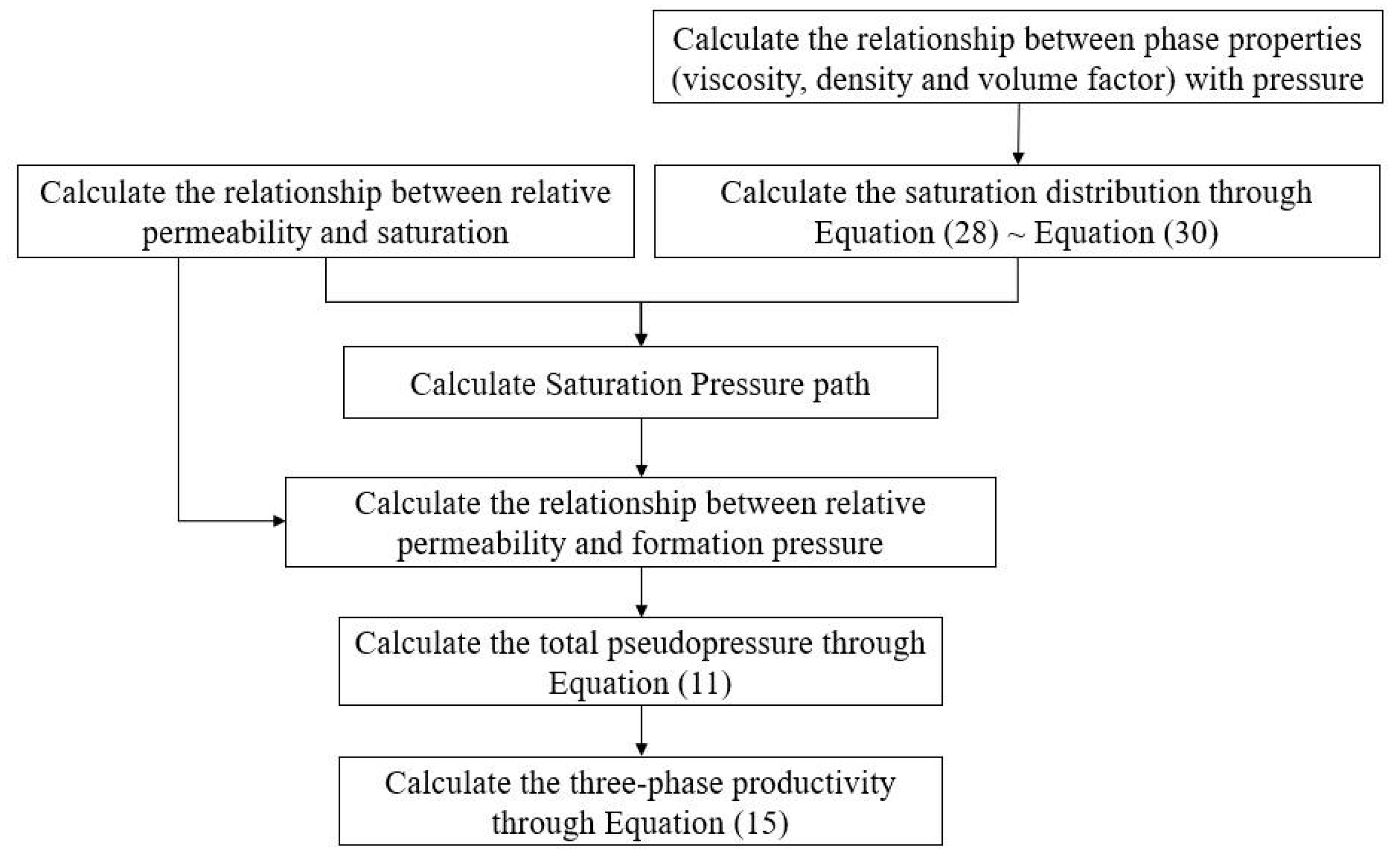
The flow chart of the three-phase abortion energy model of a condensate gas reservoir is shown in Figure 2. The relative permeability, density, viscosity, and volume factor are all functions of pressure. Based on the relationship between saturation and pressure, combined with the relative permeability curve, the relationship between saturation and pressure is established, and then the total pseudopressure function can be solved by numerical integration method. Combined with the production data, the equivalent total flow rate is calculated, and the productivity equation is determined by regression.

4. Case Validation and Discussion

For the field case analysis of a horizontal well in a water-bearing condensate gas reservoir, three horizontal wells (Y1, Y2, Y3) in the TP21 gas reservoir are selected. The TP21 gas reservoir is a water-bearing condensate gas reservoir and horizontal Well Y produces three fluids of oil, gas, and water at the same time. The basic parameters of the reservoir are shown in Table 1. The relative permeability is presented in Figure 3.
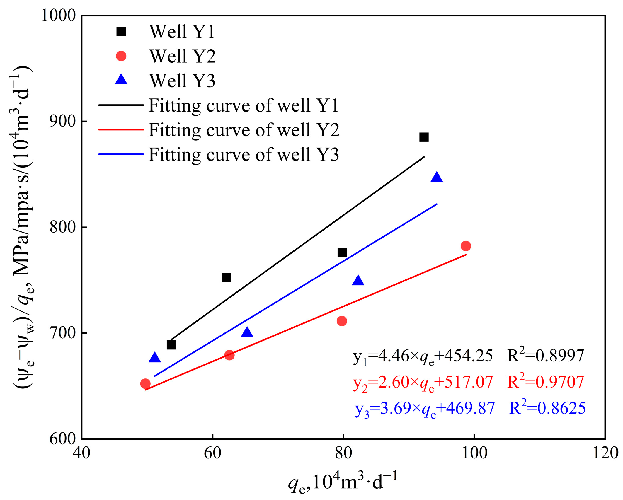
The total pseudopressure and equivalent total flow of the gas wells are calculated, and the plot of (ΨeΨw)/qe vs. qe is drawn (Figure 4). By fitting the relationship between the (ΨeΨw)/qe and qe, the productivity equation of the three wells is established to predict the productivity of the gas wells.
According to the coefficient of the fitting curve in Figure 4, the productivity equations of horizontal wells Y1, Y2, and Y3 are as follows:
ψ e 1 ψ w 1 = 4.46 q e 2 + 454.25 q e
ψ e 2 ψ w 2 = 2.60 q e 2 + 517.07 q e
ψ e 3 ψ w 3 = 3.691 q e 2 + 469.87 q e
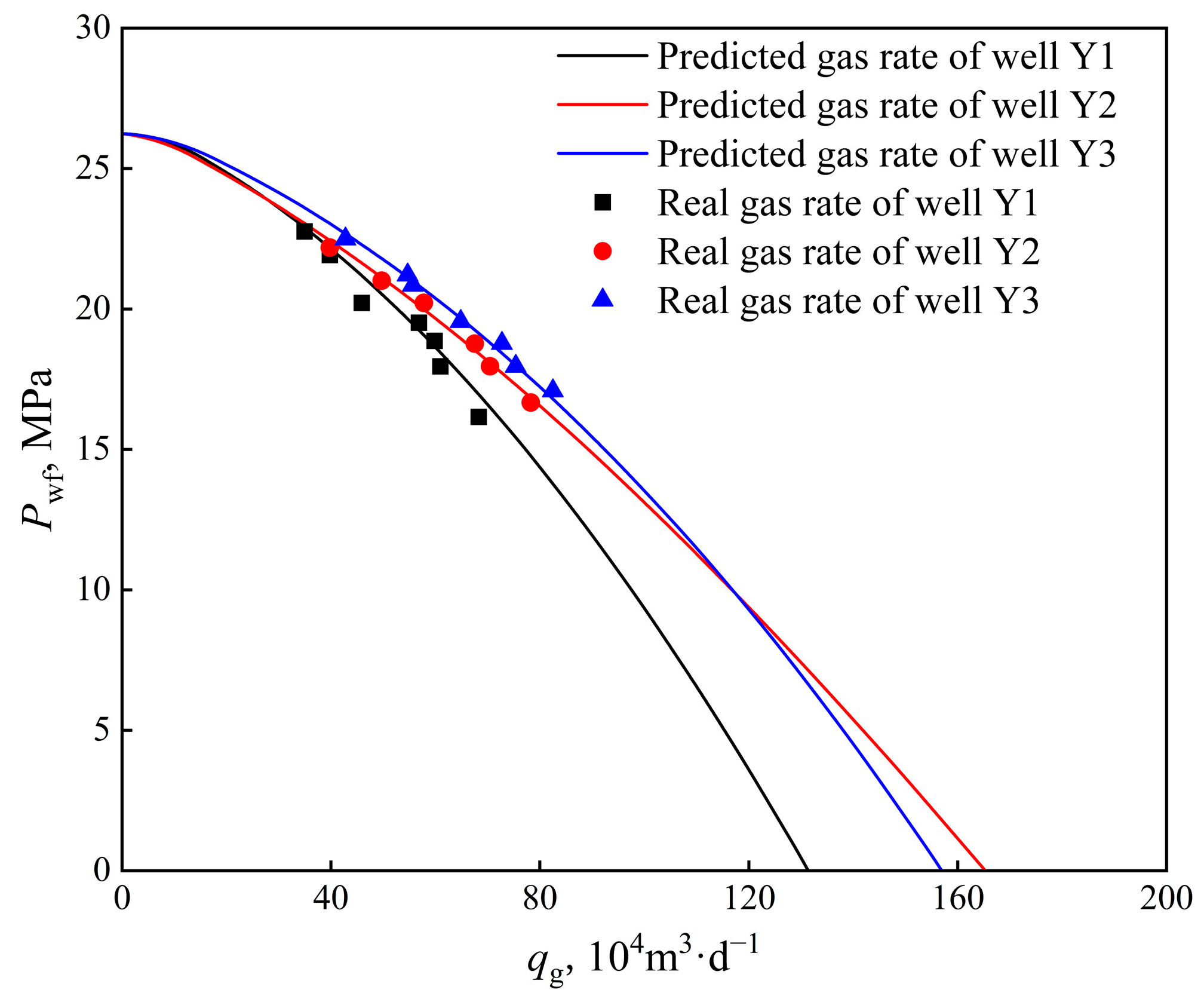
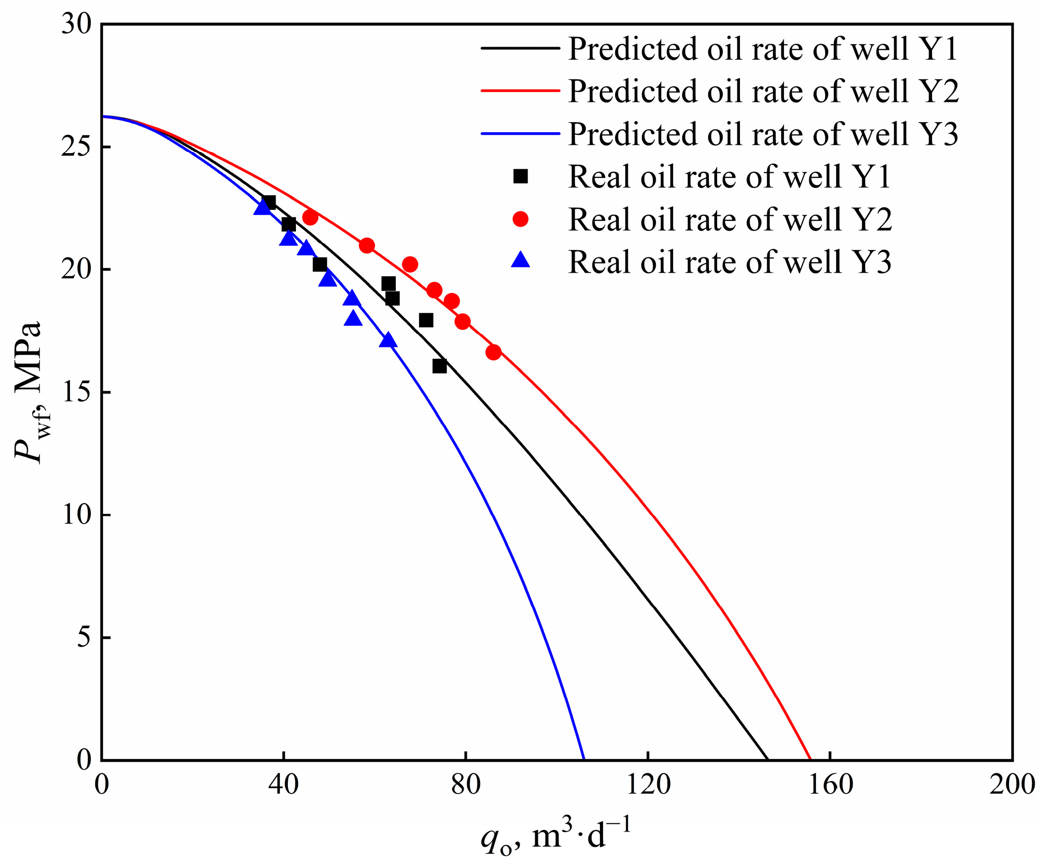
According to the three-phase productivity equation, the equivalent total flow of the gas wells is solved. The gas well production under different pressures can be obtained according to the saturation relationship of oil, gas, and water. The inflow performance curve of the water-bearing condensate gas reservoir is shown in Figure 5, Figure 6 and Figure 7. The figures show that the output calculated by the proposed model can better fit the actual production data.
In order to quantitatively describe the difference between the predicted rate calculated by the model proposed in this paper and the actual rate, the average error between the three horizontal wells is calculated. The error is calculated using the following equation:
E r r o r = i = 1 n ( q i q i 0 ) / q i 0 n
where qi is the phase rate predicted by the proposed model, qi0 is the real rate of the horizontal wells, n is the number of test points.
Figure 8 shows the average error between the rate predicted by the proposed model and the real rate of the three horizontal wells. It shows that except for the gas production error of Well Y3, the average error of the production data of the other gas wells is below 4%. The fitting effect of Well Y2 is better than that of the other two horizontal wells, and the average error of the oil, gas, and water phases is below 3%. The accuracy of the model is verified by example verification and error analysis.
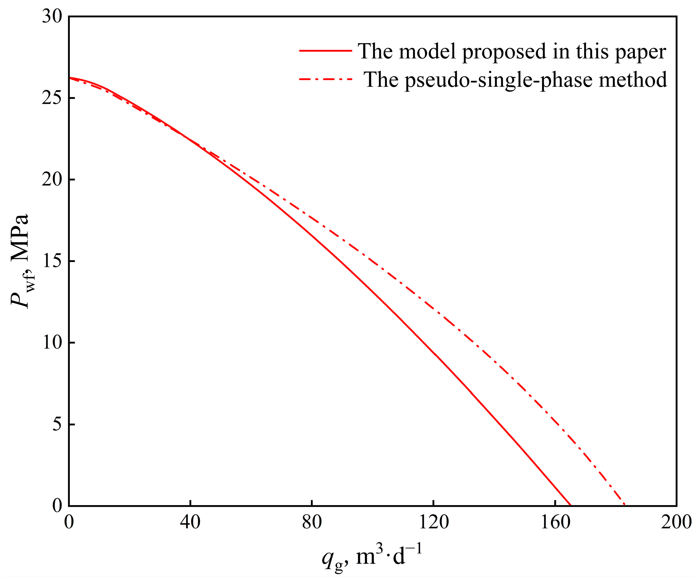
Zhang H et al. proposed a pseudo-single-phase method for calculating the condensate gas productivity, and converted the condensate fluid volume at the wellhead into the corresponding condensate gas volume [39]. The model proposed in this paper is compared with it, as shown in Figure 9. When the production pressure difference is small, the productivity of the two methods is close. When the production pressure difference is large, the calculation results of the two methods are quite different. This is because the pressure difference increases and the condensate oil content increases. At the same time, the quasi-single-phase method does not consider the influence of the non-Darcy effect. Compared with the pseudo-single-phase method, the three-phase flow energy equation proposed in this paper can more accurately calculate the productivity of horizontal wells in condensate gas reservoirs.

5. Conclusions

(1)
In this paper, a three-phase productivity calculation model for horizontal wells in water-bearing condensate gas reservoirs is proposed, which considers the non-Darcy effect. The total pseudopressure and the equivalent total flow are defined to solve the multiphase nonlinear problem in the oil–gas–water three-phase control flow equation, and to establish a three-phase productivity equation.
(2)
The key to the productivity model proposed in this paper is to solve the total pseudopressure. Based on the relationship between the saturation and pressure, combined with the relative permeability curve, the relationship between the saturation and pressure is established, and the total pseudopressure function is solved using the numerical integration method. Combined with the equivalent total flow, the productivity equation is determined by regression.
(3)
The field cases and error analysis of three horizontal wells in a condensate gas reservoir show that the proposed model can fit the actual production data better. The results show that except for the gas production error of Well Y3, the average error of the production data of the other gas wells is below 4%. The fitting effect of Well Y2 is better than that of the other two horizontal wells, and the average error of the oil, gas, and water phases is below 3%.
(4)
The pseudo-single-phase method has a large error when the pressure difference is large, and the three-phase flow production equation proposed in this paper can more accurately calculate the production capacity of horizontal wells in condensate reservoirs.

Author Contributions

Conceptualization, A.X.; Methodology, A.X. and E.L.; Software, J.H.; Validation, J.H.; Investigation, X.Z.; Data curation, Y.L.; Writing—original draft, Y.Z.; Writing—review & editing, Y.C. and L.J. All authors have read and agreed to the published version of the manuscript.

Funding

This research received no external funding.

Data Availability Statement

The data presented in this study are available on request from the corresponding author. The data are not publicly available due to privacy.

Conflicts of Interest

All authors were employed by the company PetroChina Research Institute of Petroleum Exploration and Development. They declare that the research was conducted in the absence of any commercial or financial relationships that could be construed as a potential conflict of interest.

References

  1. Behmanesh, H.; Mattar, L.; Thompson, J.M.; Anderson, D.M.; Nakaska, D.W.; Clarkson, C.R. Treatment of Rate-Transient Analysis During Boundary-Dominated Flow. SPE J. 2018, 23, 1145–1165. [Google Scholar] [CrossRef]
  2. Ghahri, P.; Jamiolahmady, M.; Sohrabi, M. Gas condensate flow around deviated and horizontal wells. In Proceedings of the SPE Europec featured at EAGE Conference and Exhibition, Vienna, Austria, 23–27 May 2011. [Google Scholar]
  3. Abad, A.R.B.; Mousavi, S.; Mohamadian, N.; Wood, D.A.; Ghorbani, H.; Davoodi, S.; Alvar, M.A.; Shahbazi, K. Hybrid machine learning algorithms to predict condensate viscosity in the near wellbore regions of gas condensate reservoirs. J. Nat. Gas Sci. Eng. 2021, 95, 104210. [Google Scholar] [CrossRef]
  4. Afidick, D.; Kaczorowski, N.J.; Bette, S. Production performance of a retrograde gas reservoir: A case study of the Arun field. In Proceedings of the SPE Asia Pacific Oil and Gas Conference and Exhibition, Melbourne, Australia, 7–10 November 1994; SPE: Richardson, TX, USA, 1994; p. SPE-28749. [Google Scholar]
  5. Zhang, W.; Cui, Y.; Jiang, R.; Xu, J.; Qiao, X.; Jiang, Y.; Zhang, H.; Wang, X. Production performance analysis for horizontal wells in gas condensate reservoir using three-region model. J. Nat. Gas Sci. Eng. 2019, 61, 226–236. [Google Scholar] [CrossRef]
  6. Jun, J.; Kang, J.; Jeong, D.; Lee, H. An efficient approach for optimizing full field development plan using Monte-Carlo simulation coupled with genetic algorithm and new variable setting method for well placement applied to gas condensate field in Vietnam. Energy Explor. Exploit. 2017, 35, 75–102. [Google Scholar] [CrossRef]
  7. Saleh, A.M.; Stewart, G. Interpretation of gas condensate well tests with field examples. In Proceedings of the SPE Annual Technical Conference and Exhibition, Washington, DC, USA, 4–7 October 1992; SPE: Richardson, TX, USA, 1992; p. SPE-24719. [Google Scholar]
  8. Daungkaew, S.; Ross, F.; Gringarten, A.C. Well test analysis of condensate drop-out behavior in a North Sea len gas condensate reservoir. In Proceedings of the SPE Annual Technical Conference and Exhibition, San Antonio, TX, USA, 29 September–2 October 2002; p. 77548. [Google Scholar]
  9. Marhaendrajana, T.; Kaczorowski, N.J.; Blasingame, T.A. Analysis and interpretation of well test performance at Arun field, Indonesia. In Proceedings of the SPE Annual Technical Conference and Exhibition, Houston, TX, USA, 3–6 October 1999; SPE: Richardson, TX, USA, 1999; p. SPE-56487. [Google Scholar]
  10. Bonyadi, M.; Rahimpour, M.R.; Esmaeilzadeh, F. A new fast technique for calculation of gas condensate well productivity by using pseudopressure method. J. Nat. Gas Sci. Eng. 2012, 4, 35–43. [Google Scholar] [CrossRef]
  11. Dahim, S.; Taghavinejad, A.; Razghandi, M.; Rigi, H.R.; Moeini, K.; Jamshidi, S.; Sharifi, M. Pressure and rate transient modeling of multi fractured horizontal wells in shale gas condensate reservoirs. J. Pet. Sci. Eng. 2020, 185, 106566. [Google Scholar] [CrossRef]
  12. Gringarten, A.C.; Al-Lamki, A.; Daungkaew, S.; Mott, R.; Whittle, T.M. Well test analysis in gas-condensate reservoirs. In Proceedings of the SPE Annual Technical Conference and Exhibition, Dallas, TX, USA, 1–4 October 2000. [Google Scholar]
  13. Fussell, D.D. Single-well performance predictions for gas condensate reservoirs. J. Pet. Technol. 1973, 25, 860–870. [Google Scholar] [CrossRef]
  14. Yin, F.; Cheng, S.; Liu, X.; Zhang, L.; Liu, H.; Bai, W.; Shi, D.; Wang, Y. Semianalytical Modeling for Multiphase Flow in a Fractured Low-Permeability Gas Condensate Reservoir. ACS Omega 2023, 8, 32892–32906. [Google Scholar] [CrossRef] [PubMed]
  15. Shaoul, J.R.; Park, J.; Boucher, A.; Tkachuk, I.; Veeken, C.; Salmi, S.; Bahri, K.; Rashdi, M.; Nazaruk, D. Evaluating the Performance of Horizontal Multi-Frac Wells in a Depleted Gas Condensate Reservoir in Sultanate of Oman. In Proceedings of the SPE International Hydraulic Fracturing Technology Conference and Exhibition, Muscat, Oman, 11–13 January 2022; SPE: Richardson, TX, USA, 2022; p. D031S013R004. [Google Scholar]
  16. Daneshfar, R.; Keivanimehr, F.; Mohammadi-Khanaposhtani, M.; Baghban, A. A neural computing strategy to estimate dew-point pressure of gas condensate reservoirs. Pet. Sci. Technol. 2020, 38, 706–712. [Google Scholar] [CrossRef]
  17. Bai, W.; Cheng, S.; Wang, Y.; Cai, D.; Guo, X.; Guo, Q. A transient production prediction method for tight condensate gas wells with multiphase flow. Pet. Explor. Dev. 2024, 51, 1–7. [Google Scholar] [CrossRef]
  18. Dehane, A.; Tiab, D.; Osisanya, S.O. Comparison of the performance of vertical and horizontal wells in gas-condensate reservoirs. In Proceedings of the SPE Annual Technical Conference and Exhibition, Dallas, TX, USA, 1–4 October 2000; SPE: Richardson, TX, USA, 2000; p. SPE-63164. [Google Scholar]
  19. Ertekin, T. Neuro-simulation analysis of pressure maintenance operations in gas condensate reservoirs. J. Pet. Sci. Eng. 2007, 58, 207–226. [Google Scholar]
  20. Kniazeff, V.J.; Naville, S.A. Two-phase flow of volatile hydrocarbons. Soc. Pet. Eng. J. 1965, 5, 37–44. [Google Scholar] [CrossRef]
  21. Mokhtari, R.; Varzandeh, F.; Rahimpour, M.R. Well productivity in an Iranian gas-condensate reservoir: A case study. J. Nat. Gas Sci. Eng. 2013, 14, 66–76. [Google Scholar] [CrossRef]
  22. Mott, R. Engineering calculations of gas-condensate-well productivity. SPE Reserv. Eval. Eng. 2003, 6, 298–306. [Google Scholar] [CrossRef]
  23. Muladi, A.; Pinczewski, W.V. Application of horizontal well in heterogeneity gas condensate reservoir. In Proceedings of the SPE Asia Pacific Oil and Gas Conference and Exhibition, Jakarta, Indonesia, 20–22 April 1999; SPE: Richardson, TX, USA, 1999; p. SPE-54351. [Google Scholar]
  24. Behmanesh, H.; Hamdi, H.; Clarkson, C.R. Production data analysis of tight gas condensate reservoirs. J. Nat. Gas Sci. Eng. 2015, 22, 22–34. [Google Scholar] [CrossRef]
  25. Wang, Y.; Xie, H.; Gao, Y.; Feng, N.; Yu, H. Evaluation of Liquid Production and Water Injection Profiles of Horizontal Well by Pressure-Transient Analysis: Field Cases. Energy Fuels 2023, 37, 18890–18898. [Google Scholar] [CrossRef]
  26. Stewart, G. Wireline Formation Testing and Well Deliverability; PennWell: Tulsa, OK, USA, 2012. [Google Scholar]
  27. Zhang, H.; Lu, J.; Cao, W.; Sun, H. Usual productivity equation of gas well on various units of measurement. Well Test. 2017, 26, 1–7. [Google Scholar]
  28. Muskat, M. Some theoretical aspect s of cycling–Part 2: Retrograde condensation about well bores. Oil Gas J. 1950, 48, 53–55. [Google Scholar]
  29. Thompson, L.G.; Niu, J.G.; Reynoalds, A.C. Well testing for gas condensate reservoirs. In Proceedings of the SPE Asia Pacific Oil and Gas Conference, Singapore, 8–10 February 1993; p. SPE-25371. [Google Scholar]
  30. Liu, X.; Chen, H.; Chen, Z.; Yang, R.; Song, L.; Bai, M.; Qiu, P.; Zuo, M.; Li, B.; Yang, B.; et al. Study on characterization and distribution of four regions of tight sandstone condensate gas reservoirs in the depletion development process. Fuel 2024, 358, 130267. [Google Scholar] [CrossRef]
  31. Ghahri, P.; Jamiolahmadi, M.; Alatefi, E.; Wilkinson, D.; Sedighi Dehkordi, F.; Hamidi, H. A new and simple model for the prediction of horizontal well productivity in gas condensate reservoirs. Fuel 2018, 223, 431–450. [Google Scholar] [CrossRef]
  32. Zhao, H.; Zhang, X.; Gao, X.; Chen, P.; Guo, K. A Novel Method for the Quantitative Evaluation of Retrograde Condensate Pollution in Condensate Gas Reservoirs. Processes 2024, 12, 522. [Google Scholar] [CrossRef]
  33. Walsh, M.; Lake, L.W. A Generalized Approach to Primary Hydrocarbon Recovery; Elsevier: Amsterdam, The Netherlands, 2003. [Google Scholar]
  34. Lal, R.R. Well Testing in Gas-Condensate Reservoirs. Master’s Thesis, Department of Petroleum Engineering of Stanford University, Stanford, CA, USA, 2003. [Google Scholar]
  35. Zhou, C.; Wu, X.; Li, H.; Lin, H.; Liu, X.; Cao, M. Optimization of methods for liquid loading prediction in deep condensate gas wells. J. Pet. Sci. Eng. 2016, 146, 71–80. [Google Scholar] [CrossRef]
  36. Li, J.; Zhao, G.; Jia, X.; Yuan, W. Integrated study of gas condensate reservoir characterization through pressure transient analysis. J. Nat. Gas Sci. Eng. 2017, 46, 160–171. [Google Scholar] [CrossRef]
  37. Liu, H.; Xie, B.; Xin, X.; Zhao, H.; Liu, Y. Investigation on the Extent of Retrograde Condensation of Qianshao Gas Condensate Reservoir Using PVT Experiments and Compositional Reservoir Simulation. Processes 2024, 12, 503. [Google Scholar] [CrossRef]
  38. Zhang, L.; Yin, F.; Liang, B.; Cheng, S.; Wang, Y. Pressure Transient Analysis for the Fractured Gas Condensate Reservoir. Energies 2022, 15, 9442. [Google Scholar] [CrossRef]
  39. Fevang, O.; Whitson, C.H. Modeling gas-condensate well deliverability. SPE Reserv. Eng. 1996, 11, 221–230. [Google Scholar] [CrossRef]
Figure 1. The production scenario of horizontal well in gas condensate reservoir.
Energies 17 02932 g001
Figure 2. Flowchart of three-phase productivity model of condensate gas reservoir.
Energies 17 02932 g002
Figure 3. Relative permeability of gas reservoir.
Energies 17 02932 g003
Figure 4. Relationship between ΨeΨw/qe and qe.
Energies 17 02932 g004
Figure 5. Inflow dynamic curve of gas.
Energies 17 02932 g005
Figure 6. Inflow dynamic curve of oil.
Energies 17 02932 g006
Figure 7. Inflow dynamic curve of water.
Energies 17 02932 g007
Figure 8. The rate error between predicted model and real date.
Energies 17 02932 g008
Figure 9. Comparison of gas IPR curves in well Y2 obtained with two methods.
Energies 17 02932 g009
Table 1. The basic parameters of reservoir and horizontal well.
ParameterValue
Original reservoir pressure Pe (MPa)26.2
Reservoir thickness h (m)8.54
Reservoir porosity Φ0.16
Original formation permeability ki (10−3 μm2)39.7
Reservoir temperature T (K)346
Gas density under standard conditions ρgsc (kg/m3)0.76
Oil density under standard conditions ρosc (kg/m3)728
Disclaimer/Publisher’s Note: The statements, opinions and data contained in all publications are solely those of the individual author(s) and contributor(s) and not of MDPI and/or the editor(s). MDPI and/or the editor(s) disclaim responsibility for any injury to people or property resulting from any ideas, methods, instructions or products referred to in the content.