Article

The Influence of Reservoir Architecture on the Connectivity of the Shahejie Formation in the Liuzhong Oilfield

1
China National Petroleum Corporation, Jidong Oilfield, Tangshan 063000, China
2
College of Geosciences, China University of Petroleum-Beijing, Beijing 102249, China
*
Author to whom correspondence should be addressed.
Energies 2024, 17(1), 115; https://doi.org/10.3390/en17010115
Submission received: 23 November 2023 / Revised: 20 December 2023 / Accepted: 22 December 2023 / Published: 24 December 2023

Abstract

:
The lack of research on fine reservoir structure and sand body patterns in the Jidong Oilfield currently restricts the efficient development of the oilfield. Therefore, this article mainly focuses on the study of the main types of facies of the Shahejie Formation, sand body splicing patterns, and the degree of sand-body connectivity. The interpretation and analysis of well-logging, three-dimensional (3D) seismic, and production data were used to lay the foundation for the study and evaluate the remaining oil distribution. The results indicate that the reservoir sandstones in the study area were mainly deposited in a submerged distributary channel, mouth bar, and distributary channel flank. Using logging information to identify individual sands, a deltaic sand assemblage pattern is proposed by analyzing the sedimentary architecture. In the vertical direction, the deltaic sand body collocation style can be divided into cut-and-stack and separated types. In the lateral direction, the multi-stage sand bodies exhibit three collocation patterns: the side-cutting type, the mouth bar contact type, and the submerged distributary channel flank contact type. The degree of sand-body connectivity under different splicing patterns was analyzed and verified using production dynamic data. It was found that the sand body splicing pattern with a vertical up-cut stack and the sand body splicing pattern with a lateral up-cut had the best inter-sand-body connectivity.

1. Introduction

Deltaic sedimentary reservoirs are the most dominant types in China’s terrestrial oil- and gas-bearing basins. They account for 54% of the developed petroleum fields [1,2,3]. These reservoirs have been developed and produced over many years but still contain between 16.6% and 36.6% of the remaining movable oil. In contrast, the deltaic foreland sandstones are small in size and fast in facies change. The type of single sand body development, single sand body superposition relationship, and connectivity of the deltaic foreland are poorly understood. The lack of fine reservoir architecture and sand body pattern interpretation restricts efficient oil field development [4,5,6].
Reservoir architecture refers to different reservoir units’ shape, scale, direction, and superposition relationships [7]. Research on reservoir architecture is critical to oil field development, especially in finding remaining oil in near-field exploration and improving oil recovery. Integrating seismic, logging, and core data combined with modern sedimentary outcrop profiles is the main approach used to study the sand bodies of the deltaic foreshore. Nevertheless, the sand connectivity between the wells in the study area is complex, and the actual production needs can no longer be met by logging and seismic data alone. It is necessary to combine actual production dynamics data to compensate for the poor prediction accuracy of inter-well sand bodies and enhance the study of inter-well residual oil enrichment areas [8,9,10,11,12].
The study of sand-body connectivity is of great significance for characterizing reservoir heterogeneity [13,14], reservoir simulation [15], and predicting the distribution of remaining oil [16]. There are various methods for studying sand-body connectivity, such as using inter-well stratigraphic correlation and tracer tracking to investigate sand-body connectivity [17,18] and utilizing seismic reflection amplitude characteristics to study the internal connectivity of reservoirs [19,20]. Hu Zongquan (2003) evaluated sand-body connectivity through single-well statistical analysis, multi-well inter-well log interpolation, and sand-body comparison methods [21]. Wen Zhigang (2004) applied a chromatographic fingerprinting technique to study the fluid connectivity between inter-well layers [22]. Liu Chuanqi (2008) studied the connectivity of sand bodies in the Bohai A Oilfield through logging information, multi-seismic attribute clustering analysis, and other methods [23]. Lei Yuhong (2013) determined the connectivity of sand bodies using production dynamic data and combined analysis of crude oil full hydrocarbon gas-phase chromatographic fingerprinting characteristics [24]. Wang Haigeng (2014) comprehensively analyzed the connectivity of sand bodies using seismic data and introduced the concept of the injection–production connectivity rate to quantitatively describe sand-body connectivity [25]. However, the aforementioned methods also have limitations. For instance, studying the connectivity of sand bodies using tracer tests requires the appropriate selection of tracers and injection methods, which may be constrained by geological conditions and environmental factors such as tracer mobility and stability. The tracer tracking method relies on the accurate collection of tracer arrival time data, a process that can be affected by measurement errors and data interpretation, consequently introducing uncertainty into the obtained results. Similarly, studying reservoir connectivity using seismic reflection amplitude characteristics relies heavily on the quality of seismic reflection data. If the data quality is poor or affected by noise interference, it can potentially impact the accurate characterization of reservoir connectivity.
The Shahejie Formation in the Liuzhong Oilfield of the Nanpu Depression, China is characterized by a large thickness (1350 m) and rapid lateral and vertical changes. There are a few contrasting marker layers. Multiple phase faults intersect each other due to complex tectonics. The sand bodies represent small-scale fan delta (single layer thickness 2–7 m) and rapid facie changes. The reservoir distribution is influenced by multiple phases of reservoir formation and oil and gas enrichment patterns are complex with large differences between the planar and vertical distribution. In addition, the oil–water system is complex, with no unified oil–water interface. After years of development, the reservoir has entered an extraordinarily high water production stage. The remaining oil enrichment area of the complex fault block reservoir is unknown. The sand connectivity between the wells is unknown, and the control mechanism of sand distribution on the remaining oil distribution needs to be urgently identified [26,27,28,29].
Therefore, reservoir architecture and connectivity analysis are essential. In this study, an integrated inter-well analysis method was used to combine static and dynamic data. Static geological research was conducted to establish sedimentary facies models, and the distribution characteristics of sedimentary facies were studied by integrating the dynamic data. The analysis of the contact relationships of architecture units in both the vertical and planar directions was carried out. Based on dynamic production data, the connectivity analysis of sand bodies was conducted to validate the correctness of the static geological research.

2. Geological Overview

The Liuzhong Oilfield is located in the Liuzan Oilfield in the Caofeidian District, Tangshan City, Hebei Province, China, and it is one of the three main development areas of the Liuzan Oilfield. The Liuzhong Oilfield occupies approximately 90 km2, and it is located in the Liuzan tectonic zone in the northeastern part of the Nanbu Depression, connected to the Shichang Depression to the north, bounded by the Baigezhuang Fault to the east and adjacent to the Gao Shangbao formation to the west (Figure 1). The main body of the Shahejie Formation in the Liuzhong Oilfield is a condiment anticline divided by normal faults. The area is intersected by 16 main developed normal faults with northeast and northwest orientations. The currently developed oil and gas reservoirs are mainly the Liu 1, Liu 90 South, Liu 90 North, Liu 28-1, Liu 2, and Liu 18 fault blocks, a total of six fault blocks [30,31,32,33,34,35,36] (Figure 1).
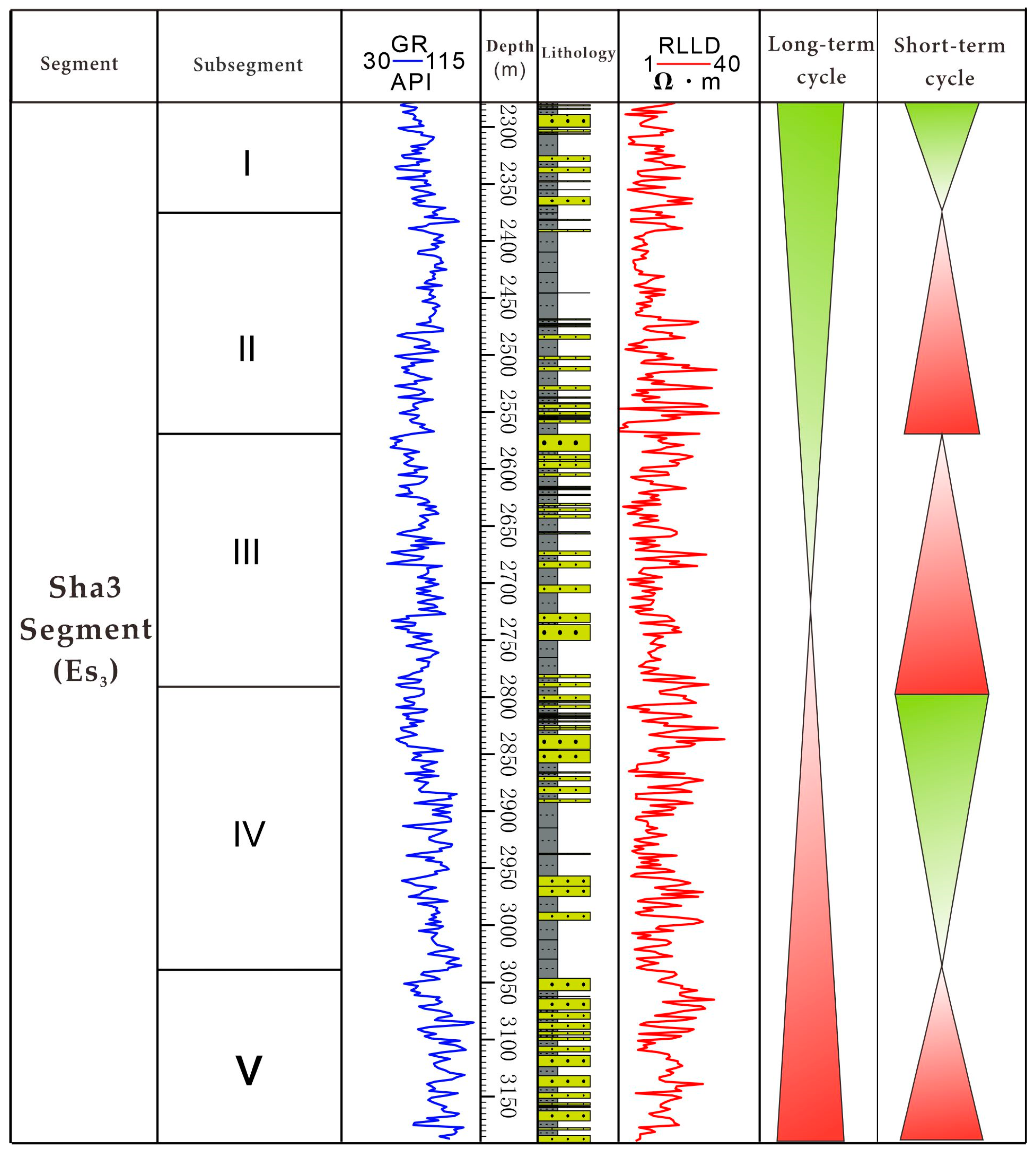
The stratigraphy of the Liuzhong Oilfield is relatively well understood, with thick layers of Middle and Cenozoic strata developing above the crystalline base of the Archaean. The Paleoproterozoic is the period of rift development in the Nanbu Depression. The Shahejie Formation is the thickest stratigraphic unit. The Shahejie Formation and the Dongying Formation are both disconformities. The Shahejie Formation is about 42 million years old. The area is located in the subduction zone of the Baigezhuang orthotropic fault. It had a sufficient sedimentary material supply from the northeast-trending Ma Touying Bulge and developed a near-sourced lacustrine fan-deltaic sedimentary system. The Shahejie Formation can be divided into three segments, with the sedimentary thickness of the Sha3 segment being about 1200 m, which can be subdivided into five subsegments. The Sha3 Formation and the Sha2 Formation are disconformities. The sedimentary rocks of the Sha3 Formation mainly consist of gravelly sandstone, dark, gray, red mudstone, and Grayish-black mud, interbedded with thin sandstone and oil shale (Figure 2).

3. Materials and Methods

The data used in this study include well-log curves, stratigraphic data, and core and experimental assay data from 243 wells in the Liuzhong Oilfield. Well-log curves from 243 wells, including the gamma-ray log curves (GR) and deep investigate double lateral resist (RLLD) and spontaneous potential log curves (SP), were used in our analysis. In addition, suction fluid data from 15 wells, monitoring data from three tracer well sets, production dynamics data from 61 wells, and basic information such as 3D seismic data covering the whole area were utilized in the study evaluations. According to spectrum analysis, the main frequency of the seismic data of the target layer in the study area was 27 Hz, and the frequency width was 9 to 67 Hz [37]. The facies were initially identified from the core. The base-level cycle was identified and compared using logging data and Integrated Prediction Error Filter Analysis (INPEFA) [38,39,40,41,42,43,44].
This article divides sedimentary microfacies through a combination of seismic, core, and logging methods. Moreover, based on the relationship between the sedimentary characteristics of single-channel sand bodies and logging responses, identification indicators for single sand bodies were established. Based on modern sedimentary models, different types of sand body stacking patterns were summarized, and the connectivity of sand bodies was analyzed and verified using tracers, providing guidance for subsequent development and production.

4. Results

4.1. Sedimentary Phase Classification

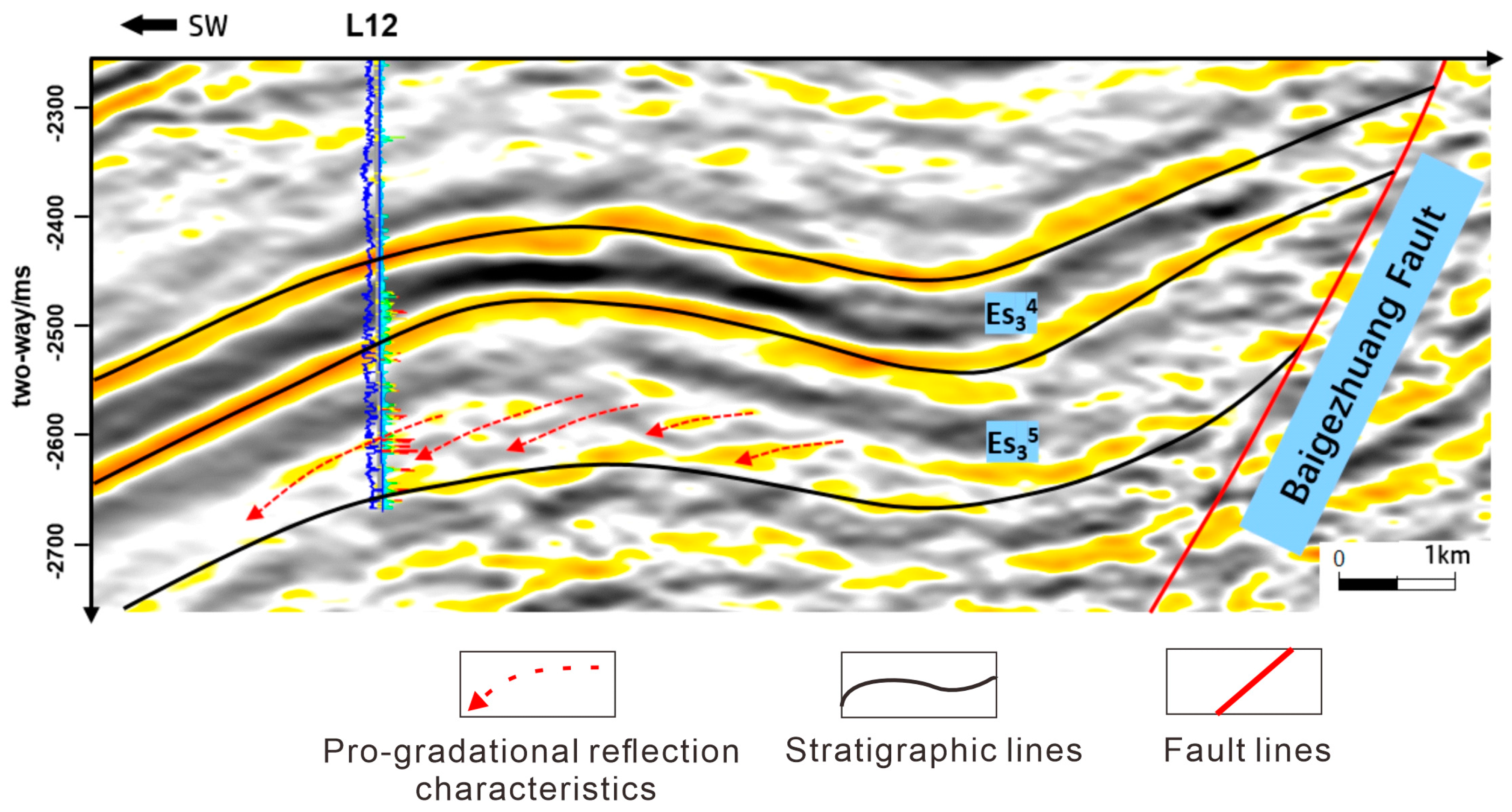
The VI oil group of Es34 subsegments in the study area is well developed in the gray and black mud intercalated oil shale with a distinct seismic response. Using this as a marker layer, the seismic section (Figure 3) provides evidence that there is a distinct foregrounding reflection feature away from the Baigezhuang fault, representing subphase deposition at the front edge of the fan delta.
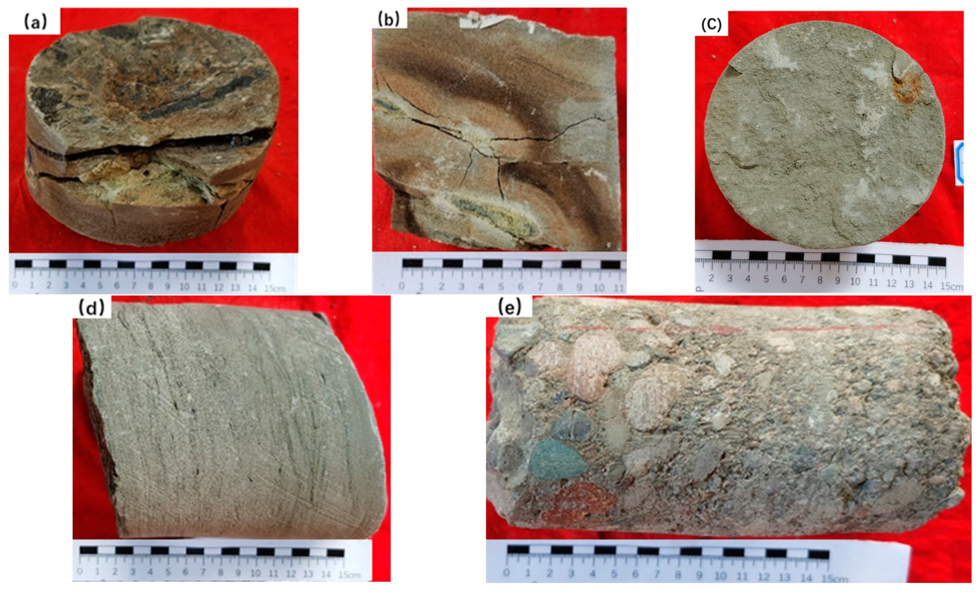
Studying cores from seven conventional coring wells in the Liuzhong Oilfield (Figure 4), with a cumulative core length of 483.3 m, allowed us to identify that the mudstone color was overwhelmingly gray and light green, with more developed charcoal and iron nodules (Figure 4a,b), reflecting an above-water-submerged transitional depositional environment. The top is a pale white medium-to-fine sandstone to gray-green siltstone (Figure 4c). The sedimentary architectures indicate fluvial and wave origin, such as interlocking laminations and scour surface development (Figure 4d). Coarse-grained sediments such as gravels are common at the base (Figure 4e), with poor sorting and moderate rounding.
Integrating various data such as the depositional background, seismic response characteristics, and core observation results allows us to identify that during the Shahejie Formation’s deposition, the Liuzhong Oilfield was the main depositional area of the delta-front surfaces. The delta-front mainly contains three types of sand bodies: distributary channels, mouth bars, and submerged divergent channel flanks. The sedimentary characteristics of the three sand bodies are summarized below.

4.1.1. Distributary Channel Sand Bodies

The sand body of the distributary channel is mainly gravelly sandstone and medium and coarse sandstone. Massive and parallel laminations and scouring architectures are common. Positive rhythms developed vertically, and more uniform rhythms and erosional surfaces are evident at the base. The natural gamma curve appears as a medium-to-high amplitude bell, compound bell, or tooth box (Figure 5a). Distributary channels along the front edge of the delta often diverge in the direction of the sedimentary source, with multiple phases of terminal distributary channel development. Distributary channel sands are dendritic and ribbon-shaped in the map view. The distributary channel sand bodies are larger in size near the source, with thicknesses ranging from 2 to 8 m and an average thickness of 4.2 m.

4.1.2. Mouth Bar Sand Bodies

The mouth bar sand bodies are mainly fine-grained sandstones, commonly blocky laminated, interbedded, and undulating. They show anti-rhythmic or relatively homogeneous complex rhythmic features, with a funnel-shaped natural gamma curve response and common dentition (Figure 5b).

4.1.3. Distributary Channel Flank Sand Bodies

The distributary channel flanks are mainly siltstone and fine-grained sandstone. They are commonly interbedded and parallel laminated, with a low amplitude bell-shaped or finger-shaped natural gamma-ray (GR) curve response, indicating the boundary of the submerged distributary channel, with thin sand bodies, generally less than 3 m (Figure 5c).

4.2. Single Sand Body Identification and Stacking Style

Limited by seismic accuracy, this paper identifies the sedimentary unit interface mainly by applying logging information, establishing single sand body identification markers based on the relationship between the sedimentary characteristics of the single channel sand body and the logging response, and delineating the single sand body in the composite sand body. It is mainly based on the following.
(1)
Differences in elevation
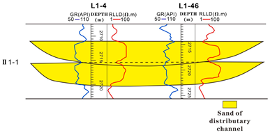
Sedimentary paleomorphology controls the differences in water bodies’ energies in different submerged distributary channels, which developed at different times. Within the same stratigraphy, there is an elevation difference between the sand bodies of the two channel phases (Figure 6). The single sand bodies of different channels are discerned by the difference in elevation at the top of the sand bodies.
(2)
Differences in microfacies
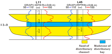
Two submerged distributary channels developed simultaneously, with fine-grained siltstone or mudstone developing between the channels (Figure 7). The fine-grained deposits in the inter-divergent bays are one of the markers that delineate the sand bodies of the different submerged distributary channels.
(3)
Differences in logging curve characteristics
Differences in hydrodynamic conditions and variability characteristics within different submerged distributary channels result in different sedimentation grain sizes and rhythms, manifesting as marked differences in the magnitude or shape of the curves. For example, in II 1-3 (Figure 8), the gamma-ray (GR) curves in Wells L1-25 and L1-12 exhibit a toothed bell pattern. In contrast, the GR curves in Wells L1-37 and L1-26 have a boxy morphology, with no dentition in the curves and a significant return in the middle. Two different channels intersect between Wells L1-12 and L1-37.
(4)
“Thick–thin–thick” pattern of the sand body
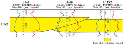
From the center to the edge of the channel, the thickness of the underwater distributary channel sand body gradually decreases. In the same stratigraphic unit, underwater distributary channel sand bodies appear continuously, and the thickness is characterized by a “thick-thin-thick” pattern. There must be a channel boundary between the two channels. In the process of lateral stacking of different watercourses, the logging curve presents a clear reflection, mainly due to the return phenomenon of the natural gamma curve with increased value at the cut stack position (Figure 9).

4.3. Distribution Characteristics of Microfacies in the Whole Area

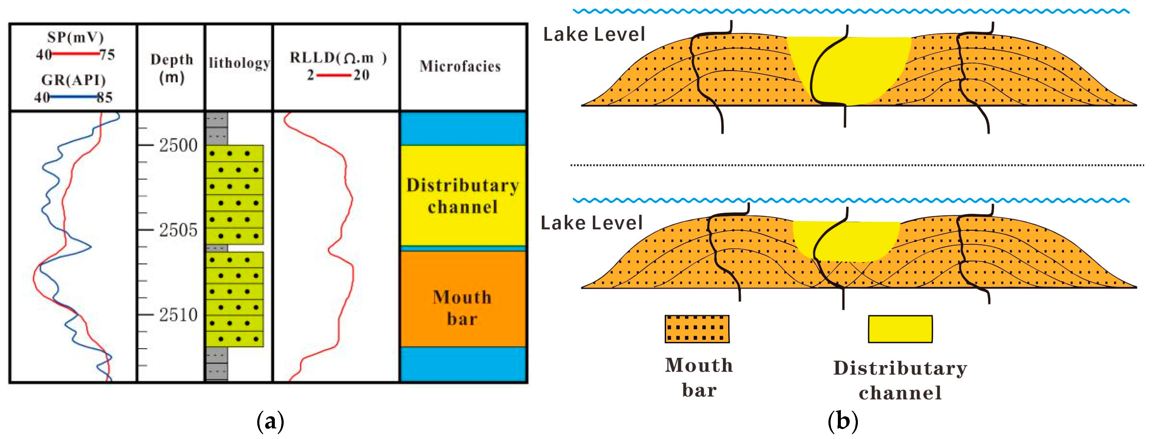
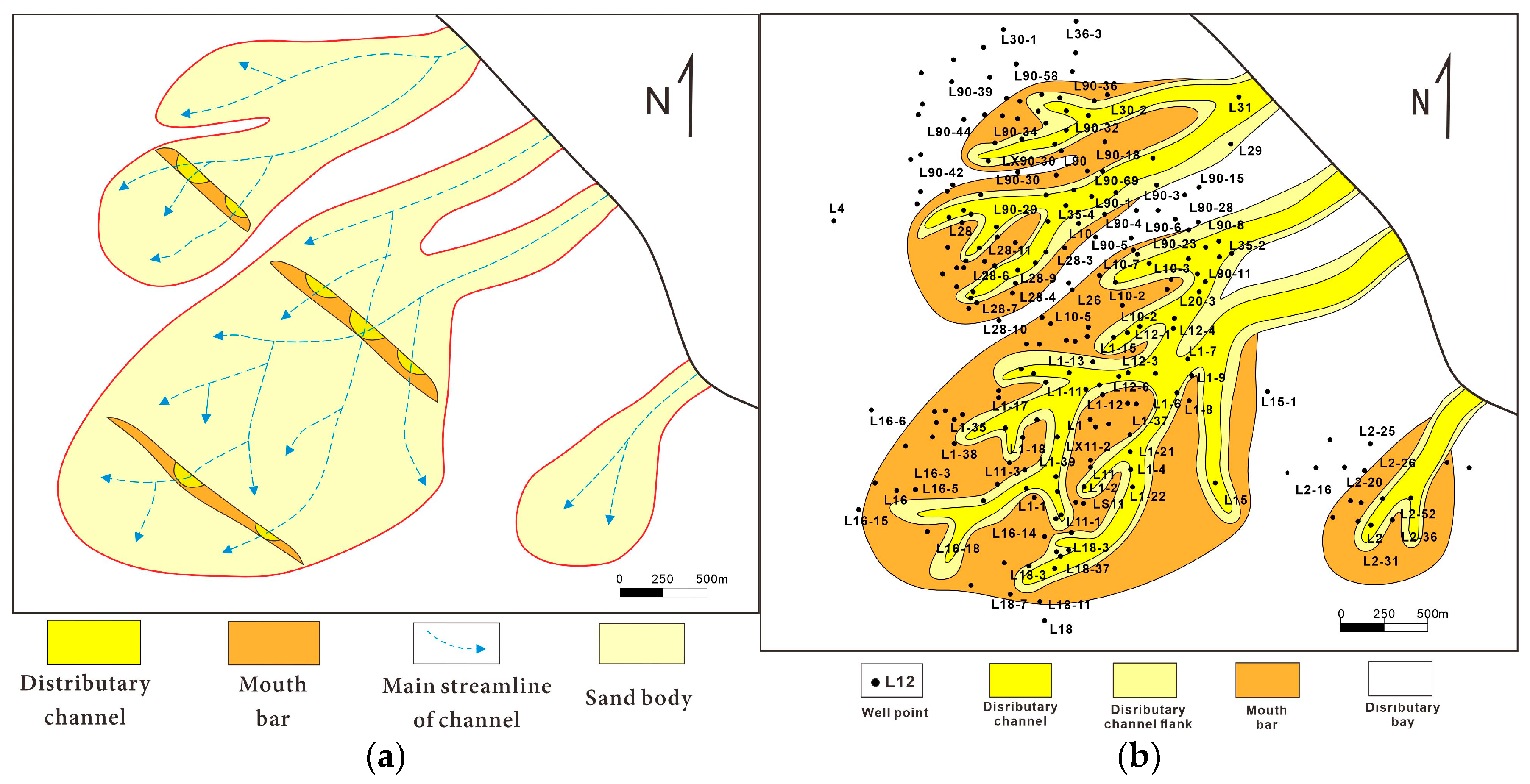
We analyzed the development and combination of microfacies based on the recognition results of single-well microfacies. The results show that the proportion of underwater distributary channels is the highest in the Liuzhong Oilfield, followed by the mouth bars. The typical funnel-shaped curve combination style at the lower part and the bell-shaped curve combination style at the upper part (Figure 10a) reflect the “Upper channel and Lower Bar” mode of “up-front and down-reverse” (Figure 10b).
The sediments of the Shahejie Formation in the Liuzhong Oilfield originate from the northeast Matouying uplift, forming the fan delta-front sand body. Compound banded channel sand body is developed in the near end, GR curve is in positive rhythm. Mouth bars are developed far from the source area, and the curves are mostly in a reverse rhythm or a homogeneous rhythm, with a tongue-like to flower-like distribution (Figure 11). The sand body of the mouth bar is mainly distributed in a large area with a contiguous shape, and it has a drilling rate of more than 30% and a thickness of 4–5 m.
The vertical evolution of the microfacies of the target layer in the whole area mainly shows two types of characteristics (Figure 12). The terrain dip angle was relatively gentle during the sedimentation period of the Es35–Es33 subsegments. The sedimentary water system was far away from the lake basin. The sediments have good gradation and fine septicity of grains.
The drilling rate of the mouth bar is low, averaging 20%, and is distributed on both sides of the channel. The mouth bar shows finger propulsion, such as VIII 2-1 (Figure 13a) and III 3-3 (Figure 13b). During the sedimentation period of the Es35–Es33 subsegments, the terrain was steep, the settlement rate was fast, and the handling distance of debris was short. The sorting property was poor, and the fan size was large. The drilling rate of the mouth bar is high, averaging 40%, which shows blossom distribution, such as II 1-1 (Figure 13a) and I 2-1 (Figure 13b).

5. Discussion

5.1. Sand-Body Connectivity

Frequent channel oscillations and diverse sand stacking styles have formed complex sand-body connectivity relationships [45,46]. In this paper, the connectivity of the sand body is analyzed vertically and laterally, which lays a foundation for evaluating the injection–production relationship of the development’s well pattern and for analyzing the water drive of the reservoir.

5.1.1. Vertical Connectivity of the Sand Body

Vertical connectivity refers to the connection between several adjacent single sand bodies vertically. In the Liuzhong Oilfield, the average content of the filler is 5.5%, the cement content is low, and the cementation is weak. The subaqueous distributary channel is highly hydrodynamic, and the lithology is predominantly coarse-grained gravelly sandstone or massive coarse sandstone.
The connectivity of the tangential superposition sand body is good. The later stage of the channel development completely flushes the fine-grained material from the top of the sand body of the earlier stage channel. The gravelly sandstones with good physical properties at the base of the channel sand bodies are in complete contact vertically, forming interconnected seepage units, with a high degree of vertically connected channel sand bodies in the two cut and stacked phases (Table 1).
Separate sand bodies are not connected. The fine-grained argillaceous sediments in the interdistributary area act as a seepage barrier between the sand bodies, leaving no contact or disconnection between the two single sand bodies (Table 1). Stabilized mud deposits act as a longitudinal barrier separator. Under the combined production and injection method of oil recovery, there are large inter-stratigraphic conflicts due to differences in permeability. The residual oil is easily reached within relatively low permeability layers.

5.1.2. Lateral Connectivity of the Sand Body

Lateral connectivity refers to the connectivity between the adjacent single sand bodies in the plane. The lateral connectivity of a single sand body in contact with different microfacies is different. It affects the displacement path of injected water, thus controlling the remaining oil distribution [47].
Integrating the microfacies’ distribution characteristics with the superimposition style of lateral single sand bodies allowed us to conclude that there are two kinds of lateral contact relationships between adjacent single sand bodies. Two single-channel sand bodies are directly tangent, or the single-channel sand bodies are connected laterally by other microfacies sand bodies. The following two aspects are discussed in detail: the connectivity relationship between different single-channel sand bodies and the relationship between single-channel sand bodies and inter-channel sand bodies.
(1)
Connectivity of different single-channel sand bodies
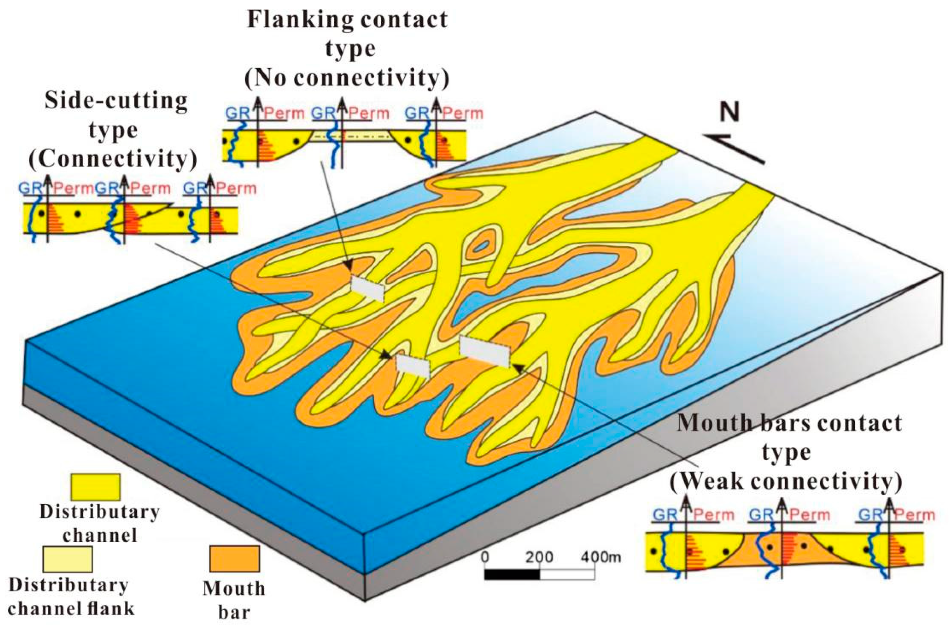
The distributary channel undergoes constant bifurcation, crossings, and diversions as it moves forward, often with the superposition of another single-channel sand body. Different single-channel sand bodies are in direct contact on the plane, and the overlap pattern of a single sand body is of the side-cutting type.
The lithology of underwater distributary channels is mainly sandy conglomerate, gravelly sandstone, and sandstone. The underwater distributary channel is shown as a “flat top and convex bottom” in the section. When two single-channel sand bodies are directly tangential, it is generally considered that the two single sand bodies are in a connected state (Figure 14, Table 2). The higher the degree of lateral overlap, the better the development of fluid seepage channels and the stronger the connectivity.
(2)
Connectivity of sand body in different microfacies
The sediments of the mouth bars are mainly fine-grained sandstone, often developed with cross-bedding and wavy bedding. The permeability of these sediments is low. When mouth bar sand bodies develop between two single-channel sand bodies, it usually indicates weak connectivity (Figure 14 and Table 2).

5.2. Production Dynamic Verification of Connectivity

Production dynamics information can effectively verify sand connectivity between wells. Tracer test data were used to verify the accuracy of our observations on the connectivity of different sand stacking patterns between the wells in the study area by comparing and analyzing the degree of tracer effectiveness of the good groups.

5.2.1. Well Group Tracer Effectiveness Analysis

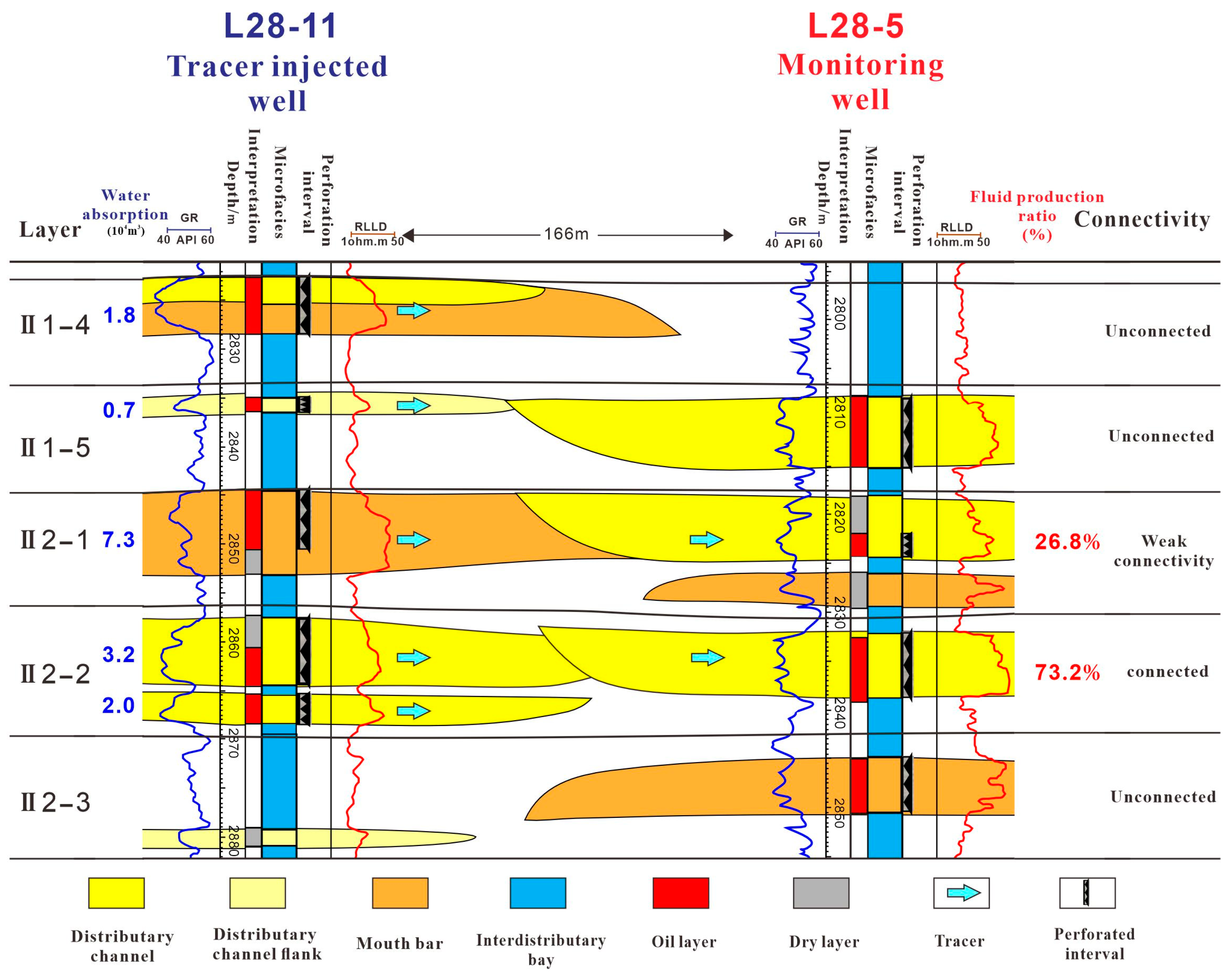
This paper analyzes the effectiveness of the tracer in the good group using the II 1-4 to II 2-3 substrate of Well L28-11 and Well L28-5 injection and extraction well pairs as an example (Figure 15).
The II 1-5 layer is a submerged distributary channel sand body contacting the side-wing sand body. Well L28-11 has an accumulated water absorption of 0.7 × 10⁴ m3, i.e., low water absorption.
The II 2-1 layer is the contact between the submerged distributary channel sand body and the mouth bar sand body. Well L28-11 has an accumulated water absorption of 7.3 × 10⁴ m3, and Well Liu28-5 has a 26.8% liquid yield. The tracer is effective, and the sand bodies between the wells are in a weak state of connectivity.
There are two single sand bodies in the II2-2 layer. The lower sand body is pinching out of the estuary bar sand body, and the upper sand body is a side-cut superimposed pattern of the underwater distributary channel sand body.
Well L28-11 has an accumulated water absorption of 3.2 × 10⁴ m3, and Well L28-5 has a 73.2% liquid yield. The tracer is effective, which proves that the sand bodies between the wells are connected.
The II 2-3 layer is the sand body of the mouth bar and the sand body of the channel flank in different periods. An insufficient tracer proves that no contact occurs between the sand bodies, and the inter-well sand bodies are not connected.
Comprehensive analysis shows that the two peak times of the tracer occur in the II 2-2 and II 2-1 layers (Table 3). The II 2-2 layer has good inter-well connectivity, high water absorption, and a high liquid production ratio. The water drive speed of the tracer is faster than that of the II 2-1 layer.

5.2.2. Dynamic Verification of Sand Body Overlay Style and Connectivity

Based on well group tracer analysis, the relationship between overlapping patterns and connectivity of sand bodies is verified by overlapping microfacies map of small layer sediments. The effectiveness of the tracer indicates that the sand bodies between wells are connected [48,49,50,51,52,53,54,55].
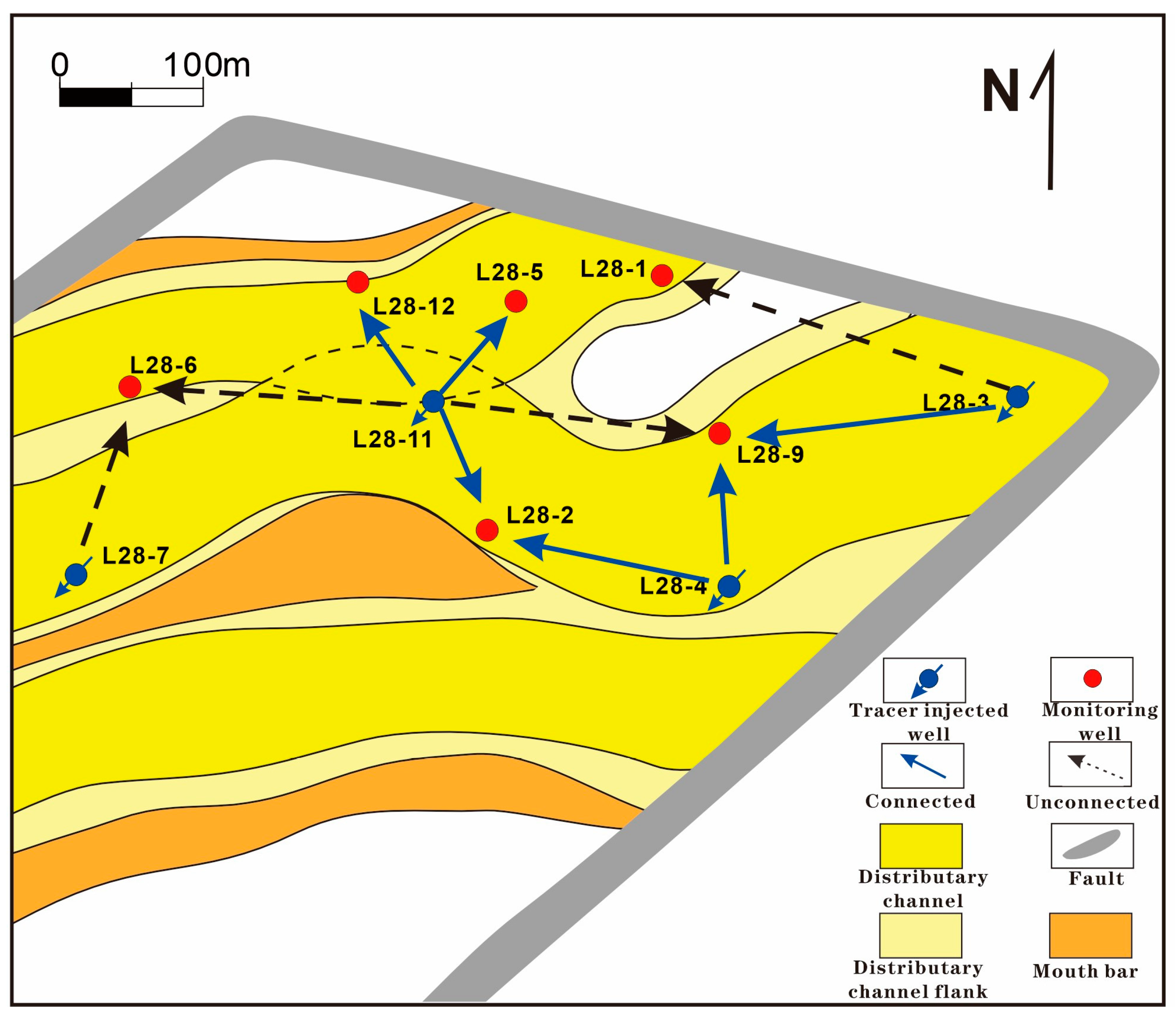
Taking layer II 2-2 as an example (Figure 16), there are four tracer well groups in this layer. Comprehensive analysis shows the following.
The injection wells in the same channel are connected with the monitoring wells, such as Well L28-3 and Well L28-9, Well L28-4 and Well L28-2, and Well L28-11 and Well L28-2. The tracer effectiveness between injection and monitoring wells shows that the sand bodies between the wells are not connected for the injection–production well pairs in different channels separated by sand bodies at the edge of the underwater distributary channel. Examples include Well Liu28-11 and Well Liu28-6, and Well Liu28-11 and Well Liu28-9.
The distributary bay mudstone is developed between Well L28-3 and Well L28-1. Hence, the sand bodies are not in contact with each other. There is no fluid connection between the wells.
The present study has certain limitations in the analysis of sand-body connectivity using tracers, based on architecture analysis. For instance, the tracer tracking method may encounter issues such as dispersion, degradation, or adsorption of tracers in the subsurface environment, resulting in the uneven distribution of the tracers, potentially affecting the accurate assessment of sand-body connectivity. Furthermore, the tracer tracking method necessitates the accurate collection of tracer arrival time data, a process that can be influenced by measurement errors and data interpretation, thereby introducing uncertainty into the obtained results.
Reservoir connectivity research plays a significant role in oil and gas exploration and development. In the future, with the continuous development of science and technology, research can be conducted in the following aspects: (1) Currently, reservoir connectivity research mainly focuses on the macroscopic scale. In the future, it is anticipated that with the development of nanotechnology and microscopic experiments, research can be further expanded to smaller scales. This will contribute to a better understanding of reservoir pore structure and fluid transport mechanisms; (2) With the development of digital technology, it is expected that more reservoir data will be collected and processed digitally, enabling more accurate reservoir modeling. Digital reservoir modeling can better depict the connectivity characteristics of reservoir sand bodies, which can help optimize oil and gas development and production plans; (3) In the future, reservoir connectivity research can leverage techniques such as artificial intelligence and big data analysis. By processing massive amounts of data and establishing more accurate predictive models, the precision and effectiveness of the research can be further improved. Overall, future reservoir connectivity research will be more refined, digitized, and intelligent, providing more accurate and efficient solutions for oil and gas exploration and development [56,57,58,59,60,61,62,63,64].

6. Conclusions

In this study, the delta sandstone reservoir architecture and connectivity in the Liuzhong Oilfield of the Nanbao Sag were studied using 3D seismic and logging data. The Shahe Street Formation is divided into 10 oil groups, 22 sand groups, and 113 sub-layers. The delta-front reservoir sands in the target section of the study area were mainly deposited in the submerged divergent channel, mouth bar, and distributary channel flanking depositional microphases. Using logging information to identify individual sand bodies, a deltaic sand assemblage pattern was proposed by analyzing depositional formations.
In the vertical direction, the deltaic sand body collocation styles can be divided into cut-and-stack types and separated types. In the lateral direction, the multi-stage sand bodies exhibit three collocation patterns: the side-cutting type, the mouth bar contact type, and the submerged distributary channel flank contact type. In the vertical direction, the tangential stacked sand assemblage pattern has good connectivity. In comparison, the laterally tangential sand assemblage pattern has the best connectivity, followed by the mouth bar contact pattern, and the submerged distributary channel flank contact pattern has the worst connectivity.

Author Contributions

Conceptualization and methodology, T.C. and Y.L.; Investigation, J.C. and L.M.; Data curation, Y.H. and W.Q.; Writing—original draft, T.C., Y.H., L.M. and W.Q.; Writing—review and editing, J.C. All authors have read and agreed to the published version of the manuscript.

Funding

This research received no external funding.

Data Availability Statement

Data are contained within the article.

Conflicts of Interest

Author Tongfeng Cao, Jian Cui and Limin Ma were employed by the China National Petroleum Corp., Jidong Oilfield. The remaining authors declare that the research was conducted in the absence of any commercial or financial relationships that could be construed as a potential conflict of interest.

References

  1. Liao, B.; Xue, Y.; Zhang, M.; Liu, Y.; Wang, Q. New Understandings on Rolling Exploration and Development of Es32+3 Reservoir in Liuzan Oilfield of Nanpu Sag. Pet. China Explor. 2007, 12, 12–17+78. [Google Scholar]
  2. Zhang, C. Tectonic-Sedimentary Analysis of the Nanbu Depression in the Bohai Bay Basi; China University of Geosciences: Wuhan, China, 2010; pp. 64–69. [Google Scholar]
  3. Yang, L.; Gao, D.; Song, Y. Characteristics of sandstone reservoirs in the Sha San section of the Gaoliu area of the Nanbu depression. J. Pet. Nat. Gas 2008, 30, 225–228. [Google Scholar]
  4. Zhang, R.; Ji, Y.; Yue, W.; Qi, L. High-resolution sequence stratigraphy for fun delta at steep slope belt: Taking the lower sand groups of the third-submember sedimentation of MemberIII of Shahejie Formation in the north region of LiuZan Oilfield as an example. Sci. Technol. Eng. 2012, 12, 3587–3590. [Google Scholar]
  5. Li, Y. Characterization of Remaining Oil Enrichment Area in Continental Water Drive Reservoir; Petroleum Industry Press: Beijing, China, 2011; pp. 28–29. [Google Scholar]
  6. Li, S.; Song, X.; Jiang, Y.; Liu, L. Architecture and remaining oil distribution of the sandy braided channel reservoir in the Gaoshangpu Oilfield. Pet. Explor. Dev. 2011, 38, 474–482. [Google Scholar]
  7. Dou, Z.; Dong, C.; Lin, C. Reservoir heterogeneity of Zhongguan 4-Guan 6 sand formation in Block 7 of Gudong Oilfield and its control on the distribution of remaining oil. J. Univ. Pet. (Nat. Sci. Ed.) 2002, 26, 8–10+15–19. [Google Scholar]
  8. Colombera, L.; Mountney, N.P. On the geological significance of clastic parasequences. Earth-Sci. Rev. 2020, 201, 103062. [Google Scholar] [CrossRef]
  9. Colombera, L.; Mountney, N.P.; Medici, G.; West, L.J. The geometry of fluvial channel bodies: Empirical characterization and implications for object-based models of the subsurface. AAPG Bull. 2019, 103, 905–929. [Google Scholar] [CrossRef]
  10. Zhong, D.; Zhu, X.; Wu, S.; Jin, S.; Jia, D.; Zhao, Y. Development characteristics and control factors of large pores in high water cut stage of water injection development reservoir—Taking Hu12 fault block reservoir in Huzhuangji oilfield as an example. Pet. Explor. Dev. 2007, 34, 207–211, 245. [Google Scholar]
  11. Zhang, Y. Characteristics and Influence Factors of Es3 Reservoirs in Gubei Sag. J. Phys. Conf. Ser. 2020, 1549, 42–43. [Google Scholar] [CrossRef]
  12. Wang, Y.; Ma, S.; Du, J. Fine study of sedimentary micro-phase to single sand body level in a high water-bearing oil field: An example of PI oil formation in Tai 103 well area, Xing XIII area, Daqing oil field. J. Xi’an Univ. Pet. (Nat. Sci. Ed.) 2008, 30–33, 111. [Google Scholar]
  13. Cai, C.; Yan, K.; Yang, S.; Ren, H.; Chen, N. Sedimentary Microfacies and Heterogeneity of the Turbidite Sand Bodies: A Case Study in the Middle 3rd Member of the Shahejie Formation in the T74 District of Shengtuo Oilfield, Dongying. Geol. J. China Univ. 2008, 14, 419–425. [Google Scholar]
  14. Wang, X.; Wu, K.; Wang, Z.; Qie, R. Distribution and Connectivity of The Jurassic Skeletal Sand Bodies in The East of Hala’ Alate Mountain, Junggar Basin. Geol. Resour. 2016, 25, 365–372+394. [Google Scholar]
  15. Zhao, H.; Li, Y.; Gao, D.; Cao, L. Research on reservoir interwell dynamic connectivity using systematic analysis method. Acta Pet. Sin. 2010, 31, 633–636. [Google Scholar]
  16. Zhang, M. Study on inversion for reservoir inter-well dynamic connectivity. Pet. Geol. Recovery Effic. 2011, 18, 70–73. [Google Scholar]
  17. Li, C. The Well-to-well Tracer Monitoring Interpretation Method Research and Application; Yangtze University: Jingzhou, China, 2015. [Google Scholar]
  18. Chen, K.; He, W.; Wei, J. Application of Interwell Tracer Method in Analysis of Reservoir Connectivity. J. Yangtze Univ. (Nat. Sci. Ed.) 2015, 12, 7,70–73+77. [Google Scholar]
  19. Jiang, P.; Zhao, C.; Li, S.; Wang, X.; Chen, H.; Xu, X. Dynamic inversion and the geological controlling factors of interwell connectivity in reservoirs of lower Karamay Formation in Liuzhongdong block, Junggar basin. Pet. Geol. Recovery Effic. 2015, 22, 57–62. [Google Scholar]
  20. Zhao, H.; Kang, Z.; Sun, H.; Zhang, X.; Li, Y. An interwell connectivity inversion model for waterflooded multilayer reservoirs. Pet. Explor. Dev. 2016, 43, 99–106. [Google Scholar] [CrossRef]
  21. Hu, Z. Application of Sand Connectivity Evaluation in Prediction of Subtle Traps. Xinjiang Pet. Geol. 2003, 24, 167–170. [Google Scholar]
  22. Wen, Z.; Zhu, D.; Li, Y.; Zhang, G. Oil layer connectivity in the sixth block of Gudong Oilfield, the evidence from gas chromatography fingerprint technique. Pet. Explor. Dev. 2004, 31, 82–83. [Google Scholar]
  23. Liu, C.; Lv, D.; Hou, D. Study of connectivity of sand bodies in oilfield A, Bohai area. Geophys. Prospect. Pet. 2008, 47, 251–255. [Google Scholar]
  24. Lei, Y.; Luo, X.; Zhang, L.; Song, C.; Cheng, M. Quantitative characterization of Shahejie Formation sandstone carrier connectivity of the eastern part of the south slope in Dongying sag. Acta Pet. Sin. 2013, 34, 692–700. [Google Scholar]
  25. Wang, H.; Wang, L.; Liu, H.; Liu, J.; Liu, W.; Shen, C. Analysis of Fluvial Sand Connectivity with Production and Seismic Data. Offshore Oil 2014, 34, 66–71+105. [Google Scholar]
  26. Beata, G.; Tomasz, Z. Lacustrine deltas and subaqueous fans: Almost the same, but different—A review. Geologos 2021, 27, 43–55. [Google Scholar]
  27. Ren, S.; Yao, G.; Mao, W. Genetic types of thin single sand bodies and their stacking patterns in submerged distributary channels of the Delta foreland—An example of the Core III Section IV-VI oil group in the Guguo Oilfield, Ushu 10. J. Sedimentol. 2016, 34, 582–593. [Google Scholar]
  28. Medici, G.; West, L.J. Review of groundwater flow and contaminant transport modelling approaches for the Sherwood Sandstone aquifer, UK; insights from analogous successions worldwide. Q. J. Eng. Geol. Hydrogeol. 2022, 55, 2021–2176. [Google Scholar] [CrossRef]
  29. Zhang, R.; Liu, Z.; Tian, B.; Zhang, X.; Liu, C. Identification and quantitative evaluation of single sand body connectivity between wells in the SZ oilfield, Bohai Sea. Geol. Sci. Technol. Inf. 2018, 37, 78–83. [Google Scholar]
  30. Chen, H. Research progress of fan delta sedimentary reservoirs for oilfield development. Arab. J. Geosci. 2021, 14, 103–105. [Google Scholar] [CrossRef]
  31. Xue, X.; Liu, Z.; Zhang, Y.; Fang, Q. Q uantitative evaluation on the interwell connectivity of reservoirs in delta outer-front subfacies: A case study of the eastern Nan’er block, Saertu oilfield, Daqing placanticline. J. Pet. 2017, 38, 1275–1283, 1319. [Google Scholar]
  32. Ding, W.; Zhang, B. The role of faults in the formation of oil and gas in the Liuzan area of east Hebei. J. Geomech. 2003, 48–55. [Google Scholar]
  33. Liu, Y.; Hou, J.; Wang, L.; Xue, J.; Liu, X.; Fu, X. Architecture analysis of braided channel reservoir. China Univ. Pet. (Ed. Nat. Sci.) 2009, 1, 7–11. [Google Scholar]
  34. Xia, B.; Zhou, Z.; Sun, X.; Zhao, L.; Zhang, H. Influential factors and types of the remaining oil in Lower Sha2 Reservoir of Pucheng Oilfield. Pet. Nat. Gas Geol. 2001, 22, 385–387. [Google Scholar]
  35. Rathmell, J.J.; Braun, P.H.; Perkins, T.K. Reservoir Waterflood Residual Oil Saturation from Laboratory Tests. J. Pet. Technol. 1973, 25, 175–185. [Google Scholar] [CrossRef]
  36. Paul, F. Quality-assured evaluation of freshwater-bearing hydrocarbon reservoirs. J. Pet. Sci. Eng. 2011, 78, 542–551. [Google Scholar]
  37. Li, H.; Yue, D.; Li, W.; Guo, C.; Li, X.; Lu, M. Identification of point bar and abandoned channel of meandering river by spectral decomposition inversion based on machine learning Oil. Geophys. Prospect. 2023, 58, 358–368. [Google Scholar]
  38. Dai, J.; Li, J.; Wang, B.; Pan, R. Microstructural study of the Yan8-Yan10 reservoir in the Yan’an Formation of the Li 151 reservoir. Spec. Oil Gas Reserv. 2012, 19, 22–27+142. [Google Scholar]
  39. Wu, S.; Xiong, Q.; Gong, Y.; Bo, S.; Cui, L. Steep-slope and gently sloping fan deltas and their hydrocarbon reservoir significance. J. Pet. 1994, 15, 52–59. [Google Scholar]
  40. Feng, C.; Bao, Z.; Zhang, J.; Luo, G. Classification of the basement spinout and control of the single sand body in the Quan IV section of the Fuyu Oilfield. J. Jilin Univ. (Earth Sci. Ed.) 2012, 42 (Suppl. S2), 62–69. [Google Scholar]
  41. Jin, S.; Zhu, X.; Zhong, D. Comparison of high-resolution stratigraphic sequences and distribution patterns of sand bodies in the Fan Delta. Geol. China 2006, 33, 212–220. [Google Scholar]
  42. Yuan, Y.; Wang, L.; Xie, R. Application of INPEFA technique in stratigraphic delineation—An example of Fusan section in Nanhua block of Qintong depression in the North Jiangsu basin. Pet. Exp. Geol. 2018, 40, 871–876. [Google Scholar]
  43. Meng, J. Maximum Entropy Spectrum Analysis and Inverse Fold Product Research; Chang’an University: Xi’an, China, 2009; pp. 37–39. [Google Scholar]
  44. Zhang, H. Application of Logging Spectral Analysis Technique to the Analysis of Clastic Sequences; Ocean University of China: Qingdao, China, 2008; pp. 17–21. [Google Scholar]
  45. Jun, N.; Dingding, Z.; Xixuan, L. Sedimentary Architecture Analysis of Deltaic Sand Bodies Using Sequence Stratigraphy and Seismic Sedimentology: A Case Study of Jurassic Deposits in Zhetybay Oilfield, Mangeshrak Basin, Kazakhstan. Energies 2022, 15, 5306. [Google Scholar]
  46. Zhao, D.; Hou, J.; Sarma, H.; Guo, W.; Liu, Y.; Xie, P.; Dou, L.; Chen, R.; Zhang, Z. Pore throat heterogeneity of different lithofacies and diagenetic effects in gravelly braided river deposits: Implications for understanding the formation process of high-quality reservoirs. J. Pet. Sci. Eng. 2023, 221, 111309. [Google Scholar] [CrossRef]
  47. Lu, S.; Zhang, H.; Meng, E.; Sun, X. Stratigraphic stratigraphy using INPEFA technology. Pet. Geophys. Explor. 2007, 42, 703–708, 733, 609. [Google Scholar]
  48. Nie, X.; Zhou, Y.; Qian, Z.; Tang, J.; Shen, G.; Cheng, L. Fine characterization and classification of dynamic features of inter-well connectivity in sand bodies. J. Liaoning Univ. Eng. Technol. (Nat. Sci. Ed.) 2021, 40, 14–21. [Google Scholar]
  49. Liang, W.; Yu, X.; Jia, C.; Liu, L. Practices and effects of improving single-sand injection and extraction relationships. Daqing Pet. Geol. Dev. 2002, 21, 38–40+51–83. [Google Scholar]
  50. Kabir, B.; Parekh, C.S. A case study of improved understanding of reservoir connectivity in an evolving waterflood with surveillance data. J. Pet. Sci. Eng. 2013, 102, 1–9. [Google Scholar]
  51. Guo, J. Research on quantitative evaluation method of injection and extraction relationship in water-driven multilayer sandstone oilfield. J. Pet. Nat. Gas 2012, 34, 132–135+9. [Google Scholar]
  52. Shen, C.; Li, H.; Yang, J. A method for determining the dynamic connectivity of injection and extraction. Daqing Pet. Geol. Dev. 1994, 13, 42–45+77. [Google Scholar]
  53. Liu, W.; Su, Y.; Wang, M.; Xin, L.; Xu, X. The relationship between injection and extraction well spacing and water injection effectiveness of fractured wells in extra-low permeability reservoirs. Fract. Block Oil Gas Field 2012, 19, 736–739. [Google Scholar]
  54. Bai, C.; Wei, G.; Feng, Q.; Yang, X. Evaluation of the injection and recovery relationship of the Long 6 oil formation in the Wuqi Zengkian oil zone. Chem. Eng. Equip. 2014, 27, 107–110. [Google Scholar]
  55. Feng, C.; Shan, Q.; Shi, W.; Zhu, S. Reservoir inhomogeneity and control of residual oil distribution in Quan Section 4, Fuyu Oilfield. J. China Univ. Pet. (Nat. Sci. Ed.) 2013, 37, 1–7. [Google Scholar]
  56. Wang, X.; Yu, S.; Li, S.; Zhang, N. Two parameter optimization methods of multi-point geostatistics. J. Pet. Sci. Eng. 2022, 208, 109724. [Google Scholar] [CrossRef]
  57. Wang, X.; Hou, J.; Li, S.; Dou, L.; Song, S.; Kang, Q.; Wang, D. Insight into the nanoscale pore structure of organic-rich shales in the Bakken Formation, USA. J. Pet. Sci. Eng. 2020, 191, 107182. [Google Scholar] [CrossRef]
  58. Wang, X.; Zhang, F.; Li, S.; Dou, L.; Liu, Y.; Ren, X.; Chen, D.; Zhao, W. The Architectural Surfaces Characteristics of Sandy Braided River Reservoirs, Case Study in Gudong Oil Field, China. Geofluids 2021, 2021, 8821711. [Google Scholar] [CrossRef]
  59. Wang, X.; Liu, Y.; Hou, J.; Li, S.; Kang, Q.; Sun, S.; Ji, L.; Sun, J.; Ma, R. The relationship between synsedimentary fault activity and reservoir quality—A case study of the Ek1 formation in the Wang Guantun area, China. Interpretation 2020, 8, sm15–sm24. [Google Scholar] [CrossRef]
  60. Wang, X.; Zhou, X.; Li, S.; Zhang, N.; Ji, L.; Lu, H. Mechanism Study of Hydrocarbon Differential Distribution Controlled by the Activity of Growing Faults in Faulted Basins: Case Study of Paleogene in the Wang Guantun Area, Bohai Bay Basin, China. Lithosphere 2022, 2021, 7115985. [Google Scholar] [CrossRef]
  61. Mustafa, A.; Tariq, Z.; Mahmoud, M.; Abdulraheem, A. Machine learning accelerated approach to infer nuclear magnetic resonance porosity for a middle eastern carbonate reservoir. Sci. Rep. 2023, 13, 3956. [Google Scholar] [CrossRef] [PubMed]
  62. Mustafa, A.; Tariq, Z.; Mahmoud, M.; Radwan, A.E.; Abdulraheem, A.; Abouelresh, M.O. Data-driven machine learning approach to predict mineralogy of organic-rich shales: An example from Qusaiba Shale, Rub’ al Khali Basin, Saudi Arabia. Mar. Pet. Geol. 2022, 137, 105495. [Google Scholar] [CrossRef]
  63. Elkatatny, S.; Tariq, Z.; Mahmoud, M.; Abdulraheem, A. New insights into porosity determination using artificial intelligence techniques for carbonate reservoirs. Petroleum 2018, 4, 408–418. [Google Scholar] [CrossRef]
  64. Elkatatny, S.; Mahmoud, M.; Tariq, Z.; Abdulraheem, A. New insights into the prediction of heterogeneous carbonate reservoir permeability from well logs using artificial intelligence network. Neural Comput. Appl. 2018, 30, 2673–2683. [Google Scholar] [CrossRef]
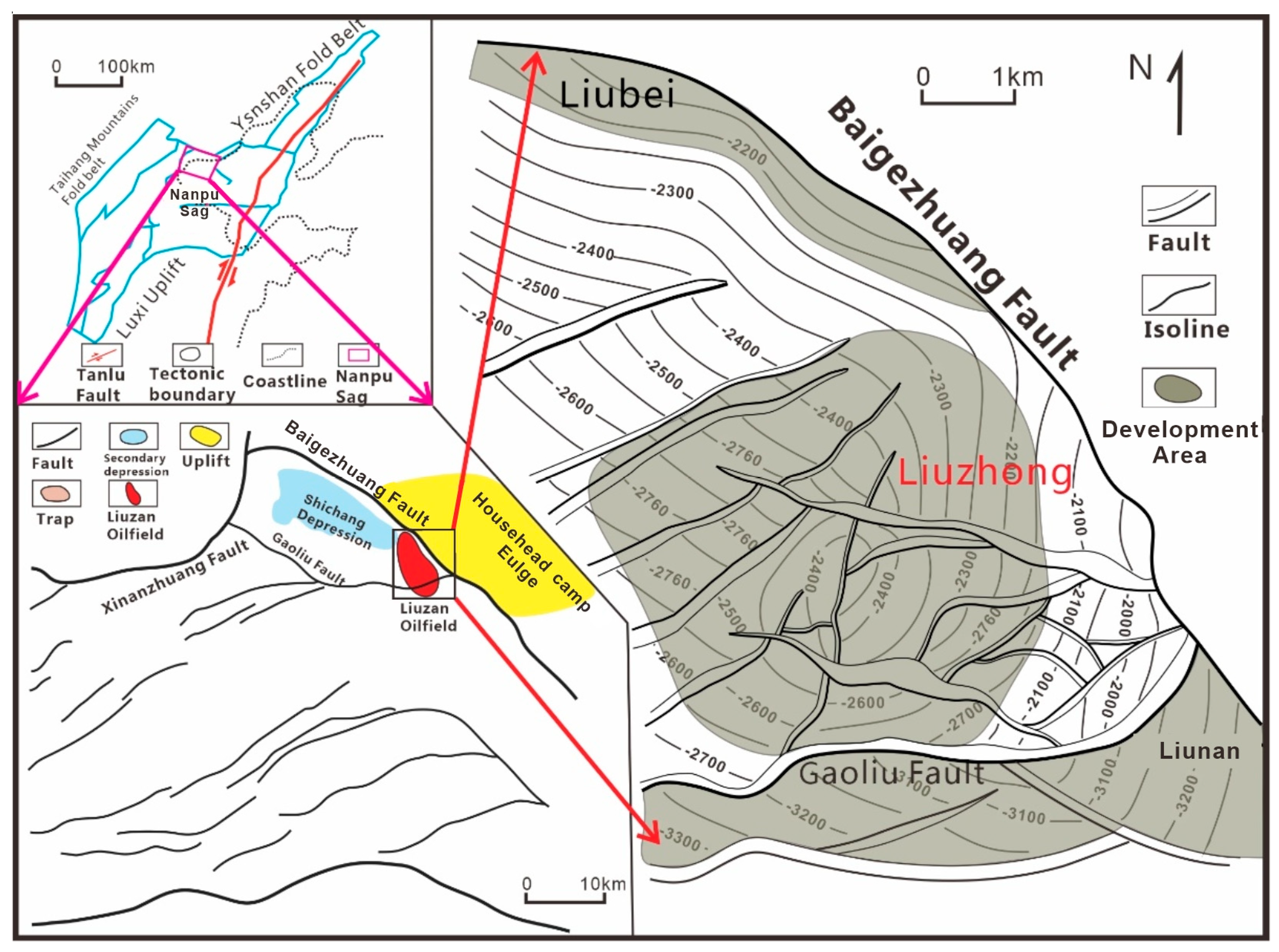
Figure 1. Map of the tectonic position of the Liuzhong Oilfield.
Energies 17 00115 g001
Figure 2. Stratigraphic division of the Paleocene System in the Liuzhong Oilfield.
Energies 17 00115 g002
Figure 3. Pro-gradational reflection characteristics of the seismic section along the sediment source direction.
Energies 17 00115 g003
Figure 4. Core photographs show Shahejie Formation in the Liuzhong Oilfield: (a) carbon chip, Well L31-4, 3253.22 m; (b) ferruginous nodules, Well L31-4, 3252.20 m; (c) gray-green muddy siltstone, Well L17-9, 2595.41 m; (d) interlocking stratigraphy, Well L1-13, 2927.53 m; (e) medium gravel, Well L2, 2952.52 m.
Energies 17 00115 g004
Figure 5. Response characteristics in logging of sedimentary microfacies in the Liuzhong Oilfield: (a) type of distributary channel curve; (b) type of mouth bar curve; (c) type of distributary channel flank curve.
Energies 17 00115 g005
Figure 6. Elevation difference of a single channel of the Liu 1 fault block.
Energies 17 00115 g006
Figure 7. Inter-channel deposition of a single channel of the Liu 1 fault block.
Energies 17 00115 g007
Figure 8. Differences in curve characteristics of a single channel of the Liu 1 fault block.
Energies 17 00115 g008
Figure 9. “Thick-thin-thick” phenomenon of single channel boundary of the Liu 1 fault block.
Energies 17 00115 g009
Figure 10. Deposition pattern diagram: (a) combination mode of “Upper channel and Lower Bar”; (b) sand body contact relationship of “Upper channel and Lower Bar”.
Energies 17 00115 g010
Figure 11. Plane distribution of microfacies and plane superposition diagram of sand body microfacies of I1-3 in the Liuzhong Oilfield: (a) plane superposition diagram of the sand body; (b) plane distribution of microfacies.
Energies 17 00115 g011
Figure 12. Sedimentary model of the Liuzhong Oilfield.
Energies 17 00115 g012
Figure 13. Distribution of microfacies in the Liuzhong Oilfield: (a) VIII 2-1 depositional microphase diagram; (b) II 1-1 depositional microphase diagram.
Energies 17 00115 g013
Figure 14. Lateral contact pattern and connectivity pattern of a single sand body in the study area.
Energies 17 00115 g014
Figure 15. Tracer monitoring analysis of Well Liu 28-11 and Well Liu 28-5.
Energies 17 00115 g015
Figure 16. Connectivity superposition analysis of tracer monitoring results and microfacies in II 2-2 of the Liu 28-1 fault block.
Energies 17 00115 g016
Table 1. Classification of the vertical connectivity of single sand bodies in the study area.
Styles of Vertical Stacking Diagram of Stacking StyleClassification of Sand Connectivity
Vertical tangential
superposition
Energies 17 00115 i001Connectivity
Vertical isolationEnergies 17 00115 i002No connectivity
Table 2. Classification of plane connectivity of single sand body in the study area.
Lateral Stacking StyleDiagram of the Lateral Stacking StyleDegree of Connectivity
Side-cutting typeEnergies 17 00115 i003Connected
Mouth bar
contact type
Energies 17 00115 i004Weakly connected
Flanking contact
type
Energies 17 00115 i005No connectivity
Table 3. Tracer water drive speed of Well Liu 28-11 and Well Liu 28-5.
Injection WellMonitoring WellLayerPeak Time (d)Water Drive Speed (m/s)
L28-11L28-5II 2-2731.5
II 2-11011.1
Disclaimer/Publisher’s Note: The statements, opinions and data contained in all publications are solely those of the individual author(s) and contributor(s) and not of MDPI and/or the editor(s). MDPI and/or the editor(s) disclaim responsibility for any injury to people or property resulting from any ideas, methods, instructions or products referred to in the content.