Article

Numerical Simulation on the Influence of Inlet Flow Characteristics on the Performance of a Centrifugal Compressor

1
Key Laboratory of Mechanics on Disaster and Environment in Western China, Lanzhou University, Lanzhou 730000, China
2
College of Civil Engineering and Mechanics, Lanzhou University, Lanzhou 730000, China
3
China North Engine Research Institute, Tianjin 300400, China
*
Author to whom correspondence should be addressed.
Energies 2023, 16(9), 3869; https://doi.org/10.3390/en16093869
Submission received: 14 April 2023 / Revised: 29 April 2023 / Accepted: 29 April 2023 / Published: 2 May 2023

Abstract

:
Although inlet bent pipes are usually adopted due to limited installation space, the influences of different bend pipes on the inlet flow characteristics and performance of centrifugal compressors are still unclear. The numerical simulation of a centrifugal compressor is established and validated by experimental results with the case of a straight inlet pipe. Then, the internal flow characteristics of the centrifugal compressor with a 90-degree bent pipe (p90) and Z-shaped bent pipe (pz) are simulated and discussed. The results show that the adoption of two inlet bent pipes reduces the performance of the centrifugal compressor to a certain extent, which reduces more greatly with pz, with a maximum reduction of 6.82% in pressure ratio and 14.83% in efficiency, respectively. The pressure ratio and efficiency reduction of the centrifugal compressor both increase with the increment of distortion degree, which maintains the increasing trend as the flow rate increases, and the maximum distortion degree of p90 and pz reaches 0.0351 and 0.0479, respectively. The reduction degree of the pressure ratio shows a power–law relationship with the distortion degree, while the reduction degree of efficiency shows an exponential relationship with it. The flow characteristics at the outlet section of the inlet pipe affect the flow field distribution at the inlet of the impeller, and the distortion area ranges of the total pressure and axial velocity at the inlet of the impeller are near 72°–144° in the circumferential direction for p90, while those of pz are close to 108°–180° and 288°–360°. When the flow with a high distortion degree enters the impeller, a large area with high turbulent kinetic energy is formed in the downstream flow channel, resulting in an increase in the flow loss.

1. Introduction

Due to the high single-stage pressure ratio, compact structure, and low production cost [1], centrifugal compressors are widely used in engineering machinery, such as turbochargers, air compression systems, and small gas turbines [2]. With the increasing application of turbochargers in the engineering field, the requirements for the performance of its core component, i.e., the centrifugal compressor, become higher. Centrifugal compressors are usually designed on the premise of a uniform gas inlet, while in practice, due to the space and layout limitations of the supercharger, bent inlet pipes are usually used, resulting in an asymmetrical inlet environment [3]. The existence of this asymmetric inlet environment can cause a deviation from the design operating conditions, which leads to changes in the performance of the centrifugal compressor [4,5].
The early research on asymmetric inlets for compressors was mainly conducted for axial-flow compressors [6,7]. With the wide application of centrifugal compressors, investigation into a non-uniform gas inlet has gradually received more attention with the methods of experimental measurements and numerical simulations. The non-uniform flow conditions at the inlet of a centrifugal compressor are usually modelled by using distortion generators in an experiment [8]. By changing the installation form of the inlet honeycomb to generate asymmetric flow at the inlet of a low-speed centrifugal compressor, Ariga et al. [9] found that the inlet distortion changed the incidence angle of gas at the inlet of the impeller and exerted unfavorable influences on the efficiency. Dickmann et al. [10] conducted research on the blade excitation of a centrifugal compressor under the condition of asymmetric inlet flow caused by a bent pipe, and the experimental results showed that the amplitude magnitude of the blade varied with the flow rate. Zemp et al. [11] and Kammerer and Abhari [12] also experimentally investigated the non-uniform inlet flow of a centrifugal compressor, it was found that the fluctuation amplitude of the blade load was the largest at the leading edge, and it decreased with the decrease in flow rate. In the relevant experimental study, the distortion generators are usually used to generate the distortion flow field, but this method is different from the distorted flow field in practical application [13]. Although the experimental methods are important in the studies of centrifugal compressors, they require a long period, high expenditure consumption, and are greatly restricted by a variety of environmental conditions and testing methods [14].
With the rapid development of the CFD (Computational Fluid Dynamics) method, it has been widely used in the research of rotating machinery due to the advantages of short application period, low implementation cost, and high functionality [15]. Li et al. [16,17,18] numerically simulated the effect of a 90-degree bend pipe on the performance of centrifugal compressors and found that the distance between the bent pipe outlet and impeller inlet leads to more deterioration on the performance of centrifugal compressors, which provided a reference for the arrangement of the inlet bent pipe for the same type of compressors. Zhang et al. [19] investigated the performances of the centrifugal compressor with different inlet pipes by changing the length and diameter of the inlet pipe through numerical simulation, with the results indicating that different inlet pipes resulted in different loads at the compressor inlet; therefore, the performance of the centrifugal compressor changed. The research of Kim et al. [20] showed that the secondary flow intensity of the fluid through the bent pipe was related to the curvature radius of the pipe, the secondary flow intensity showed a trend of decay with the increase in the curvature radius of the bent pipe, and some bent pipes also caused the total pressure distortion of the flow in the pipe. Zhao et al. [21] adjusted the installation angle of the 90-degree pipe in the circumferential direction. The numerical results showed that the adjustment of the installation angle of the inlet pipe reduced the efficiency of the compressor. It is recommended to avoid the unfavorable direction of the installation angle for the inlet pipe. Wang et al. [22] carried out experimental and numerical research on the performance changes in centrifugal compressors caused by a 180-degree inlet elbow with different installation angles. The results showed that the degree of the centrifugal compressor’s performance degradation caused by the 180-degree inlet elbow was related to its circumferential installation position, in which the inlet elbow with the circumferential installation angle of 240° led to a pressure ratio decrease of nearly 5% and an efficiency decrease of nearly 7.5% at the near-choke point condition. Wang et al. [23] numerically investigated the influence of the distortion of air intake on the performance of the compressor by installing a plug-in plate distortion simulator; however, the diversity of the distortion flow between the distortion simulator and the practical operation conditions creates different results. Tong et al. [24] investigated the distortion of the inlet flow field caused by sharing a single inlet manifold of the twin compressor, and the results showed that the performance of the right compressor was more likely to deteriorate than the left compressor, and it was related to the location of the intake distortion.
However, there is usually an inlet pipe structure with only a single elbow, which was established in the previous research on the non-uniform inlet flow conditions of centrifugal compressors. In practical application, it is very likely that the double elbow or more complex inlet pipe will be adopted for the centrifugal compressor [21,22], and the differences and variation rules of the effects between the single elbow and double elbow inlet pipes on the performance of centrifugal compressors are rarely involved in current research. The same type and different intensity of non-uniform flow conditions generally exist in reality but receive less attention in present studies. The research on the flow field of centrifugal compressors is mostly on qualitative analysis, while there is also a lack of quantitative characterization. Moreover, the inlet distortion is often simulated by setting different inlet pressure conditions at the circumferential position in the numerical simulation, which lacks authenticity for the inlet flow distortion caused by the inlet elbow in practical engineering applications [25]. Therefore, for the centrifugal compressor with different inlet bent pipes in practical applications, the quantitative characterization of the non-uniform flow with different intensities at the inlet of the centrifugal compressor, as well as its influence on the changes in the performance of the centrifugal compressor, still needs to be further investigated.
In this paper, systematic research on the influence of different inlet bent pipes on the performance of a centrifugal compressor was carried out. The inlet distortion in practical engineering applications was considered. By analyzing the flow field changes of the centrifugal compressor with different inlet elbows, the variation laws of influence from the inlet elbows to the performance of the centrifugal compressor were obtained. Firstly, the two different inlet bent pipes, i.e., a single 90-degree bent pipe (p90) and Z-shaped bent pipe (pz), were established, which resulted in the flow distribution of the vortex flow with different intensities. Then, the quantitative characterizations of the non-uniform flow of p90 and pz were acquired and represented by the distortion degree. Finally, the quantitative relationship between the distortion degree and performance reduction degree of the centrifugal compressor was given, which can be used as reference for the selection and optimization of the inlet bent pipes, as well as for the performance prediction of the centrifugal compressor.

2. Methodology

2.1. Model Centrifugal Compressor

The object of this study is a turbocharger centrifugal compressor with structures including an inlet pipe, impeller, vaneless diffuser, and volute. The meridian plane of the centrifugal compressor is shown in Figure 1. The main geometric parameters of the centrifugal compressor are listed in Table 1.

2.2. Numerical Simulation Method

The commercial CFD software, Fluent, was employed to simulate the three-dimensional compressible flow characteristics of the centrifugal compressor by solving the Reynolds Average Navier–Stokes (RANS) equations. The shear stress transport (SST) κ-ω turbulence model was adopted, and the pressure and velocity were coupled. The convection term was discretely solved in the second-order upwind scheme; the diffusion term was solved in the first-order upwind scheme.
Continuity equation:
ρ t + d i v ( p V ) = 0 ,
where
d i v ( p V ) = ( ρ u ) x + ( ρ v ) y + ( ρ w ) z ,
where ρ is the density of the gas, with a unit of kg m−3; u, v, and w are velocities in x, y, and z directions with a unit of m s−1, respectively. t means time, and the unit is s.
The momentum equations in x, y, z directions are as follows:
( ρ u ) t + d i v ( p u V ) = p x + d i v ( μ   g r a d   u ) + S u ,
( ρ v ) t + d i v ( p v V ) = p y + d i v ( μ   g r a d   v ) + S v ,
( ρ w ) t + d i v ( p w V ) = p z + d i v ( μ   g r a d   w ) + S w ,
where μ denotes the dynamic viscosity of the fluid, the unit is pa·s; p is the pressure on the fluid, which unit is pa; Su, Sv, and Sw are generalized source terms.
Energy equation:
( ρ T ) t + d i v ( p V T ) = d i v ( λ c p   g r a d   T ) + S T ,
where T represents the temperature with a unit of k; λ is the heat transfer coefficient of the fluid; cp denotes the specific heat capacity, and ST is the source term.
SST κ-ω turbulence model is widely used in the research of turbomachinery, which combines the advantages of the standard κ-ε turbulence model in simulating the near-wall flow and the standard κ-ω turbulence model in simulating the flow outside the boundary layer [26]. The SST κ-ω turbulence model was more suitable for simulating the complex vortex flows in compressors from the perspectives of computation accuracy and consumption. It has been employed with high frequency in the numerical research of compressors [27,28]. The expressions of κ and ω equations are as follows:
The equation of turbulent kinetic energy κ:
( ρ k ) t + ( ρ k u i ) x i = x j ( Γ k k x j ) + G k Y k + S k ,
The equation of turbulent dissipation rate ω:
( ρ ω ) t + ( ρ ω u i ) x i = x j ( Γ ω ω x j ) + G ω Y ω + D ω + S ω ,
where Gk is the turbulent kinetic energy due to the average velocity gradient; Yk and Yω represent the dissipation of κ and ω caused by turbulence, respectively. Dω is the convection–diffusion term; Sk and Sω are source terms; Γk and Γω denote the effective diffusion coefficients of κ and ω, respectively.
The effective diffusion coefficient is calculated as follows:
Γ k = μ + μ t σ k ,
Γ ω = μ + μ t σ ω ,
where σk and σω are the turbulent Prandtl numbers of k and ω, respectively; μt is turbulent viscosity.
The steady-state numerical simulation research was conducted in this research, and the steady-state solution variables obtained are independent of time. When the flow involves moving parts including the rotating impellers, the flow around the moving parts can be modeled as a steady-state problem with respect to the moving frame with a multiple reference frame, which can render a problem that is unsteady in the stationary frame steady with respect to the moving frame. It is possible to transform the equations of fluid motion to the moving frame such that steady-state solutions are possible. The main objective of this article is to obtain the quantitative relationship between centrifugal compressor’s performance and inlet flow characteristics, so the steady-state solution results can be used in the research of this article.
The boundary conditions need to be set when solving the governing equations; the boundary conditions are given as follows:
The pressure inlet condition was applied to the inlet of the domain, and the value of total pressure and total temperature were given. The axial inlet direction was adopted, and the operating pressure was 101,325 pa. Within the operating condition of a large flow rate, the flow rate changes slightly while the outlet pressure changes greatly, so that the static pressure can be given at the outlet of the computational domain. Since the change in pressure is small and the flow rate variation is relatively large, the mass flow outlet condition was set to obtain better calculation convergence when the centrifugal compressor operated under a lower flow rate. The boundary conditions under different rotational speeds are concluded in Table 2.
During the process of numerical simulation, the MRF (multiple reference frame) is employed to solve the problems that involve multiple moving parts, and the computational domain is divided into the rotating zone and stationary zone, with interface boundaries separating the zones. The individual zones can be assigned different rotational speeds, and zones that contain the rotating components can be solved using the moving reference frame equations, whereas stationary zones can be solved with the stationary frame equations. The ideal gas was selected as the working medium, and the adiabatic no-slip boundary was applied to the flow boundary. The corresponding speed and direction were given for the blades and hub; the rest of the walls were set as stationary walls. The residual of convergence was set to 10−6. In the process of numerical simulation, the variation of the pressure ratio and the mass flow rate of the inlet and outlet were monitored as the determining conditions for the convergence of the calculation.

2.3. Mesh generation and independence test

ANSYS TurboGrid is a specialized software for the structured mesh generation of rotating machinery, which can optimize the topology of the impeller passage by using the ATM Optimized function [29] to generate the high-quality structured mesh. The boundary layer mesh was set for the impeller, with a first-layer height of 0.007 mm. The unstructured mesh with high adaptability to complex geometries was chosen to generate the mesh of volute [30], which has asymmetric geometry in the circumferential direction.
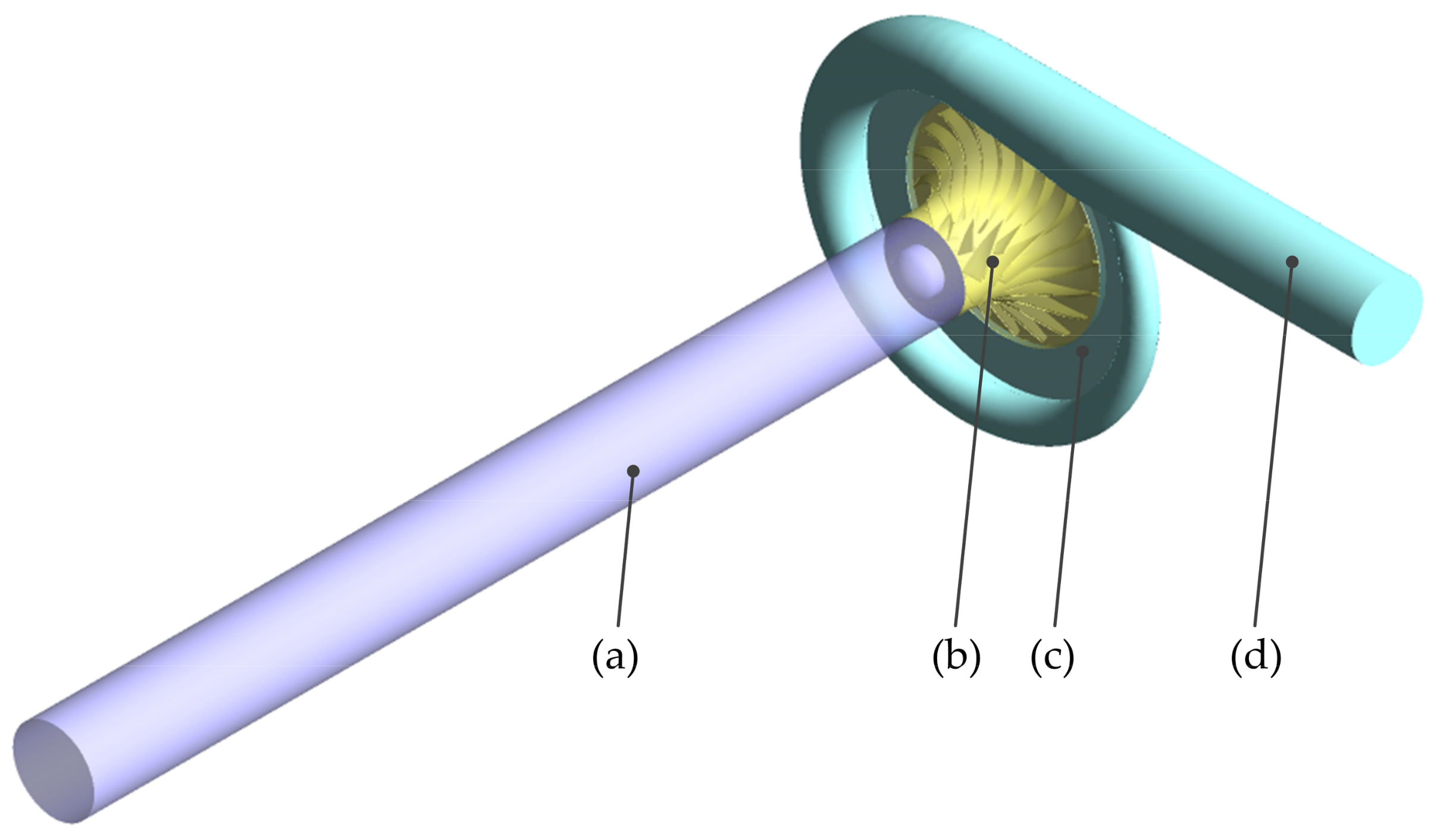
The computational domain of the centrifugal compressor with a straight inlet pipe is shown in Figure 2. The whole passage mesh of impeller and the leading-edge mesh of the blade are shown in Figure 3a, and the mesh of the vaneless diffuser and volute is shown in Figure 3b.
In order to eliminate the influence of the mesh number on the numerical simulation results and save computational resources, it is necessary to carry out the mesh independence test of the computational domain. Under the premise of ensuring the consistency of the turbulence model, boundary conditions, mesh topology, and the height of the first layer, ten groups of mesh schemes were established, as listed in Table 3. The pressure inlet condition and mass flow rate outlet condition are adopted as the operational condition of the mesh independence test, and the inlet total pressure is set to 101,325 pa while the mass flow rate is set to 0.043 kg/s under the rotational speed of 6 × 10⁴ rpm. The pressure ratio and efficiency of the centrifugal compressor are taken as the reference parameters obtained by simulation. The variation of the reference parameters with the number of mesh can be seen in Figure 4. It shows that the pressure ratio and efficiency remain constant when the total mesh number exceeds 8,983,652, so the total mesh number of the computational domain is finally determined to mesh scheme 7.

3. Numerical Simulations of Centrifugal Compressor with Different Inlet Bent Pipes

The accuracy of the numerical simulation was validated by the experimental results of the centrifugal compressor with the straight inlet pipe. Then, the two different structures of inlet bent pipes were established, which were a 90-degree bent pipe (p90) and Z-shaped bent pipe (pz). The performance of the centrifugal compressor with p90 and pz was obtained through the results of relevant numerical simulation. The distorted flow field at the outlet of the bent pipe was then quantitatively characterized based on the analysis of the numerical results.

3.1. Validation of Numerical Simulation

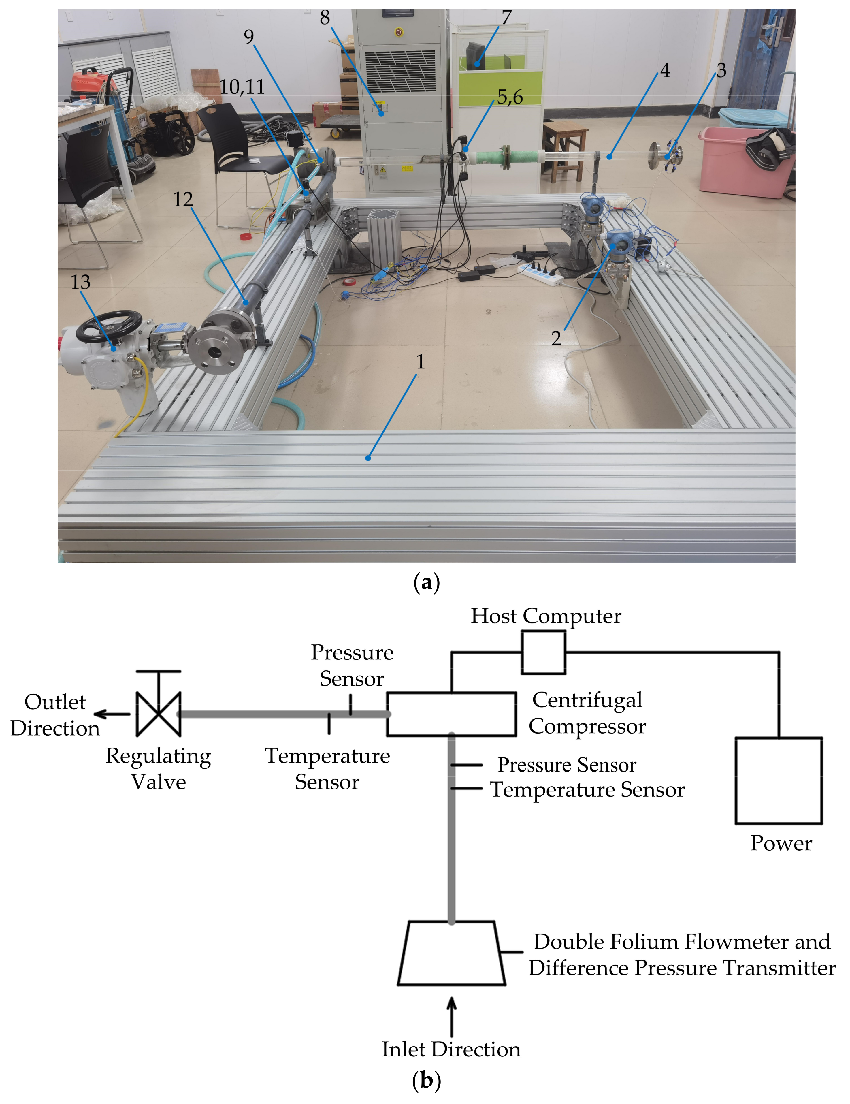
In order to validate the accuracy of the numerical simulation method, the performance of the object centrifugal compressor was experimentally tested through the centrifugal compressor’s performance test bench. The arrangement of the test bench and the schematic diagram are shown in Figure 5a,b, and the measurement of the mass flow rate, pressure, temperature, and the rotational speed are mainly involved in the performance test bench of the centrifugal compressor. During the progress of the experiment, the DC stabilized power supply was used to provide the DC voltage to the computer of the centrifugal compressor, which converted the current into three-phase AC power and then provided the power to drive the compressor. The rotational speed of the centrifugal compressor was adjusted using the PLC program, and the outlet pressure was changed by adjusting the regulating valve installed at the outlet pipe. At the same time, real-time information such as the rotational speed and the temperature of the centrifugal compressor were transmitted to the computer. The inlet flow rate can be obtained from the double folium flowmeter after the outlet pressure is stable, as well as the value of the pressure sensor and the temperature sensor, which were installed at the inlet and outlet pipelines. By regulating the rotational speed and outlet pressure, the inlet and outlet pressure as well as temperature of the centrifugal compressor were finally obtained under different rotational and flow rates. Information such as the pressure and temperature under different operating conditions was obtained after the centrifugal compressor operated stably, and the obtained data were averaged within five minutes. The performance test process was repeated three times, and the standard deviations of the performance were added in Figure 6 in the form of error bars.
By substituting the measured inlet and outlet pressure and temperature into the pressure ratio and efficiency formulas, the performance of the centrifugal compressor at the rotational speeds of 6 × 10⁴, 8 × 10⁴, and 10 × 104 rpm can be acquired. The pressure ratio and efficiency can be calculated by the following equations:
π c = P 2 P 1 ,
η = T a ( π k 1 k 1 ) T 4 T a = π k 1 k 1 T 4 T a 1 ,
where P1 and P2 represent total pressure at the inlet and outlet of the centrifugal compressor while Ta and T4 represent the total temperature. k denotes the isentropic coefficient.
The performance obtained from the numerical simulation was compared with the results measured from the experiment, as shown in Figure 6. It can be seen that the trend of the simulated performance of the centrifugal compressor at different rotational speeds was consistent with the experimental performance, and the result was in good agreement with the error between them, which was less than 10%. The difference between the simulation and experimental results may have been caused by factors such as manufacturing accuracy deviation, as well as the difference between the heat loss caused by the cooling water during the experiment’s progress and the adiabatic boundary condition during simulation [31]. It can be concluded that the corresponding high-efficiency point and operating range of the centrifugal compressor can be simulated accurately, which indicates that the numerical simulation method adopted in this paper was credible and can be used to simulate the flow characteristics of the centrifugal compressor.

3.2. Analysis of the Performance Difference on the Centrifugal Compressor

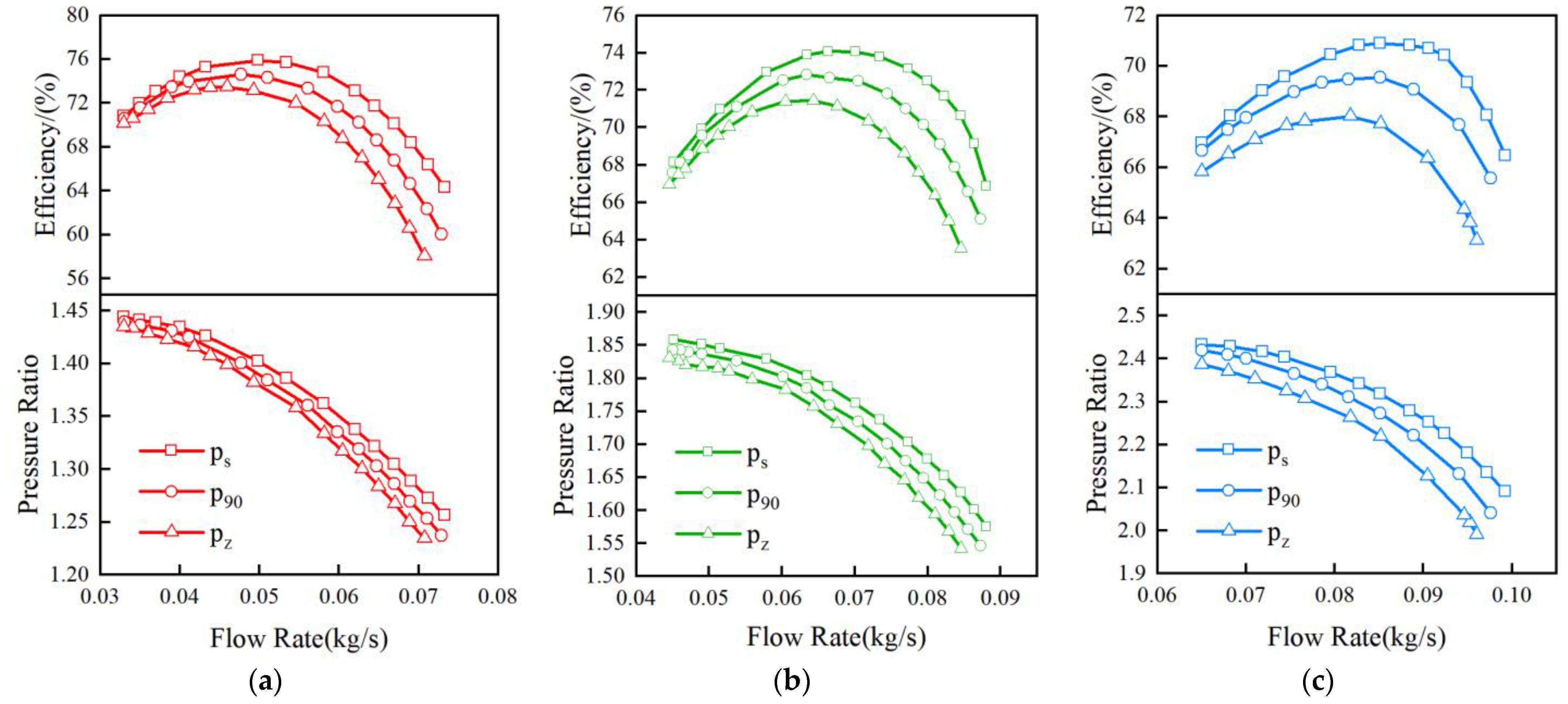
The structure of the inlet pipe varied with the actual installation space requirements, which resulted in the adoption of the bent pipe on the centrifugal compressor. Two different inlet bent pipes, a 90-degree bent pipe (p90) and a Z-shaped bent pipe (pz), were established in this paper. Based on the validated numerical simulation method, the performance of the centrifugal compressors with different inlet pipes was simulated under different rotational speeds by adjusting boundary conditions. The computational domain of centrifugal compressors with the straight inlet pipe, i.e., ps, p90, pz, is shown in Figure 7. The same length of the center axis from the inlet to the outlet of the three inlet pipes was set up, which was about 10 times the impeller inlet diameter. The flow field in the inlet pipes with the chosen length was fully developed, and the linear loss along the pipes remained the same, so the factor that affected the performance of the centrifugal compressor with different inlet pipes was mainly caused by their structures.
The performances of the centrifugal compressor with three inlet pipes at the rotational speeds of 6 × 10⁴, 8 × 10⁴, and 10 × 104 rpm are shown in Figure 8a,b,c, respectively. The considered range for Reynolds number under different rotational speeds and different mass flow rates was about 7 × 10⁴ to 22 × 104. It can be seen from the figures that the performance of the centrifugal compressor with both inlet elbows was lower than that of the centrifugal compressor with a straight inlet pipe at each rotational speed condition. The reduction degree in both pressure ratio and efficiency increased with the increase in flow rate, indicating that the increase in flow rate leads to the strengthening of the inlet distortion, which resulted in a greater reduction in the performance of the centrifugal compressor. The pressure ratio and efficiency of the centrifugal compressor of p90 were lower than that of pz at each rotational speed condition, which indicated that although the length of the pipes was the same, the distorted flow at the outlet of pz had a greater impact on the performance of the centrifugal compressor than that of p90.
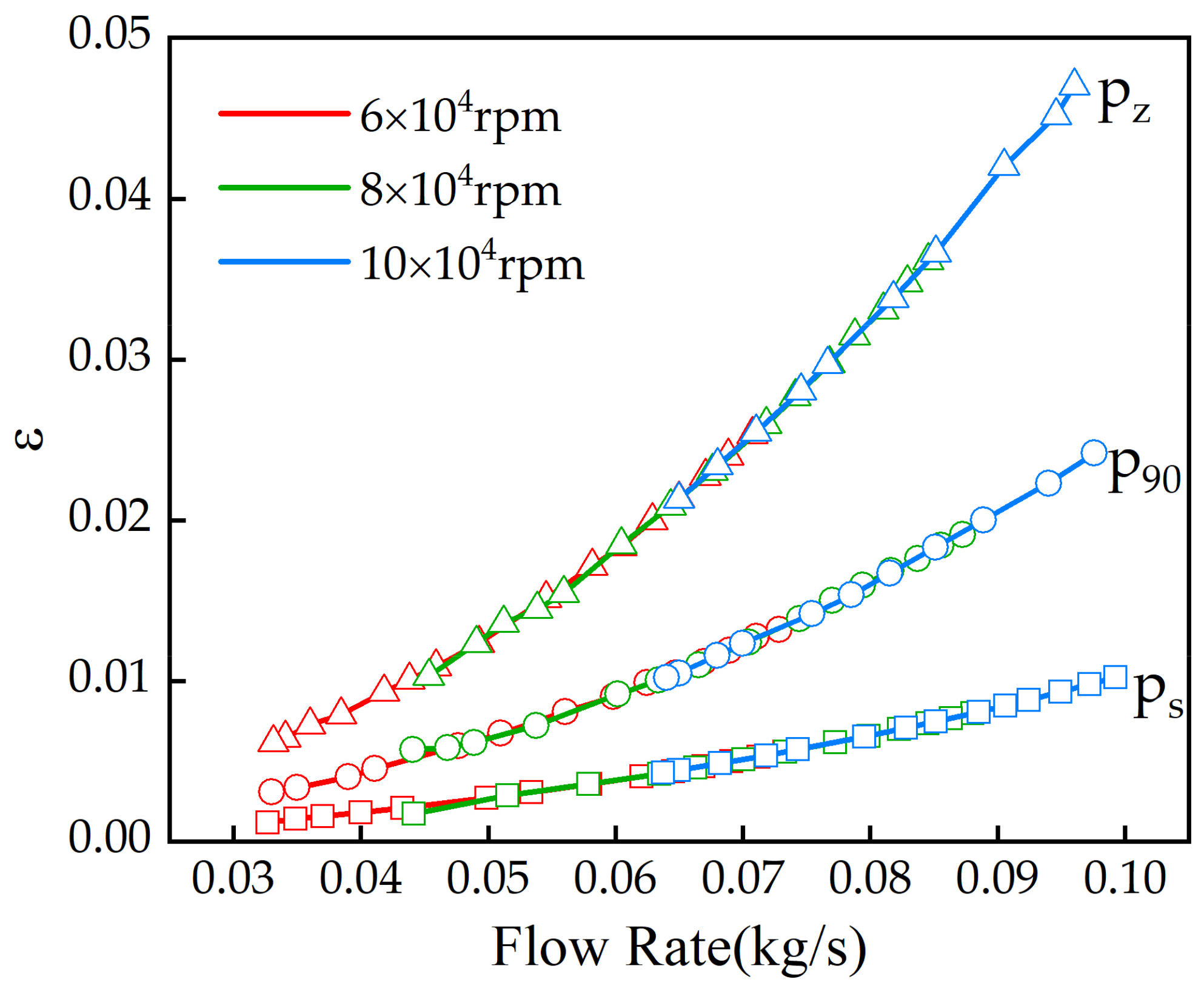
The distribution of flow became non-uniform when the air flowed through the inlet elbow, and a part of the total pressure loss was also generated. The part of total pressure loss was one of the reasons for the performance degradation of the centrifugal compressor with an inlet elbow. The total pressure loss coefficient ε was defined to describe the degree of the total pressure loss in different inlet pipes; it was calculated as follows:
ε = P in P out P in ,
where Pin and Pout are the total pressure at the inlet and outlet of the pipeline, respectively.
The variation of the total pressure loss coefficient ε with flow rates for the three inlet pipes at 6 × 10⁴, 8 × 10⁴, and 10 × 104 rpm are shown in Figure 9. It can be seen from the figure that the ε of three inlet pipes increased continuously with the increase in the flow rate under different rotational speeds. The total pressure loss coefficient ε for the same inlet pipe maintained the same increasing trend. With the increase in the flow rate at each rotational speed, the total pressure loss coefficient ε of pz was the highest, which reached 0.047, and the ε of p90 was 0.024, while it was the lowest for ps. The variability of the total pressure loss coefficient ε of the inlet pipes indicated that, in addition to the length of the pipes, the structure of the inlet pipes had a significant influence on the total pressure loss in the pipelines, which affected the performance of the centrifugal compressor. The distribution of the flow field formed at the outlet of the elbows changed due to its structure, so the flow field entering the impeller was different as well, which resulted in different effects on the centrifugal compressor’s performance.

3.3. Distortion Flow Field Analysis of Different Inlet Pipes

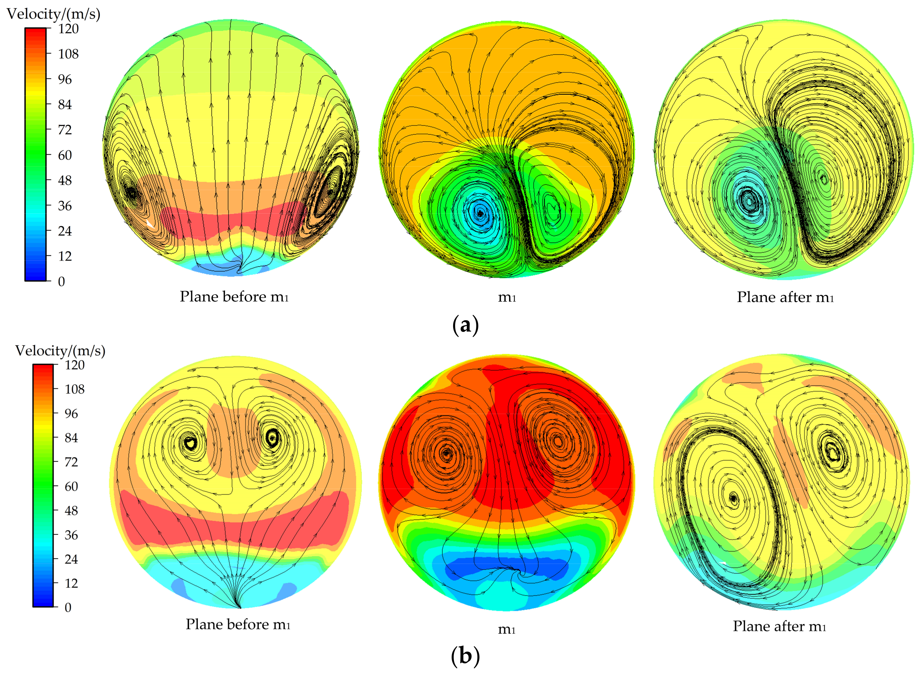
Since the flow field distribution that formed at the outlet of the inlet pipes was different, and it determined the distribution at the inlet of the impeller, which further affected the performance of the centrifugal compressor, it was necessary to analyze the flow field at the outlet of different inlet elbows, which was conductive to understand the influence of flow distribution on the performance of the centrifugal compressor. Figure 10 shows the 3D streamlines of the outlet section of p90 and pz, and three planes are shown in Figure 10 as well, while the position of the m1 plane is marked in Figure 7. From the 3D streamlines, it can be seen that the obvious vortex flow was formed as the air flowing out from the elbow for a certain distance to the position of approximately the m1 plane. Since the impeller had the operating rotational speed and the structure of the hub, the flow characteristics of the plane near the inlet of the impeller were affected. Figure 11 shows the streamline and velocity distribution in three planes of p90 and pz, which were the plane before m1, m1, and the plane after m1. It can be found from Figure 11 that the flow distribution in the plane before m1 of both p90 and pz showed a high degree of symmetry, but the vortex flow was not yet fully developed. When the flow reached the m1 plane, the flow distribution with an obvious symmetric vortex was formed. As the plane after m1 got closer to the impeller inlet, the flow distribution of the plane was influenced by the impeller, while the symmetry of the flow on the plane was gradually reduced. Since the flow of the m1 plane maintained the distribution state of the vortex flow flowing through the elbows and had a certain distance from the inlet of the impeller, the distribution of the flow field was less influenced by the rotating effect of the impeller; thus, the m1 planes of ps, p90, and pz at 100 mm from the inlet were selected, respectively.
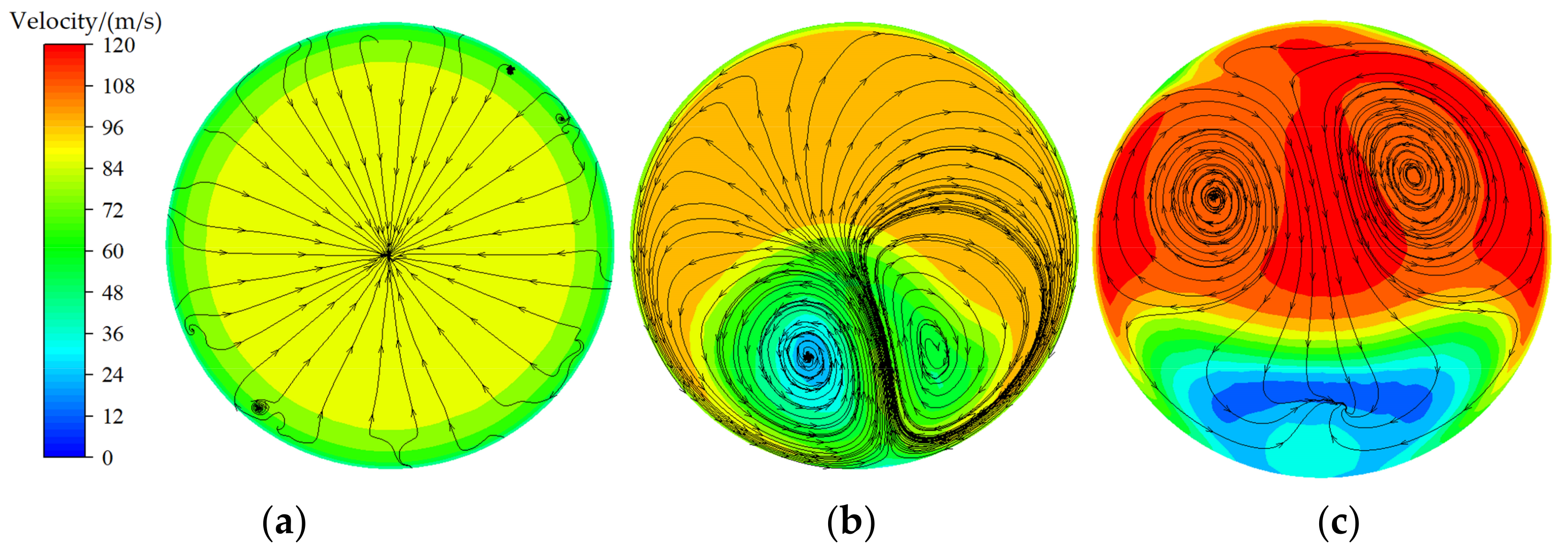
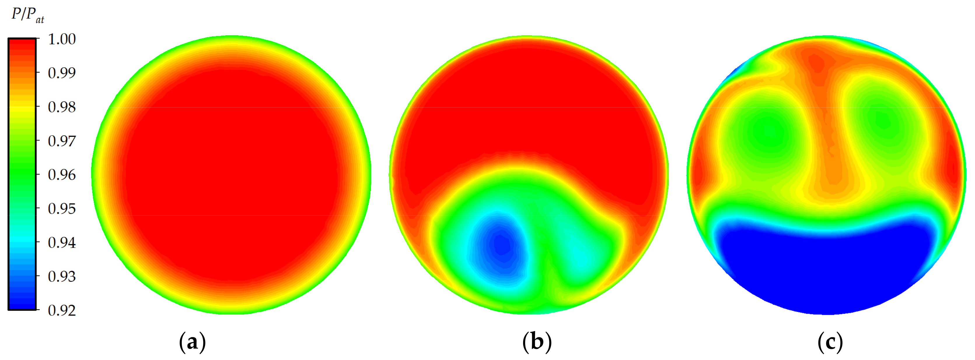
The streamline and dimensionless total pressure distribution at the outlet of the three inlet pipes, i.e., ps, p90, and pz, under the flow rate condition of near the high-efficiency point at 10 × 104 rpm are shown in Figure 12 and Figure 13, and the flow rate of different pipes was selected as Q = 0.08514 kg/s, 0.08512 kg/s, and 0.08515 kg/s, respectively, where the dimensionless total pressure was the ratio between the local total pressure and the local atmospheric pressure Pat, which was taken as 101,325 pa. As can be seen from Figure 12 and Figure 13, the distribution of the streamline and total pressure distribution in ps were both uniform. Combined with the streamline and total pressure distribution at the outlet of p90 in Figure 12 and Figure 13, it can be seen that the flow characteristics close to the symmetric vortex were formed at the outlet of the p90, and the total pressure showed a distribution state of near-symmetric. The symmetrical vortex was located near the inner side of p90, which was the lower area of plane m1 viewed from the inlet direction. The velocity and total pressure of air in the region where the symmetrical vortex was located were relatively lower, while they were higher in the upper area of plane m1. When the non-uniformed flow distribution that formed at the outlet of the inlet elbow enters the impeller with high rotational speed, it has an important impact on the operating capacity of the compressor.
The flow distribution close to the symmetric vortex was also formed at the outlet of pz, and the total pressure distribution showed a nearly symmetrical distribution as well. The symmetrical vortex at the outlet of pz was located in the upper area of plane m1, where the velocity and total pressure were both higher than that of the lower area. The distortion area extent of total pressure at the outlet of pz was larger, and the distance between the symmetrical vortex distortion cores was longer than that of p90. The vortex flow in the high-pressure area had higher kinetic energy and had a greater impact on the flow passage when it entered the rotating impeller, which resulted in a higher influence on the pressure ratio and efficiency of the centrifugal compressor. The average total pressure of ps was the highest, followed by p90, and pz was the lowest.

3.4. Quantitative Characterization of the Flow Field at the Outlet of Different Inlet Pipes

In order to clarify the influence of inlet pipe structures on the distortion degree at the outlet of elbows, as well as to analyze their impact on the flow characteristics at the inlet of the impeller, it is necessary to quantitatively describe the distortion degree at the outlet of the inlet pipe. Since the non-uniformity at the outlet of elbows caused by its structures was mainly manifested as circumferential distortion [8], the quantitative description of the total pressure distortion at the outlet of the inlet pipes can be characterized by the circumferential distortion degree [32]. The circumferential distortion degree was used to quantify the total pressure distortion degree at a certain radius of the outlet section of the pipes, which indicated the amplitude of the reduction on the total pressure at a certain radius. The circumferential distortion degree was defined as follows:
C D = P A V i P A V L O W i P A V i ,
where (PAV)i is the average total pressure at a certain radius; (PAVLOW)i represents the average of the part below the average total pressure.
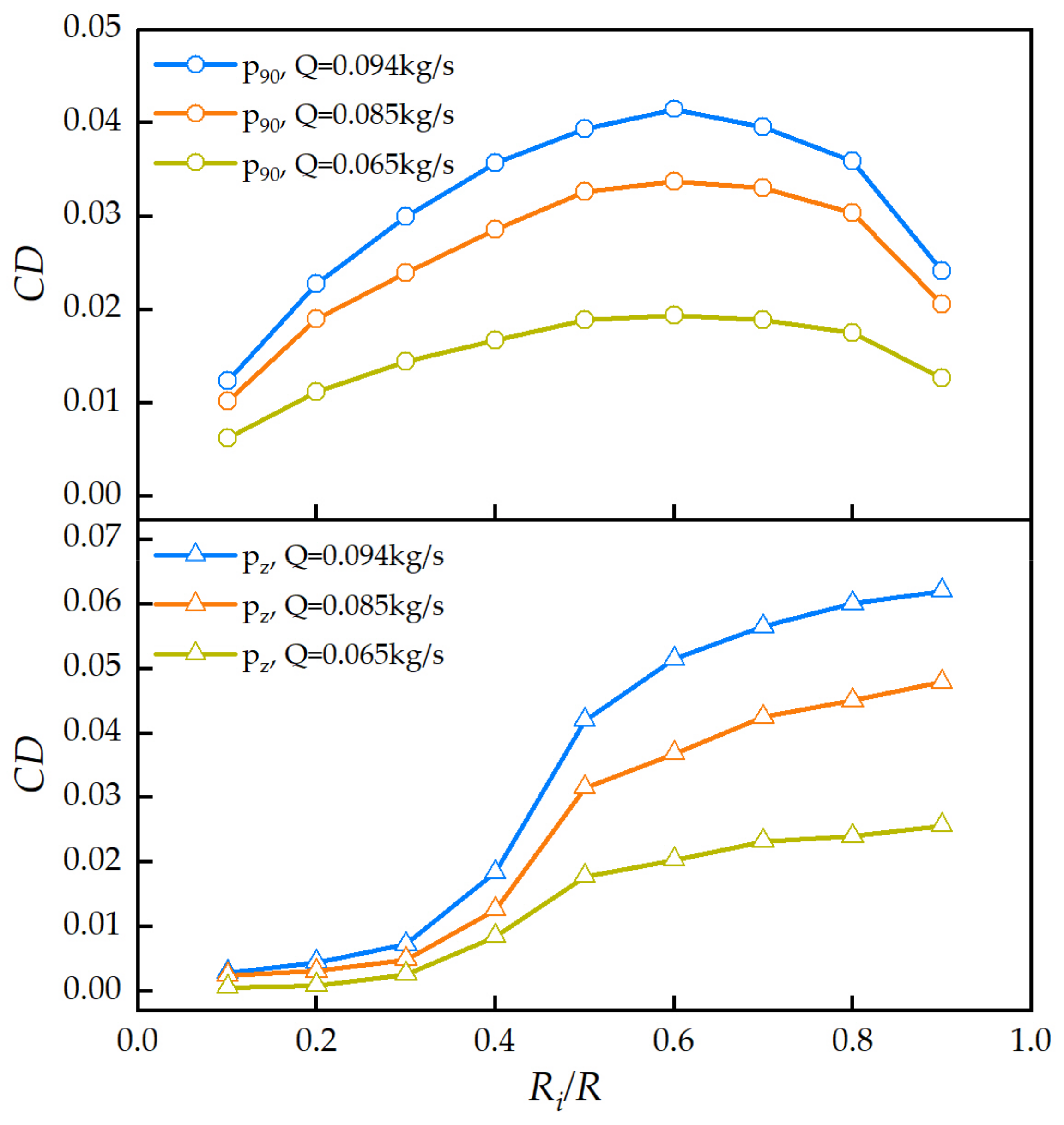
Figure 14 shows the nine circles selected on plane m1, which were 0.1 to 0.9 times the radius, respectively, and R was the radius of the chosen circles. The position of plane m1 is shown in Figure 7. The CD of nine circles on plane m1 of two inlet elbows at different flow rates with the rotational speed of 10 × 104 rpm is shown in Figure 15. The horizontal coordinate was the dimensionless radius of the circles on plane m1, which was the ratio between the radius of the chosen circles and the radius of the inlet pipe.
The CD at the outlet of two inlet elbows was different in the circumferential direction. The CD of p90 increased with the increase in radius at first and then decreased, which reached the maximum at 0.5 to 0.6 times the radius of inlet pipes. The CD of pz increased continuously with the increase in the radius. It can be seen from Figure 15 that the circumferential total pressure of p90 was reduced to a higher degree near the middle radius area, while the CD of pz reached the highest at the area near the wall of pipe. The maximum CD of pz under different flow rate conditions was always higher than that of p90. The air in the lower radius area of the pipe converged into the flow passage when it entered the impeller since it had the structure of a hub, so the flow field of the lower radius area had little influence on the flow characteristics at the inlet of the impeller. The inlet pipes with the higher distortion degree formed at a higher radius area will insert greater impact on the flow field distribution at the inlet of the impeller.
In order to establish the quantitative relationship between the circumferential distortion degree at the outlet of the inlet pipe and the performance reduction degree of the centrifugal compressor, the circumferential distortion degree of the plane (PCD) on plane m1 was introduced, which was defined as follows:
P C D = i = 1 N R i C D i N ,
where N = 9, Ri is the radius of the chosen circles on plane m1, and CDi is the circumferential distortion degree of each circumference on plane m1. The pressure ratio and efficiency of the centrifugal compressor with three inlet pipes at several operating conditions with the same flow rate were extracted under different rotational speeds. The reduction degree in pressure ratio and efficiency of the centrifugal compressor with inlet bent pipes was defined as follows:
δ π = π i π s π s × 100 % ,
δ η = η i η s η s × 100 % ,
where δπ and δη are the reduction degree of the pressure ratio and efficiency, respectively. πi and ηi denote the pressure ratio and efficiency of the centrifugal compressor with p90 or pz, respectively, while πs and ηs represent that of ps.
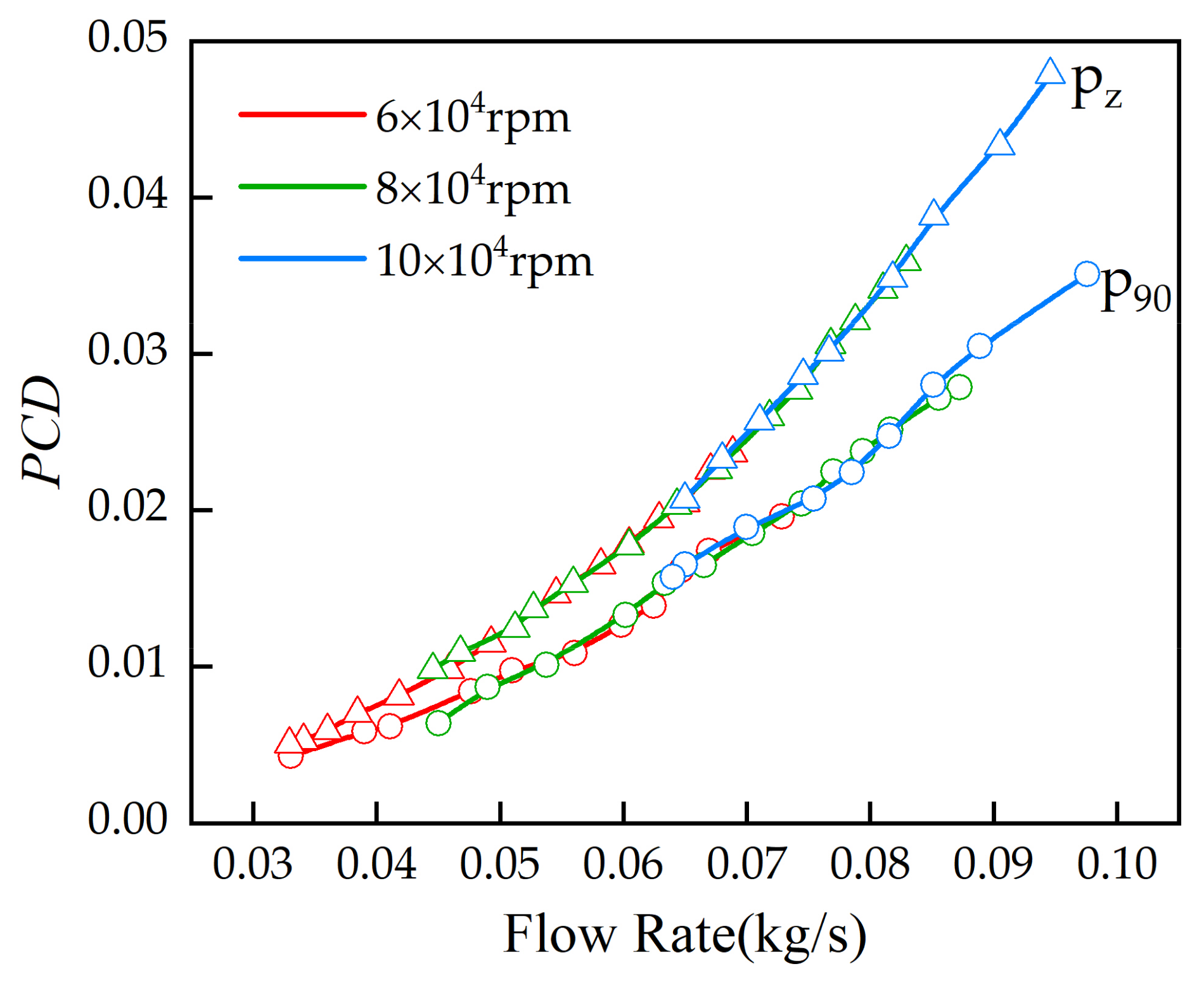
The variation of the PCD with the flow rate on plane m1 of two inlet elbows under different rotational speeds is shown in Figure 16. It can be seen from the figure that the PCD increased with the increasing flow rate under each rotational speed condition, and the PCD of pz was higher than that of p90. The growth of PCD of the two inlet elbows at different rotational speeds remained the same trend, respectively. The maximum PCD on plane m1 of p90 and pz reached 0.0351 and 0.0479, respectively, at the large flow rate condition.
The corresponding PCD and performance reduction degree of the centrifugal compressor with p90 and pz at several operating points with the same flow rate were extracted, respectively, and then the quantitative relationship between them was established, which is shown in Figure 17. The power function was used to fit the relationship between PCD and the reduction degree of the pressure ratio, while the exponential function was used to fit the relationship between PCD and the reduction degree of efficiency, and the fitting functions were as follows:
δ π = a × P C D b ,
δ η = c 1 + c 2 e d P C D ,
where a, b, c1, c2, and d are the coefficients of fitting functions, respectively, and the value of each coefficient at different rotational speeds is shown in Table 4 and Table 5. The fitting degree of the fitting functions showed a high value in each rotational speed, which indicated that the reliability of the fitting functions was high. The variation of each coefficient with the rotational speed is shown in Figure 18a,b. The figures showed that the variation of the pressure ratio and efficiency reduction degree with the rotational speed of p90 and pz was similar. It can be seen from Figure 16 that the reduction degree of the pressure ratio and efficiency of the centrifugal compressor tended to increase with the increase in PCD. The PCD of pz was higher than that of p90 under different rotational speed conditions, which resulted in the higher performance reduction degree of the centrifugal compressor with pz than that of p90. The results indicated that the different distortion degrees of the flow field that formed at the outlet of the elbows resulted in different degradation degrees of the centrifugal compressor’s performance. The maximum pressure ratio reduction degree of the centrifugal compressor with p90 and pz reached 3.11% and 6.82%, respectively, while their maximum efficiency reduction degrees were 7.37% and 14.83%, respectively. The quantitative relationship between the distortion degree at the outlet of inlet elbows and the performance reduction degree can provide reference for the performance prediction of the centrifugal compressor which adopted inlet bent pipes.

4. Analysis of Flow Characteristics in the Impeller of the Centrifugal Compressor

As the main operating component of the centrifugal compressor, the distribution of the flow field at the inlet of the impeller determined the distribution of the flow characteristics in the impeller passage, which affected the performance of the centrifugal compressor. The flow field distribution at the inlet of the impeller was directly related to the connected structure upstream. When the straight inlet pipe was adopted to the centrifugal compressor, the distribution of the flow flied at the impeller inlet was uniform. While it tended to the distribution state asymmetrically with the adoption of inlet bent pipes, the asymmetric distribution of flow characteristics changed with different inlet elbows; the change trend differed with the distribution of the flow field at the outlet of the inlet elbows as well. To find out the variation in the flow field at the inlet and flow passage of the impeller when the different structures of the inlet elbow were installed, it is necessary to extract the distribution information of the flow field at the inlet as well as the flow passage of the impeller, which was beneficial to obtain the reasons for the change in the performance of the centrifugal compressor with inlet bent pipes.

4.1. Total Pressure Distribution at the Inlet of the Impeller

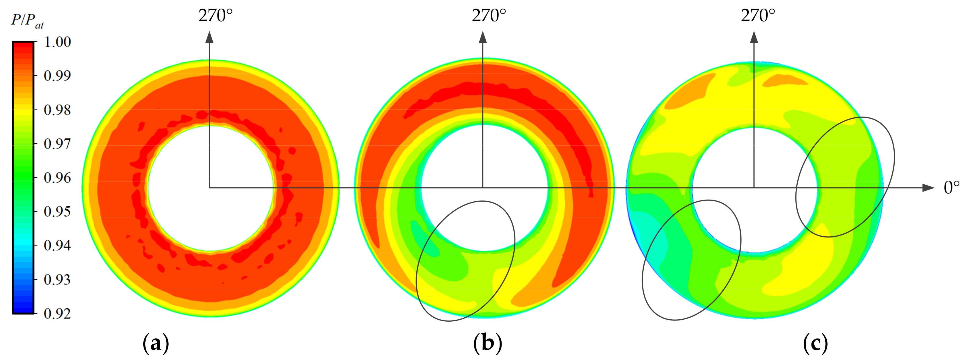
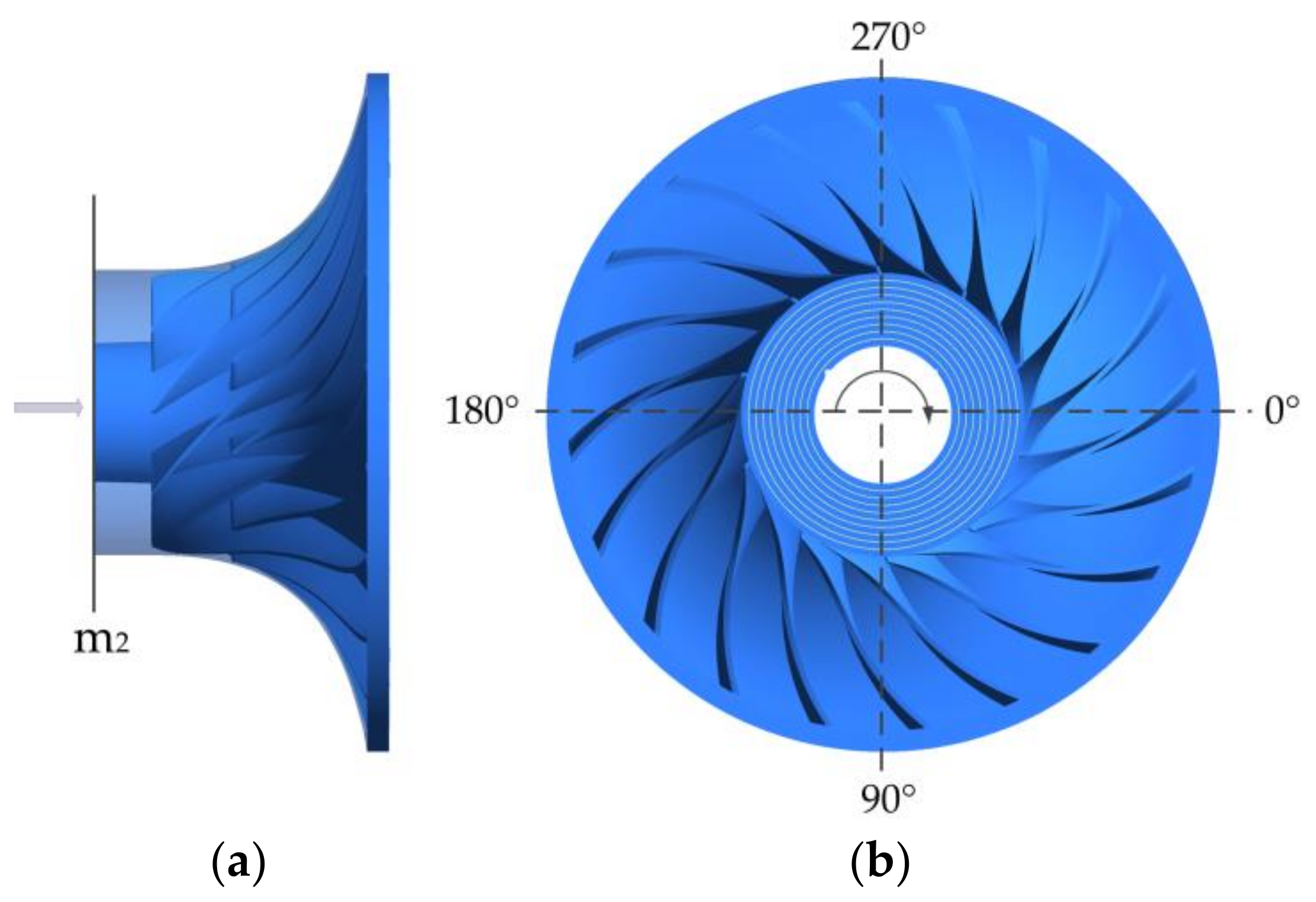
The dimensionless total pressure distribution at the impeller inlet of the centrifugal compressor with different inlet pipes is shown in Figure 19 The dimensionless total pressure was the ratio of the local total pressure to the local atmospheric pressure (Pat), which was taken as 101,325 pa. The chosen plane at the inlet of the impeller was plane m2 viewed from the inlet direction, which is shown in Figure 20a. The rotation direction of the impeller is shown in Figure 20b, which was clockwise viewed from the inlet direction, and the circumferential angle was defined as positive along the rotation direction of the impeller.
The pressure distribution at the outlet of ps was uniform, so it presented the uniform distribution state at the inlet of the impeller. The position of the vortex at the outlet of p90 and pz was different, while the influence of the flow field distribution on the inlet of the impeller was varied as well. The total pressure distortion area at the impeller inlet and the outlet of the elbows remained the same distribution in the circumferential direction. When the flow with a large pressure gradient at the outlet of elbows entered the impeller, the flow field distribution with a large pressure change was also formed at the corresponding position of the impeller inlet. The distance between the total pressure distortion cores at the outlet of p90 was relatively close, which formed one total pressure distortion area at the inlet of the impeller. There are two total pressure distortion areas formed at the inlet of the impeller because of the longer distance between the distortion cores of total pressure at the outlet of pz.
The variation of the dimensionless total pressure along the circumferential direction at different blade heights on plane m2 is shown in Figure 21. The nine blade heights selected on plane m2 are shown in Figure 20b, which represented 0.1 times to 0.9 times the height of the impeller passage. The flow in the high total pressure area was absorbed into the impeller due to the high rotational speed of it, which affected the distribution of total pressure at the inlet of the impeller. The flow with the vortex formed at the outlet of pz in the high total pressure area entered the rotating impeller; it resulted in a larger range of the distortion area in the circumferential direction, while the reduction degree of the centrifugal compressor decreased more significantly. The vortex flow that existed in the lower pressure region of p90 caused a relatively smaller range of circumferential total pressure distortion at the inlet of the impeller. It can be seen, combined with Figure 19, that the circumference position of total pressure distortion at the impeller inlet of the centrifugal compressor with p90 was near 72°–144°, while those of pz were around 108°–180° and 288°–360°.

4.2. Axial Velocity Distribution at the Inlet of the Impeller

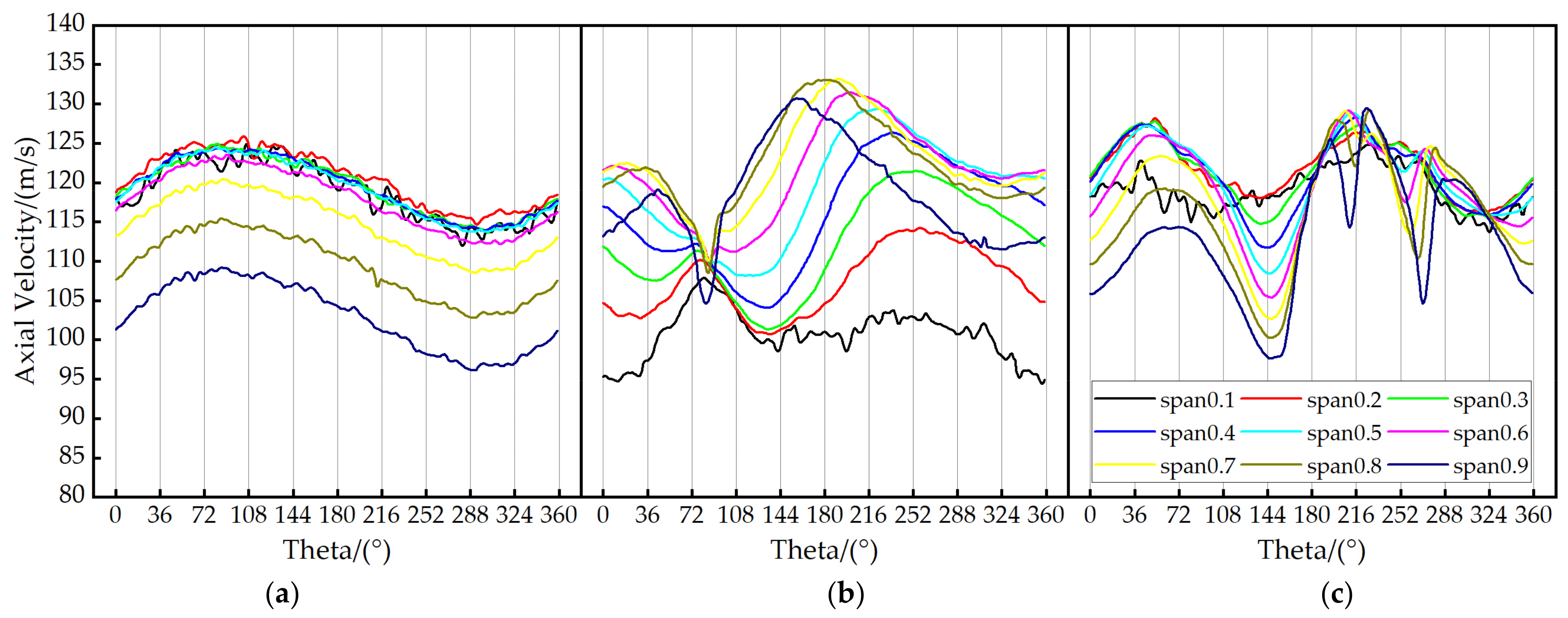
As shown in Figure 22, the variation of the axial velocity along the circumferential direction at different blade heights on plane m2 is presented. It can be seen from the figures that the distribution of axial velocity at different blade heights of the impeller with the ps scheme was not distorted in the circumferential direction. The position where the axial velocity changed significantly at the inlet of the impeller with p90 and pz was similar to the total pressure distortion area in the circumferential direction. When the swirling flow in the area with a great pressure gradient entered the impeller, the axial velocity decreased at the inlet of the impeller because of the disturbed uniform distribution of the axial velocity by the swirling flow. The entrainment effect of the vortex flow leads to the non-uniform distribution of the flow rate in the impeller passages as well.

4.3. Mass Flow Rate Distribution at the Inlet of the Impeller

The air entered the passage from the inlet of the impeller along the axial direction and finally flowed out along the radial direction. The distribution of the mass flow rate was directly related to the axial velocity distribution at the inlet of the impeller. The mass flow rate distribution in each flow passage of the centrifugal compressor with different inlet pipes is shown in Figure 23, while the vertical coordinate was the ratio between the mass flow rate in each flow channel and the total mass flow rate of the impeller, which represented the proportion of mass flow rate in each passage. The decrease in the mass flow rate was caused by the reduction in axial velocity at the corresponding circumferential position of the impeller inlet. The flow passage with more mass flow rate corresponded to the circumferential area with high axial velocity at the inlet of the impeller. According to the results in Figure 23, the distribution of mass flow rate at the inlet of the impeller with the ps scheme was relatively uniform, and there was no dramatic change in the mass flow rate ratio of each passage. The mass flow rate decreased in the passage which corresponded to the circumferential position with significant change in the axial velocity. The variation range of mass flow rate in the impeller passage was larger in the circumferential direction, which was caused by the greater distortion range of the axial velocity at the inlet of the impeller. The reason for the change in the mass flow rate distribution may be that the uniform flow characteristics were disturbed after the swirling flow entered the impeller passage, resulting in the existence of some radial flow of air, which hindered part of the axial flow.

4.4. Distribution of Turbulence Kinetic Energy in the Impeller Passage

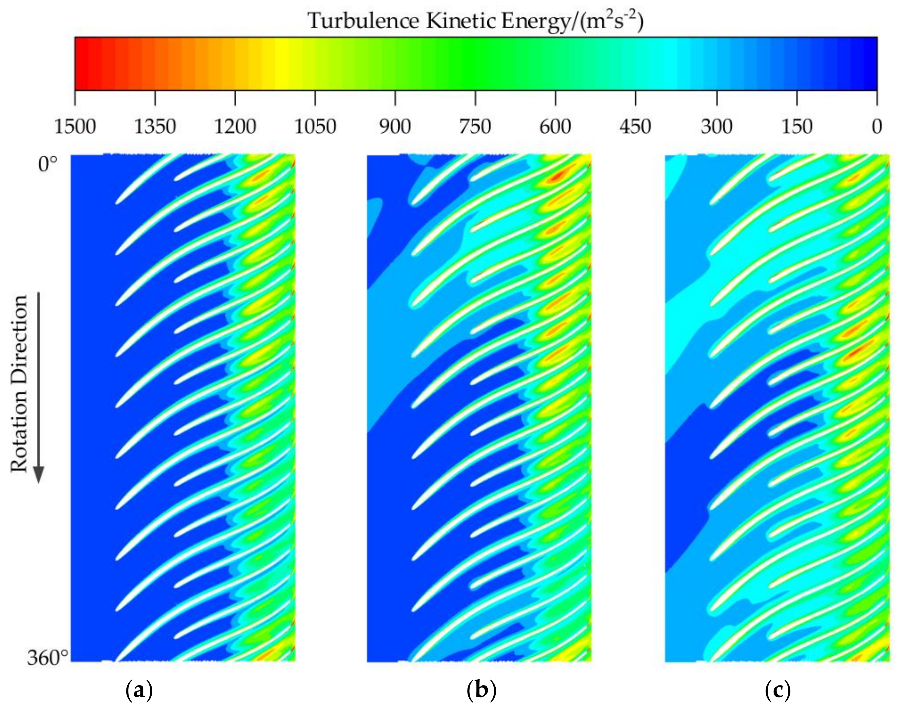
Turbulence kinetic energy is an important parameter to characterize the turbulence intensity. Therefore, it was conductive to analyze the stability of the flow field by extracting the distribution information of the turbulence kinetic energy in the impeller passage. Figure 24 shows the turbulence kinetic energy distribution at 0.5 times the blade height in the passage of the impeller with different inlet pipe schemes. It can be seen from Figure 24 that the turbulence kinetic energy distribution in the passage of the impeller with ps was uniform in the circumferential direction, while that of p90 and pz showed a symmetrical state in the circumferential direction due to the distorted flow field formed at the inlet of the impeller, which resulted in the existence of the areas with high turbulence kinetic energy. Part of the fluid energy was consumed because of the increase in turbulence kinetic energy in the impeller, and more flow losses were caused. The distortion degree formed at the outlet of pz was higher than that of p90, so the range of the high turbulence kinetic energy area that formed in the passage of the impeller with pz was larger, and the non-uniformity in the circumferential direction was stronger. The results indicated that the flow characteristics in the flow channel of the impeller with pz were more unstable, so the performance reduction degree of the centrifugal compressor with pz was higher than that of p90. The area with high turbulence kinetic energy in the passage of the impeller with p90 and pz remained similar with the position with the total pressure distortion at the inlet of the impeller. The high turbulence kinetic energy area in the passage of the impeller with p90 was near 72°–144° while that of pz was close to 108°–180° and 288°–360°. It can be seen from the turbulence kinetic energy distribution in the impeller passage that the non-uniformity of the flow characteristics at the impeller inlet was directly caused by the distorted flow field formed at the outlet of elbows and resulted in the instability of the flow in the impeller passage as well as more flow loss. Thus, the performance of the centrifugal compressor was reduced.

5. Conclusions

Based on the Fluent software, the performance of a centrifugal compressor with a straight inlet pipe under different rotational speeds was numerically simulated by solving the Reynolds Average Navier–Stokes equations; the accuracy of the numerical simulation method with the SST k-ω turbulent model was validated by experimental results. Then, the different inlet bent pipes of 90 degrees and Z-shaped bent pipe were established, and the corresponding performance of the centrifugal compressor was obtained based on the validated numerical simulation method. Finally, the flow characteristics at the outlet of inlet pipes as well as the impeller passage were analyzed, respectively. The following main conclusions were drawn:
(1) The performance of the centrifugal compressor with two inlet bent pipes was decreased compared with the straight inlet pipe, while the performance reduction degree of the centrifugal compressor with pz was higher than that of p90. The maximum pressure ratio reduction degree of the centrifugal compressor with p90 and pz reached 3.11% and 6.82%, respectively, and their maximum efficiency reduction degrees were 7.37% and 14.83%.
(2) The total pressure loss coefficient of the inlet pipes increased continuously with the increase in the flow rate. The total pressure loss coefficient of pz was higher than that of p90 under different rotational speed conditions, which reached 0.024 and 0.047 for p90 and pz at the condition with high rotational speed.
(3) The circumferential distortion degree of the plane increased with the increasing flow rate under each rotational speed condition, while that of p90 and pz reached 0.0351 and 0.0479 at the large flow rate condition. The pressure ratio reduction had a power–law relationship with the circumferential distortion degree of the plane, while the efficiency reduction degree had an exponential relationship with it.
(4) The uniform flow characteristics were disturbed after the swirling flow distribution close to symmetric vortex that formed at the outlet of p90 and pz entered the impeller passage. The distortion area of the total pressure and axial velocity at the inlet of the impeller-maintained similarity with the distortion area at the outlet of elbows, which was near 72°–144° for p90, while those of pz were close to 108°–180° and 288°–360°.
(5) Due to the higher distortion degree formed at the outlet of pz, the high turbulence kinetic energy area in the impeller passage with pz was wider, and the non-uniformity in the circumferential direction was stronger, which resulted in more flow loss. The area with high turbulence kinetic energy was similar to the distorted area at the inlet of the impeller.

Author Contributions

Conceptualization, X.L.; methodology, Y.Z. (Yanli Zhang); validation, G.C. and Y.Z. (Yang Zhao); formal analysis, D.T.; investigation, X.L.; data curation, X.L.; writing—original draft preparation, X.L.; writing—review and editing, J.Z.; supervision, N.H. All authors have read and agreed to the published version of the manuscript.

Funding

This research was funded by the Key Laboratory of National Defense Science and Technology Project, grant number 6142212200108, the Natural Science Foundation Project of Hebei province, grant number A2021202014, and the Basic Product Innovation Research Program (20221001).

Data Availability Statement

Not applicable.

Conflicts of Interest

The authors declare no conflict of interest.

Nomenclature

psStraight inlet pipe
p9090-degree bent pipe
pzZ-shaped bent pipe
εTotal pressure loss coefficient
PLocal total pressure (unit: pa)
PatLocal atmospheric pressure (unit: pa)
PinPressure of the inlet of the domain (unit: pa)
PoutPressure of the outlet of the domain (unit: pa)
CDCircumferential distortion degree
PCDCircumferential distortion degree of the plane
πcPressure ratio of the centrifugal compressor
ηEfficiency of the centrifugal compressor
δπReduction degree of the pressure ratio
δηReduction degree of the efficiency
QMass flow rate of the centrifugal compressor (unit: kg/s)

References

  1. Sun, Z.Z.; Wang, B.T.; Zheng, X.Q.; Kawakubo, T.; Tamaki, H.; Numakura, R. Effect of bent inlet pipe on the flow instability behavior of centrifugal compressors. Chin. J. Aeronaut. 2020, 33, 2099–2109. [Google Scholar] [CrossRef]
  2. Krain, H. Review of Centrifugal Compressor’s Application and Development. J. Turbomach. 2005, 127, 25–34. [Google Scholar] [CrossRef]
  3. Li, C.; Bai, S.Z.; Li, Y.Z.; Zhang, J.J.; Zhang, J.M. Effects of curved tube intake on centrifugal compressor efficiency. Intern. Combust. Engine Power Plant 2020, 37, 26–31. [Google Scholar]
  4. Han, F.H.; Mao, Y.J.; Tan, J.J. Influences of flow loss and inlet distortions from radial inlets on the performances of centrifugal compressor stages. J. Mech. Sci. Technol. 2016, 30, 4591–4599. [Google Scholar] [CrossRef]
  5. Yang, C.; Wang, W.L.; Zhang, H.Z.; Yang, C.M.; Li, Y.Z. Investigation of stall process flow field in transonic centrifugal compressor with volute. Aerosp. Sci. Technol. 2018, 81, 53–64. [Google Scholar] [CrossRef]
  6. Zhang, Y.F.; Chu, W.L.; Lu, X.G. Numerical Simulation of Effect of Inlet Total-Pressure Distortion on Subsonic Axial-Flow Compressor. J. Northwestern Polytech. Univ. 2009, 27, 12–17. [Google Scholar]
  7. Toge, T.D.; Pradeep, A.M. Experimental investigation of stall inception of a low speed contra rotating axial flow fan under circumferential distorted flow condition. Aerosp. Sci. Technol. 2017, 70, 534–548. [Google Scholar] [CrossRef]
  8. Zhou, S.D.; Wen, Q. The Effects of Inlet Total Pressure Radial Distortions on the Performance Characteristics of a Centrifugal Compressor. Gas Turbine Exp. Res. 2005, 18, 5. [Google Scholar]
  9. Ariga, I.; Kasai, N.; Masuda, S.; Watanabe, Y.; Watanabe, I. The Effect of Inlet Distortion on the Performance Characteristics of a Centrifugal Compressor. J. Eng. Power 1983, 105, 223–230. [Google Scholar] [CrossRef]
  10. Dichmann, H.P.; Wimmel, T.S.; Szwedowicz, J.; Filsinger, D.; Roduner, C.H. Unsteady Flow in a Turbocharger Centrifugal Compressor: Three-Dimensional Computational Fluid Dynamics Simulation and Numerical and Experimental Analysis of Impeller Blade Vibration. J. Turbomach. 2006, 128, 455. [Google Scholar] [CrossRef]
  11. Zemp, A.; Kammerer, A.; Abhari, R.S. Unsteady Computational Fluid Dynamics Investigation on Inlet Distortion in a Centrifugal Compressor. J. Turbomach. 2010, 132, 93–94. [Google Scholar] [CrossRef]
  12. Kammerer, A.; Abhari, R.S. Blade Forcing Function and Aerodynamic Work Measurements in a High Speed Centrifugal Compressor with Inlet Distortion. J. Eng. Gas Turbines Power 2010, 132, 95–105. [Google Scholar] [CrossRef]
  13. Li, J.C.; Lei, J.W.; Liu, Y.; Du, J.; Lu, X.X.; Song, Q.B. Distribution characteristics of compressor stall precursor under circumferential distortion. J. Aerosp. Power 2021, 36, 1356–1366. [Google Scholar]
  14. Zhang, Y.X.; Li, Z.L. Summary of Numerical Simulation Methods for Flow in Fluid Machinery. Fluid Mach. 2006, 34, 6. [Google Scholar]
  15. Jathar, K.S.; Kulkarni, V.V. An Elementary Study of Computational Fluid Dynamics for Various Engineering Applications—A Review. Int. Res. J. Eng. Technol. 2015, 2, 1292. [Google Scholar]
  16. Li, D.; Yang, C.; Chen, S.; Qi, M.X. Numerical simulation on inlet distortion of centrifugal compressor with 90° bent pipe. J. Aerosp. Power 2010, 25, 8. [Google Scholar]
  17. Li, D.; Yang, C.; Chen, S.; Zhang, Z.Q. Unsteady Characteristics on Inlet Distortion of Bend-Pipe of Centrifugal Compressor. Trans. CSICE 2011, 29, 7. [Google Scholar]
  18. Li, D.; Yang, C.; Zhou, M.; Zhu, Z.F.; Wang, H. Numerical and experimental research on different inlet configurations of high speed centrifugal compressor. Sci. China Technol. Sci. 2012, 55, 174–181. [Google Scholar] [CrossRef]
  19. Zhang, J.; Ma, H.W.; He, H.; Gu, J.B. Numerical simulation of effects of the inlet pipe on the performance of a centrifugal compressor. J. Aerosp. Power 2009, 24, 7. [Google Scholar]
  20. Kim, J.; Yadav, M.; Kim, S. Characteristics of Secondary Flow Induced by 90-Degree Elbow in Turbulent Pipe Flow. Eng. Appl. Comput. Fluid Mech. 2016, 8, 229–239. [Google Scholar] [CrossRef]
  21. Zhao, B.; Sun, H.; Wang, L.L.; Song, M.X. Impact of Inlet Distortion on Turbocharger Compressor Stage Performance. Appl. Therm. Eng. 2017, 124, 393–402. [Google Scholar] [CrossRef]
  22. Wang, L.L.; Lao, D.Z.; Liu, H.; Zhao, B.; Yang, C. The Influence of Different Installation Angles of 180° Inlet Bend Pipe on the Centrifugal Compressor Performance. J. Eng. Thermophys. 2014, 35, 5. [Google Scholar]
  23. Wang, Y.H.; Hu, Q.S.; Wang, Z.Y.; Wang, M. Study on the Influence of Distortion Intensity on the Aerodynamic Performance of Compressor. J. Eng. Therm. Energy Power 2021, 36, 110–116. [Google Scholar]
  24. Tong, D.; Tian, H.Y.; Xing, W.D.; Liu, Y.; Liu, X.Y. Simulation study on the distortion on inlet flow field caused by twin centrifugal compressor sharing a single inlet distortion. Chin. Intern. Combust. Engine Eng. 2020, 41, 63–69. [Google Scholar]
  25. Zhang, H.G.; Li, Q.; Dong, F.Y.; Chu, W.L. Mechanism of Affecting the Performance and Stability of an Axial Flow Compressor with Inlet Distortion. J. Therm. Sci. 2021, 30, 15. [Google Scholar] [CrossRef]
  26. Zeng, Y.; Wang, H.B.; Sun, M.B.; Wang, C.; Liu, X. Review on SST turbulence model improvements. Acta Aeronaut. Et Astronaut. Sin. 2023, 44, 027411. [Google Scholar]
  27. Cravero, C.; Leutcha, P.J.; Marsano, D. Simulation and Modeling of Ported Shroud Effects on Radial Compressor Stage Stability Limits. Energies 2022, 15, 2571. [Google Scholar] [CrossRef]
  28. An, G.; Fan, Z.; Qiu, Y.; Wang, R.; Yu, X.; Liu, B. Numerical Investigation of the Effect of Hub Gaps on the 3D Flows Inside the Stator of a Highly Loaded Axial Compressor Stage. Energies 2022, 15, 6993. [Google Scholar] [CrossRef]
  29. Djodikusumo, I.; Diasta, I.N.; Awaluddin, I.S. Geometric Modeling of a Propeller Turbine Runner Using ANSYS BladeGen, Meshing Using ANSYS TurboGrid and Fluid Dynamic Simulation Using ANSYS Fluent. Appl. Mech. Mater. 2016, 842, 164–177. [Google Scholar] [CrossRef]
  30. Liu, H.L.; Dong, L.; Wang, Y.; Wang, K.; Lu, M.Z. Overview on Mesh Generation Methods in CFD of Fluid Machinery. Fluid Mach. 2010, 38, 32–37. [Google Scholar]
  31. Tian, H.Y.; Hou, K.; Tong, D.; Liu, X.Y. Effect of Inlet End-Wall Guide Vanes on the Performance of Centrifugal Compressor. Chin. Intern. Combust. Engine Eng. 2021, 42, 95–102. [Google Scholar]
  32. Xu, Z.L.; Gao, R.Z.; Da, X.Y. Assessment and measurement of total pressure distortion based on five-hole-probe for S-shaped inlet. J. Exp. Fluid Mech. 2018, 32, 9. [Google Scholar]
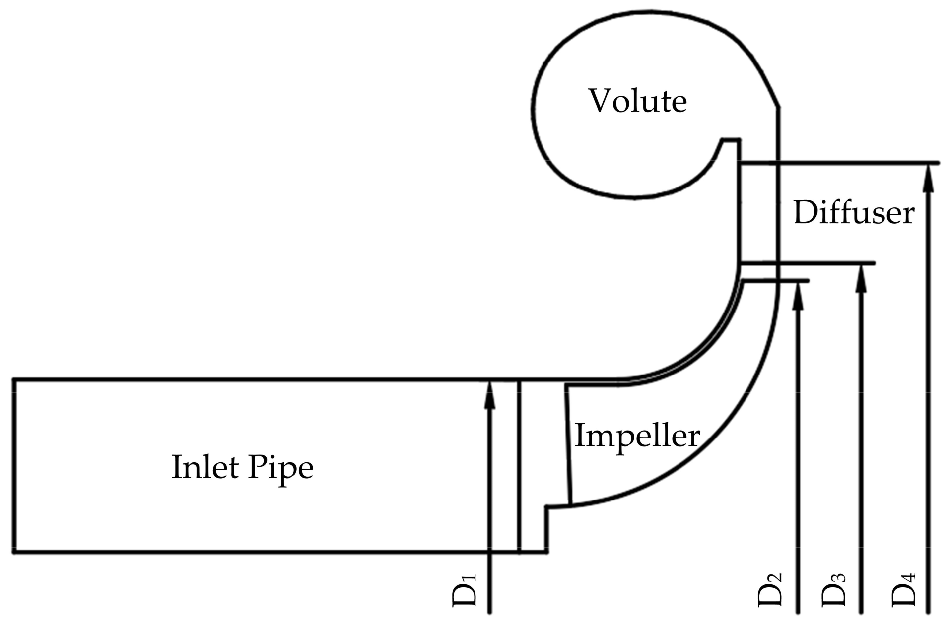
Figure 1. Meridian plane of centrifugal compressor.
Energies 16 03869 g001
Figure 2. Computational domain of centrifugal compressor: (a) inlet pipe; (b) impeller; (c) diffuser; (d) volute.
Energies 16 03869 g002
Figure 3. Mesh of centrifugal compressor main components: (a) mesh of impeller; (b) mesh of vaneless diffuser and volute.
Energies 16 03869 g003
Figure 4. Variation of pressure ratio and efficiency with total mesh number.
Energies 16 03869 g004
Figure 5. Test bench of the centrifugal compressor: (a) arrangement of the test bench: (1) base of the test bench; (2) difference pressure transmitter; (3) double folium flowmeter; (4) inlet pipe; (5) pressure sensor; (6) temperature sensor; (7) host computer; (8) power; (9) centrifugal compressor; (10) pressure sensor; (11) temperature sensor; (12) outlet pipe; (13) regulating valve; (b) schematic diagram of the test bench.
Energies 16 03869 g005
Figure 6. Comparison between simulation and experimental performance.
Energies 16 03869 g006
Figure 7. Computational domain of centrifugal compressors with different inlet pipes: (a) ps; (b) p90; (c) pz.
Energies 16 03869 g007
Figure 8. Centrifugal compressor’s performance with different inlet pipes: (a) 6 × 10⁴ rpm; (b) 8 × 10⁴ rpm; (c) 10 × 104 rpm.
Energies 16 03869 g008
Figure 9. Variation of the total pressure loss coefficient.
Energies 16 03869 g009
Figure 10. Three-dimensional streamlines of the inlet bent pipes: (a) p90; (b) pz.
Energies 16 03869 g010
Figure 11. Streamlines and velocity distribution in three planes: (a) p90; (b) pz.
Energies 16 03869 g011
Figure 12. Streamline and velocity distribution in plane m1: (a) ps; (b) p90; (c) pz.
Energies 16 03869 g012
Figure 13. Dimensionless total pressure distribution in plane m1: (a) ps; (b) p90; (c) pz.
Energies 16 03869 g013
Figure 14. The position of 9 circles selected on plane m1.
Energies 16 03869 g014
Figure 15. Circumferential distortion degree at different circumferences.
Energies 16 03869 g015
Figure 16. Circumferential distortion degree of plane with different inlet elbows.
Energies 16 03869 g016
Figure 17. Variation between PCD and reduction degree of performance: (a) p90; (b) pz.
Energies 16 03869 g017
Figure 18. Variation in the coefficients of performance reduction degree functions: (a) δπ; (b) δη.
Energies 16 03869 g018
Figure 19. Dimensionless total pressure distribution at the inlet of impeller: (a) ps; (b) p90; (c) pz.
Energies 16 03869 g019
Figure 20. Chosen plane at the inlet of impeller: (a) location of m2; (b) rotation direction of the impeller.
Energies 16 03869 g020
Figure 21. Variation of the dimensionless total pressure at the inlet of impeller: (a) ps; (b) p90; (c) pz.
Energies 16 03869 g021
Figure 22. Variation of the axial velocity at the inlet of impeller: (a) ps; (b) p90; (c) pz.
Energies 16 03869 g022
Figure 23. Mass flow rate distribution in different flow passages: (a) ps; (b) p90; (c) pz.
Energies 16 03869 g023
Figure 24. Turbulence kinetic energy distribution at 0.5 times blade height: (a) ps; (b) p90; (c) pz.
Energies 16 03869 g024
Table 1. Main geometric parameters of centrifugal compressor.
ParametersValue
Number of impeller main blades10
Number of impeller splitter blades10
Impeller inlet diameter, D1 (mm)34
Impeller outlet diameter, D2 (mm)75
Tip clearance (mm)0.5
Diffuser inlet diameter, D3 (mm)80
Volute inlet diameter, D4 (mm)111
Table 2. Boundary conditions under different rotational speeds.
Rotational SpeedLocationBoundary Conditions
6 × 10⁴ rpmInlet of the domainPin = 101,325 pa
Outlet of the domainPout = 122–143 kpa (larger flow rate)
Q = 0.033–0.04 kg/s (lower flow rate)
8 × 10⁴ rpmInlet of the domainPin = 101,325 pa
Outlet of the domainPout = 153–185 kpa (larger flow rate)
Q = 0.045–0.049 kg/s (lower flow rate)
10 × 104 rpmInlet of the domainPin = 101,325 pa
Outlet of the domainPout = 205–241 kpa (larger flow rate)
Q = 0.063–0.068 kg/s (lower flow rate)
Table 3. Mesh schemes.
Mesh SchemesImpellerVoluteInlet PipeTotal Element
11,371,900495,973613,3792,481,252
22,197,9803,307,332
33,077,6804,187,032
44,030,2405,139,592
55,261,1006,370,452
66,176,6807,286,032
77,874,3008,983,652
89,174,52010,283,872
910,158,20011,267,552
1011,100,32012,209,672
Table 4. Coefficients of the fitting function between δπ and PCD.
p90-δπabAdjusted R-Square
6 × 104150.0281.1300.998
8 × 104434.8591.4330.993
10 × 1042512.4101.9730.986
pz-δπabAdjusted R-Square
6 × 104137.5371.0160.998
8 × 104242.8321.1870.976
10 × 104635.6821.5050.973
Table 5. Coefficients of the fitting function between δη and PCD.
p90-δηc1c2dAdjusted R-Square
6 × 10⁴−0.6540.807115.2980.984
8 × 10⁴−0.2220.49484.9810.993
10 × 104−0.1500.25377.5100.964
pz-δηc1c2dAdjusted R-Square
6 × 10⁴−2.5172.56972.6000.998
8 × 10⁴−1.3171.66150.6680.998
10 × 104−0.6870.99644.0900.996
Disclaimer/Publisher’s Note: The statements, opinions and data contained in all publications are solely those of the individual author(s) and contributor(s) and not of MDPI and/or the editor(s). MDPI and/or the editor(s) disclaim responsibility for any injury to people or property resulting from any ideas, methods, instructions or products referred to in the content.