Article

Grid-Connected Converters: A Brief Survey of Topologies, Output Filters, Current Control, and Weak Grids Operation

Department of Electrical and Computer Engineering, University of Michigan-Dearborn, Dearborn, MI 48128, USA
*
Authors to whom correspondence should be addressed.
Energies 2023, 16(9), 3611; https://doi.org/10.3390/en16093611
Submission received: 29 November 2022 / Revised: 12 April 2023 / Accepted: 19 April 2023 / Published: 22 April 2023

Abstract

:
Grid-connected converters (GCCs) are used extensively for the integration of DC power sources with AC power sources. However, since it is a complex topic, there are many possibilities for regulating grid-injected currents, as well as different modulation techniques for generating full-bridge PWM voltages. The control techniques are directly related to the type of output filter, as well as to the topology of the converter, since a complex plant can require more sophisticated controllers to keep the system stable, and with good regulation performance. Furthermore, a discussion of the applicability of these converters in weak and very weak grids with high inductance content has recently been growing, which adds a greater degree of complexity to the control structure of the converter. In this brief overview are outlined some topics about topologies, output filters, and control, focusing on the current regulation of grid-connected converters. In addition, a discussion of the main challenges and critical areas in operating on weak and very weak grids is also presented.

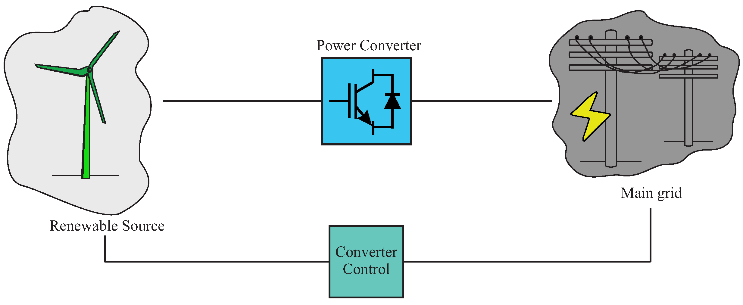
1. Applicability of Grid-Connected Converters

Currently, there is a global effort to replace conventional energy sources based on fossil fuels with renewable energy. This movement is due to the fact that fossil fuels have been classified as being responsible for a large portion of environmental pollution, global warming, and the greenhouse effect [1]. In view of the great growth of renewable energy sources, the need for power converters has also grown, since the conversion of continuous energy into alternating energy is necessary [2,3,4,5,6]. To accomplish this task, a grid-connected converter (GCC) is generally requested [7,8].
The GCCs are used often in renewable energy sources, energy storage systems, and other distributed generation systems with the electrical grid [9]. The grid-connected converters regulate the power flow between the distributed generation system and the electrical grid by controlling the voltage, current, frequency, and waveform of the power injected into the grid. They are also able to provide necessary support to the main grid, such as reactive power compensation and grid stabilization. The importance of GCCs lies in their ability to improve the reliability, efficiency, and flexibility of the power grid, which is crucial for the integration of renewable energy sources and the transition towards a more sustainable energy future [10]. The application of grid-connected converters is quite vast, being used in photovoltaic (PV) generation systems [11,12,13], wind generation systems [14,15,16], distributed generation and microgrids [17,18,19], general renewable energy systems (RESs) [20,21,22], high-voltage DC (HVDC) transmission [23,24,25], and the interconnection between the electrical grid and the process of charging batteries for electromobility [26,27,28].
However, regardless of the application used for grid-connected converters, some parameters need to be defined, such as the topology of the converter to be used, the type of output filter to be implemented, and which control strategy is to be adopted. In addition, it is known that the characteristics of an electrical grid vary according to the location, and this is uncertain. Moreover, impedance-based interaction between an inverter and the grid may cause harmonic resonance in grid currents [29]. Such grid dynamics can severely impact on the control loop of the GCCs, even bringing the whole structure to instability [30,31].
This brief survey paper provides an overview of the recent developments regarding grid-connected DC–AC converters. As renewable energy sources become increasingly prevalent, GCCs are becoming an essential part of modern power systems [32,33]. The main contributions of the paper are:
  • It highlights the importance of understanding the different topologies, output filters, and current control strategies used in these power converters;
  • It also discusses the challenges associated with weak grids operation, and presents possible solutions already discussed in the literature;
  • Its contribution lies in its concise and accessible overview of the field, making it a possible starting point for researchers and engineers seeking to understand or to become updated on the current state-of-the-art regarding GCCs topologies, current control structures, and weak grids operation.
By providing a comprehensive overview of the field, the paper aims to help researchers to identify the main challenges and opportunities for further research topics, and the problems to be addressed in the area.
This work is organized as follows: Section 2 gives a review of the most recent advances regarding grid-connected converter topologies and some specific topics about control. Section 3 discusses the output filter types, their advantages and disadvantages, and the damping methods. Section 4 presents a discussion about the recent discoveries concerning current-control strategies for GCCs. Additionally, Section 5 reviews some critical aspects about grid-connected converters operating under weak and very weak grids. Finally, Section 6 brings the paper to its conclusion.

2. Topologies

The appearance of grid-connected converters is due to the rapid global transformation of the power system, aided by advancements in power electronics and semiconductors [34,35,36,37]. Grid-connected converters are the backbone for integrating renewable energy resources into the grid. GCCs can be understood as one-phase or three-phase devices, using semiconductor power switches to convert energy on the AC side to the DC side, and vice versa, depending upon the application [38,39,40]. GCCs can be connected to both the load side and the source side; this is possible due to their bidirectional power flow capability [41]. The increased penetration of renewable sources, accompanied by GCCs, has changed the traditional grid behavior.
An increased number of devices now employ power electronics. Thus, the future grid tends to be a power electronics interface-dominated weak inertial grid [42]. GCCs feature low inertia, nonlinearity, and multi-time scaling [43], making their dynamic behavior complex. Control schemes such as power sharing capability, frequency control, voltage control, etc., in the converter-dominated grid require special consideration, as the traditional control strategies developed for conventional grids cannot be readily applied [44]. GCCs can easily lose stability in the event of a disturbance, and the fast response of the converter can cause oscillations to develop rapidly [10]. This may lead to voltage and phase changes, which can be hazardous for the whole system [45].
For smooth integration, and to develop an optimized control architecture, a deep understanding of the GCCs’ topologies is mandatory. The need of the day is to develop converter topologies that are flexible, power efficient, and fast, and whose integration can support and strengthen the grid [46,47,48]. Figure 1 shows the interconnection between the grid and the renewable energy source, and the role of the converter.
Apart from the single-phase converters, most of the converters that serve as the interface between the DC and AC sides are three-phase inverters. GCCs are not limited to only a specific renewable source such as solar [38]. They are applicable almost everywhere, such as for wind, tidal, and wave energy, etc. [49]. The generic operating principle of the converters is identical, i.e., to convert DC to AC using fast switching devices. Similarly, AC is converted to DC using the same switches; the difference is in the switching mechanism. Usually, the control is based on the pulse-width modulation technique [50]. The PWM-based technique results in a pulsating-nature output, which is implemented in DC–AC converters by using output filters (this will be discussed in detail in the upcoming sections) [51].
Regarding the power source, DC–AC converters are normally divided into two large groups: current-source inverters (CSIs) and voltage-source inverters (VSIs). CSIs are fed with constant current, while VSIs are fed with constant voltage [52]. In terms of converter commutation methodologies, power converters can be broadly classified into two categories, i.e., natural commutated converters and forced commutated converters [49]. Previously, the line commutated converter (LCC) was considered as the only mature technology, despite its drawbacks in terms of control and efficiency. Commutation failure is the prominent drawback in LCC technology [53] based on thyristors. However, VSC is the trending technology supplanting the far-too-outdated LCC in low- or medium-power applications ranging up to 600 kV [54]. The VSC technology uses IGBTs instead of thyristors, and thus it can be turned on and off with the help of a pulse. It also allows for the independent control of active and reactive power, allowing for the bidirectional flow of energy, which is why it is considered as the most suitable for high-voltage direct current (HVDC) transmission [55]. Multi-terminal direct current (MTDC), combined with VSC, also known as flexible DC technology [56], supports the integration of renewable resources, strengthening the distribution network, power system stability, and the interconnection of the AC system. MTDC is the future of the power system, due to the increasing installations of DC systems worldwide and the flexibility that it offers for the distribution network. The disadvantage associated with using VSC are the power losses due to the presence of diodes [57]. The modular multilevel converter (MMC) covers the defects of VSC, allowing for high power-level operation. It is derived from the VSC in such a way where two half-bridge VSCs are cascaded to form an MMC. The harmonic performance of MMC is better than that of VSC, and is suitable for high-voltage applications. However, the control strategy tends to be complex and time consuming [58].

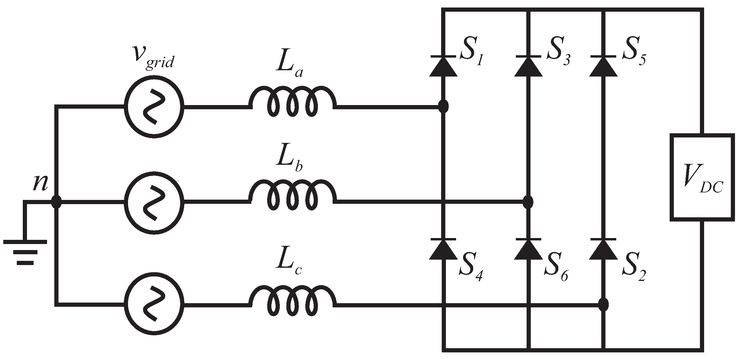
2.1. The Line Commutated Converter

A line commutated current-source converter with mercury-arc valves was used in the first HVDC link commissioned in 1954 [59]. LCCs use thyristors, which can be turned on using a gate signal, and the turn-off occurs at the zero crossing determined by the AC network (line commutation) [60]. The charge stored between the layers of the thyristor during the turn-on period must be removed before establishing the voltage blocking. There must be sufficient recovery time to avoid commutation failure [59]. Figure 2 shows the simplest LCC converter topology.
The LCC configuration normally uses six switches. Two switches conduct in the bridge, connecting and converting the three-phase input to two-terminal DC [61]. For instance, if S1 and S2 are conducting, the output DC voltage is the difference between the phase 1 voltage and the phase 3 voltage. Mathematically, this topology can be represented as
V D C = 3 V L L ( p e a k ) π c o s α 6 f L I ,
where V L L ( p e a k ) is the line-to-line input voltage, and α is the firing angle of the switch. In addition, f is the frequency, L represents inductance, and I is the currrent.

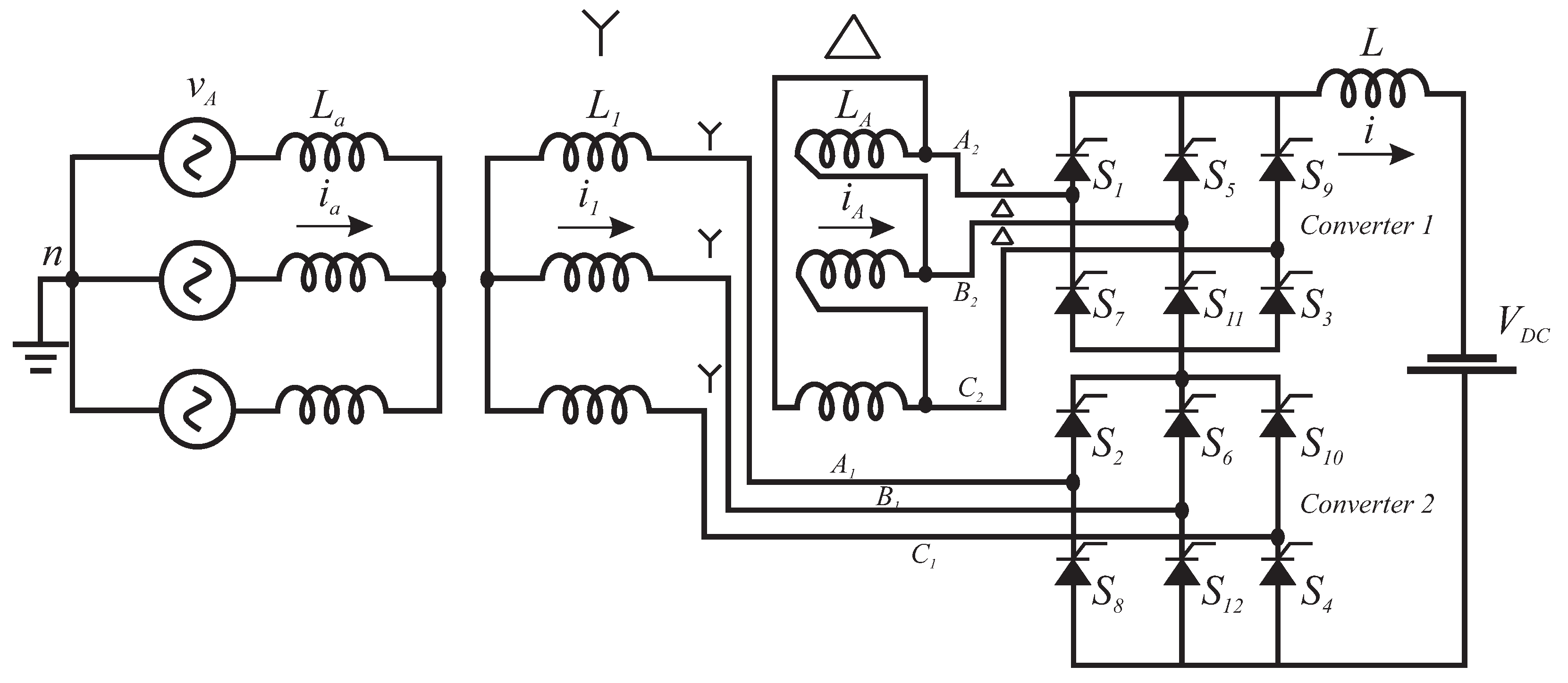
LCC Twelve-Pulse Bridge

The six-pulse configuration leads to significant harmonic distortion at both ends [62]. Thus, large filtering equipment is required, which increases the system’s cost and complexity. The efficient approach is to implement a twelve-pulse bridge. The two bridges are connected in series so that the phase displacement within the AC side results in the cancellation of current and voltage harmonics [63]. The twelve-pulse topology is shown in Figure 3.
The LCC has some limitations because it cannot be seen as part of the modern grid, as the thyristors are semi-controlled devices, and this lack of controllability is a serious disadvantage [64]. It depends on an AC source for its operation and commutation, as the power system is vulnerable to disturbances such as harmonics, voltage, frequency instability, etc. [65]. These phenomena can cause commutation failure, which causes a challenge for LCCs being fed into weak AC grids because they will need a longer time to recover from such disturbances, which can prove hazardous. Moreover, the LCC cannot also control the reactive power [66]. These shortcomings make room for new technology. So, with the advancements in power electronics, the voltage source converter (VSC) was developed, which covers the shortcomings of the LCC technology [67].

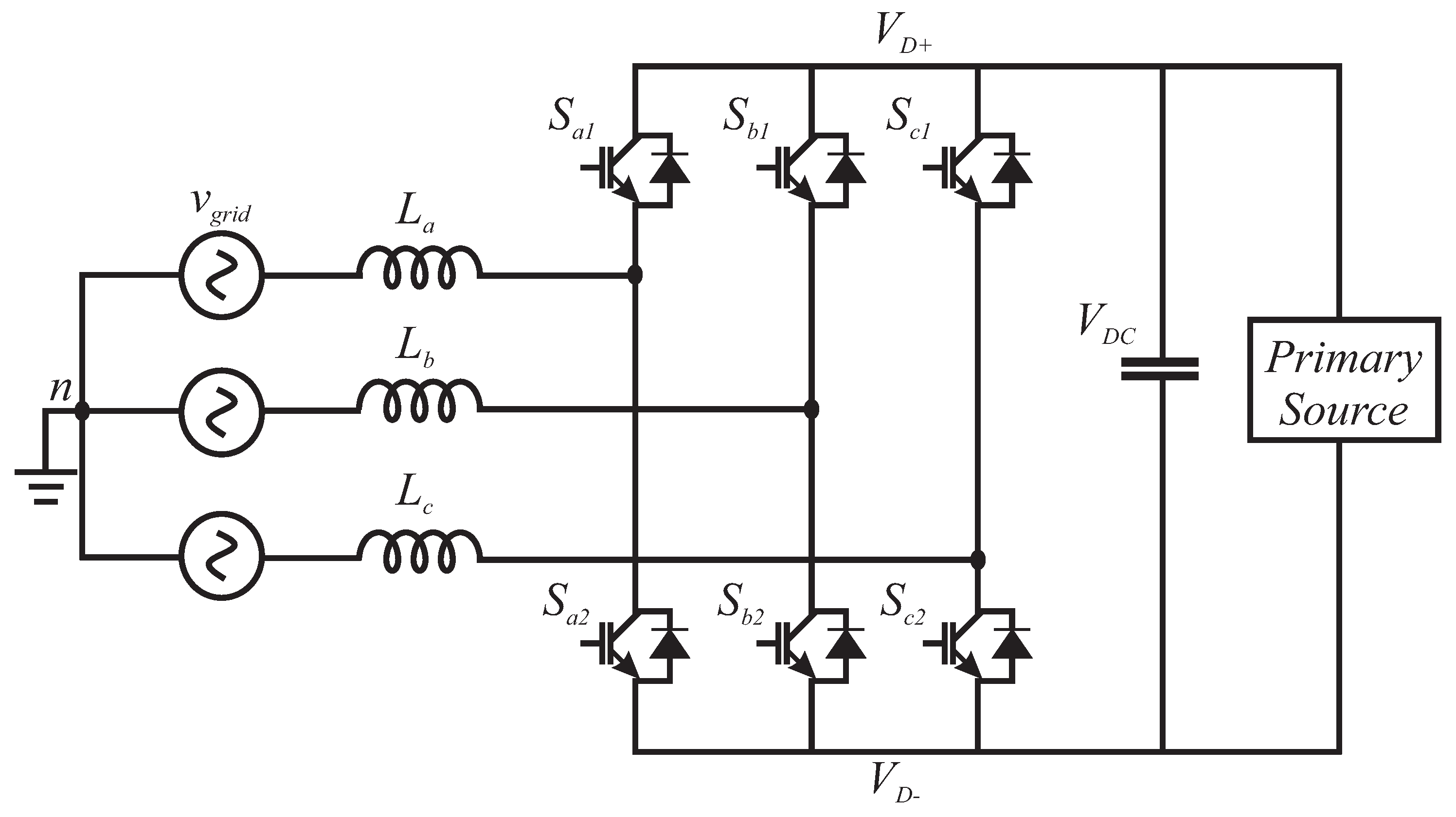
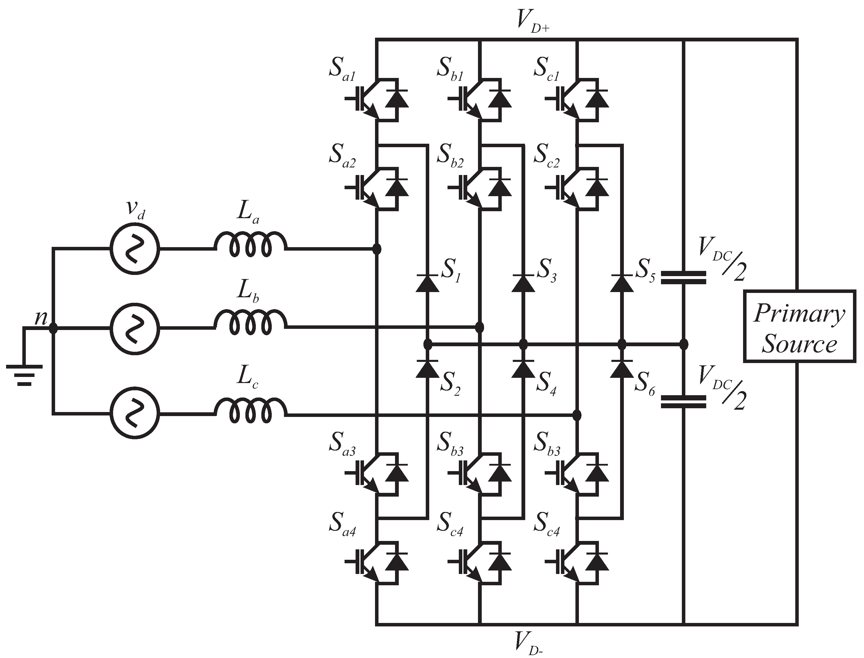
2.2. The Voltage Source Converter

The insulated gate bipolar transistor (IGBT) provides two-degree freedom, i.e., the capability to turn off and on, which forms the basis of a voltage source converter. A VSC is a converter that can convert AC to DC or DC to AC [68]. In a VSC, the polarity of the voltage remains constant, and the direction of the power flow is determined by the direction of the current. A large capacitor is connected in parallel to the VSC, as it relies on a stiff DC voltage source, which implies approximately constant DC voltage between consecutive switchings. In practice, a large capacitor is required at the DC side of the VSC converter. DC capacitance is used for flicker mitigation [69,70]. The full controllability improves the low-order harmonic performance of the converter because IGBTs can be turned on and off according to requirements, simply through a pulse [71]. This was not possible in an LCC. Unlike the LCC, VSCs have the ability to rapidly control the transmitted active power, and also to independently exchange reactive power with transmission systems [72]. The comparison of both technologies is presented in Table 1. The structure or working principle of a VSC can be comprehended by understanding the structure of an H-bridge. Figure 4 represents a two-level, three-phase VSC. The parallel diode attached to each IGBT allows for conduction in the reverse direction, creating a bidirectional switch.
The simplest two-level VSC without good PWM-based control can result in harmonics and distortions as compared with the high-level VSCs or a VSC with a good PWM-based control. The pulse-width modulation technique is used to improve performance by decreasing the harmonic distortion [73]. The PWM technique allows for the switching of the IGBTs at a rapid rate. However, such frequent switching results in power losses during the switching, reducing efficiency [74]. A two-level VSC is not suitable for very high voltage levels because it is necessary to connect a large number of IGBTs in series, followed by the gate-driving circuit of each IGBT. This will increase the complexity of the circuit and result in increased levels of electromagnetic interference [75]. To improve the harmonic performance of a two-level VSC, another configuration known as a three-level or neutral-point clamp (NPC) converter may be used [76]. The NPC converter can synthesize three levels of voltages at the AC terminal. The NPC topology is shown in Figure 5.
Several strategies can be applied for the control of a VSC, but the most common strategy is the vector control method. Multiple control strategies for the VSC can be found in the literature; for instance, in [77], a fuzzy logic technique was implemented to optimize the performance of a VSC. A deep learning approach was adopted in [78]. A droop control strategy was applied in [79]. The scope of this section is focused toward the understanding of the circuit topology, and further control techniques will be discussed in detail at Section 4. Using IGBTs, a vector control method can be applied, which results in the independent control of active and reactive power, supported by the bi-directional power flow capability of the converter. The AC currents and voltages inside the converter following the vector control strategy are converted in a direct-quadrature (d-q) frame of reference. During the conversion from abc to d-q reference, the angle is kept synchronized with the help of a phase-locked loop (PLL) [80,81,82]. The vector control architecture of a VSC is shown in Figure 6.
To better understand the control architecture, it can be viewed as a two-level control system, composed of an inner loop (low-level control) and an outer loop (upper-level control). The inner loop regulates the d q components of the current through the filter and the coupling. The outer loop deals with the active power and magnitude of the voltage. Based on the vector current control, the lower-level structure includes a PI controller to regulate the current through the inductor. In addition, the independent control of the d and q axis is also allowed [83], providing the extended mathematical details and the vector current control concept. The outer loop calculates the current reference to obtain the desired active power value and voltage amplitude. It consists of two PI controllers, one for each component.
Regarding the converter topology, it is called a two-level VSC because the voltage on the AC side will be either ( V D C ) or ( + V D C ) . The common DC side voltage source is in parallel with the half bridge’s DC side, while the AC side of each half bridge is connected to one leg of the three-phase AC side [84]. Mathematically, the VSC can be modeled as
V ( t ) = m ( t ) V D C 2 i ( t ) | i ( t ) | V e r e i ( t ) ,
where V e and r e are defined as
V e = V d ( Q r r + Q t c T s ) r o n + V D C ( t r r T s ) ,
r e = ( 1 t r r T s ) r o n r o n ,
and T s is the switching time period of the converter.
The interaction of the VSC system with the grid can be classified into the following categories:
  • Grid Imposed Frequency VSC System: VSC is interfaced with a large AC system; hence, the operating frequency is led by the large system [85].
  • Controlled Frequency VSC System: The VSC and the AC grid are connected in such a way where the VSC regulates the overall frequency [86].
  • Variable Frequency VSC System: In the variable system, the operating frequency is not regulated directly but instead is treated as an overall system state variable, depending upon the operating point [87,88].
Table 1. LCC vs. VSC Performance Comparison [54].
LCC and VSC Performance Comparison
PropertyLCCVSC
CommutationRequires AC waveform for commutationDoes not need AC waveform for commutation
System CostHigher cost—requires filtering equipmentLow cost, low filtering requirements
Power FactorNeeds reactive power supplyLow cost, active and reactive power controls
HarmonicsHigh harmonicsLow harmonics
System CostHigher cost—requires filtering equipmentLow cost, low filtering requirements
Power FlowVoltage polarity needs to be reversedBi-directional current flow
Voltage and Power LevelHigh voltage/power level—800 KVLow voltage/power level—500 KV
Energy Storage ElementInductorCapacitor
Overload CapabilityGoodWeak
P and Q ControlDependent P and Q controlIndependent P and Q control

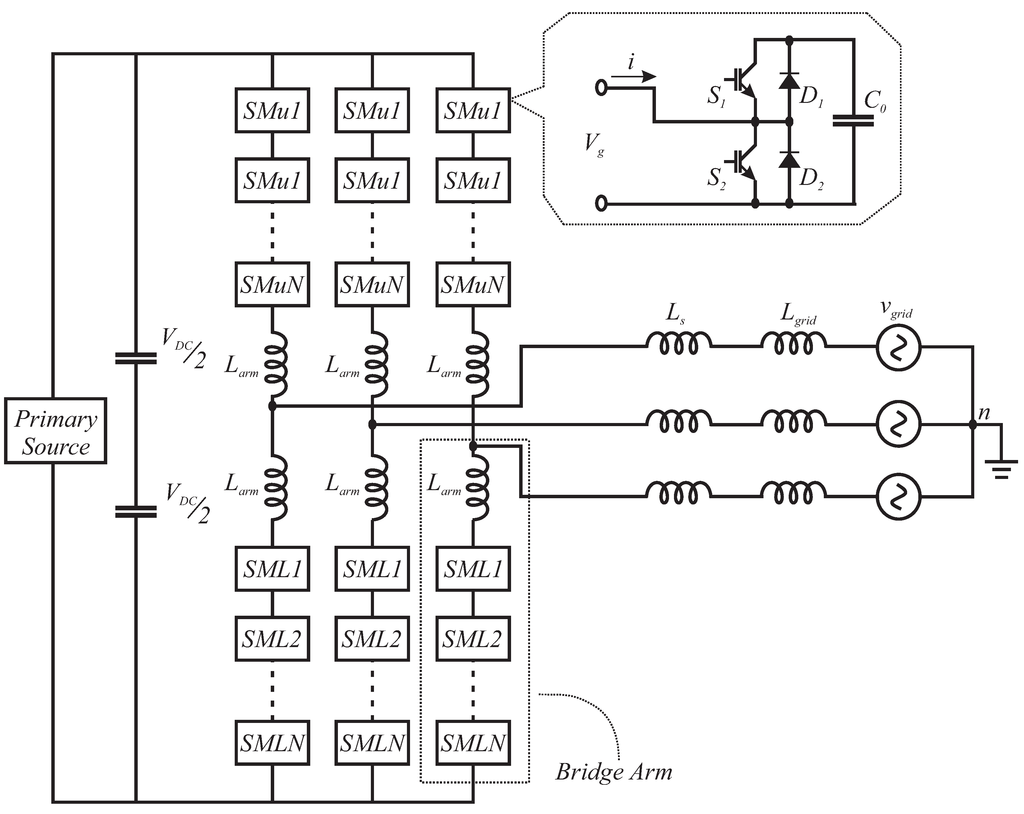
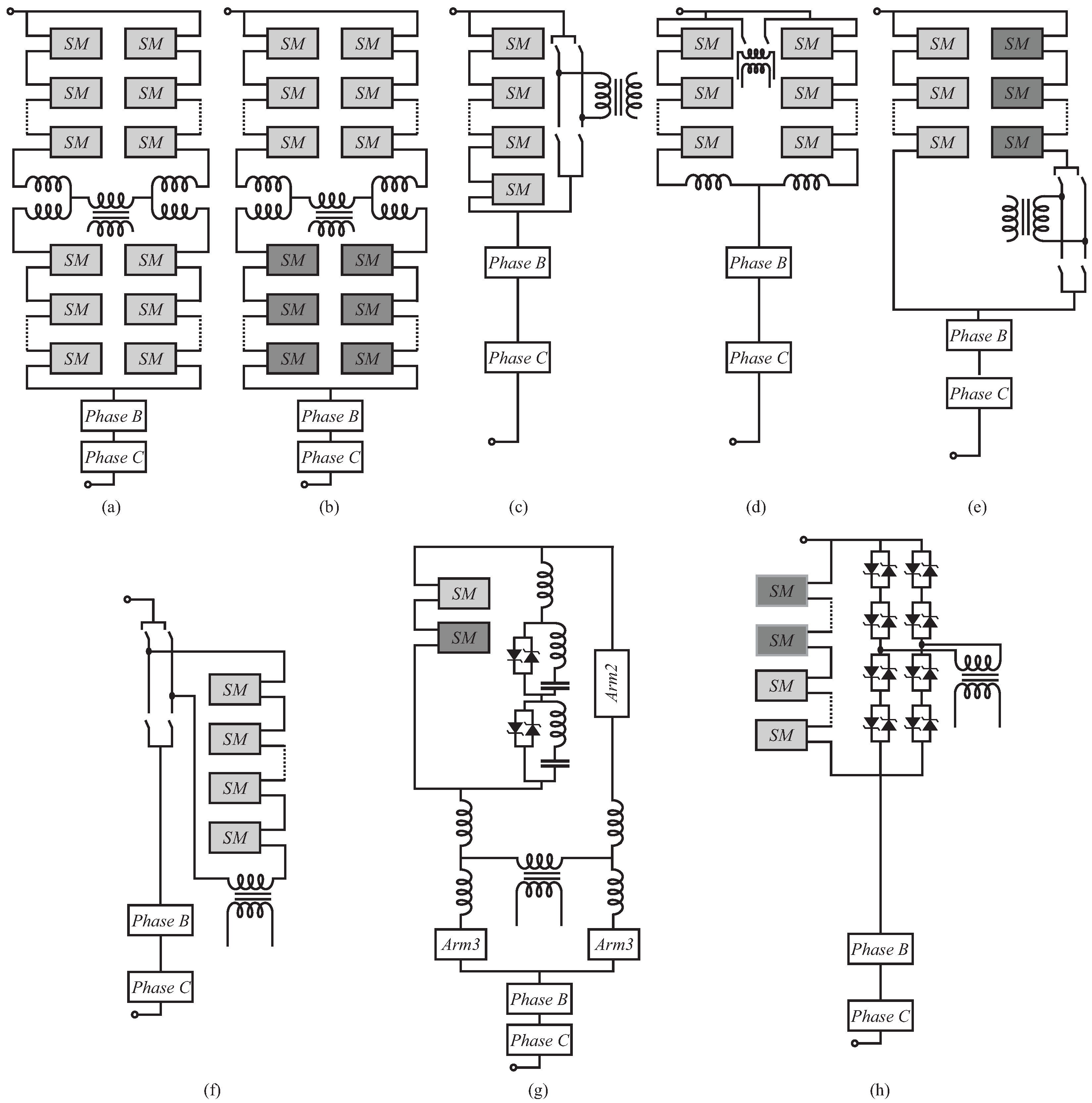
2.3. The Modular Multilevel Converter

The modern power system infrastructure, dominated by renewable or power electronics-interfaced sources, requires synchronous and asynchronous interconnections [89]. Most of the renewable energy generation units are located far from the demand centers, so the efficient transmission of electricity over such a long distance is always a challenge in terms of power losses [90].
As discussed in the previous section, the VSC is more efficient than the LCC technology, but VSC still has some limitations and a lot of room for improvement. Therefore, the modular multilevel converter (MMC) topology was realized recently, and it has been identified as the most efficient transmission technology to date, as compared with the VSC or any other converter topologies [91,92,93]. Compared with other topologies, the MMC offers unique advantages such as high efficiency, ease of scalability, good THD performance, fault tolerance and blocking capability, reduced voltage stress on switches, etc. [94,95]. Moreover, due to the modular structure of the MMC, the voltage stress across each switch is divided, and so low-power switches can be used for overall high-voltage conversion applications. The MMC is becoming a building block for the new renewable energy installations and MTDC projects [96,97]. Figure 7 shows the structure of MMC topology.
The structure of the MMC is such that each phase has two arms, i.e, an upper arm and a lower arm, connected through an inductor. The inductor plays a role in limiting the circulating currents, and during fault protection. Each arm contains “n” number of sub-modules (SMs); in total, there are “2n” SMs (upper arm and lower arm) [98]. Each SM is usually a half-bridge with two switches and one parallel capacitor. It operates in such a way where at each instant of time, “n” SMs are ON (including the upper and the lower arm). Inside the SM, when the upper switch turns ON, the voltage appears across the capacitor, while the capacitor is bypassed when the lower switch turns ON [99,100]. This creates a staircase waveform at the output whose levels depends on the number of SMs in the entire string m = n + 1 . This sub-modular structure allows the converter flexibility for medium- and high-power applications. The MMC most certainly offers advantages, but its control needs careful consideration. Additional control schemes for balancing the capacitor voltage are required, due to which the resultant system becomes complex and expensive [101].
The optimized MMC performance can be leveraged by applying proper DC voltage and AC-side control. The MMC’s capability enhances the system stability and provides support to the AC side. The outer and inner loop control strategies developed for the VSC can be extended for the MMC. In the literature, several control schemes for balancing the voltage of the DC capacitors are illustrated [102,103,104]. Apart from the significant advantages that the MMC technology provides, it also has some challenges that need to be resolved, such as large energy storage requirements in the DC capacitor, the requirement for a large number of semiconductors, the circulating current problem, fault handling, etc. [105,106,107,108,109]. These issues are still a hot research area and can be overcome through the modification of either the converter structure or the control method. Some extended MMC topologies can be found in the literature, but there is no comprehensive overview of the existing extended MMC topologies. This paper covers all the advanced and extended MMC topologies. In Figure 7, the half-bridge SM MMC toplogy is shown, which is a very popular one controlled by controlling the two switches in the SM. The control and modulation scheme decides the number of SMs to be inserted into each arm. Usually, the PWM-based mature modulation techniques are applied due to their ease of implementation and good performance [110].
Table 2 shows the performance analysis in terms of the benefits and shortcomings of the MMC.

2.3.1. Parallel-Connected MMC Topologies

One of the most common extended MMC configurations is the parallel-connected converter configuration. In this arrangement, each phase has to support the DC voltage. These parallel-connected topologies include the alternate arm converter, the H-bridge-based converter, three-level converters, etc. The alternate arm converter combines the benefits of the MMC and the two-level converter [112,113,114]. This topology leads to the minimum number of SMs, along with fault ride-through capability. The energy storage requirements for the SMs are low here due to the fact that energy deviations are smaller as compared to the normal MMC topology [115,116]. Figure 8 illustrates the parallel-connected MMC topologies, showing the short overlap [117], extended overlap [118], shared alternate arm [119], improved alternate arm [119], and augmented trapezoidal arm [120] topologies, respectively.

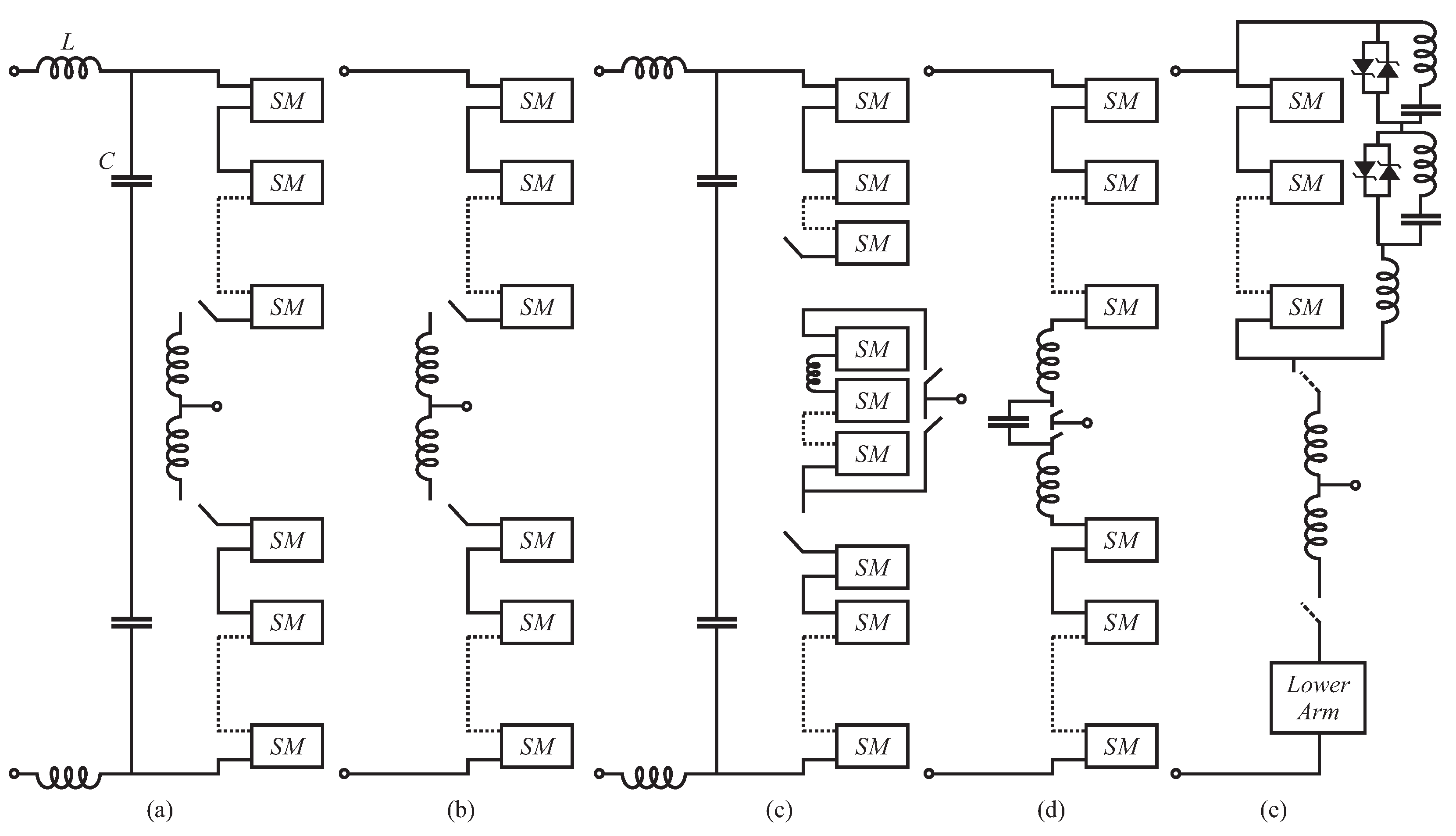
2.3.2. Series-Connected MMC Topologies

Unlike parallel-connected MMCs, series-connected MMCs are meant for low-power applications. In the series-connected configuration, each phase is exposed to one-third of the full voltage with full current flow. The SMs are connected with an arm inductor in series for each phase [116,121]. Moreover, due to the lower number of SMs required, the power losses are also relatively low compared with the simple MMC. The disadvantage of the series connection configuration includes the third harmonic current issue caused due to the single-phase structure [122]. Under faults or unbalanced grid conditions, the DC voltages need to be balanced. Figure 9 shows multiple series-connected topologies, such as series-connected MMC [121], series-connected asymmetrical hybrid MMC [123], series hybrid multilevel converter [124], modular directed series modular converter [125], and series bridge converter [126].

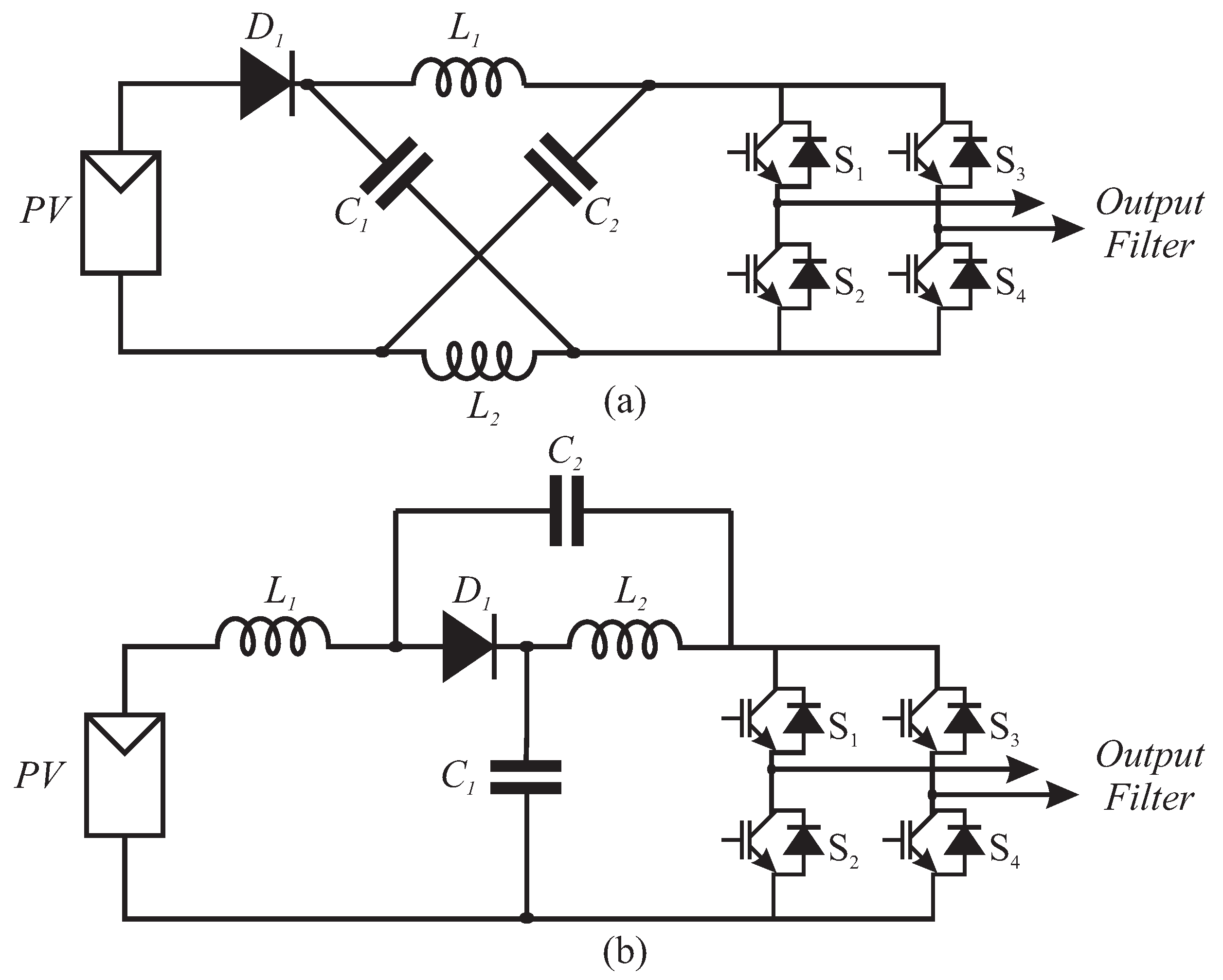
2.4. Z-Source and Quasi-Z-Source Topologies

Different from voltage-source and current-source converters, there are the impedance-source (or Z-source) converters. The Z-source inverter (ZSI) was proposed initially by [127]. It employs a unique impedance network to couple the converter main circuit to the power source, load, or another converter for providing unique features that cannot be observed in the traditional voltage-source or current-source converters. The unique feature of the Z-source inverter is to operate as a buck–boost inverter that has a wide range of obtainable voltages [127].
The Z-source converter also generated another converter topology, the quasi-z-source inverter (qZSI), widely used in distributed generation applications [128]. The qZSI has certain additional features: it draws a constant current from the generation source and presents less stress on the impedance source components, making this topology quite suitable for applications in photovoltaic systems, as shown in [129,130,131]. Figure 10 presents the Z-source and quasi-Z-source single-phase converter schematics, where L 1 , L 2 , C 1 , and C 2 constitute the impedance network.
Both the ZSI and qZSI have passive elements between the input source and the inverter bridge, allowing for the use of a third operating state in addition to the status of power transfer from the bus to the output and the status of freewheel, which is the shoot-through state (ST). This is possible because the bus impedance network limits current growth in the short circuit state, as shown in [129]. With the availability of this third state, input voltage regulation of the photovoltaic array can be performed, such as the sum of the voltages on the impedance source capacitors or the voltage on just one of them. Additionally, if considering a cascade loop, the waveform of the current injected into the grid can be adjusted, as shown in [130,132]. Despite the advantages of the impedance network, the inclusion of inductors and capacitors increases the order of the converter models. To reduce the effort and order of the models, the vast majority of works that use the qZSI topology model the photovoltaic array as a voltage source (Thevenin equivalent) [127,130].
However, in view of the nonlinearity of a photovoltaic module, it is known that the intrinsic input resistance varies according to the irradiation and temperature, as shown in [133], revealing itself as an uncertainty in a PV system. Furthermore, in view of the need to track the maximum power point using an algorithm such as perturb and observe (P&O), it is necessary to regulate the current or the voltage of the PV array, which requires the inclusion of a third capacitor in the model. This capacitor is placed in parallel with the PV array and allows the converter input voltage to be modeled as a state of the system. On the other hand, some models obtained using this method pass from second and fourth order to fifth order, reasonably increasing the complexity of the controller design [130].
Several control techniques were used for the regulation of impedance source converters. Ref. [130] proposed the application of PI and PR to control the capacitor voltage and grid-injected current, respectively. In addition, Ref. [134] proposed an SM control structure, while Ref. [135] proposed the application of an adaptive controller for the regulation of the equivalent bus voltage. Recently, model predictive control structures were proposed for the regulation of closed loops in quasi-Z-source converter applications [136,137].

2.5. Section Discussion

Up-to-date and advanced grid-connected converter topologies were discussed and presented. Every topology has a set of advantages and disadvantages, which were presented so that the reader can opt for the correct one according to the application. Moreover, a brief overview, comparison, and some control architectures of recent and advanced GCC topologies from the literature were discussed, which will help to pave the way to present the solved issues, as well as the research challenges in this domain of power electronics.

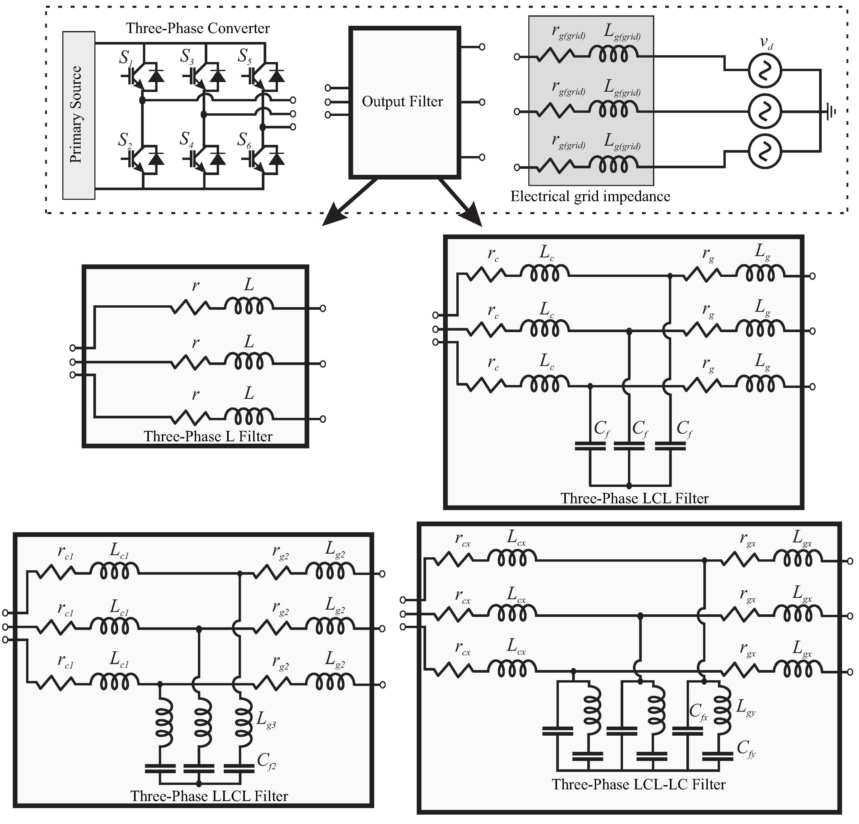
3. Output Filters for GCCs

To carry out the integration of renewable energy sources with the grid, especially when it comes to photovoltaic solar energy, output filters are considered in order to reduce the high-frequency harmonic components generated by the switching action of the converter. There are well-known standards that impose some restrictions regarding energy quality, such as IEEE 519, IEEE 1547, and IEC 62109, which limit the total harmonic distortion (THD) rates of grid-side currents up to 5%, and also give directions about individual harmonics limits. Several types of output filters were considered for GCC harmonics suppression, such as L, LCL, LLCL, and LCL-LC [138,139,140,141,142]. Figure 11 shows a three-phase grid-connected converter with different output filter settings.
Although each filter configuration has positive points, the most common filters for grid-connected converters are the L and LCL. Note that the L filter, being of the first order, presents an attenuation of −20 dB/decade, while the LCL filter, of the third order, presents an attenuation of −60 dB/decade. In addition to the greater suppression of harmonics at high frequency, the LCL filter tends to present a smaller size and weight, and reduces the cost of the converter project [140,143,144,145]. On the other hand, in terms of modeling, design, and control challenges, the LCL filter proves to be more complex than the L filter [20,22,143], since the LCL tends to present a significant resonance peak, bringing a higher degree of difficulty to the control algorithm [20,21,22]. To attenuate the resonance peak present in the output filters, there are two main approaches: passive and active damping, which will be discussed next.

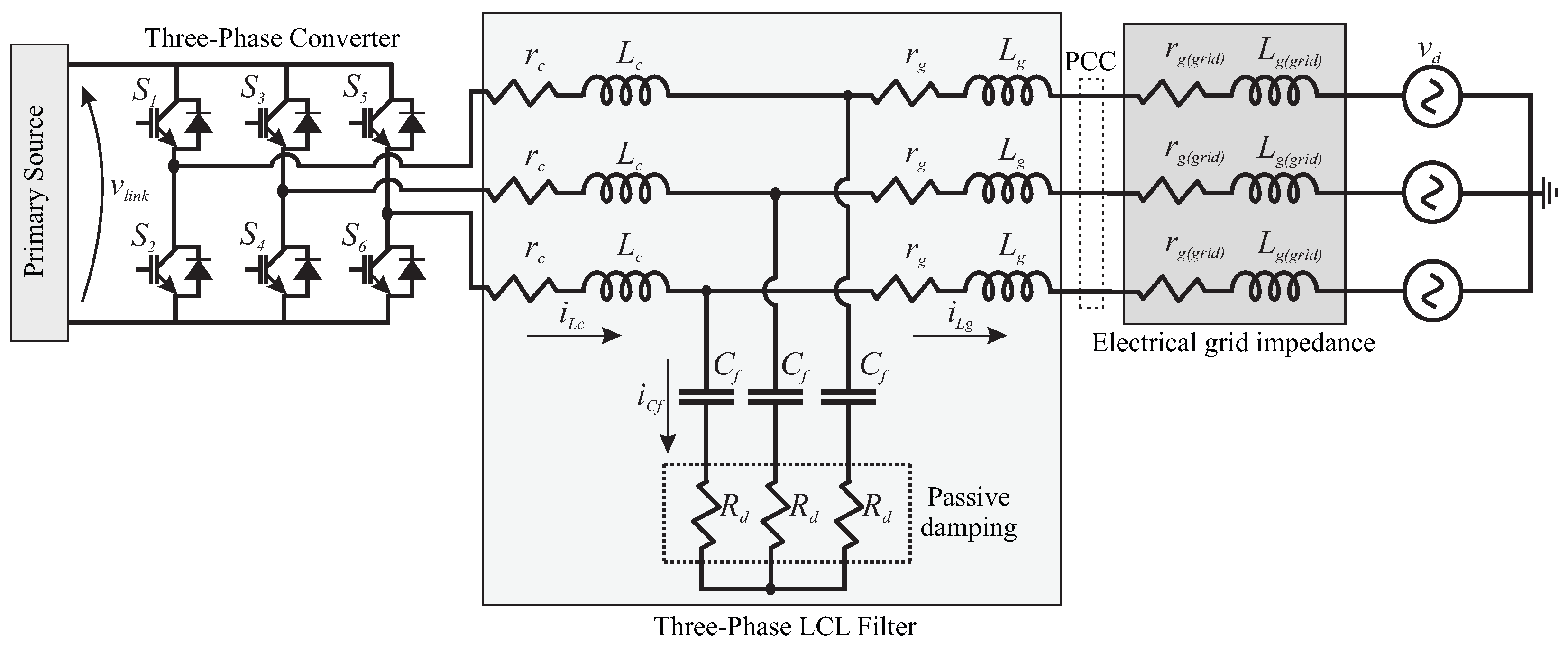
3.1. Passive Damping

Passive damping is performed via hardware, where other elements are added to the system filter in order to reduce the resonance peak of the filter. For the LCL filter, for example, the most common is the insertion of a resistor in series with the filter capacitor, since this element has less current circulation, and consequently the efficiency of the system tends to be less impaired, as there is less power dissipation in the form of heat [146]. Moreover, Ref. [147] contributes with a comprehensive analysis of designing a passive LCL filter for the shunt active filter, modulated by using variable switching frequency techniques. In this work, the designed parameters of the LCL filter affect the improvement of the efficiency of the active filter considerably, and lower the ratings of the power switches. However, other techniques of passive damping were proposed, such as inserting a resistor and a capacitor in parallel with the LCL filter capacitor [148], which generated a margin for studies on the losses obtained with different forms of passive damping [149].
Nevertheless, it is noted that this is a research topic that has not attracted much recent attention from researchers, since with the growing concern about system efficiency, especially when it comes to renewable energy sources, passive damping techniques have given way to active damping techniques. This has occurred because nowadays the computational powers of microcontrollers and digital signal processors (DSPs) are quite high. Thus, it is justifiable to choose complex active damping techniques, which require a complex design and an elevated computational effort from the controller, since execution speed and computational memory for the application of real-time controllers is less and less of an issue.

3.2. Active Damping

In a different way, active damping is normally performed by the control system via software, but even if there is no reduction in the system’s efficiency, the complexity of the control structure tends to be impacted [150,151,152]. This technique has gained a lot of visibility over the last few years, and several works have emerged along this line, as in [20,21,51,143,153,154,155,156,157,158,159,160,161,162].
In [153,154], active damping techniques based on virtual impedance are investigated, where a proportional gain is implemented in the control loop, emulating the physical resistance of the LCL filter. Moreover, a similar approach can be developed in which the proportional gain can also be changed to a high-pass filter in order to mitigate the effect of time delay and maintain resonance damping [155]. In addition, Ref. [156] presents a comparative analysis of a virtual resistor damping technique applied to LCL filters.
A different approach is proposed in Ref. [143], where a design procedure enables LCL filters to obtain enhanced stability and robustness based on selecting the ratios between the switching and resonance frequencies, the electrical grid and converter inductance, and the filter capacitance and total inductance. Moreover, the LCL filter parameters are obtained by selecting the proper ratios, the attenuation, the desired robustness, and the reactive power consumption. In addition, Ref. [161] presented a new active damping method, where a solution for improving the conventional direct power control (DPC) was presented. This method aimed to improve the conventional DPC with an active damping algorithm via multivariable constraint adjustment, which is based on an augmented lookup table and multivariable comparators.
It is known that adaptive controllers can be implemented for the regulation of plants over a simplified mathematical model, since some assumptions and restrictions can be expected, as widely discussed in [163,164]. In this way, a different way for the active damping of LCL filters based on direct-type adaptive controllers was recently proposed by [158] and also implemented in [20,21,22]. This technique aims to use a direct-type adaptive control algorithm with a reduced-order reference model. Then, the LCL filter can be mathematically considered as a first-order model, where the pair of conjugated complex poles referring to the resonance peak can be disregarded, since it is located at a frequency that is much higher than the frequency of the signal of interest. However, this technique can be implemented only by control algorithms that are sufficiently robust against matched and unmatched dynamics.

3.3. Section Discussion

Finally, it can be seen that there are several possible filter configurations for GCCs. Each type of filter has its own characteristics; however, it can be seen that as the filter order increases, and consequently, its high-frequency harmonic attenuation performance increases, the effort required by the control structure to keep the plant stable and with good regulation performance is high. In addition, regarding the damping of the resonance peak of higher-order filters, it appears that several works have been developed for both passive and active damping, showing that both techniques are possible for implementation for commercial applicability. However, the choice of the converter topology, as well as the need for an output filter and the damping technique (if necessary), varies according to the application and must be determined on a case-by-case basis.

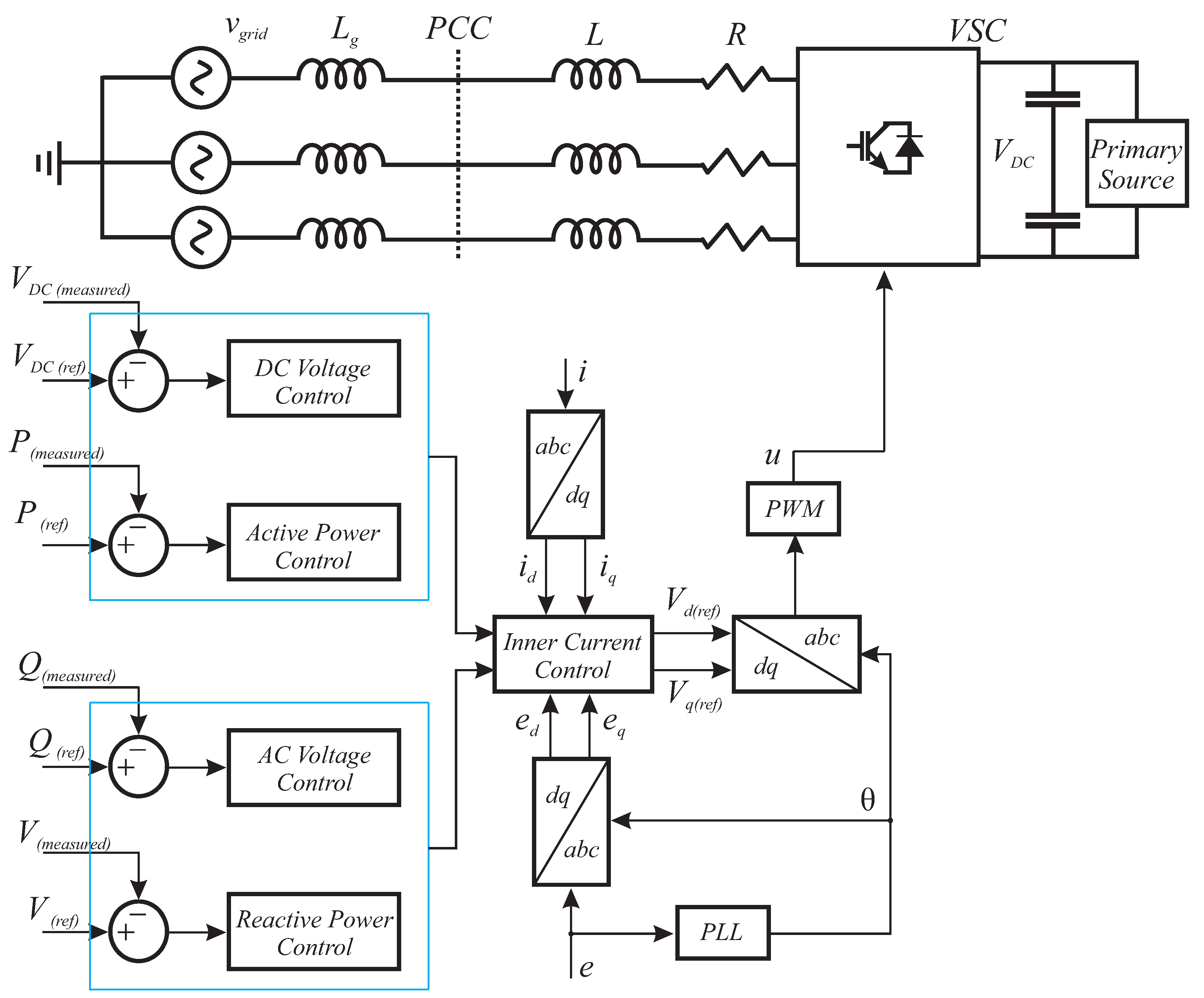
4. Current Control of GCCs

For DC–AC power converters, the regulation of the output current is essential for correct operation. Depending on the application, it is still common to control the DC bus voltage or even the voltage level of some specific capacitors that make up the DC bus [131]. When the topic is regarding complex DC–AC topologies, such as Z-source or quasi-Z-source converters, the control structures can be severely complex [165,166]. In solar photovoltaic applications, for example, it is also common to regulate the maximum power point tracking (MPPT) of the system [167]. However, given the wide range of topologies, applications, and control structures, this section aims to address recent discoveries regarding the current control of GCCs. It is common for GCCs to have two kinds of control regulation: converter-side or grid-side. Although converter-side current feedback controllers are simpler than grid-side current feedback controllers, they cannot ensure a precise injection of active power because they present phase differences when compared with the grid-side current. In contrast, grid-side current feedback controllers can perform it. However, it is more complicated for the control structure to regulate the grid-side currents than the converter-side currents, since the plant for converter-side current regulation presents a relative degree of 1 (phase lag = 90 degrees), while the grid-side current presents a relative degree of 3 (phase lag = 270 degrees) [21,51].
In addition, as previously discussed, the most common output filters for DC–AC converters are L and LCL filters. L filters are first-order systems, while LCL filters are third-order systems and their control is far more complex than that of L filters due to a pair of conjugated complex poles (resonance peak) [22,51,168,169]. Furthermore, the techniques designed for LCL filters can also be applied to L filters, but since their level of complexity is not elevated, they commonly do not demand complicated control structures. In this way, PI or P + R controllers are widely used for GCCs with L or LC filters [170,171,172,173,174].
On the other hand, when the topic concerns GCCs with LCL filters, it is possible to have P + R controllers for the current-control loop, as discussed in [175,176,177]. However, this technique has been losing space for more robust techniques over the past few years. There are high-performance controllers, based on the feedback of the converter-side or grid-side currents aiming at fast transient response, low grid-currents’ THD, and elevated robustness [21,51,178,179]. When we discuss grid-connecting converters, there are many different uncertainties, such as load uncertainty and abrupt variation, grid impedance uncertainty and variation, exogenous disturbances, parametric variations due to modeling approximations, sensor error, and even the aging of the converter components, which tends to impact on the components’ value [8,158]. Therefore, when one or several of these uncertainties stand out, the global stability of the closed-loop system can be compromised, since the plant model can be considerably different from that obtained under adequate operating conditions, requiring more robustness from the control structure [21,22]. In light of this, several different control strategies were designed, being aimed at robustness with reasonable performance, such as robust controllers, predictive controllers, and adaptive controllers, among other techniques that will be discussed next.
Robust controllers can deal with uncertainties by maintaining stability with reasonable performance due to the polytopic time-varying model considered in the controller design [180,181,182]. For GCCs with LCL filters, sudden variations can affect the resonance peak, shifting the filter resonance peak and impacting the current-control loop. This behavior can occur due to an increase in grid impedance (regarding a weak or very weak grid) or else due to severe parametric variations in the plant, as previously discussed. In this way, system stability may not be assured [183], once it is assumed that the plant is linear and deterministic [184]. Furthermore, robust controllers are usually designed using linear matrix inequalities (LMIs). However, the LMI design is far from trivial, and full-state feedback requires a large set of sensors for implementation in practical applications [178,185], which tends to severely impact upon the project cost and hardware complexity. To overcome this problem, some techniques considering partial-state feedback for GCCs were proposed in the literature, aiming to reduce the number of sensors while maintaining good performance and high robustness [186,187].
Another common branch of controllers for the current control of GCCs is based on sliding mode control (SMC), and was applied in single-phase and three-phase GCCs, as in [8,179,188,189]. SMC structures can provide relevant robustness due to their independence from the plant parameters [190,191,192]. On the other hand, due to its nature, the SMC controller will tend to present high-frequency oscillations (chattering). These oscillations are related to the order, and consequently, to the complexity of the sliding mode structure, as well as to the sampling frequency and also to the parametric variations of the plant [193,194]. Considering this, low-order, SMC-based control strategies need additional algorithms to mitigate the chattering effects [194] once the chattering phenomenon tends to increase the overall currents’ THD [8,179,188], which directly impacts on the system energy quality. In contrast, high-order SMC can naturally attenuate the chattering phenomenon [191,195,196]. However, this performance enhancement comes in exchange for an increase in controller mathematical modeling and computational burden.
Model predictive control (MPC) is commonly used in many industrial applications, including for the current control of GCCs [166,197,198,199]. This kind of control structure requires the knowledge of an accurate plant model to determine controller gains in order to obtain satisfactory performance results with acceptable robustness. However, since this control method requires a precise model of the plant, potential variations in the system parameters, such as unmodeled dynamics and parametric variations that were not considered when modeling the system, can affect the closed-loop performance and stability. Hence, some solutions were carried out in order to bypass this limitation by including a model reference adaptive system (MRAS) [200], robust deadbeat predictive control [201], or a Luenberger observer [202], among others. In addition, optimization techniques were also applied to overcome parameter discrepancies, such as LMIs [203], stochastic algorithms [204], and others. Model predictive structures can also be implemented when the system is lacking state measurements, and can be considered in order to reduce the number of sensors, and consequently, to impact on the system cost. Some alternatives include state estimators, as proposed in [205,206,207].
As can be noted from the control structures discussed, a common limitation among the control algorithms is the lack of updating the controller gains in real time. Since the controllers are designed to perform within a specific zone of operation, considering parametric variations and limited disturbances in the plant, if the system to be controlled is subjected to severe disturbances or unmodeled dynamics, the stability of the structure can be compromised and the controller will not be able to regulate the plant [21,178]. Several alternatives have been proposed in order to correct this limitation, using learning-based controllers to modify the gains online, or at least to predict the abnormal plant behavior, as in [208,209,210,211]. However, intelligent learning-based algorithms, such as machine learning and deep learning techniques, tend to require a large dataset in order to train the neural networks, since they need to understand the behavior of the system in the face of the most diverse scenarios and uncertainties, in order to propose gains updates and corrections in the real-time control algorithm [211,212]. However, for implementation in commercial DSPs to regulate industrial applications, such as machines, converters, or active filters in environments with several unmodeled dynamics, for example, the use of these techniques based on real-time learning and control application in real time is unfeasible. Furthermore, for control of machines or converters connected to the grid; for example, where the sampling frequency varies from around a few kHz to dozens of kHz [21,51,213], online learning-based techniques are impractical, since new gains are expected from the control system at each operating cycle. Due to this limitation, the union of techniques based on learning for tuning controllers in real applications usually presents simulation, hardware in the loop (HIL) or control in the loop (CIL) results [209,212,214,215], or intelligent offline decision making [211,216], since due to hardware limitations, it is not possible to apply the complete algorithms (learning-based algorithm + control algorithm) in real time.
On the other hand, optimization techniques were applied offline in order to find the best control structure gains for real applications [187,217,218,219,220,221,222]. Since these optimization algorithms are implemented offline, where the optimization technique tends to converge to the best solution set of gains to minimize a cost function chosen by the designer, it does not tend to impact relevantly on the computational burden [219,220]. However, it is important to guarantee the stability of the control structure in the face of the set of gains obtained using the optimization algorithm, since for real applications, there are hardware limitations that cannot be considered in simulation. There are several different algorithms for the optimization of control structures, such as the genetic algorithm for PI controllers [223], dolphin echolocation for neural PID controllers [224], the spider monkey optimization algorithm for PV systems [225], the artificial bee colony algorithm for PID controllers for power converters [226], the ant colony optimization algorithm for PID controllers [227], and particle swarm optimization for GCCs with LCL filters [228], as well as genetic algorithms applied for the optimal initialization of direct-type adaptive controllers for GCCs [221,222], among others.
Adaptive controllers were also implemented for the current control of GCCs, as in [51,168,189,213]. However, due to the plant being of third order, it tends to require that several parameters be adapted in the control algorithm, which increases the computational burden. The implementation complexity of these controllers, especially if they are using an RLS-type parameter adaptation algorithm, can become such that their practical application can be unfeasible for commercial DSPs. Therefore, aiming for a low computational burden, in [158] it was shown that the LCL filter can be approximated to a first-order transfer function to design a robust model reference adaptive controller (RMRAC). Since the reference model needs to have the same relative degree as the nominal plant for model reference adaptive structures, this approximation strongly reduced the controller mathematical modeling and complexity. Nevertheless, for this approximation to be possible, the control structure needs to be robust enough to deal with the non-inclusion of the resonance peak of the LCL filter in the plant model. This is possible only because the resonance peak of the LCL filter is located at high frequencies compared to the frequency of interest of the GCC current control loop (50 or 60 Hz). In this way, this approximation requires a lot of robustness from the control structure, since it also has to deal with grid uncertainties, exogenous disturbances, and parametric variations. However, as the control structures are adaptive, and through the stability proof via Lyapunov [229,230,231,232], it can be mathematically proved that the RMRAC-based controllers are robust against structured and unstructured uncertainties. Based on this methodology, other direct adaptive controllers for current control of GCCs were proposed: model reference adaptive proportional-integral controller (PI-RMRAC) [20], robust first-order sliding mode controller [8], robust adaptive super-twisting sliding mode controller [21], robust adaptive one sample ahead preview controller [22] and a hybrid robust adaptive sliding mode controller for partially modeled systems [233].

Section Discussion

In this section, a literature review was carried out regarding the current control of grid-connected converters. It can be seen that several control techniques have been implemented for this task, from linear controllers, such as PI and P + R, to more complex control structures, such as high-order sliding mode predictive and adaptive controllers. Furthermore, optimization techniques for the optimal choice of controller gains were also applied for different control structures. However, due to recent research on weak and very weak grids, it is clear that there is room for improvement in controller performance in order to maintain robustness against unmodeled grid dynamics and uncertainties.

5. GCCs Operating under Weak and Very Weak Grids

The definition of a weak grid is widely discussed in the literature, but there is no specific parameter that determines whether a grid is strong or weak [31]. However, most authors consider that if the short circuit ratio (SCR) of the system is smaller than 5, then it already characterizes a weak grid, while 2 < SCR < 3 represents a very weak grid [30,31]. In addition, note that even if the SCR is calculated for the electrical grid where the converter is connected, its real impedance still remains uncertain, since its dynamics in practice vary in real time according to the voltage and current characteristics of the loads.

5.1. SCR Calculation

Considering the diagram presented in Figure 11, and since an equilibrated three-phase system can be considered as three identical single-phase systems, the SCR can be calculated as follows:
Z g ( 1 ϕ ) = r g ( g r i d ) + j 2 π f g L g ( g r i d ) ,
where Z g is the grid impedance per phase, r g ( g r i d ) is the grid resistive part, and L g ( g r i d ) is the grid inductance. In addition, f g is the grid frequency.
The apparent power of the grid can be written as
S g ( 1 ϕ ) = v d 2 Z g ( 1 ϕ ) ,
being that S g ( 1 ϕ ) is the apparent power and v d the grid voltage. In addition, the active power of the grid can be calculated as
P g ( 1 ϕ ) = | S g ( 1 ϕ ) | ,
where P g ( 1 ϕ ) is the grid active power. Moreover, the SCR can be obtained according to
S C R = P g ( 1 ϕ ) P i n ( 1 ϕ ) ,
being that P i n ( 1 ϕ ) is the grid-connected converter maximum power per phase.

5.2. A Weak Grid Case Study of a Three-Phase GCC with an LCL Filter

GCCs operating under a weak or very weak grid pose an additional challenge to the controller, since as grid inductance increases, a higher DC bus voltage is required to inject the same amount of power into the grid. Furthermore, considering current control for example, the gain and phase margins of the plant with an LCL filter tend to be significantly reduced as the grid inductance increases [183]. Moreover, most grid-connected converters usually have a phase-locked loop (PLL) to synchronize the phase and frequency of the grid current with those of the grid voltage. Under weak grids, the voltage disturbance on the PCC can lead the PLL to an undesired performance [234].
In order to illustrate the plant behavior as the grid stiffness deteriorates, a three-phase voltage-source converter with an LCL filter was considered, as this is one of the most common filters in the literature. Several works present comparisons and modeling proposals for converters connected to the grid with LCL filters [51,235,236]. A three-phase GCC scheme with an LCL filter can be seen in Figure 12. Note in the schematic that the passive damping is present by means of a resistor in series with the capacitor from the LCL filter. However, if an active damping technique is chosen for damping the resonance peak of the LCL filter, the damping is performed via software, in the control algorithm. The passive and active damping discussion was carried out in detail in Section 3.1 and Section 3.2.
The LCL plant transfer function that relates the current injected into the grid with the voltage modulated for the full-bridge switches is
i L g ( s ) v ¯ a b ( s ) = 1 L g L c C f s 3 + ( r g L c + r c L g ) L g L c s 2 + ( L c + L g + r g r c C f ) L g L c C f s + r g + r c L g L c C f ,
where v ¯ a b is the voltage synthesized through the desired modulation technique, and i L g is the grid-side current of the filter.
To elucidate the grid deterioration and the impact on the frequency response of the plant, an LCL filter was designed. The design of the filter elements was completed according to [236]. Some limits on the parameters must be considered in order to obtain a better performance in the design of the elements, such as:
  • The LCL filter capacitor must have its value limited by the reactive power of the system, at less than 5% of the total power.
  • The value of the LCL filter inductors must be optimized in order to reduce the voltage drop in the resistors.
  • The filter’s resonant frequency, f r e s , cannot interfere with low frequencies, and at the same time, it should be slightly lower than the Nyquist frequency. So, 10 f g < f r e s < 1 / 2 f s w , where f g = 60 Hz and f s w = 10 kHz.
  • The value of the damping resistor, R d , must be optimized in order to reduce the losses by the Joule effect, also taking into account the dynamics of the filter and its resonant frequency. However, the system will be designed without R d , considering an active damping.
Furthermore, the parameters of the LCL filter depend directly on the power of the converter, the effective voltage of the filter, the grid frequency, and the angular and switching frequencies. Thus, according to [236], the filter values are normalized with respect to the base values, as shown in
Z b = v d ( R M S ) 2 P i n ( ϕ ) ,
where P i n ( ϕ ) is the converter maximum power (per phase) and v d is the grid voltage.
In addition,
C f = 1 ω n Z b .
The value of the LCL filter capacitor is limited by the maximum reactive power of the system, x, considered as 5% and obtained in
C f = x C b .
The inductor L c of the LCL filter is calculated as a function of the maximum ripple of the output current, represented by
L c = v d ( R M S ) 2 6 f s w Δ i g ,
where f s w = 10 kHz and Δ i g = 20 % are factors chosen by the designer.
The grid-side inductor, L g , can be obtained by relating the value of L c and the desired current attenuation, or through
L g = 1 k a 2 + 1 C f ( ω f s w ) 2 ,
where ω = 2 π f g , k a = 0.1 , and f g = 60 Hz, chosen by the designer and according to [236].
In this way, the angular frequency of the filter resonance can be obtained by
ω r e s = L c + L g L c L g C f .
Note that the filter resonant frequency, f r e s , obtained for the LCL design was 3.28 kHz, which is reasonable, as it complies with the design requirements previously presented.
The design values obtained for the elements of the LCL filter and for the other parameters of the inverter are presented in Table 3. In addition, more details about LCL modeling can be found in [21,22,51,158,236].
To obtain the plant transfer function in continuous time, the obtained converter values from Table 3 can be incorporated into (9). Furthermore, in order to obtain the grid impedance values that correspond to weak and very weak grids, the SCR of the system was calculated using the aforementioned equations. It could be observed that for L g ( g r i d ) = 2 mH, the calculated SCR was 10.696 , representing a weaker grid but still being strong (SCR > 5). In addition, when L g ( g r i d ) = 5 mH, the SCR was 4.2783 (weak grid), while for L g ( g r i d ) = 8 mH, the obtained SCR was 2.674 (very weak grid).
Figure 13 presents the Bode diagram of (9), with the grid impedance varying from a strong grid to a very weak grid. Note that as the grid inductance increases, the plant gradually becomes more difficult to control, as its dynamics drastically change and its margins decrease, tending to require more robustness from the control algorithm to keep the closed-loop system stable. Additionally, it can be observed that the resonance peak of the system shifts toward the low frequencies. The plant frequency response under a very strong grid ( L g ( g r i d ) = 0 mH) presented a resonance peak at 3.28 kHz, while under a weak grid ( L g ( g r i d ) = 5 mH), the resonance peak was located at 1.46 kHz, and under a very weak grid ( L g ( g r i d ) = 8 mH), it was at 1.44 kHz. Note that for weak and very weak grids, the resonance peak is close (1.46 kHz against 1.44 kHz). This resonance peak at low frequencies characterizes a serious problem, since maintaining the proper functioning of the system requires 10 f g < f r e s < 0.5 f s [22,236].
Some studies have proposed methods to enhance system stability and robustness against weak and very weak grids, as well as to obtain a better PLL system or to ensure good performance under grids with SCR < 5 or < 3. When an LCL-type converter is attached to a weak grid, its current control and PLL will interact with each other via the PCC. Considering this, Ref. [234] presented a technique for enhancing PLL behavior under weak grids based on a PI controller and capacitor-current-feedback active damping. A different approach is proposed in [237], with a symmetrical phase-locked loop that can eliminate the frequency-coupling terms caused by the asymmetric dynamics of conventional PLLs. Moreover, the undesired sub-synchronous oscillation caused by the conventional asymmetrical PLL can be avoided, and classical SISO impedance shaping can be utilized to cancel the negative resistor behavior caused by the PLL. Similarly, Ref. [238] presents an improved design of PLL controller parameters. With this method, not only can the dynamic and static response performance of the PLL independent system be maintained, but also, the negative influence of PLL dynamics on the current control can be effectively reduced in weak grids. Additionally, Ref. [239] proposed a Kalman filter as a synchronization method for the current control of GCCs, as a Kalman-filter phase locked loop (KF-PLL). In this way, the Kalman filter is used to observe the grid voltages and to filter the imperfections and disturbances, extracting the fundamental frequency component. This method has limitations, but its usability as a synchronization method and its applicability in unbalanced, distorted, and weak grids brings benefits. In another case, Ref. [183] presented an RMRAC-based control structure with an adaptive super-twisting sliding mode for the current regulation of single-phase grid-connected converters with LCL filters operating under very weak grids. This control structure also uses a Kalman Filter for grid synchronization, and presented good results for operation under weak and very weak grids.

5.3. Section Discussion

In this section, the behavior of the plant of a grid-connected converter connected to the grid through an LCL filter could be observed in the face of the increase in grid inductance, going from a strong grid environment to a very weak grid environment. A shift of the filter resonance peak toward the low frequencies can be noticed, which tends to add a greater degree of difficulty to the control structure to keep the plant stable, and with good regulation performance.
Furthermore, with research advancements in RESs and microgrids, the application of GCCs in weak or very weak grid environments has gained space in academia, since it is directly related to the power quality of the system. In this way, the robustness of the current controllers of the converters is questioned when the topic is the grid stiffness. However, it can be seen that there is still space for contributions regarding RESs with grid-tied converters connected to weak, very weak, or distorted grids.

6. Conclusions

This paper aimed at presenting a brief of some recent advances regarding GCCs, discussing differences in topologies, various control techniques, and the operation of weak and very weak grids. Since interest in GCCs has been increasing in recent years due to the application of renewable energies, this topic is of great interest for power electronics and control engineers. As discussed in Section 2, there are many different hardware topologies, where each one has some advantages and disadvantages and should be selected properly depending on the GCC application and objectives, and the voltage and current levels. The objective of Section 3 was to present the possible filter configurations for GCCs, where it was noted that L and LCL filters are most common choices. However, each filter configuration has its own characteristics, and it could be seen that as the filter order increases, the effort required by the control structure to keep the plant stable and with good regulation performance is also elevated. In addition, regarding the resonance-peak damping for higher-order filters, passive and active damping were discussed. Section 4 aimed to present the most-used current control structures for DC–AC converters with LCL filters, discussing robust control, sliding mode control, model predictive control, and adaptive control. Also discussed were the applications of learning-based techniques and optimization algorithms for finding the best gains for the control structures. Furthermore, there was also a discussion on the applicabilities of GCCs in weak and very weak grids, which tend to add a greater degree of complexity to the control structure dealing with these grid dynamics, as once the grid inductance increases, the control structure needs to increase its contribution to keep injecting current into the grid. Moreover, it was shown that for high-order filters, as the grid impedance increases, the resonance peak is shifted toward low frequencies, which can cause serious current-control stability problems.

Author Contributions

G.V.H.: conceptualization, investigation, methodology, and writing—original draft preparation and reviewed versions; S.C.: investigation, methodology, and writing—response to reviewers and R1 version; S.A.K.: investigation, methodology, and writing—original draft preparation and R1 version; Y.F.: editing, formatting, and reviewing; M.W.: supervision—review; W.S.: project administration, funding acquisition, and reviewing. All authors have read and agreed to the published version of the manuscript.

Funding

This work was supported in part by the U.S. National Science Foundation (NSF) under Award #2034938. Any opinions, findings, conclusions, or recommendations expressed in this material are those of the author(s) and do not necessarily reflect the views of the National Science Foundation.

Data Availability Statement

Not applicable.

Conflicts of Interest

The authors declare no conflict of interest.

References

  1. Parizy, E.S.; Choi, S.; Bahrami, H.R. Grid-specific co-optimization of incentive for generation planning in power systems with renewable energy sources. IEEE Trans. Sustain. Energy 2019, 11, 947–957. [Google Scholar] [CrossRef]
  2. Ali Khan, M.Y.; Liu, H.; Yang, Z.; Yuan, X. A comprehensive review on grid connected photovoltaic inverters, their modulation techniques, and control strategies. Energies 2020, 13, 4185. [Google Scholar] [CrossRef]
  3. Zhang, J.; Bi, T.; Liu, H. Dynamic state estimation of a grid-connected converter of a renewable generation system using adaptive cubature Kalman filtering. Int. J. Electr. Power Energy Syst. 2022, 143, 108470. [Google Scholar] [CrossRef]
  4. Chaturvedi, S.; Fulwani, D.; Patel, D. Dynamic Virtual Impedance-Based Second-Order Ripple Regulation in DC Microgrids. IEEE J. Emerg. Sel. Top. Power Electron. 2022, 10, 1075–1083. [Google Scholar] [CrossRef]
  5. Chaturvedi, S.; Fulwani, D.M. Second Order Ripple Reduction in Switched Boost Inverter For Standalone Nanogrid Applications. In Proceedings of the 2019 IEEE 4th International Future Energy Electronics Conference (IFEEC), Singapore, 25–28 November 2019; pp. 1–6. [Google Scholar] [CrossRef]
  6. Chaturvedi, S.; Wang, M.; Fan, Y.; Fulwani, D.; Hollweg, G.V.; Khan, S.A.; Su, W. Control Methodologies to Mitigate and Regulate Second-Order Ripples in DC–AC Conversions and Microgrids: A Brief Review. Energies 2023, 16, 817. [Google Scholar] [CrossRef]
  7. Xie, Z.; Chen, Y.; Wu, W.; Xu, Y.; Wang, H.; Guo, J.; Luo, A. Modeling and control parameters design for grid-connected inverter system considering the effect of PLL and grid impedance. IEEE Access 2019, 8, 40474–40484. [Google Scholar] [CrossRef]
  8. Hollweg, G.V.; de Oliveira Evald, P.J.D.; Mattos, E.; Tambara, R.V.; Gründling, H.A. Feasibility Assessment of Adaptive Sliding Mode Controllers for Grid-Tied Inverters with LCL Filter. J. Control Autom. Electr. Syst. 2022, 33, 434–447. [Google Scholar] [CrossRef]
  9. Ma, K.; Wang, J.; Cai, X.; Blaabjerg, F. AC grid emulations for advanced testing of grid-connected converters—An overview. IEEE Trans. Power Electron. 2020, 36, 1626–1645. [Google Scholar] [CrossRef]
  10. Taul, M.G.; Wang, X.; Davari, P.; Blaabjerg, F. An overview of assessment methods for synchronization stability of grid-connected converters under severe symmetrical grid faults. IEEE Trans. Power Electron. 2019, 34, 9655–9670. [Google Scholar] [CrossRef]
  11. Boukezata, B.; Chaoui, A.; Gaubert, J.P.; Hachemi, M. Power quality improvement by an active power filter in grid-connected photovoltaic systems with optimized direct power control strategy. Electr. Power Components Syst. 2016, 44, 2036–2047. [Google Scholar] [CrossRef]
  12. Patel, N.; Gupta, N.; Babu, B.C. Design, development, and implementation of grid-connected solar photovoltaic power conversion system. Energy Sources Part A Recover. Util. Environ. Eff. 2021, 43, 2915–2934. [Google Scholar] [CrossRef]
  13. Aouichak, I.; Jacques, S.; Bissey, S.; Reymond, C.; Besson, T.; Le Bunetel, J.C. A Bidirectional Grid-Connected DC–AC Converter for Autonomous and Intelligent Electricity Storage in the Residential Sector. Energies 2022, 15, 1194. [Google Scholar] [CrossRef]
  14. Silva, R.M.; Cupertino, A.F.; Rezende, G.M.; Sousa, C.V.; Mendes, V.F. Power control strategies for grid connected converters applied to full-scale wind energy conversion systems during LVRT operation. Electr. Power Syst. Res. 2020, 184, 106279. [Google Scholar] [CrossRef]
  15. Srivastava, A.; Bajpai, R. Model predictive control of grid-connected wind energy conversion system. IETE J. Res. 2020, 68, 3474–3486. [Google Scholar] [CrossRef]
  16. Rosyadi, M.; Umemura, A.; Takahashi, R.; Tamura, J. Detailed and Average Models of a Grid-Connected MMC-Controlled Permanent Magnet Wind Turbine Generator. Appl. Sci. 2022, 12, 1619. [Google Scholar] [CrossRef]
  17. Hussain, N.; Nasir, M.; Vasquez, J.C.; Guerrero, J.M. Recent developments and challenges on AC microgrids fault detection and protection systems—A review. Energies 2020, 13, 2149. [Google Scholar] [CrossRef]
  18. Estabragh, M.R.; Dastfan, A.; Rahimiyan, M. Parallel AC-DC interlinking converters in the proposed grid-connected hybrid AC-DC microgrid; planning. Electr. Power Syst. Res. 2021, 200, 107476. [Google Scholar] [CrossRef]
  19. Harbi, I.; Ahmed, M.; Rodríguez, J.; Kennel, R.; Abdelrahem, M. A Nine-Level T-Type Converter for Grid-Connected Distributed Generation. IEEE J. Emerg. Sel. Top. Power Electron. 2022, 10, 5904–5920. [Google Scholar] [CrossRef]
  20. Dias de Oliveira Evald, P.J.; Vieira Hollweg, G.; Varella Tambara, R.; Gründling, H.A. A new discrete-time PI-RMRAC for grid-side currents control of grid-tied three-phase power converter. Int. Trans. Electr. Energy Syst. 2021, 31, e12982. [Google Scholar] [CrossRef]
  21. Hollweg, G.V.; de Oliveira Evald, P.J.D.; Tambara, R.V.; Gründling, H.A. A Robust Adaptive Super-Twisting Sliding Mode Controller applied on grid-tied power converter with an LCL filter. Control Eng. Pract. 2022, 122, 105104. [Google Scholar] [CrossRef]
  22. Milbradt, D.M.C.; Hollweg, G.V.; de Oliveira Evald, P.J.D.; da Silveira, W.B.; Gründling, H.A. A robust adaptive One Sample Ahead Preview controller for grid-injected currents of a grid-tied power converter with an LCL filter. Int. J. Electr. Power Energy Syst. 2022, 142, 108286. [Google Scholar] [CrossRef]
  23. Rakhshani, E.; Rouzbehi, K.; Elsaharty, M.A.; Cortes, P.R. Heuristic optimization of supplementary controller for VSC-HVDC/AC interconnected grids considering PLL. Electr. Power Components Syst. 2017, 45, 288–301. [Google Scholar] [CrossRef]
  24. Elserougi, A.A.; Massoud, A.M.; Ahmed, S. A grid-connected capacitor-tapped multimodule converter for HVDC applications: Operational concept and control. IEEE Trans. Ind. Appl. 2018, 54, 5523–5535. [Google Scholar] [CrossRef]
  25. Yang, J.; He, Z.; Ke, J.; Xie, M. A new hybrid multilevel DC–AC converter with reduced energy storage requirement and power losses for HVDC applications. IEEE Trans. Power Electron. 2018, 34, 2082–2096. [Google Scholar] [CrossRef]
  26. Savio, D.A.; Juliet, V.A.; Chokkalingam, B.; Padmanaban, S.; Holm-Nielsen, J.B.; Blaabjerg, F. Photovoltaic integrated hybrid microgrid structured electric vehicle charging station and its energy management approach. Energies 2019, 12, 168. [Google Scholar] [CrossRef]
  27. Piasecki, S.; Zaleski, J.; Jasinski, M.; Bachman, S.; Turzyński, M. Analysis of AC/DC/DC Converter Modules for Direct Current Fast-Charging Applications. Energies 2021, 14, 6369. [Google Scholar] [CrossRef]
  28. Mihet-Popa, L.; Saponara, S. Toward green vehicles digitalization for the next generation of connected and electrified transport systems. Energies 2018, 11, 3124. [Google Scholar] [CrossRef]
  29. Alenius, H. Modeling and Electrical Emulation of Grid Impedance for Stability Studies of Grid-Connected Converters. Master’s Thesis, Tampere University of Technology, Tampere, Finland, 2018. [Google Scholar]
  30. Liu, Q.; Caldognetto, T.; Buso, S. Stability analysis and auto-tuning of interlinking converters connected to weak grids. IEEE Trans. Power Electron. 2019, 34, 9435–9446. [Google Scholar] [CrossRef]
  31. Alenius, H.; Luhtala, R.; Messo, T.; Roinila, T. Autonomous reactive power support for smart photovoltaic inverter based on real-time grid-impedance measurements of a weak grid. Electr. Power Syst. Res. 2020, 182, 106207. [Google Scholar] [CrossRef]
  32. Photovoltaics, D.G.; Storage, E. IEEE standard for interconnection and interoperability of distributed energy resources with associated electric power systems interfaces. IEEE Stand. 2018, 1547, 1547–2018. [Google Scholar]
  33. Lian, J.; Zhang, Y.; Ma, C.; Yang, Y.; Chaima, E. A review on recent sizing methodologies of hybrid renewable energy systems. Energy Convers. Manag. 2019, 199, 112027. [Google Scholar] [CrossRef]
  34. Bose, B.K. Power electronics, smart grid, and renewable energy systems. Proc. IEEE 2017, 105, 2011–2018. [Google Scholar] [CrossRef]
  35. Tadjer, M.J. Toward gallium oxide power electronics. Science 2022, 378, 724–725. [Google Scholar] [CrossRef]
  36. Kizilyalli, I.C.; Spahn, O.B.; Carlson, E.P. Recent Progress in Wide-Bandgap Semiconductor Devices for a More Electric Future. ECS Trans. 2022, 109, 3. [Google Scholar] [CrossRef]
  37. Abu-Rub, H.; Malinowski, M.; Al-Haddad, K. Power Electronics for Renewable Energy Systems, Transportation and Industrial Applications; John Wiley & Sons: Hoboken, NJ, USA, 2014. [Google Scholar]
  38. Jaalam, N.; Rahim, N.; Bakar, A.; Tan, C.; Haidar, A.M. A comprehensive review of synchronization methods for grid-connected converters of renewable energy source. Renew. Sustain. Energy Rev. 2016, 59, 1471–1481. [Google Scholar] [CrossRef]
  39. Khan, S.A.; Ansari, J.A.; Chandio, R.H.; Munir, H.M.; Alharbi, M.; Alkuhayli, A. AI based controller optimization for VSC-MTDC grids. Front. Energy Res. 2022, 10, 01–11. [Google Scholar] [CrossRef]
  40. Khan, S.A.; Liu, C.; Ansari, J.A. Unified Voltage Droop Control Strategy for VSC-MTDC in HVDC System; IET: London, UK, 2021; pp. 846–851. [Google Scholar]
  41. Shabestary, M.M.; Mohamed, Y.A.R.I. Advanced voltage support and active power flow control in grid-connected converters under unbalanced conditions. IEEE Trans. Power Electron. 2017, 33, 1855–1864. [Google Scholar] [CrossRef]
  42. Khan, S.A.; Wang, M.; Su, W.; Liu, G.; Chaturvedi, S. Grid-Forming Converters for Stability Issues in Future Power Grids. Energies 2022, 15, 4937. [Google Scholar] [CrossRef]
  43. Yuan, X.; Hu, J.; Cheng, S. Multi-time scale dynamics in power electronics-dominated power systems. Front. Mech. Eng. 2017, 12, 303–311. [Google Scholar] [CrossRef]
  44. Alepuz, S.; Busquets-Monge, S.; Bordonau, J.; Martínez-Velasco, J.A.; Silva, C.A.; Pontt, J.; Rodríguez, J. Control strategies based on symmetrical components for grid-connected converters under voltage dips. IEEE Trans. Ind. Electron. 2009, 56, 2162–2173. [Google Scholar] [CrossRef]
  45. Zha, X.; Huang, M.; Liu, Y.; Tian, Z. An overview on safe operation of grid-connected converters from resilience perspective: Analysis and design. Int. J. Electr. Power Energy Syst. 2022, 143, 108511. [Google Scholar] [CrossRef]
  46. Ngo, T.; Santoso, S. Grid-connected photovoltaic converters: Topology and grid interconnection. J. Renew. Sustain. Energy 2014, 6, 032901. [Google Scholar] [CrossRef]
  47. Akrami, A.; Doostizadeh, M.; Aminifar, F. Power system flexibility: An overview of emergence to evolution. J. Mod. Power Syst. Clean Energy 2019, 7, 987–1007. [Google Scholar] [CrossRef]
  48. Moses Jeremiah Barasa Kabey, O.A.O. Sustainable Energy Transition for Renewable and Low Carbon Grid Electricity Generation and Supply. Front. Energy Res. 2022, 9, 1032–1077. [Google Scholar] [CrossRef]
  49. Yang, Z.; Chai, Y. A survey of fault diagnosis for onshore grid-connected converter in wind energy conversion systems. Renew. Sustain. Energy Rev. 2016, 66, 345–359. [Google Scholar] [CrossRef]
  50. Hou, C.C.; Shih, C.C.; Cheng, P.T.; Hava, A.M. Common-mode voltage reduction pulsewidth modulation techniques for three-phase grid-connected converters. IEEE Trans. Power Electron. 2012, 28, 1971–1979. [Google Scholar] [CrossRef]
  51. Massing, J.R.; Stefanello, M.; Grundling, H.A.; Pinheiro, H. Adaptive current control for grid-connected converters with LCL filter. IEEE Trans. Ind. Electron. 2011, 59, 4681–4693. [Google Scholar] [CrossRef]
  52. Azmi, S.; Ahmed, K.; Finney, S.; Williams, B. Comparative Analysis Between Voltage and Current Source Inverters in Grid-Connected Application; IET: London, UK, 2011. [Google Scholar]
  53. Xu, L.; Andersen, B.R. Grid connection of large offshore wind farms using HVDC. Wind Energy 2006, 9, 371–382. [Google Scholar] [CrossRef]
  54. Oni, O.E.; Davidson, I.E.; Mbangula, K.N. A review of LCC-HVDC and VSC-HVDC technologies and applications. In Proceedings of the 2016 IEEE 16th International Conference on Environment and Electrical Engineering (EEEIC), Florence, Italy, 7–10 June 2016; IEEE: Piscataway, NJ, USA, 2016; pp. 1–7. [Google Scholar]
  55. Chaudhuri, N.R.; Majumder, R.; Chaudhuri, B.; Pan, J. Stability analysis of VSC MTDC grids connected to multimachine AC systems. IEEE Trans. Power Deliv. 2011, 26, 2774–2784. [Google Scholar] [CrossRef]
  56. Vighetti, S.; Ferrieux, J.P.; Lembeye, Y. Optimization and design of a cascaded DC/DC converter devoted to grid-connected photovoltaic systems. IEEE Trans. Power Electron. 2011, 27, 2018–2027. [Google Scholar] [CrossRef]
  57. Ndreko, M.; Bucurenciu, A.M.; Popov, M.; van der Meijden, M.A. On grid code compliance of offshore mtdc grids: Modeling and analysis. In Proceedings of the 2015 IEEE Eindhoven PowerTech, Eindhoven, The Netherlands, 29 June–2 July 2015; IEEE: Piscataway, NJ, USA, 2015; pp. 1–6. [Google Scholar]
  58. Ramirez, D.; Zarei, M.E.; Gupta, M.; Serrano, J. Fast model-based predictive control (FMPC) for grid connected modular multilevel converters (MMC). Int. J. Electr. Power Energy Syst. 2020, 119, 105951. [Google Scholar] [CrossRef]
  59. Flourentzou, N.; Agelidis, V.G.; Demetriades, G.D. VSC-based HVDC power transmission systems: An overview. IEEE Trans. Power Electron. 2009, 24, 592–602. [Google Scholar] [CrossRef]
  60. Mirsaeidi, S.; Dong, X. An enhanced strategy to inhibit commutation failure in line-commutated converters. IEEE Trans. Ind. Electron. 2019, 67, 340–349. [Google Scholar] [CrossRef]
  61. Guo, C.; Li, C.; Zhao, C.; Ni, X.; Zha, K.; Xu, W. An evolutional line-commutated converter integrated with thyristor-based full-bridge module to mitigate the commutation failure. IEEE Trans. Power Electron. 2016, 32, 967–976. [Google Scholar] [CrossRef]
  62. Villablanca, M.; Nadal, J.; Cruzat, F.; Rojas, W. Harmonic improvement in 12-pulse series-connected line-commutated rectifiers. IET Power Electron. 2009, 2, 466–473. [Google Scholar] [CrossRef]
  63. Rezek, A.J.; de Abreu, J.P.; da Silva, V.F.; Vicente, J.; Cortez, J.; Vicentini, O.; de Sá, A.; Miskulin, M. Power factor improvement of line-commutated graetz converters by increasing their number of pulses: Modeling and experimental results. In Proceedings of the 10th International Conference on Harmonics and Quality of Power, Rio de Janeiro, Brazil, 6–9 October 2002; Proceedings (Cat. No. 02EX630). IEEE: Piscataway, NJ, USA, 2002; Volume 1, pp. 60–65. [Google Scholar]
  64. Salvado, F.; de Almeida, N.M.; e Azevedo, A.V. Toward improved LCC-informed decisions in building management. Built Environ. Proj. Asset Manag. 2018, 8, 114–133. [Google Scholar] [CrossRef]
  65. Takahashi, I.; Nabae, A. Universal power distortion compensator of line commutated thyristor converter. In Proceedings of the Conference Record, Industry Applications Society, IEEE-IAS Annual Meeting, Ithaca, NY, USA, 28 September 1980; pp. 858–864. [Google Scholar]
  66. Liu, X.; Ma, W.; Jia, H.; Dong, C. System adaptive AC filter for a line commutated converter high voltage DC transmission system. CSEE J. Power Energy Syst. 2019, 6, 901–910. [Google Scholar]
  67. Xiao, H.; Sun, K.; Pan, J.; Li, Y.; Liu, Y. Review of hybrid HVDC systems combining line communicated converter and voltage source converter. Int. J. Electr. Power Energy Syst. 2021, 129, 106713. [Google Scholar] [CrossRef]
  68. Rodríguez, J.; Bernet, S.; Wu, B.; Pontt, J.O.; Kouro, S. Multilevel voltage-source-converter topologies for industrial medium-voltage drives. IEEE Trans. Ind. Electron. 2007, 54, 2930–2945. [Google Scholar] [CrossRef]
  69. Bahrman, M.P.; Johansson, J.G.; Nilsson, B.A. Voltage source converter transmission technologies: The right fit for the application. In Proceedings of the 2003 IEEE Power Engineering Society General Meeting, Toronto, ON, Canada, 13–17 July 2003; (IEEE Cat. No. 03CH37491). IEEE: Piscataway, NJ, USA, 2003; Volume 3, pp. 1840–1847. [Google Scholar]
  70. Jovcic, D. Single-Phase and Three-Phase Two-Level VSC Converters. In High Voltage Direct Current Transmission; John Wiley & Sons: Hoboken, NJ, USA, 2019; pp. 181–191. [Google Scholar] [CrossRef]
  71. Zhong, Q.; Lin, L.; Wang, G.; Zhang, Y.; Wu, Z. Harmonic analysis model for voltage source converter under unbalanced conditions. IET Gener. Transm. Distrib. 2015, 9, 12–21. [Google Scholar] [CrossRef]
  72. Latorre, H.F.; Ghandhari, M.; Söder, L. Active and reactive power control of a VSC-HVdc. Electr. Power Syst. Res. 2008, 78, 1756–1763. [Google Scholar] [CrossRef]
  73. Agundis-Tinajero, G.; Segundo-Ramírez, J.; Peña-Gallardo, R.; Visairo-Cruz, N.; Núñez-Gutiérrez, C.; Guerrero, J.M.; Savaghebi, M. Harmonic issues assessment on PWM VSC-based controlled microgrids using Newton methods. IEEE Trans. Smart Grid 2016, 9, 1002–1011. [Google Scholar] [CrossRef]
  74. Gbadega, P.; Saha, A. Loss assessment of MMC-based VSC-HVDC converters using IEC 62751-1-2 Std. and component datasheet parameters. In Proceedings of the 2018 IEEE PES/IAS PowerAfrica, Cape Town, South Africa, 26–29 June 2018; IEEE: Piscataway, NJ, USA, 2018; pp. 1–9. [Google Scholar]
  75. Lindgren, M.; Svensson, J. Control of a voltage-source converter connected to the grid through an LCL-filter-application to active filtering. In Proceedings of the PESC 98 Record. 29th Annual IEEE Power Electronics Specialists Conference (Cat. No. 98CH36196), Fukuoka, Japan, 22 May 1998; IEEE: Piscataway, NJ, USA, 1998; Volume 1, pp. 229–235. [Google Scholar]
  76. Zaragoza, J.; Pou, J.; Ceballos, S.; Robles, E.; Ibanez, P.; Villate, J.L. A comprehensive study of a hybrid modulation technique for the neutral-point-clamped converter. IEEE Trans. Ind. Electron. 2008, 56, 294–304. [Google Scholar] [CrossRef]
  77. He, J.; Li, Y.W. Centralized Fuzzy Logic Based Optimization of PI Controllers for VSC Control in MTDC Network. J. Electr. Eng. Technol. 2020, 15, 2577–2585. [Google Scholar]
  78. Sun, K.; Xiao, H.; Liu, S.; Liu, Y. Machine learning-based fast frequency response control for a VSC-HVDC system. CSEE J. Power Energy Syst. 2021, 7, 688–697. [Google Scholar] [CrossRef]
  79. Pegueroles-Queralt, J.; Bianchi, F.; Gomis-Bellmunt, O. Optimal Droop Control for Voltage Source Converters in Islanded Microgrids. IFAC Proc. Vol. 2012, 45, 566–571. [Google Scholar] [CrossRef]
  80. Zou, Z.X.; Liserre, M. Modeling phase-locked loop-based synchronization in grid-interfaced converters. IEEE Trans. Energy Convers. 2019, 35, 394–404. [Google Scholar] [CrossRef]
  81. Zhao, J.; Huang, M.; Yan, H.; Chi, K.T.; Zha, X. Nonlinear and transient stability analysis of phase-locked loops in grid-connected converters. IEEE Trans. Power Electron. 2020, 36, 1018–1029. [Google Scholar] [CrossRef]
  82. Xu, W.; Huang, C.; Jiang, H. Analyses and enhancement of linear Kalman-filter-based phase-locked loop. IEEE Trans. Instrum. Meas. 2021, 70, 1–10. [Google Scholar] [CrossRef]
  83. Paghdar, S.; Sipai, U.; Ambasana, K.; Chauhan, P.J. Active and reactive power control of grid connected distributed generation system. In Proceedings of the 2017 Second International Conference on Electrical, Computer and Communication Technologies (ICECCT), Tamil Nadu, India, 22–24 February 2017; pp. 1–7. [Google Scholar] [CrossRef]
  84. Egea-Alvarez, A.; Fekriasl, S.; Hassan, F.; Gomis-Bellmunt, O. Advanced vector control for voltage source converters connected to weak grids. IEEE Trans. Power Syst. 2015, 30, 3072–3081. [Google Scholar] [CrossRef]
  85. Stanojev, O.; Markovic, U.; Aristidou, P.; Hug, G.; Callaway, D.S.; Vrettos, E. MPC-based fast frequency control of voltage source converters in low-inertia power systems. IEEE Trans. Power Syst. 2020, 37, 3209–3220. [Google Scholar] [CrossRef]
  86. Yu, M.; Dyśko, A.; Booth, C.D.; Roscoe, A.J.; Zhu, J. A review of control methods for providing frequency response in VSC-HVDC transmission systems. In Proceedings of the 2014 49th International Universities Power Engineering Conference (UPEC), Cluj, Romania, 2–5 September 2014; IEEE: Piscataway, NJ, USA, 2014; pp. 1–6. [Google Scholar]
  87. Yazdani, A.; Iravani, R. Variable-Frequency VSC System. In Voltage-Sourced Converters in Power Systems: Modeling, Control, and Applications; IEEE Press: Piscataway, NJ, USA, 2010; pp. 270–310. [Google Scholar] [CrossRef]
  88. Feltes, C.; Erlich, I. Variable frequency operation of DFIG based wind farms connected to the grid through VSC-HVDC link. In Proceedings of the 2007 IEEE Power Engineering Society General Meeting, Tampa, FL, USA, 24–28 June 2007; IEEE: Piscataway, NJ, USA, 2007; pp. 1–7. [Google Scholar]
  89. IEA, P. Status of Power System Transformation 2019. In Status of Power System Transformation 2019; IEA: Paris, France, 2019. [Google Scholar]
  90. Tian, Y.; Wickramasinghe, H.; Li, Z.; Pou, J.; Konstantinou, G. Review, Classification and Loss Comparison of Modular Multilevel Converter Submodules for HVDC Applications. Energies 2022, 15, 1985. [Google Scholar] [CrossRef]
  91. Lesnicar, A.; Marquardt, R. An innovative modular multilevel converter topology suitable for a wide power range. In Proceedings of the 2003 IEEE Bologna Power Tech Conference Proceedings, Bologna, Italy, 23–26 June 2003; Volume 3, p. 6. [Google Scholar] [CrossRef]
  92. Raju, N.; Jinkala, S.; Mandi, R.P.; Meera, K.S. Modular multilevel converters technology: A comprehensive study on its topologies, modelling, control and applications. IET Power Electron. 2019, 12, 149–169. [Google Scholar] [CrossRef]
  93. Sharifabadi, K.; Harnefors, L.; Nee, H.P.; Norrga, S.; Teodorescu, R. MMC-HVDC Transmission Technology and MTDC Networks. In Design, Control, and Application of Modular Multilevel Converters for HVDC Transmission Systems; IEEE Press: Piscataway, NJ, USA, 2016; pp. 336–372. [Google Scholar] [CrossRef]
  94. Ansari, J.A.; Liu, C.; Khan, S.A. MMC Based MTDC Grids: A Detailed Review on Issues and Challenges for Operation, Control and Protection Schemes. IEEE Access 2020, 8, 168154–168165. [Google Scholar] [CrossRef]
  95. Wu, L.; Qin, J.; Saeedifard, M.; Wasynczuk, O.; Shenai, K. Efficiency Evaluation of the Modular Multilevel Converter Based on Si and SiC Switching Devices for Medium/High-Voltage Applications. IEEE Trans. Electron Devices 2015, 62, 286–293. [Google Scholar] [CrossRef]
  96. Oates, C. Modular multilevel converter design for VSC HVDC applications. IEEE J. Emerg. Sel. Top. Power Electron. 2014, 3, 505–515. [Google Scholar] [CrossRef]
  97. Khan, D.; Ahmed Ansari, J.; Aziz Khan, S.; Abrar, U. Power Optimization Control Scheme for Doubly Fed Induction Generator Used in Wind Turbine Generators. Inventions 2020, 5, 40. [Google Scholar] [CrossRef]
  98. Priya, M.; Ponnambalam, P.; Muralikumar, K. Modular-multilevel converter topologies and applications–a review. IET Power Electron. 2019, 12, 170–183. [Google Scholar] [CrossRef]
  99. Perez, M.A.; Bernet, S.; Rodriguez, J.; Kouro, S.; Lizana, R. Circuit topologies, modeling, control schemes, and applications of modular multilevel converters. IEEE Trans. Power Electron. 2014, 30, 4–17. [Google Scholar] [CrossRef]
  100. Kenzelmann, S.; Rufer, A.; Dujic, D.; Canales, F.; De Novaes, Y. A versatile DC/DC converter based on modular multilevel converter for energy collection and distribution. In Proceedings of the IET Conference on Renewable Power Generation (RPG 2011), Edinburgh, UK, 6–8 September 2011; IET: London, UK, 2011; pp. 1–6. [Google Scholar]
  101. Narwal, A.; Kim, S.; Yousefpoor, N.; Bhattacharya, S. Performance evaluation and control of modular multilevel converter under system fault conditions. In Proceedings of the IECON 2013—39th Annual Conference of the IEEE Industrial Electronics Society, Vienna, Austria, 10–13 November 2013; pp. 6299–6304. [Google Scholar] [CrossRef]
  102. Alharbi, M.; Isik, S.; Bhattacharya, S. Reliability Comparison and Evaluation of MMC Based HVDC Systems. In Proceedings of the 2018 IEEE Electronic Power Grid (eGrid), Charleston, SC, USA, 12–14 November 2018; pp. 1–5. [Google Scholar] [CrossRef]
  103. Shadlu, M. Modeling and Capacitors Voltage Balancing Control of STATCOM Based on Modular Multilevel Converter. Int. J. Adv. Biotechnol. Res. (IJBR) 2016, 7, 1273–1282. [Google Scholar]
  104. Saeedifard, M.; Iravani, R. Dynamic Performance of a Modular Multilevel Back-to-Back HVDC System. IEEE Trans. Power Deliv. 2010, 25, 2903–2912. [Google Scholar] [CrossRef]
  105. Zhao, C.; Hu, Y.; Luan, K.; Xu, F.; Li, Z.; Wang, P.; Li, Y. Energy Storage Requirements Optimization of Full-Bridge MMC With Third-Order Harmonic Voltage Injection. IEEE Trans. Power Electron. 2019, 34, 11661–11678. [Google Scholar] [CrossRef]
  106. Wang, S.; Alsokhiry, F.; Adam, G. Impact of Submodule Faults on the Performance of Modular Multilevel Converters. Energies 2020, 13, 4089. [Google Scholar] [CrossRef]
  107. Tu, Q.; Xu, Z.; Xu, L. Reduced Switching-Frequency Modulation and Circulating Current Suppression for Modular Multilevel Converters. IEEE Trans. Power Deliv. 2011, 26, 2009–2017. [Google Scholar] [CrossRef]
  108. Liu, G.; Wang, M.; Khan, S.A.; Xi, L.; Xiao, K. Degradation Analysis of The Metallized Film Capacitance under Various Conditions in EV Applications. In Proceedings of the 2022 IEEE Transportation Electrification Conference & Expo (ITEC), Haining, China, 28–31 October 2022; IEEE: Piscataway, NJ, USA, 2022; pp. 512–516. [Google Scholar]
  109. Pou, J.; Ceballos, S.; Konstantinou, G.; Agelidis, V.G.; Picas, R.; Zaragoza, J. Circulating Current Injection Methods Based on Instantaneous Information for the Modular Multilevel Converter. IEEE Trans. Ind. Electron. 2015, 62, 777–788. [Google Scholar] [CrossRef]
  110. Siemaszko, D.; Antonopoulos, A.; Ilves, K.; Vasiladiotis, M.; Ängquist, L.; Nee, H.P. Evaluation of control and modulation methods for modular multilevel converters. In Proceedings of the 2010 International Power Electronics Conference-ECCE ASIA-, IPEC 2010, Sapporo, Japan, 21–24 June 2010; IEEE: Piscataway, NJ, USA, 2010; pp. 746–753. [Google Scholar]
  111. Jones, P.S.; Davidson, C.C. Calculation of power losses for MMC-based VSC HVDC stations. In Proceedings of the 2013 15th European Conference on Power Electronics and Applications (EPE), Lille, France, 2–6 September 2013; pp. 1–10. [Google Scholar] [CrossRef]
  112. Sun, P.; Wickramasinghe, H.R.; Konstantinou, G. AC and DC Fault Analysis in Hybrid Multi-Converter DC Grids. In Proceedings of the 2021 31st Australasian Universities Power Engineering Conference (AUPEC), Virtual, 26–30 September 2021; pp. 1–5. [Google Scholar] [CrossRef]
  113. Liu, X.; Sun, P.; Arraño-Vargas, F.; Konstantinou, G. Provision of Synthetic Inertia by Alternate Arm Converters in VSC-HVDC Systems. In Proceedings of the 2021 31st Australasian Universities Power Engineering Conference (AUPEC), Virtual, 26–30 September 2021; pp. 1–5. [Google Scholar] [CrossRef]
  114. Liang, B.; Li, Y. A review of DC/DC converter based on MMC. In Proceedings of the 2017 7th International Conference on Power Electronics Systems and Applications-Smart Mobility, Power Transfer & Security (PESA), Hong Kong, China, 12–14 December 2017; IEEE: Piscataway, NJ, USA, 2017; pp. 1–6. [Google Scholar]
  115. Sun, P.; Wickramasinghe, H.; Khalid, M.; Konstantinou, G. AC/DC fault handling and expanded DC power flow expression in hybrid multi-converter DC grids. Int. J. Electr. Power Energy Syst. 2022, 141, 107989. [Google Scholar] [CrossRef]
  116. Sun, P.; Tian, Y.; Pou, J.; Konstantinou, G. Beyond the MMC: Extended Modular Multilevel Converter Topologies and Applications. IEEE Open J. Power Electron. 2022, 3, 317–333. [Google Scholar] [CrossRef]
  117. Merlin, M.M.C.; Green, T.C.; Mitcheson, P.D.; Trainer, D.R.; Critchley, R.; Crookes, W.; Hassan, F. The Alternate Arm Converter: A New Hybrid Multilevel Converter With DC-Fault Blocking Capability. IEEE Trans. Power Deliv. 2014, 29, 310–317. [Google Scholar] [CrossRef]
  118. Wickramasinghe, H.R.; Sun, P.; Konstantinou, G. Interoperability of Modular Multilevel and Alternate Arm Converters in Hybrid HVDC Systems. Energies 2021, 14, 1363. [Google Scholar] [CrossRef]
  119. Sun, P.; Wickramasinghe, H.R.; Konstantinou, G. Hybrid Multiterminal HVDC System Based on Line-Commutated and Alternate Arm Converters. IEEE Trans. Power Deliv. 2022, 37, 993–1003. [Google Scholar] [CrossRef]
  120. Judge, P.D.; Merlin, M.M.C.; Green, T.C.; Trainer, D.R.; Vershinin, K. Thyristor-Bypassed Submodule Power-Groups for Achieving High-Efficiency, DC Fault Tolerant Multilevel VSCs. IEEE Trans. Power Deliv. 2018, 33, 349–359. [Google Scholar] [CrossRef]
  121. Hao, Q.; Ooi, B.T.; Gao, F.; Wang, C.; Li, N. Three-phase series-connected modular multilevel converter for HVDC application. IEEE Trans. Power Deliv. 2015, 31, 50–58. [Google Scholar] [CrossRef]
  122. Konstantinou, G.; Ciobotaru, M.; Agelidis, V. Selective harmonic elimination pulse-width modulation of modular multilevel converters. IET Power Electron. 2013, 6, 96–107. [Google Scholar] [CrossRef]
  123. Wang, C.; Yang, Y.; Long, Z.; Pan, X. A Novel Series-Connected Asymmetric Hybrid Modular Multilevel Converter for HVDC Tapping Application. IEEE Access 2019, 7, 41336–41348. [Google Scholar] [CrossRef]
  124. Feldman, R.; Tomasini, M.; Amankwah, E.; Clare, J.C.; Wheeler, P.W.; Trainer, D.R.; Whitehouse, R.S. A Hybrid Modular Multilevel Voltage Source Converter for HVDC Power Transmission. IEEE Trans. Ind. Appl. 2013, 49, 1577–1588. [Google Scholar] [CrossRef]
  125. Patro, S.K.; Shukla, A. Modular Directed Series Multilevel Converter for HVDC Applications. IEEE Trans. Ind. Appl. 2020, 56, 1618–1630. [Google Scholar] [CrossRef]
  126. Amankwah, E.; Costabeber, A.; Watson, A.; Trainer, D.; Jasim, O.; Chivite-Zabalza, J.; Clare, J. The Series Bridge Converter (SBC): A hybrid modular multilevel converter for HVDC applications. In Proceedings of the 2016 18th European Conference on Power Electronics and Applications (EPE’16 ECCE Europe), Karlsruhe, Germany, 5–9 September 2016; pp. 1–9. [Google Scholar] [CrossRef]
  127. Peng, F.Z. Z-source inverter. IEEE Trans. Ind. Appl. 2003, 39, 504–510. [Google Scholar] [CrossRef]
  128. Anderson, J.; Peng, F.Z. A class of quasi-Z-source inverters. In Proceedings of the 2008 IEEE Industry Applications Society Annual Meeting, Edmonton, AB, Canada, 5–9 October 2008; IEEE: Piscataway, NJ, USA, 2008; pp. 1–7. [Google Scholar]
  129. Li, Y.; Anderson, J.; Peng, F.Z.; Liu, D. Quasi-Z-source inverter for photovoltaic power generation systems. In Proceedings of the 2009 Twenty-Fourth Annual IEEE Applied Power Electronics Conference and Exposition, Washington, DC, USA, 15–19 February 2009; IEEE: Piscataway, NJ, USA, 2009; pp. 918–924. [Google Scholar]
  130. Li, Y.; Jiang, S.; Cintron-Rivera, J.G.; Peng, F.Z. Modeling and control of quasi-Z-source inverter for distributed generation applications. IEEE Trans. Ind. Electron. 2012, 60, 1532–1541. [Google Scholar] [CrossRef]
  131. Liu, Y.; Abu-Rub, H.; Ge, B. Z-Source∖/Quasi-Z-Source inverters: Derived networks, modulations, controls, and emerging applications to photovoltaic conversion. IEEE Ind. Electron. Mag. 2014, 8, 32–44. [Google Scholar] [CrossRef]
  132. Liu, Y.; Abu-Rub, H.; Ge, B.; Peng, F.Z. Impedance design of 21-kW quasi-Z-source H-bridge module for MW-scale medium-voltage cascaded multilevel photovoltaic inverter. In Proceedings of the 2014 IEEE 23rd International Symposium on Industrial Electronics (ISIE), Istanbul, Turkey, 1–4 June 2014; IEEE: Piscataway, NJ, USA, 2014; pp. 2490–2495. [Google Scholar]
  133. Urtasun, A.; Sanchis, P.; Marroyo, L. Adaptive voltage control of the DC/DC boost stage in PV converters with small input capacitor. IEEE Trans. Power Electron. 2013, 28, 5038–5048. [Google Scholar] [CrossRef]
  134. Shinde, U.K.; Kadwane, S.G.; Gawande, S.P.; Reddy, M.J.B.; Mohanta, D. Sliding mode control of single-phase grid-connected quasi-Z-source inverter. IEEE Access 2017, 5, 10232–10240. [Google Scholar] [CrossRef]
  135. Thelukuntla, C.S.; Mummadi, V. Adaptive tuning algorithm for single-phase Z-source inverters. IET Power Electron. 2017, 10, 302–312. [Google Scholar] [CrossRef]
  136. Guo, Y.; Sun, H.; Zhang, Y.; Liu, Y.; Li, X.; Xue, Y. Duty-cycle predictive control of quasi-Z-source modular cascaded converter based photovoltaic power system. IEEE Access 2020, 8, 172734–172746. [Google Scholar] [CrossRef]
  137. Ahmed, A.A.; Bakeer, A.; Alhelou, H.H.; Siano, P.; Mossa, M.A. A New Modulated Finite Control Set-Model Predictive Control of Quasi-Z-Source Inverter for PMSM Drives. Electronics 2021, 10, 2814. [Google Scholar] [CrossRef]
  138. Sosa, J.M.; Martinez-Rodriguez, P.R.; Escobar, G.; Vazquez, G.; Valdez-Fernandez, A.A. Active Power Injection Control for Power converters connected to the Grid Through an L filter. Electr. Power Components Syst. 2017, 45, 660–671. [Google Scholar] [CrossRef]
  139. Zhang, Q.; Tang, Y.; Hou, L.; Deng, F.; An, S.; Sun, X. An active high frequency damping scheme for the current control of L filter-based grid-connected inverter. IEEE Access 2019, 7, 171738–171751. [Google Scholar] [CrossRef]
  140. Bolsi, P.C.; Prado, E.O.; Sartori, H.C.; Lenz, J.M.; Pinheiro, J.R. LCL Filter Parameter and Hardware Design Methodology for Minimum Volume Considering Capacitor Lifetimes. Energies 2022, 15, 4420. [Google Scholar] [CrossRef]
  141. Sanatkar-Chayjani, M.; Monfared, M. Design of LCL and LLCL filters for single-phase grid connected converters. IET Power Electron. 2016, 9, 1971–1978. [Google Scholar] [CrossRef]
  142. Jiang, S.; Liu, Y.; Liang, W.; Peng, J.; Jiang, H. Active EMI filter design with a modified LCL-LC filter for single-phase grid-connected inverter in vehicle-to-grid application. IEEE Trans. Veh. Technol. 2019, 68, 10639–10650. [Google Scholar] [CrossRef]
  143. Pena-Alzola, R.; Liserre, M.; Blaabjerg, F.; Ordonez, M.; Yang, Y. LCL-filter design for robust active damping in grid-connected converters. IEEE Trans. Ind. Inform. 2014, 10, 2192–2203. [Google Scholar] [CrossRef]
  144. Tang, Y.; Yao, W.; Loh, P.C.; Blaabjerg, F. Design of LCL filters with LCL resonance frequencies beyond the Nyquist frequency for grid-connected converters. IEEE J. Emerg. Sel. Top. Power Electron. 2015, 4, 3–14. [Google Scholar] [CrossRef]
  145. Kim, Y.J.; Kim, H. Optimal design of LCL filter in grid-connected inverters. IET Power Electron. 2019, 12, 1774–1782. [Google Scholar] [CrossRef]
  146. Rockhill, A.; Liserre, M.; Teodorescu, R.; Rodriguez, P. Grid-filter design for a multimegawatt medium-voltage voltage-source inverter. IEEE Trans. Ind. Electron. 2010, 58, 1205–1217. [Google Scholar] [CrossRef]
  147. Bina, M.T.; Pashajavid, E. An efficient procedure to design passive LCL-filters for active power filters. Electr. Power Syst. Res. 2009, 79, 606–614. [Google Scholar] [CrossRef]
  148. Channegowda, P.; John, V. Filter optimization for grid interactive voltage source inverters. IEEE Trans. Ind. Electron. 2010, 57, 4106–4114. [Google Scholar] [CrossRef]
  149. Pena-Alzola, R.; Liserre, M.; Blaabjerg, F.; Sebastián, R.; Dannehl, J.; Fuchs, F.W. Analysis of the passive damping losses in LCL-filter-based grid converters. IEEE Trans. Power Electron. 2012, 28, 2642–2646. [Google Scholar] [CrossRef]
  150. Wu, W.; He, Y.; Tang, T.; Blaabjerg, F. A new design method for the passive damped LCL and LLCL filter-based single-phase grid-tied inverter. IEEE Trans. Ind. Electron. 2012, 60, 4339–4350. [Google Scholar] [CrossRef]
  151. Chaturvedi, S.; Fulwani, D.; Guerrero, J.M. Adaptive-SMC Based Output Impedance Shaping in DC Microgrids Affected by Inverter Loads. IEEE Trans. Sustain. Energy 2020, 11, 2940–2949. [Google Scholar] [CrossRef]
  152. Chaturvedi, S.; Fulwani, D. Adaptive Voltage Tuning Based Load Sharing in DC Microgrid. IEEE Trans. Ind. Appl. 2021, 57, 977–986. [Google Scholar] [CrossRef]
  153. He, J.; Li, Y.W. Generalized closed-loop control schemes with embedded virtual impedances for voltage source converters with LC or LCL filters. IEEE Trans. Power Electron. 2011, 27, 1850–1861. [Google Scholar] [CrossRef]
  154. Pan, D.; Ruan, X.; Bao, C.; Li, W.; Wang, X. Capacitor-current-feedback active damping with reduced computation delay for improving robustness of LCL-type grid-connected inverter. IEEE Trans. Power Electron. 2013, 29, 3414–3427. [Google Scholar] [CrossRef]
  155. Wang, X.; Blaabjerg, F.; Loh, P.C. Virtual RC damping of LCL-filtered voltage source converters with extended selective harmonic compensation. IEEE Trans. Power Electron. 2014, 30, 4726–4737. [Google Scholar] [CrossRef]
  156. Liu, T.; Liu, J.; Liu, Z.; Liu, Z. A study of virtual resistor-based active damping alternatives for LCL resonance in grid-connected voltage source inverters. IEEE Trans. Power Electron. 2019, 35, 247–262. [Google Scholar] [CrossRef]
  157. Li, Y.; Zhang, J.; Hao, Z.; Tian, P. Improved PR Control Strategy for an LCL Three-Phase Grid-Connected Inverter Based on Active Damping. Appl. Sci. 2021, 11, 3170. [Google Scholar] [CrossRef]
  158. Evald, P.J.D.O.; Tambara, R.V.; Gründling, H.A. A Direct Discrete-Time Reduced order robust model reference adaptive control for grid-tied power converters with LCL filter. Braz. J. Power Electron. 2020, 25, 361–372. [Google Scholar]
  159. Gao, N.; Lin, X.; Wu, W.; Blaabjerg, F. Grid Current Feedback Active Damping Control Based on Disturbance Observer for Battery Energy Storage Power Conversion System with LCL Filter. Energies 2021, 14, 1482. [Google Scholar] [CrossRef]
  160. Saleem, M.; Ahmed Khan Khushik, M.H.; Tahir, H.; Kim, R.Y. Robust L Approximation of an LCL Filter Type Grid-Connected Inverter Using Active Disturbance Rejection Control under Grid Impedance Uncertainty. Energies 2021, 14, 5276. [Google Scholar] [CrossRef]
  161. Zhang, C.; Li, Y.; Jia, C.; Fu, H.; Zhang, X.; Zhang, H. Direct active damping control for grid-connected AC/DC converter with LCL filter using augmented look-up table. IET Power Electron. 2021, 14, 1089–1101. [Google Scholar] [CrossRef]
  162. Kachhwaha, M.; Chaturvedi, S.; Fulwani, D. Parametric Uncertainty Compensation and Ripple Mitigation Control for Family of Z-converters. IEEE Trans. Ind. Appl. 2022, 58, 7827–7837. [Google Scholar] [CrossRef]
  163. Ioannou, P.A.; Sun, J. Robust Adaptive Control; Courier Corporation: Chelmsford, MA, USA, 2012. [Google Scholar]
  164. Åström, K.J.; Wittenmark, B. Adaptive Control; Courier Corporation: Chelmsford, MA, USA, 2013. [Google Scholar]
  165. Liu, Y.; Ge, B.; Abu-Rub, H.; Peng, F.Z. An effective control method for three-phase quasi-Z-source cascaded multilevel inverter based grid-tie photovoltaic power system. IEEE Trans. Ind. Electron. 2014, 61, 6794–6802. [Google Scholar] [CrossRef]
  166. Sajadian, S.; Ahmadi, R. Model predictive control of dual-mode operations Z-source inverter: Islanded and grid-connected. IEEE Trans. Power Electron. 2017, 33, 4488–4497. [Google Scholar] [CrossRef]
  167. Mastromauro, R.A.; Liserre, M.; Kerekes, T.; Dell’Aquila, A. A single-phase voltage-controlled grid-connected photovoltaic system with power quality conditioner functionality. IEEE Trans. Ind. Electron. 2008, 56, 4436–4444. [Google Scholar] [CrossRef]
  168. Tambara, R.V.; Kanieski, J.M.; Massing, J.R.; Stefanello, M.; Gründling, H.A. A discrete-time robust adaptive controller applied to grid-connected converters with LCL filter. J. Control Autom. Electr. Syst. 2017, 28, 371–379. [Google Scholar] [CrossRef]
  169. Hollweg, G.; Evald, P.; Silveira, W.; Mattos, E.; Tambara, R.; Gründling, H. Discrete RMRAC-STSM Structure for Current Regulation of Single-Phase Grid-Tied Converters with LCL Filter. In Proceedings of the 2021 14th IEEE International Conference on Industry Applications (INDUSCON), Sao Paulo, Brazil, 16–18 August 2021; IEEE: Piscataway, NJ, USA, 2021; pp. 1366–1373. [Google Scholar]
  170. Guo, X.; Wu, W. Improved current regulation of three-phase grid-connected voltage-source inverters for distributed generation systems. IET Renew. Power Gener. 2010, 4, 101–115. [Google Scholar] [CrossRef]
  171. Jeong, H.G.; Kim, G.S.; Lee, K.B. Second-order harmonic reduction technique for photovoltaic power conditioning systems using a proportional-resonant controller. Energies 2013, 6, 79–96. [Google Scholar] [CrossRef]
  172. Liu, Y.; Ge, B.; Abu-Rub, H.; Sun, H. Hybrid pulsewidth modulated single-phase quasi-Z-source grid-tie photovoltaic power system. IEEE Trans. Ind. Inform. 2016, 12, 621–632. [Google Scholar] [CrossRef]
  173. Shahparasti, M.; Catalán, P.; Roslan, N.F.; Rocabert, J.; Muñoz-Aguilar, R.S.; Luna, A. Enhanced control for improving the operation of grid-connected power converters under faulty and saturated conditions. Energies 2018, 11, 525. [Google Scholar] [CrossRef]
  174. Zou, C.; Liu, B.; Duan, S.; Li, R. Stationary frame equivalent model of proportional-integral controller in dq synchronous frame. IEEE Trans. Power Electron. 2014, 29, 4461–4465. [Google Scholar] [CrossRef]
  175. Teodorescu, R.; Blaabjerg, F.; Liserre, M.; Loh, P.C. Proportional-resonant controllers and filters for grid-connected voltage-source converters. IEE Proc.-Electr. Power Appl. 2006, 153, 750–762. [Google Scholar] [CrossRef]
  176. Shen, G.; Zhu, X.; Zhang, J.; Xu, D. A new feedback method for PR current control of LCL-filter-based grid-connected inverter. IEEE Trans. Ind. Electron. 2010, 57, 2033–2041. [Google Scholar] [CrossRef]
  177. Guisso, R.; Andrade, A.; Hey, H.; Martins, M.d.S. Grid-tied single source quasi-Z-source cascaded multilevel inverter for PV applications. Electron. Lett. 2019, 55, 342–343. [Google Scholar] [CrossRef]
  178. Koch, G.G.; Maccari, L.A.; Oliveira, R.C.; Montagner, V.F. Robust H State Feedback Controllers Based on Linear Matrix Inequalities Applied to Grid-Connected Converters. IEEE Trans. Ind. Electron. 2018, 66, 6021–6031. [Google Scholar] [CrossRef]
  179. Martins, L.T.; Stefanello, M.; Pinheiro, H.; Vieira, R.P. Current control of grid-tied LCL-VSI with a sliding mode controller in a multiloop approach. IEEE Trans. Power Electron. 2019, 34, 12356–12367. [Google Scholar] [CrossRef]
  180. Buduma, P.; Panda, G. Robust nested loop control scheme for LCL-filtered inverter-based DG unit in grid-connected and islanded modes. IET Renew. Power Gener. 2018, 12, 1269–1285. [Google Scholar] [CrossRef]
  181. Osorio, C.R.; Koch, G.G.; Oliveira, R.C.; Montagner, V.F. A practical design procedure for robust H2 controllers applied to grid-connected inverters. Control Eng. Pract. 2019, 92, 104157. [Google Scholar] [CrossRef]
  182. Osório, C.R.D.; Koch, G.G.; Pinheiro, H.; Oliveira, R.C.; Montagner, V.F. Robust current control of grid-tied inverters affected by LCL filter soft-saturation. IEEE Trans. Ind. Electron. 2019, 67, 6550–6561. [Google Scholar] [CrossRef]
  183. Vieira Hollweg, G.; Dias de Oliveira Evald, P.; Varella Tambara, R.; Abílio Gründling, H. Adaptive super-twisting sliding mode for DC-AC converters in very weak grids. Int. J. Electron. 2022, 109, 1–26. [Google Scholar] [CrossRef]
  184. Anderson, B.D.O.; Moore, J.B. Optimal Control: Linear Quadratic Methods; Courier Corporation: Chelmsford, MA, USA, 2007. [Google Scholar]
  185. Bouzid, A.E.M.; Chaoui, H.; Zerrougui, M.; Elghali, S.B.; Benbouzid, M. Robust control based on linear matrix inequalities criterion of single phase distributed electrical energy systems operating in islanded and grid-connected modes. Appl. Energy 2021, 292, 116776. [Google Scholar] [CrossRef]
  186. Montagner, V.F.; Maccari, L.A.; Koch, G.G.; Massing, J.R.; Pinheiro, H.; Ferreira, A.A.; Oliveira, R.C. Partial state feedback controllers applied to grid-connected converters. In Proceedings of the 2015 IEEE 13th Brazilian Power Electronics Conference and 1st Southern Power Electronics Conference (COBEP/SPEC), Fortaleza, Brazil, 29 November–2 December 2015; IEEE: Piscataway, NJ, USA, 2015; pp. 1–4. [Google Scholar]
  187. Mattos, E.; Borin, L.C.; Osório, C.R.; Koch, G.G.; Oliveira, R.C.; Montagner, V.F. Robust Optimized Current Controller Based on a Two-Step Procedure for Grid-Connected Converters. IEEE Trans. Ind. Appl. 2022, 59, 1024–1034. [Google Scholar] [CrossRef]
  188. Guo, B.; Su, M.; Sun, Y.; Wang, H.; Dan, H.; Tang, Z.; Cheng, B. A robust second-order sliding mode control for single-phase photovoltaic grid-connected voltage source inverter. IEEE Access 2019, 7, 53202–53212. [Google Scholar] [CrossRef]
  189. Stefanello, M.; Massing, J.R.; Vieira, R.P. Robust control of a grid-connected converter with an LCL-filter using a combined sliding mode and adaptive controller in a multi-loop framework. In Proceedings of the IECON 2015-41st Annual Conference of the IEEE Industrial Electronics Society, Yokohama, Japan, 9–12 November 2015; IEEE: Piscataway, NJ, USA, 2015; pp. 3726–3731. [Google Scholar]
  190. Utkin, V. Variable structure systems with sliding modes. IEEE Trans. Autom. Control 1977, 22, 212–222. [Google Scholar] [CrossRef]
  191. Levant, A.; Fridman, L. Robustness issues of 2-sliding mode control. Var. Struct. Syst. Princ. Implement. 2004, 66, 131. [Google Scholar]
  192. Chakrabarty, S.; Bartoszewicz, A. Improved robustness and performance of discrete time sliding mode control systems. ISA Trans. 2016, 65, 143–149. [Google Scholar] [CrossRef] [PubMed]
  193. Levant, A. Sliding order and sliding accuracy in sliding mode control. Int. J. Control 1993, 58, 1247–1263. [Google Scholar] [CrossRef]
  194. Levant, A. Higher-order sliding modes, differentiation and output-feedback control. Int. J. Control 2003, 76, 924–941. [Google Scholar] [CrossRef]
  195. Lee, H.; Utkin, V.I. Chattering suppression methods in sliding mode control systems. Annu. Rev. Control 2007, 31, 179–188. [Google Scholar] [CrossRef]
  196. Ullah, M.F.; Hanif, A. Power quality improvement in distribution system using distribution static compensator with super twisting sliding mode control. Int. Trans. Electr. Energy Syst. 2021, 31, e12997. [Google Scholar] [CrossRef]
  197. Falkowski, P.; Sikorski, A. Finite control set model predictive control for grid-connected AC–DC converters with LCL filter. IEEE Trans. Ind. Electron. 2017, 65, 2844–2852. [Google Scholar] [CrossRef]
  198. Judewicz, M.G.; González, S.A.; Fischer, J.R.; Martínez, J.F.; Carrica, D.O. Inverter-side current control of grid-connected voltage source inverters with LCL filter based on generalized predictive control. IEEE J. Emerg. Sel. Top. Power Electron. 2018, 6, 1732–1743. [Google Scholar] [CrossRef]
  199. Lunardi, A.; Conde D, E.R.; Monaro, R.M.; Fernandes, D.A.; Sguarezi Filho, A.J. Robust Predictive Control with Three-Vector Modulation Connected to the Power Grid. Energies 2022, 15, 1979. [Google Scholar] [CrossRef]
  200. Li, Z.; Wang, J.; An, J.; Zhang, Q.; Zhu, Y.; Liu, H.; Sun, H. Control Strategy of Biaxial Variable Gain Cross-Coupled Permanent Magnet Synchronous Linear Motor Based on MPC-MRAS. IEEE Trans. Ind. Appl. 2022, 58, 4733–4743. [Google Scholar] [CrossRef]
  201. Yang, H.; Zhang, Y.; Liang, J.; Liu, J.; Zhang, N.; Walker, P.D. Robust deadbeat predictive power control with a discrete-time disturbance observer for PWM rectifiers under unbalanced grid conditions. IEEE Trans. Power Electron. 2018, 34, 287–300. [Google Scholar] [CrossRef]
  202. Xia, C.; Wang, M.; Song, Z.; Liu, T. Robust model predictive current control of three-phase voltage source PWM rectifier with online disturbance observation. IEEE Trans. Ind. Inform. 2012, 8, 459–471. [Google Scholar] [CrossRef]
  203. Kim, Y.; Tran, T.V.; Kim, K.H. LMI-Based Model Predictive Current Control for an LCL-Filtered Grid-Connected Inverter under Unexpected Grid and System Uncertainties. Electronics 2022, 11, 731. [Google Scholar] [CrossRef]
  204. Heirung, T.A.N.; Paulson, J.A.; O’Leary, J.; Mesbah, A. Stochastic model predictive control — How does it work? Comput. Chem. Eng. 2018, 114, 158–170. [Google Scholar] [CrossRef]
  205. Dai, L.; Xia, Y.; Gao, Y.; Kouvaritakis, B.; Cannon, M. Cooperative distributed stochastic MPC for systems with state estimation and coupled probabilistic constraints. Automatica 2015, 61, 89–96. [Google Scholar] [CrossRef]
  206. Xu, F.; Olaru, S.; Puig, V.; Ocampo-Martinez, C.; Niculescu, S.I. Sensor-fault tolerance using robust MPC with set-based state estimation and active fault isolation. Int. J. Robust Nonlinear Control 2017, 27, 1260–1283. [Google Scholar] [CrossRef]
  207. Tatjewski, P.; Ławryńczuk, M. Algorithms with state estimation in linear and nonlinear model predictive control. Comput. Chem. Eng. 2020, 143, 107065. [Google Scholar] [CrossRef]
  208. Dragoun, J.; Šmídl, V. Adaptive control of LCL filter with time-varying parameters using reinforcement learning. In Proceedings of the 45th Annual Conference of the IEEE Industrial Electronics Society (IECON), Lisbon, Portugal, 14–17 October 2019; IEEE: Piscataway, NJ, USA, 2019; pp. 267–272. [Google Scholar]
  209. Shipman, W.J.; Coetzee, L.C. Reinforcement learning and deep neural networks for PI controller tuning. IFAC-PapersOnLine 2019, 52, 111–116. [Google Scholar] [CrossRef]
  210. Wu, Z.; Tran, A.; Rincon, D.; Christofides, P.D. Machine learning-based predictive control of nonlinear processes. Part I: Theory. AIChE J. 2019, 65, e16729. [Google Scholar] [CrossRef]
  211. McClement, D.G.; Lawrence, N.P.; Backström, J.U.; Loewen, P.D.; Forbes, M.G.; Gopaluni, R.B. Meta-reinforcement learning for the tuning of PI controllers: An offline approach. J. Process Control 2022, 118, 139–152. [Google Scholar] [CrossRef]
  212. Yang, S.; Wan, M.P.; Chen, W.; Ng, B.F.; Dubey, S. Model predictive control with adaptive machine-learning-based model for building energy efficiency and comfort optimization. Appl. Energy 2020, 271, 115147. [Google Scholar] [CrossRef]
  213. Tambara, R.; Scherer, L.; Gründling, H. A discrete-time MRAC-SM applied to grid connected converters with LCL-filter. In Proceedings of the 2018 IEEE 19th Workshop on Control and Modeling for Power Electronics (COMPEL), Padova, Italy, 25–28 June 2018; IEEE: Piscataway, NJ, USA, 2018; pp. 1–6. [Google Scholar]
  214. Boubertakh, H.; Tadjine, M.; Glorennec, P.Y.; Labiod, S. Tuning fuzzy PD and PI controllers using reinforcement learning. ISA Trans. 2010, 49, 543–551. [Google Scholar] [CrossRef] [PubMed]
  215. Hajihosseini, M.; Andalibi, M.; Gheisarnejad, M.; Farsizadeh, H.; Khooban, M.H. DC/DC power converter control-based deep machine learning techniques: Real-time implementation. IEEE Trans. Power Electron. 2020, 35, 9971–9977. [Google Scholar] [CrossRef]
  216. Wang, S.; Dragicevic, T.; Gontijo, G.F.; Chaudhary, S.K.; Teodorescu, R. Machine learning emulation of model predictive control for modular multilevel converters. IEEE Trans. Ind. Electron. 2020, 68, 11628–11634. [Google Scholar] [CrossRef]
  217. Ufnalski, B.; Kaszewski, A.; Grzesiak, L.M. Particle swarm optimization of the multioscillatory LQR for a three-phase four-wire voltage-source inverter with an LC output filter. IEEE Trans. Ind. Electron. 2014, 62, 484–493. [Google Scholar] [CrossRef]
  218. Borin, L.; Osorio, C.; Koch, G.; Nascimento, M.; Bottega, F.; Montagner, V. Particle swarm optimization for robust control tuning applied to uninterruptible power supplies. In Proceedings of the 2019 IEEE PES Innovative Smart Grid Technologies Conference-Latin America (ISGT Latin America), Gramado, Brazil, 15–18 September 2019; IEEE: Piscataway, NJ, USA, 2019; pp. 1–6. [Google Scholar]
  219. Koch, G.G.; Osorio, C.R.; Pinheiro, H.; Oliveira, R.C.; Montagner, V.F. Design procedure combining linear matrix inequalities and genetic algorithm for robust control of grid-connected converters. IEEE Trans. Ind. Appl. 2019, 56, 1896–1906. [Google Scholar] [CrossRef]
  220. Qais, M.H.; Hasanien, H.M.; Alghuwainem, S. Enhanced salp swarm algorithm: Application to variable speed wind generators. Eng. Appl. Artif. Intell. 2019, 80, 82–96. [Google Scholar] [CrossRef]
  221. Hollweg, G.V.; Paulo, J.d.O.; Mattos, E.; Borin, L.; Tambara, R.; Montagner, V. Optimized Parameters Initialization of a RMRAC Controller Applied to Grid-Connected Converters. In Proceedings of the 2022 14th Seminar on Power Electronics and Control (SEPOC), Santa Maria, Brazil, 12–15 November 2022; IEEE: Piscataway, NJ, USA, 2022; pp. 1–6. [Google Scholar]
  222. Hollweg, G.V.; de Oliveira Evald, P.J.D.; Mattos, E.; Borin, L.C.; Tambara, R.V.; Montagner, V.F. Self-tuning methodology for adaptive controllers based on genetic algorithms applied for grid-tied power converters. Control Eng. Pract. 2023, 135, 105500. [Google Scholar] [CrossRef]
  223. Windarko, N.A.; Qudsi, O.A.; Tjahjono, A.; Dimas, O.A.; Purnomo, M.H. Optimized PI constant for current controller of grid connected inverter with LCL filter using Genetic Algorithm. In Proceedings of the 2014 Makassar International Conference on Electrical Engineering and Informatics (MICEEI), Makassar, Indonesia, 26–30 November 2014; IEEE: Piscataway, NJ, USA, 2014; pp. 9–13. [Google Scholar]
  224. Dagher, K.E. Modified elman neural-pid controller design for dc-dc buck converter system based on dolphin echolocation optimization. Al-Khwarizmi Eng. J. 2018, 14, 129–140. [Google Scholar] [CrossRef]
  225. Behera, T.K.; Behera, M.K.; Nayak, N. Spider monkey based improve P&O MPPT controller for photovoltaic generation system. In Proceedings of the 2018 Technologies for Smart-City Energy Security and Power (ICSESP), Bhubaneswar, India, 28–30 March 2018; IEEE: Piscataway, NJ, USA, 2018; pp. 1–6. [Google Scholar]
  226. Sonmez, Y.; Ayyildiz, O.; Kahraman, H.T.; Guvenc, U.; Duman, S. Improvement of buck converter performance using artificial bee colony optimized-PID controller. J. Autom. Control Eng. 2015, 3, 304–310. [Google Scholar] [CrossRef]
  227. Dhanasekaran, B.; Siddhan, S.; Kaliannan, J. Ant colony optimization technique tuned controller for frequency regulation of single area nuclear power generating system. Microprocess. Microsyst. 2020, 73, 102953. [Google Scholar] [CrossRef]
  228. Borin, L.C.; Cleveston, I.; Koch, G.G.; Osório, C.R.; Mattos, E.; Montagner, V.F. Robust control of grid-tied inverters using particle swarm optimization and linear matrix inequalities. In Proceedings of the 2020 IEEE 14th International Conference on Compatibility, Power Electronics and Power Engineering (CPE-POWERENG), Setubal, Portugal, 8–10 July 2020; IEEE: Piscataway, NJ, USA, 2020; Volume 1, pp. 285–290. [Google Scholar]
  229. Ioannou, P.; Tsakalis, K. A robust discrete-time adaptive controller. In Proceedings of the 1986 25th IEEE Conference on Decision and Control, Athens, Greece, 8–12 December 1986; IEEE: Piscataway, NJ, USA, 1986; pp. 838–843. [Google Scholar]
  230. Hollweg, G.V.; Dias de Oliveira Evald, P.J.; Milbradt, D.M.C.; Tambara, R.V.; Gründling, H.A. Lyapunov stability analysis of discrete-time robust adaptive super-twisting sliding mode controller. Int. J. Control 2021, 96, 614–627. [Google Scholar] [CrossRef]
  231. Hollweg, G.V.; de Oliveira Evald, P.J.D.; Milbradt, D.M.C.; Tambara, R.V.; Gründling, H.A. Design of continuous-time model reference adaptive and super-twisting sliding mode controller. Math. Comput. Simul. 2022, 201, 215–238. [Google Scholar] [CrossRef]
  232. de Oliveira Evald, P.J.D.; Hollweg, G.V.; Tambara, R.V.; Gründling, H.A. Lyapunov stability analysis of a robust model reference adaptive PI controller for systems with matched and unmatched dynamics. J. Frankl. Inst. 2022, 359, 6659–6689. [Google Scholar] [CrossRef]
  233. Milbradt, D.M.C.; de Oliveira Evald, P.J.D.; Hollweg, G.V.; Gründling, H.A. A Hybrid Robust Adaptive Sliding Mode Controller for partially modelled systems: Discrete-time Lyapunov stability analysis and application. Nonlinear Anal. Hybrid Syst. 2023, 48, 101333. [Google Scholar] [CrossRef]
  234. Zhou, S.; Zou, X.; Zhu, D.; Tong, L.; Zhao, Y.; Kang, Y.; Yuan, X. An improved design of current controller for LCL-type grid-connected converter to reduce negative effect of PLL in weak grid. IEEE J. Emerg. Sel. Top. Power Electron. 2017, 6, 648–663. [Google Scholar] [CrossRef]
  235. Liserre, M.; Blaabjerg, F.; Hansen, S. Design and control of an LCL-filter-based three-phase active rectifier. IEEE Trans. Ind. Appl. 2005, 41, 1281–1291. [Google Scholar] [CrossRef]
  236. Reznik, A.; Simões, M.G.; Al-Durra, A.; Muyeen, S. LCL filter design and performance analysis for grid-interconnected systems. IEEE Trans. Ind. Appl. 2013, 50, 1225–1232. [Google Scholar] [CrossRef]
  237. Yang, D.; Wang, X.; Liu, F.; Xin, K.; Liu, Y.; Blaabjerg, F. Symmetrical PLL for SISO impedance modeling and enhanced stability in weak grids. IEEE Trans. Power Electron. 2019, 35, 1473–1483. [Google Scholar] [CrossRef]
  238. Zhu, D.; Zhou, S.; Zou, X.; Kang, Y. Improved design of PLL controller for LCL-type grid-connected converter in weak grid. IEEE Trans. Power Electron. 2019, 35, 4715–4727. [Google Scholar] [CrossRef]
  239. Cardoso, R.; de Camargo, R.F.; Pinheiro, H.; Gründling, H.A. Kalman filter based synchronisation methods. IET Gener. Transm. Distrib. 2008, 2, 542–555. [Google Scholar] [CrossRef]
Figure 1. Power Converter Interconnection.
Energies 16 03611 g001
Figure 2. Six-Pulse Converter Topology.
Energies 16 03611 g002
Figure 3. Twelve-Pulse Converter Topology.
Energies 16 03611 g003
Figure 4. Two−Level 3-Phase VSC Topology.
Energies 16 03611 g004
Figure 5. Three-Level NPC Converter Topology.
Energies 16 03611 g005
Figure 6. Vector-Controlled VSC Architecture.
Energies 16 03611 g006
Figure 7. MMC Structure.
Energies 16 03611 g007
Figure 8. Parallel-Connected Topologies: (a) Short Overlap, (b) Extended Overlap, (c) Shared Alternate Arm, (d) Improved Alternate Arm, (e) Augmented Trapezoidal Arm.
Energies 16 03611 g008
Figure 9. Series-Connected Topologies: (a) Series-Connected, (b) Series-Connected Asymmetrical Hybrid, (c) Series Hybrid Multilevel Converter, (d) Modular Directed Series, (e) Series Bridge Converter, (f) Series Half-Bridge Hybrid Multilevel Converter, (g) Thyristor-Augmented Modular Bridge Converter, (h) METDC.
Energies 16 03611 g009
Figure 10. Z-source and quasi-Z-source converter topologies. (a) ZSI; (b) qZSI.
Energies 16 03611 g010
Figure 11. General three-phase grid-connected power converter diagram with L, LCL, LLCL, and LCL-LC filters.
Energies 16 03611 g011
Figure 12. Diagram of a general three-phase grid-connected converter with an LCL filter.
Energies 16 03611 g012
Figure 13. Bode diagram of a grid−connected converter with LCL filter under grid impedance variation.
Energies 16 03611 g013
Table 2. MMC Performance Comparison [111].
MMC Performance Comparison
AdvantagesDisadvantages
Low total harmonic distortion (THD)Complex control scheme
Low d v / d t for semiconductor switchesEnergy storage and monitoring requirements for the capacitor
Scalable with no DC voltage limitationsCirculating current issue
Simple structure constructionHigh count of switches leads to higher cost
Mitigation of filters on AC sideFault handling is complex
Lower losses
Table 3. Parameters of the converter.
ParameterValueParameterValue
P i n 6000 W p k f s 10 kHz
L c 0.6 mH r c 0.001 Ω
L g 130 μ H r g 0.001 Ω
L g ( g r i d ) 0 to 8 mH r g ( g r i d ) 0.001 Ω
C f 22 μ F v l i n k 500 V
v d 127 V i L g 15.75 A
Disclaimer/Publisher’s Note: The statements, opinions and data contained in all publications are solely those of the individual author(s) and contributor(s) and not of MDPI and/or the editor(s). MDPI and/or the editor(s) disclaim responsibility for any injury to people or property resulting from any ideas, methods, instructions or products referred to in the content.

