1. Introduction
When starting the design of the vehicle suspension, in addition to the required passenger comfort and minimizing the vibration level of the entire vehicle, particular attention should be paid to ensuring the appropriate reliability of the suspension and, above all, the ability to control this system, assuming that it is an active or semi-active system. The task is particularly interesting when magnetorheological dampers [
1,
2,
3] are used, as a rule, showing a rate-dependent hysteretic behavior in relation to force [
4]. For this reason, the control system must meet specific requirements and take into account the possibility of controlling the nonlinear system. These issues have been repeatedly discussed in the literature devoted to both nonlinear suspension systems and applied steering solutions. Controlled dampers have long been used to reduce vibrations in vehicles, machinery, and buildings [
4,
5,
6,
7]. Currently, there are technical conditions enabling the practical implementation of such a method of reducing vehicle vibrations [
8,
9,
10]. The use of controlled dampers in vehicles is possible thanks to the use of onboard computers with high computing power.
Semi-active vibration damping systems are used to reduce vehicle vibrations. Signals for controlling semi-active dampers are determined on the basis of sky-hook and ground-hook algorithms [
11,
12]. The backstepping method is also used to control vehicle suspensions; it was formulated by Petar Kokotovic and used to stabilize nonlinear systems. The backstepping method is used to stabilize the position of ships at sea and as a control system for helicopters or mobile robots [
13,
14,
15]. This method is also used to control semi-active vehicle suspensions [
16,
17].
In the presented work, the authors take up the problem of suspension vibration control using the backstepping method. A vehicle model in the form of a ¼ suspension system was used to carry out numerical tests. Excitation of body vibrations was carried out by various types of road irregularities, which are presented as certain disturbances. The controlled damper in the suspension was described in the form of characteristics with hysteresis in the dynamic system. During the control of the nonlinear system, the focus was on the selection of parameters according to the adopted control method enabling the compensation of disturbances. The vehicle model was equipped with linear and nonlinear spring characteristics. A model of a magnetorheological damper was used as a controlled vibration damper. Exemplary results of numerical tests of vibrations of the vehicle body with controlled suspension, where the signals were determined by the backstepping method, were presented. Numerical tests were carried out using the characteristics obtained on the basis of an efficient magnetorheological damper, as well as for diagnostic purposes. The results with damaged suspension elements are presented: damage to the spring, damage to the coil in the MR damper, leakage of MR fluid, and unsealing of the damper compensation chamber. The presented test results can be used to identify damage to the controlled dampers in vehicles, which can be hidden by changing the control parameters based on the adopted control algorithm, e.g., with the backstepping method.
2. Practical Use—Physical Model
The vehicle suspension system comprises the elastic and damping subsystems. The first is designed to support the body’s flexibility and reduce disturbances caused by road unevenness. The aim of the second subsystem is to improve the comfort and safety of passengers by limiting the amplitude of the system’s dynamic response by transforming the input energy into internal energy by means of the work performed by non-conservative forces [
18].
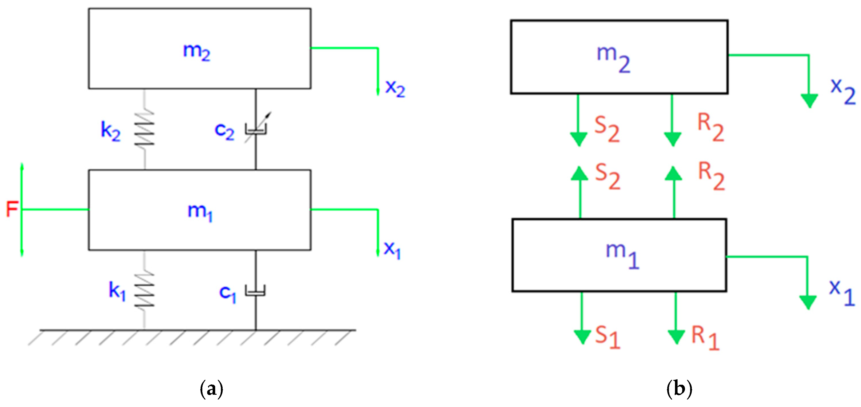
The backstepping control method is used for ¼ of a car model. It is a classic system with two degrees of freedom and enforcement. The diagram illustrating forces acting on individual elements is shown in
Figure 1.
The following motion equations are derived from
Figure 1a,b:
where:
With the substitution of Equations (2)–(5) to the system of Equation (1), the following equilibrium equations are obtained (6):
where:
= 90 (kg)—unsprung mass;
= 500 (kg)—mass of ¼ of a car;
= 200 (kN/m)—tire stiffness;
= 40 (Ns/m)—damping coefficient;
(N/m)—suspension spring stiffness described with characteristics in
Figure 2;
(Ns/m)—damping coefficient of the damper. It assumes values from 1100 to 2500 (Ns/m) during work.
where:
—deflection of car suspension.
Deflection x is the difference in positions of the body and the wheel. In the case in question, it is important since the spring is described with a different equation when the displacement is higher than 0.1 (m), which is shown in
Figure 2.
Figure 2 displays the nonlinear characteristic of the elastic element of the suspension. It can be seen that the increase in forces in the spring is related to the static position of the body in relation to the wheel of the vehicle. Then, with the same deflection of the suspension, different spring forces can be obtained, which is related to the static deflection. Therefore, the suspension deflection value was adopted for the tests. The advantage of such a solution is a constant value of force and independence of enforcement from constant parameters, such as vehicle weight.
3. Backstepping
In order to start determining the backstepping, first, it needs to be assumed that the parameter used to control the system is
[
19,
20,
21] so that we can write:
where:
—control input.
It was assumed that the first subsystem is the position of the body on an axis perpendicular to the driving direction. Next, the derivative was calculated, which can be described with simple Equations (9) and (10), and virtual control was introduced to the subsystem
designated as
:
where:
—the virtual control of the subsystem.
Then, based on the materials [
12,
22,
23], the Lyapunov function was determined (11), and the derivative (12) was calculated:
where:
—the Lyapunov function for the first subsystem
The next step is to substitute the Lyapunov function in the derivative
:
If the system has a solution that belongs to the set of real numbers, it needs to satisfy the specific conditions:
based on [
14,
17,
24,
25].
When the above conditions are met, the subsystem
can be seen as stabilized. The derivative of the subsystem
was calculated, which was described with this equation:
by, the first corrective constant
was introduced
where:
—the first corrective constant.
Then, the derivative
was calculated:
The next step is to substitute all equations to subsystem
:
By assuming that
, it was checked for which values
. This corresponds to the condition:
In order to stabilize the second subsystem, the Lyapunov function for both equations should be determined, and the function derivative needs to be calculated [
26]:
where:
—the Lyapunov function for both subsystems.
By introducing the second corrective parameter
, we should consider [
6]:
where:
—the second corrective parameter.
The second to last step is to check for which values of the corrective constant
. The following equation is greater than 0 based on [
26]:
The final step is to determine the control parameter from Equation (25). Corrective constants and were determined empirically based on Matlab simulations where the setpoints changed by 1. Ultimately, the best effects were achieved for setpoints of 999 and 1, respectively. The worst results were achieved for and of 100 and 1. The best results were achieved for and equal to 1 and 999. Moreover, a trend indicating improved stabilization time was determined when increased and dropped.
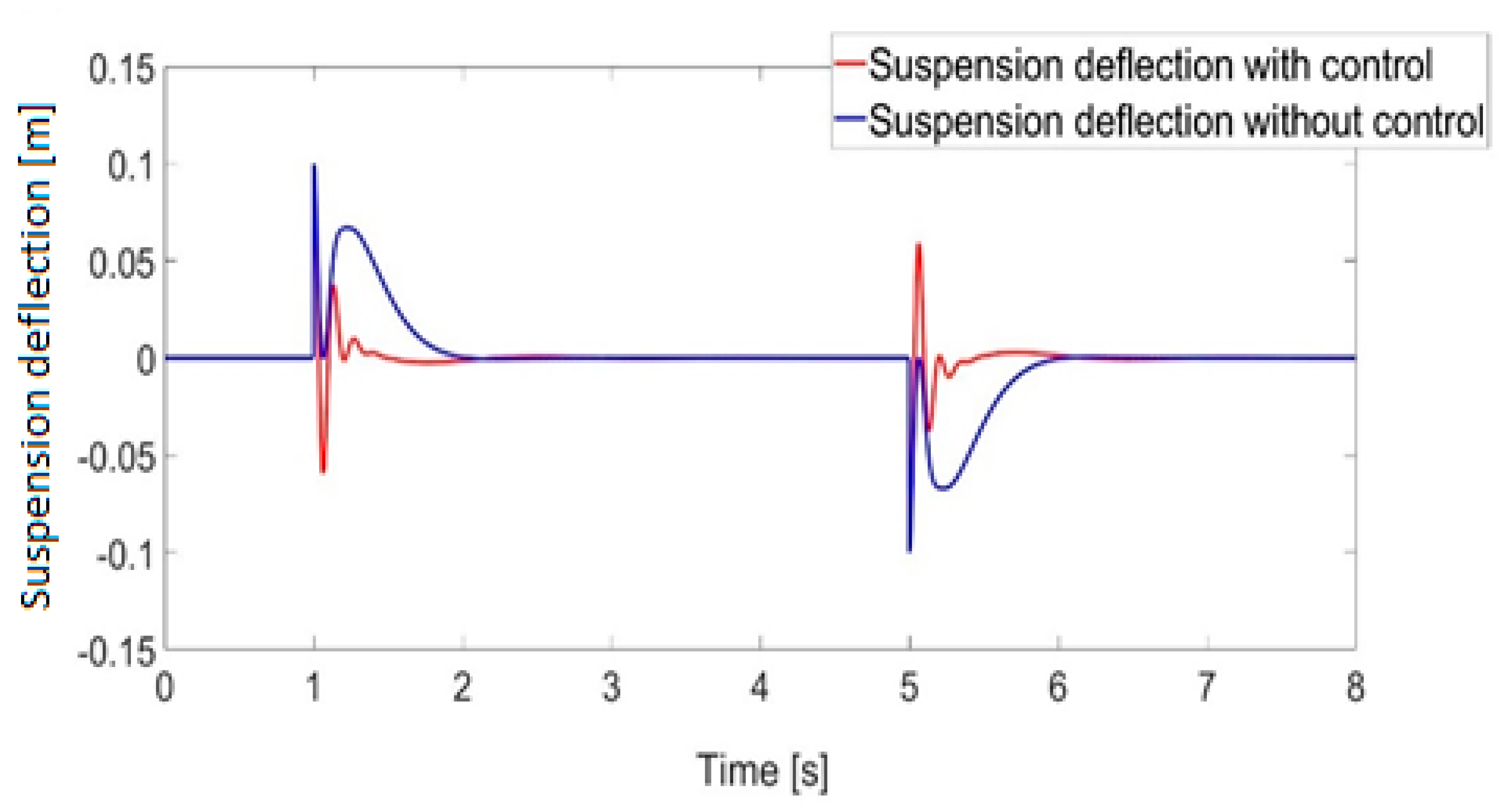
Figure 3 presents the comparison between the suspension deflection with control and without. The stabilization time for suspension with control is about 0.4 (s) shorter than in the case of suspension without control. Moreover, the trend of the amplitude of the control system is significantly greater in the pursuit of equilibrium position than in the system without control. The damping coefficient for a system without control is 4 (kN/m); this value for a linear system could be too large, but it should be remembered that it is a nonlinear system, and during the force of 0.1 (m), the stiffness parameter value
dynamically changes from 12 (kN/m) to 18 (kN/m) [
13].
4. Numerical Experiment of Backstepping Control
The system was modeled in a Matlab-Simulink environment where the control parameter is the damping coefficient of the damper marked as
, in which the magnetorheological fluid is present. By using the technical documentation made available by LORD [
27], the range in which the damping coefficient [
28] varies was limited to 1100 and 2500 (Ns/m). These values were determined based on the dependence of damping force for the maximum and minimum current acting on the magnetorheological fluid. Additionally, nonlinearity was introduced to the system by using a spring in the suspension with varying characteristics (
Figure 4). With the forced displacement, the system was thrown out of equilibrium, which, under physical conditions, means that the wheel encountered an obstacle. The goal is to determine the impact of individual damage on vibration damping and control. The following simplifications were introduced to the modeled system:
Figure 4.
MR damper characteristics and theoretical model.
Figure 4.
MR damper characteristics and theoretical model.
In order to model the damper as accurately as possible, the signal delay was introduced based on the information in [
29] of the change in the damping parameter of 0.06 s. Therefore, the first enforcement peak impacts the suspension with minimum damping. This causes the minimization of vertical accelerations. In the next phase, which follows the enforcement of displacement, the damping coefficient in the damper increases, causing the minimization of displacement of the body and, to a lesser extent, of the wheel and stabilization time of these components. Three types of damage were modeled: damage by leakage of magnetorheological fluid; linear damage to the damper, such as damage to the coil or a bunch of conduits; and step damage to the damper, such as delamination of magnetorheological fluid.
In order to reduce the impact of damage made to the damper [
1,
30], it was put into emergency mode, which meant a change was made to the damping of the system to the level corresponding to the current 0.5 (A). This solution enables further adjustment of damping, maintaining the current adjustment range; additionally, the highest damping increase related to the current variation was used. Step damage is the damage of fixed value, and in the case of this model, it is 1000 (Nm/s) but no less than 200 (Nm/s) due to the limited damping of the magnetorheological fluid.
Linear damage is described by the function:
where:
—time.
Equation (27) should be understood as a linear change in the value of the damping parameter
. In this way, it is possible to simulate many faults of a growing nature, such as a change in the properties of the magnetorheological fluid in the form of delamination of the mixture or a fault in the electric system in the form of a change in the current applied to the coil. This type of damage models the stratification of the magnetorheological fluid or damage to the control system. Leakage of the magnetorheological fluid is the worst analyzed case of damage since it prevents damping control of the damper [
31] and reduces its value to about 40 (Nm/s). Damage of this type can be divided into two cases. The first one is when the piston rod moves only within the area of the magnetorheological fluid that remained in the cylinder, and this case is analyzed here. The function that describes the leakage is as follows:
where:
—the maximum value of displacement of unsprung mass;
—the maximum value of displacement of the body;
—basic displacement of the piston; a value of 0.1 (m) was used in the investigation.
The Equation (28) is aimed at linking the mathematical displacement of the piston of the magnetorheological damper together with the leakage and the intensity of the piston moving in the form of velocity.
The characteristics of the magnetorheological damper are usually presented in the form of the Bouc–Wen or Gamota–Filisko rheological model [
3,
5]. Modeling the characteristics of the controlled damper is very complicated. For example, Ref. [
32] presents the modeling of damper characteristics using a phenomenological description. Ref. [
1] presents research related to the identification of the parameters of the MR damper model. The damper model was used for further simulation studies.
Figure 4 shows an example of the characteristics of the MR damper in the force-velocity plane. Based on the presented characteristics, a simplified characteristic was determined, which was used for numerical research. It shows the change in damping forces related to dry friction in the damper and viscous friction. Regularization has been introduced in the model, from which it is possible to determine the damping forces depending on speed changes in the low-speed range (close to zero). In the absence of regularization, there would be a problem with the unambiguous determination of the force values at zero velocity. The adopted characteristics are often used in materials presenting the range of changes in damping forces in LORD materials [
27]. Based on the control algorithm, the damping force is determined. Then, based on the damping forces at a given velocity of damper deformation, the controlled damping coefficient
can be determined. The characteristics of variation in the controlled damping value
in the real system and in the model is shown in
Figure 5. The theoretical model of the magnetorheological damper is described by the following system of equations:
where
is the speed of damping factor change in the magnetorheological damper. The measurement data were taken from the magnetorheological damper of the LORD company.
All functions responsible for errors are placed in the model as separate submodels that, depending on the fault, modify the signal value or change the parameters of the magnetorheological damper model.
5. Simulation Results
As a simulation of the operation of the suspension system, the wheel displacement in the first second of 0.1 (m) with positive sense was assumed. In the fifth second, another displacement occurred with the opposite sense but the same value. This adjustment is to minimize the deviation of the body from the equilibrium position where the control parameter is the damping of the damper with magnetorheological fluid marked as
. Further diagrams show the results of simulations of displacements and accelerations for the body and results of simulation for systems with damages to the magnetorheological fluid as well as systems with damages to the magnetorheological fluid under the emergency mode, as shown in
Figure 5,
Figure 6,
Figure 7,
Figure 8,
Figure 9,
Figure 10 and
Figure 11. Diagrams show three types of damage: damage caused by leakage of the magnetorheological fluid in the fifth second, linear damage of the damper since the first second, and step damage of the damper from the fifth second.
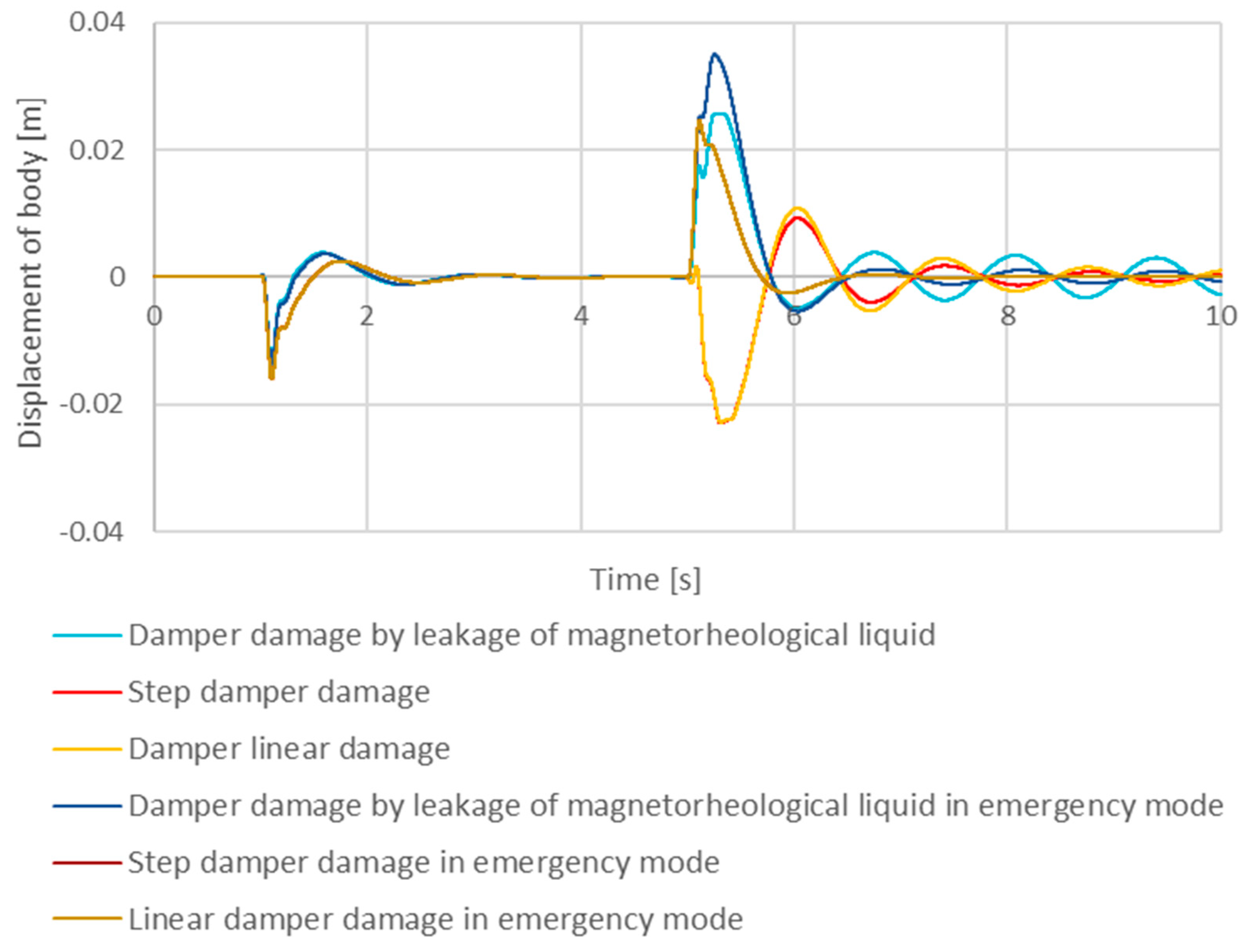
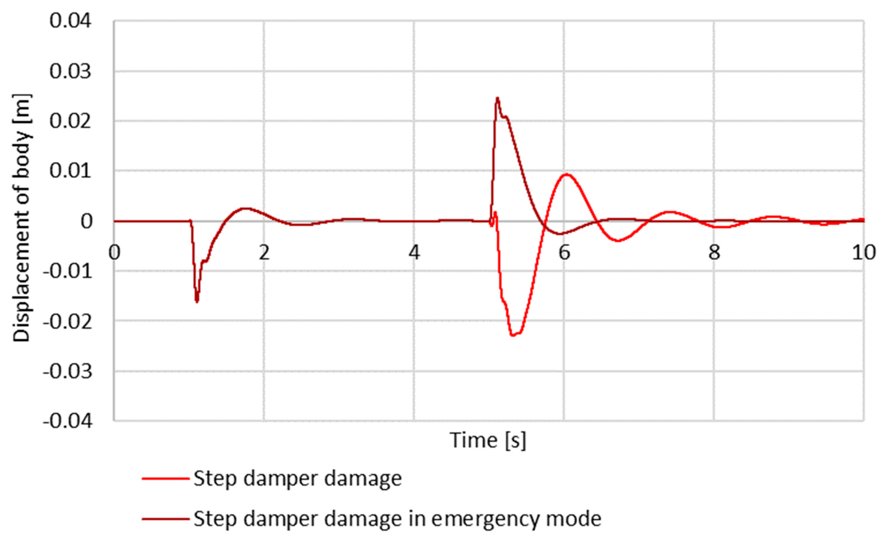
As shown in
Figure 6 and
Figure 7, the linear damage of the damper affects the body inclination amplitude from the balance position. With the increase in the damage, the system is not able to stabilize itself quickly (see also
Table 1); furthermore, all damper damage results in a longer stabilization time. Re-stabilization of the body can be observed for two types of damage after the damper is put into emergency mode.
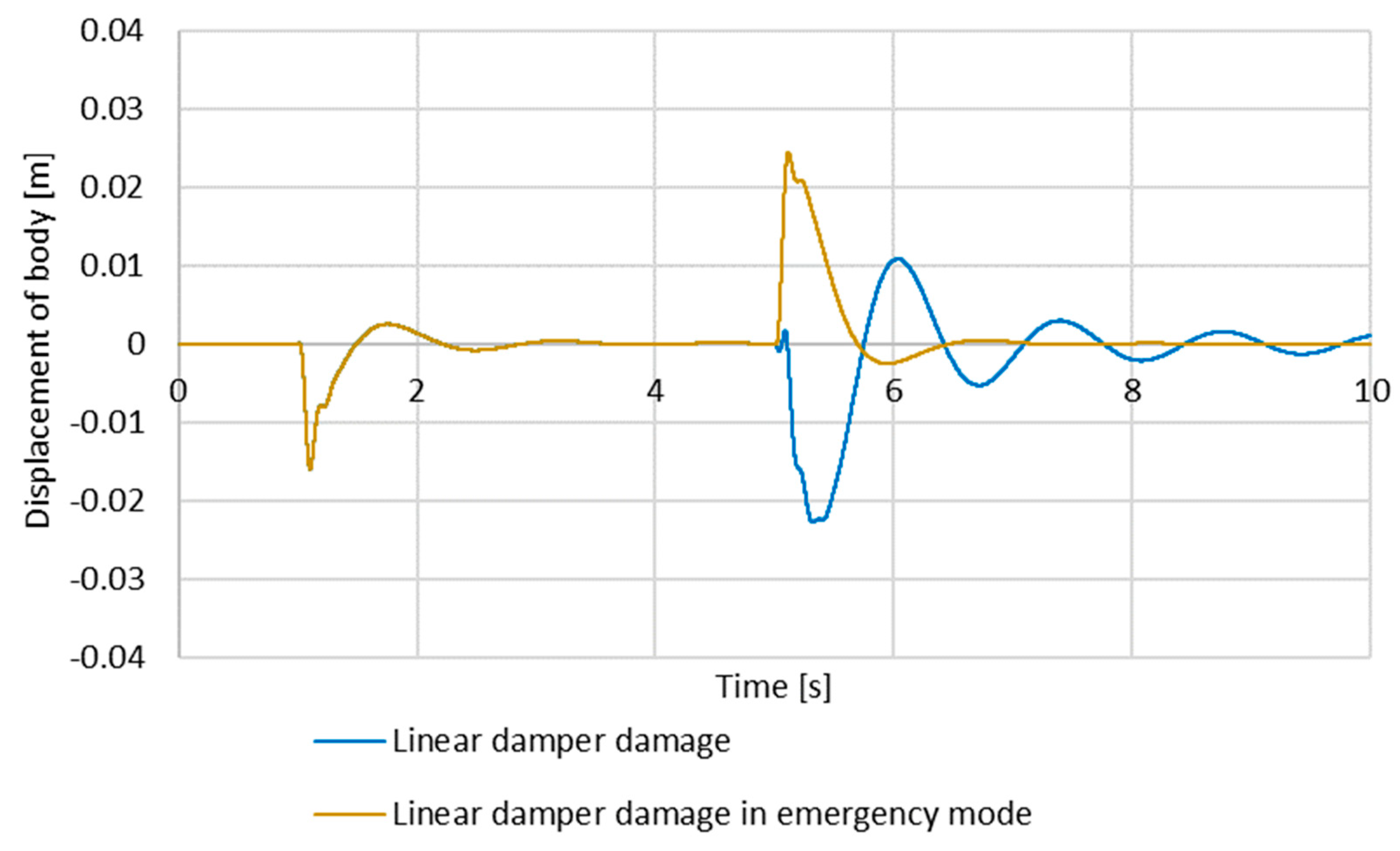
Within the time interval of 0–5 s, the system operates correctly and has no damage except the linear one. The first damage comes after the fifth second, and this is when the damper is affected. The linear and step damage of the damper changes the body displacement phase, which is caused by the varying damping parameter. It can also be seen that in the case of simulation with linear damage of the damper, it can be observed that the system falls into oscillations, which is also of concern and affects the driving comfort significantly and is destructive for the vehicle itself.
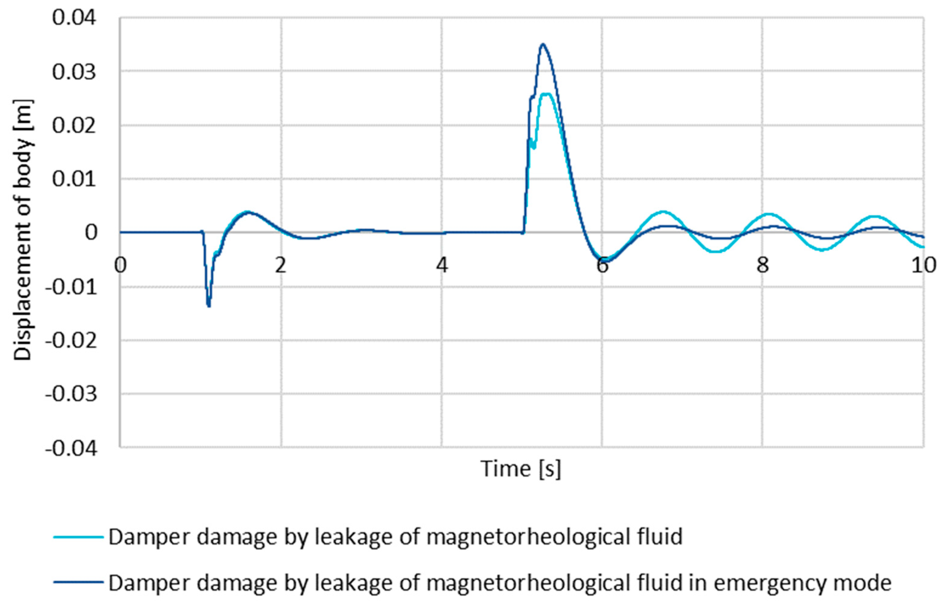
The leakage of magnetorheological fluid is the worst case of damage due to the limited damping within wide ranges of displacement. With the increased duration of the damage, the range in which the system has the proper minimum damping is smaller, and further adjustment is possible. Because of this, the activated emergency mode initially increases the enforcement amplitude for the body, but for small amplitudes, such a system will stabilize faster. The minimization of the damper displacements causes the work within the magnetorheological fluid, making it possible to dampen the displacements. Body displacements for the damper with leakage and for the damper with a leakage in the emergency mode are virtually the same. Including the safety mode, the body displacement amplitude was increased, which is the effect of greater damping as the base value. Instead, a smaller range of amplitudes was obtained.
Putting the damper into an emergency mode under step damage increased the body displacement amplitude because the vehicle with this configuration is fitted with a hard suspension, and from this solution, the system re-stabilizes within the time, similar to a working system [
33].
Liner damage extends the stabilization time and the body displacement amplitude, which affects driving comfort. Putting the damper into emergency mode reinstates a satisfying stabilization time after about 2.5 s from triggering. Unfortunately, just as in other cases, this increases the body displacement amplitude. During the enforcement phase, the damper changes the direction of displacement, which means there are two possible solutions [
34]. The first is the suspension system breakdown, which the control system has no control over. The second one, less severe, is a situation in which the damper damaged the coil, which may also mean the bending of the rod of the MR damper.
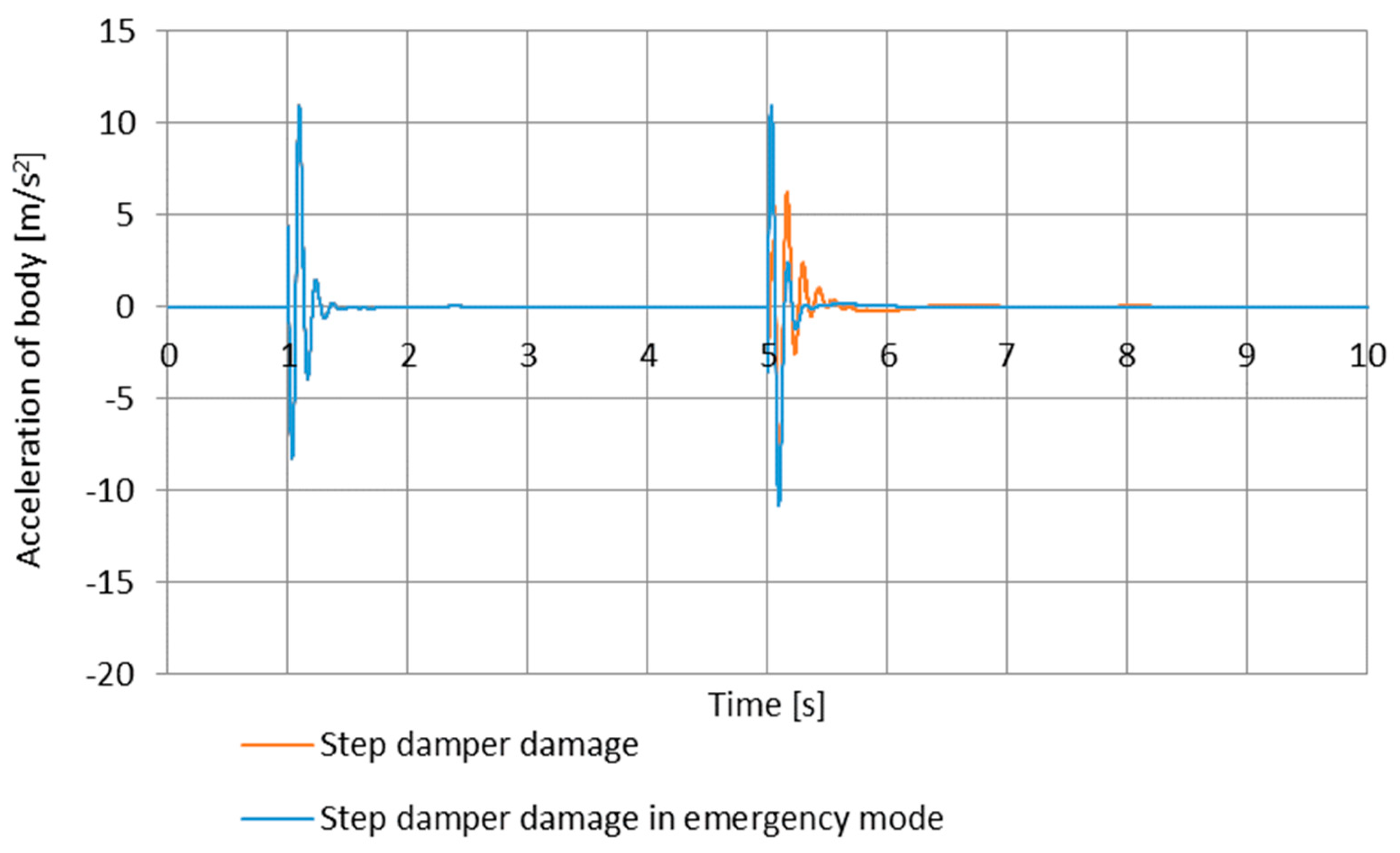
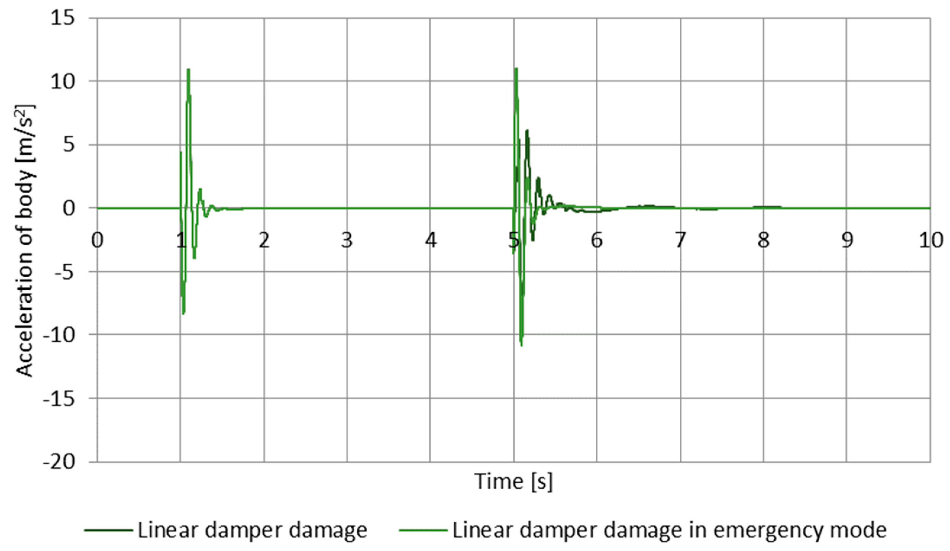
The body accelerations under emergency mode increase, which causes greater discomfort for the passengers, and in exchange, the accelerations are minimized in respect of time, and the amplitude of displacements in further periods after enforcement is smaller.
It was determined that the stabilization time corresponds to the decreased displacement amplitude below 2% of the displacement caused by enforcement. Simulations where the damper with magnetorheological fluid was damaged showed that this damage considerably extends the stabilization time of the body. The system parameters after putting the damper into the emergency mode deteriorated considerably; however, the stabilization of the suspension system was achieved, which improved the vehicle’s safety against the system and affected the damage.
Let us note that putting the damper into emergency mode resulted in improved parameters for all analyzed cases. During the enforcement, the displacement amplitude and body acceleration amplitude increased, which is caused by a higher hardness of the suspension and has a negative effect on driving comfort. In exchange, the efficiency of the suspension system was regained. Body vertical accelerations after turning into emergency mode are minimum and just after 5.25 s, while for the damper damage system, after 5.50 s, the passengers can feel the overload. Moreover, the amount of tilt from the equilibrium position is greater, which increases the negative impact on ride comfort. The assumed values of specific coefficients are as close as possible to the actual parameters of elements used. It was discovered that the use of the spring with nonlinear characteristics coupled with a controlled damper is a good alternative for conventional suspensions. In the damage associated with leakage of the magnetorheological fluid, continuing the journey is dangerous, especially traveling at higher speeds where a very soft suspension can cause a much larger lateral tilting of the body, which can lead to the loss of grip and accidents [
35]. Moreover, traveling at low speeds causes the damper to behave with a tendency to wave, which can cause a reduction in passenger comfort and, in extreme cases, motion sickness. Further research in this field will allow for the introduction of such a solution in a car and improve the safety of the vehicle with this type of suspension in case of damage to the suspension system. Tests of damage to the magnetorheological damper concluded successfully, where the emergency mode allowed in two of three cases to regain the efficiency of the suspension system.


