Article

A Comparison Study of Hydro-Compact Generators with Horizontal Spiral Turbines (HSTs) and a Three-Blade Turbine Used in Irrigation Canals

by
Wiroon Monatrakul
1,
Kritsadang Senawong
2,3,
Piyawat Sritram
4 and
Ratchaphon Suntivarakorn
1,*
1
Department of Mechanical Engineering, Faculty of Engineering, Khon Kaen University, Khon Kaen 40002, Thailand
2
General Education Teaching Institute, Khon Kaen University, Khon Kaen 40002, Thailand
3
Postharvest Technology Innovation Center, Science, Research and Innovation Promotion and Utilization Division, Office of the Ministry of Higher Education, Science, Research and Innovation, Bangkok 10400, Thailand
4
Faculty of Agriculture and Technology, Rajamangala University of Technology Isan Surin Campus, Surin 32000, Thailand
*
Author to whom correspondence should be addressed.
Energies 2023, 16(5), 2267; https://doi.org/10.3390/en16052267
Submission received: 24 December 2022 / Revised: 12 February 2023 / Accepted: 24 February 2023 / Published: 27 February 2023
(This article belongs to the Topic Hydroelectric Power)

Abstract

:
This study aimed to present the experimental results of two types of turbines and attachments used in a hydro-compact generator. Two Horizontal Spiral Turbines (HSTs) with blade angles of eighteen and twenty-one degrees, respectively, and a three-blade turbine were tested and experimented in a laboratory at five levels of water flow rate ranging from 1–2 m/s. After the efficiency and torque values of each turbine were identified, they were installed in two 200 W power generator systems: (1) with a “diffuser” attachment; and (2) with an “in-line+diffuser+nozzle chamber” attachment, and tested in a local irrigation canal with 1.2 m/s. The results from the laboratory indicated that the HST with a twenty-one degree blade angle had 38.10% efficiency at the water flow rate of 2 m/s. It could reach 120.0 rpm and produced 212 Nm of torque. The results from the field experiment revealed that the combination of the power generator with the twenty-one degree blade angle HST and the in-line + diffuser + nozzle chamber attachment was the most efficient, with 284 Nm of torque at 108 rpm and could generate 67.63 W of electrical power. When the water flow rate of the irrigation canal reached 1.5 m/s, it could reach 114 rpm and generate 129.2 W. This hydro-compact generator set is suitable for irrigation canals with a water flow rate ranging from 1–1.5 m/s.

1. Introduction

Climate change causes incidents that challenge humankind to endure. The United Nation Office for Disaster Risk Reduction (UNDRR) states that some human activities have caused these drastic global disasters [1]. Global warming is one of the most serious problems faced by humankind, responsible for drastic weather changes caused by burning fossil fuels and population expansions. In the near future, there is expected to be a trend of power shortages that will lead to the increased usage of clean and renewable energy by every country in the world [2,3]. Clean and renewable energy usage is expected to have fewer effects on the environment than fossil fuels. However, clean and renewable energy from hydro-power plants can still harm the ecosystem, because their establishment requires immense areas of land [4,5].
In Thailand today, the capability of electrical power production from hydro-power plants throughout the country is 3107.51 megawatts (MW.), which accounts for 23.01% of Alternative Energy Consumption. Thailand aims to gather 3228 MW. from hydro-power plants by the year 2037 [6]. Although geographical limitations obstruct further establishment of large hydro-power plants, Thailand has other potential sources of hydro-kinetic power, such as local irrigation reservoirs, irrigation canals, or local administration sectors, that can provide aid for villages and communities to produce electrical power from water sources [7].
Many studies indicate that there are plenty of irrigation canals in Thailand. However, most of them have the low water flow speed rate of about 0.52–2.0 m/s [8]. Thus, extracting electrical power from these canals requires a special hydro-power generator that is designed to operate under low water flow speed (less than 2.0 m/s) or low head pressure (less than 0.3 m). For ultimate performance, the generator requires an effective small-size turbine within the system. This kind of turbine must be eco-friendly, and must be well-accepted by the majority of people [9,10,11]. However, leaves, waste, or debris in the canals must be considered because, as they flow along, they might clog up the generator’s water inlets [12,13]. Some living creatures in the water may also be trapped inside and injured [14]. Despite these concerns, this Pico power generator system can benefit houses or small villages [15,16]. The output wattage can be predicted if there is sufficient water in the system [17]. Moreover, this kind of generator has a positive environmental impact [18,19].
River Current Energy Conversion Systems (RCECS) is a system that was proven to be able to convert the kinetic energy of water flow in rivers into other forms of useful power effectively. One key factor that makes RCECS successful is the cost of power production, including operation and maintenance costs. Moreover, the design, applications, capability, and practicality of RCECS have created accountability [20]. Thus, the adaptation of RCECS in this study will strengthen the proof of the system to be a powerful and effective alternative of gathering renewable energy.
The principle of water current power indicates that most of the water volume flowing horizontally in any natural source must have direction and speed. This can be a source of electrical power harvest [21,22] when a turbine hydro-power generator is installed [23]. The electricity is generated from a transformation of water flow power into kinetic power at the axle of the generator’s turbine; still, there is a power loss in the system [24]. There are many types of water turbines in hydro-power generator systems, largely divided into two groups according to their axle configurations (vertical and horizontal). Horizontal-axle turbines are further divided into two types according to their applications; vertical and horizontal installations [25]. Turbines in whirlpool hydro-generator systems, as well as Induced Vibration (VIV) turbines [26], have also been developed. Therefore, to achieve the most practical and effective goal of extracting renewable energy from local irrigations requires choosing the right applications that suits the water flow characteristics and the size of the power generator. Betz’s law indicates that the extracted peak power coefficient value from a turbine is 59 percent. However, in reality, the extracted power values are lower because of the loss from the turbine’s characteristics. Therefore, the power loss value in the system must be included in the experiments [27]. A proper turbine type selection for this circumstance must be carefully selected for the highest potential and the lowest eco-impact, as well as for low production cost. Moreover, there are studies concerning different types of turbines used in hydro-generator systems in irrigation canals with water flow rates from 0.6–3 m/s, as shown in Table 1 [28].
A properly designed Horizontal Spiral Turbine (HST) can achieve the highest efficiency. Its key feature is the ability to reduce the turbulence generated by the impact of high-pressure water flow with the surface of the blade. This is obviously a benefit to the generator’s efficiency and performance. Another obvious unique feature is that HST can be applied to wind and water generators with low-speed flow. HST’s advantages are the low cost of production, compactness, and an ability to operate effectively under low pressure head. A hydro-generator system with an HST application can be properly used in rivers, canals, and irrigation canals without doing serious harm to living creatures in the water. It can be harmlessly blended with ecosystems; moreover, the construction materials are not expensive [36]. HSTs have been designed based on Fibonacci functions [37] and the golden ratio [38]. They are an arithmetic series of natural phenomena according to Fibonacci sequence principles. One round of rotation (360 degree) of an HST axle is equal to a length. Thus, the angle of the blades alters the length. The last characteristic of efficient HST relates to the number of blades. If the number of blades is insufficient, the surface area for converting force will cause the HST to generate low torque. On the other hand, if the number of blades is too high, the HST will create a solid wall state. Too many blades also increase the HST mass and inertia that reduce the overall torque [39]. Ratchapol et al. (2016) discovered that, under low water velocity and with between two and six blades, an HST with three blades could achieve the maximum torque and most optimal performance [40].
Yasukuni Nishi Okubo and Norio Kikuchi designed a new hydro-compact generator system that had “a runner” and “a collection device” including “a diffuser section” to enhance the water flow through the turbine. This increased power extracting ability and flow rate by 2.76% in a hydroelectric power generator with a three-blade turbine. At 456 rpm and a water flow rate of 1.72 m/s, 156.4 watts of electric power could be generated [41,42]. Hidayat et al. (2020) proved that a hydro-spiral turbine could spin faster (90 rpm) than other types at the same water volume [43]. Ratchapol et al. (2016) used the golden ratio function to enhance the efficiency of spiral turbines by extending the blade’s radius and adjusting the diameter/length (D/L) ratio to 2/3. They proved that a spiral turbine had proper efficiency when compared with the a three-blade turbine. A hydro-generator with a proper spiral turbine could effectively generate electrical power at water flow rate ranging from 0.5 to 2 m/s [40]. Wiroon and Ratchapol (2017) also proved that a horizontal spiral turbine in a hydro-generator system with a nozzle chamber inlet was more efficient than one with a free flow inlet. Moreover, the blade angle also significantly affected the system’s performance and efficiency [44]. Uday Y. Bhenede (2015) had designed and developed a turbine in a hydro-generator system that could effectively operate under low water pressure. It was a small-size turbine in a generator system that could operate under variant head pressure [45].
Today, HST research and development is focused on identifying the best values of different blade angles, length/axis radius ratio, blade number, or torque. Therefore, in this study, two Horizontal Spiral Turbines (HSTs) with blade angles of eighteen and twenty-one degrees, respectively, and a three-blade turbine, were tested in a laboratory at five levels of water flow rate ranging from 1–2 m/s. After the efficiency and torque values of each turbine were identified, they were installed in two 200 W power generator systems: (1) with a “diffuser” attachment; and (2) with an “in-line+diffuser+nozzle chamber” attachment, and tested in a local irrigation canal with a water flow rate of 1.2 m/s.

2. Materials and Methods

Laboratory experiments and related equations
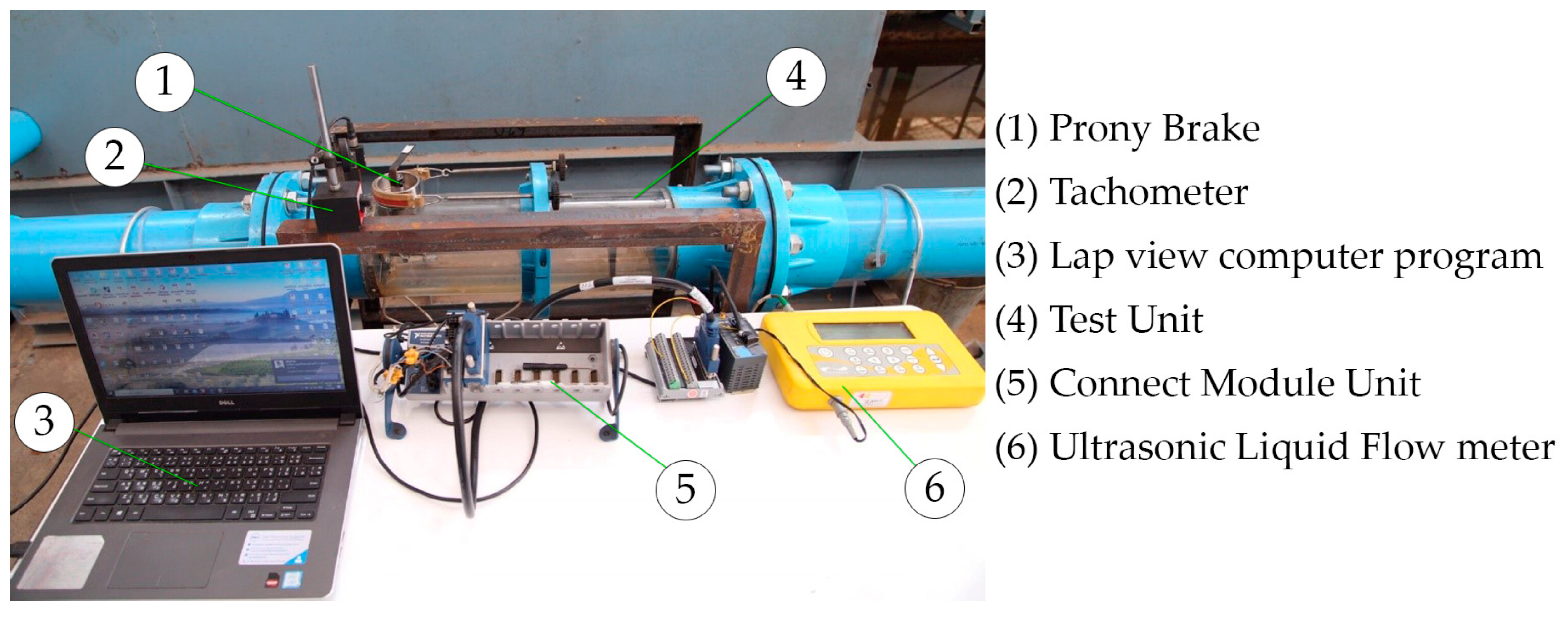
This study aimed to design 3-blade Horizontal Spiral Turbines with blade angles of 18 and 21 degrees used in a hydro-generator system [40]. The simulation was set as displayed in Figure 1 and Figure 2 and was simulated in a laboratory. The generator was fitted with 6 inches of spiral turbine. It was attached with 6 inches of PVC pipes and its body was a clear acrylic for better performance observations. The simulator system could generate 5 levels of water flow speed ranging from 1–2 m/s, which represented the actual current in local irrigation canals with a flow speed rate of 0.5–2.0 m/s throughout the region [8]. The initial torque power and torque power was identified using Equation (1) [46,47,48]. Later, in the field experiments, the turbine size was increased to 15 inches.
P t , o u t =   2 π τ N 60
P t , o u t   =   Power   Output   ( kW )
τ   =   Torque   ( Nm )
N   =   Revolutions   per   minute   ( RPM )
Value measurements in the laboratory were operated by using: (1) an Ultrasonic Liquid Flow Meter; Micronics Portaflow PF300 for water flow rate (m/s), (2) a Tachometer Light Sensor Module for RPM, and (3) a Local Cell Module for torque at turbine axles. These values were processed by Lab View NATIONAL INSTRUMENTS NI cDAQ-9178 to identify the generated power and turbine efficiency. This laboratory simulation was carried out according to Gianluca Zitti et al. (2002) [49]. Torque values from each turbine model were studied and evaluated for appropriate uses in real contexts.
Power and efficiency of turbines at different water volumes and flow speeds were identified using Equations (2) and (3). The peak power of turbines was identified using Equation (4) [50,51].
P t , i n = ρ g Q H n
η = P t , i n P t , o u t
P t , o u t = [ 16 27 ] [ 1 2 ] ρ A v 3
P t , i n   =   Power   input   ( kW )
ρ   =   Water   Density   ( kg / m 3 )
g   =   Gravitational   of   mass   ( m / s 2 )
Q   =   Water   Volume   ( m 3 / s )
H n   =   Head   Pressure   ( m )
η =   Efficiency
16 27   =   Max   Power   Coefficient   ( CPmax )
A   =   Turbine   Surface   ( m 2 )
v   =   Water   Flow   Speed   ( m / s )
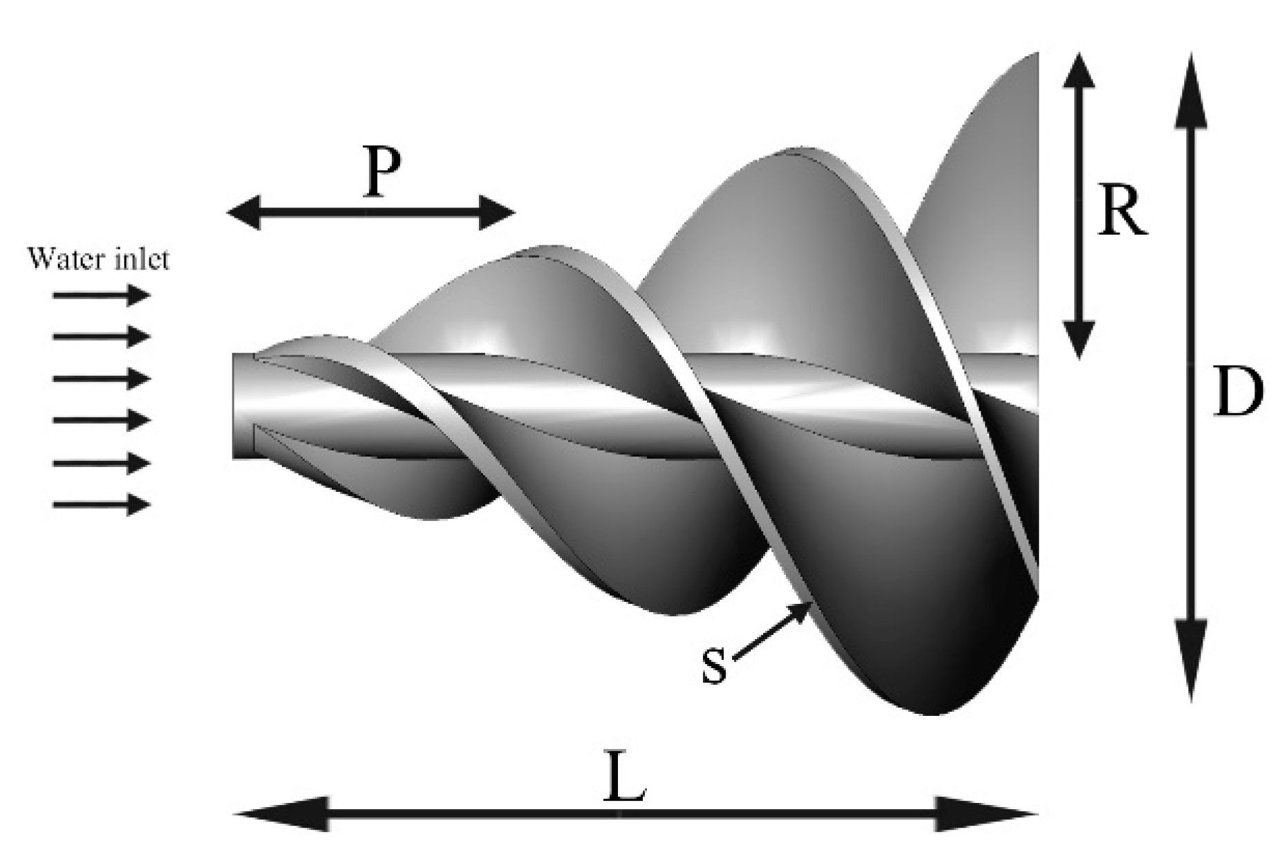
One rotation of the HST axle (360 degree) determined the width and the length of the turbine. The fixed pitch (L) and fixed diameter (D) are displayed in Table 2. HSTs with 18 and 21 degree blade angles, and the three-blade turbine, are displayed in Figure 3 and Figure 4.
“L” represents the height at one round of rotation. “s” represents the peripheral length of the HST. “R” represents the HST radius. “N” represents the number of rounds of rotation. All the variables were used in Equations (5) and (6) for the design.
r ( t ) = 2 π N R L sin ( 2 π N t L ) i + 2 π N R L cos ( 2 π N t L ) j + k
s = 4 π 2 N 2 R 2 + L 2
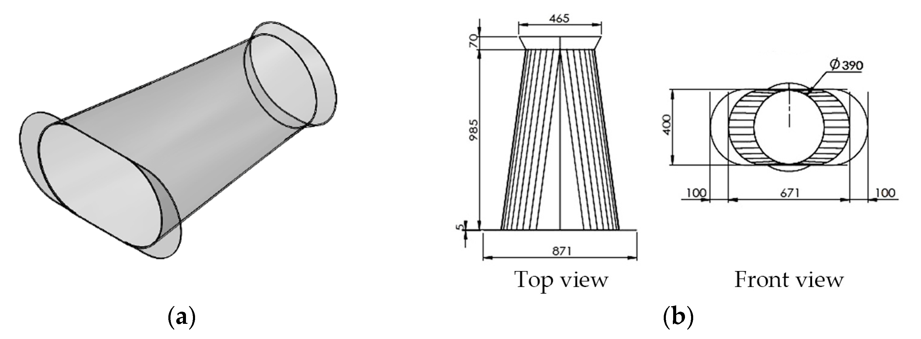
The collective chamber (see Figure 5) was designed according to Yasuyuki [41] to regulate the inlet fluid pressure of the system [52]. It was also attached with a rudder to enhance the water flow rate.
Power Output ( η )
The power output was identified using Equations (7) and (8) [53].
η = P e P m
P e = EI
E = Voltage (V)
I = Current (A)
P e   =   Power   Output   ( W )
P m   =   Power   Output   from   Water   Power   ( W )

3. The Field Experiment

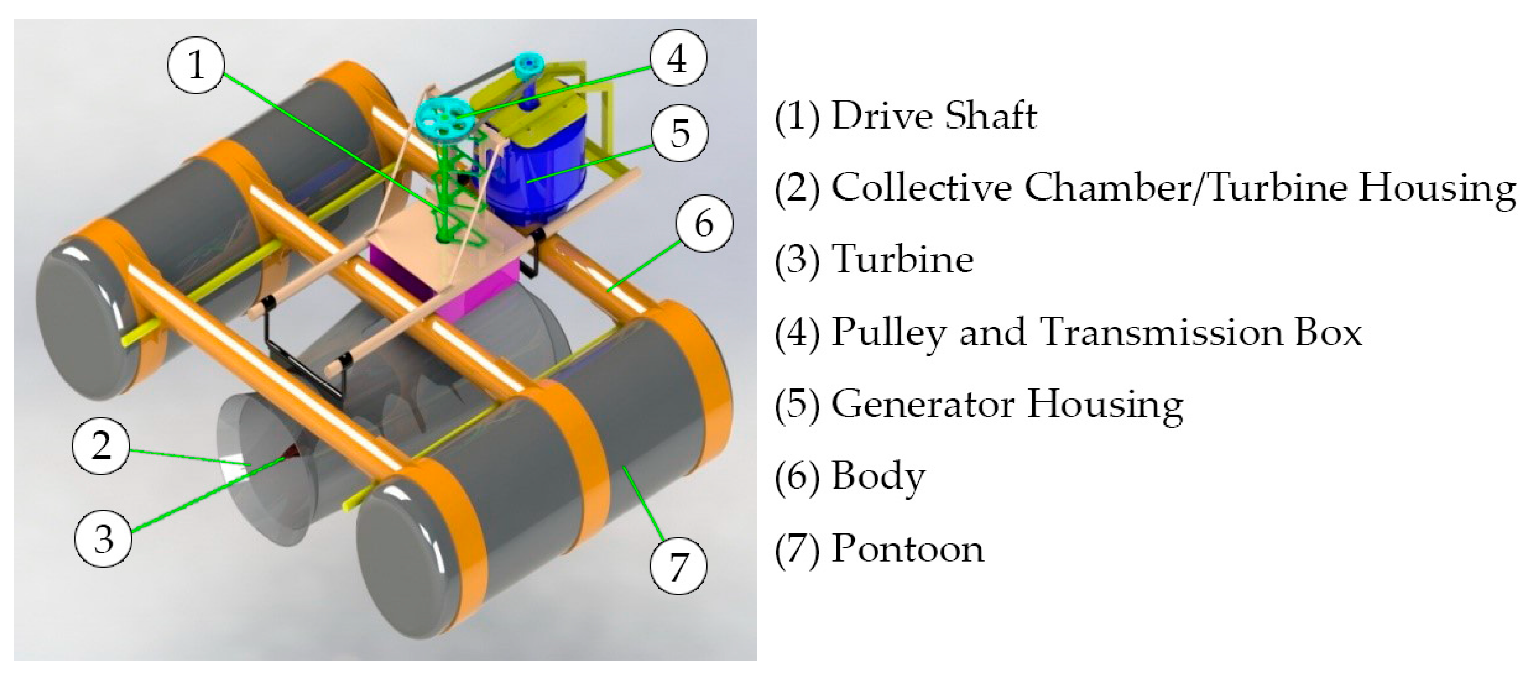
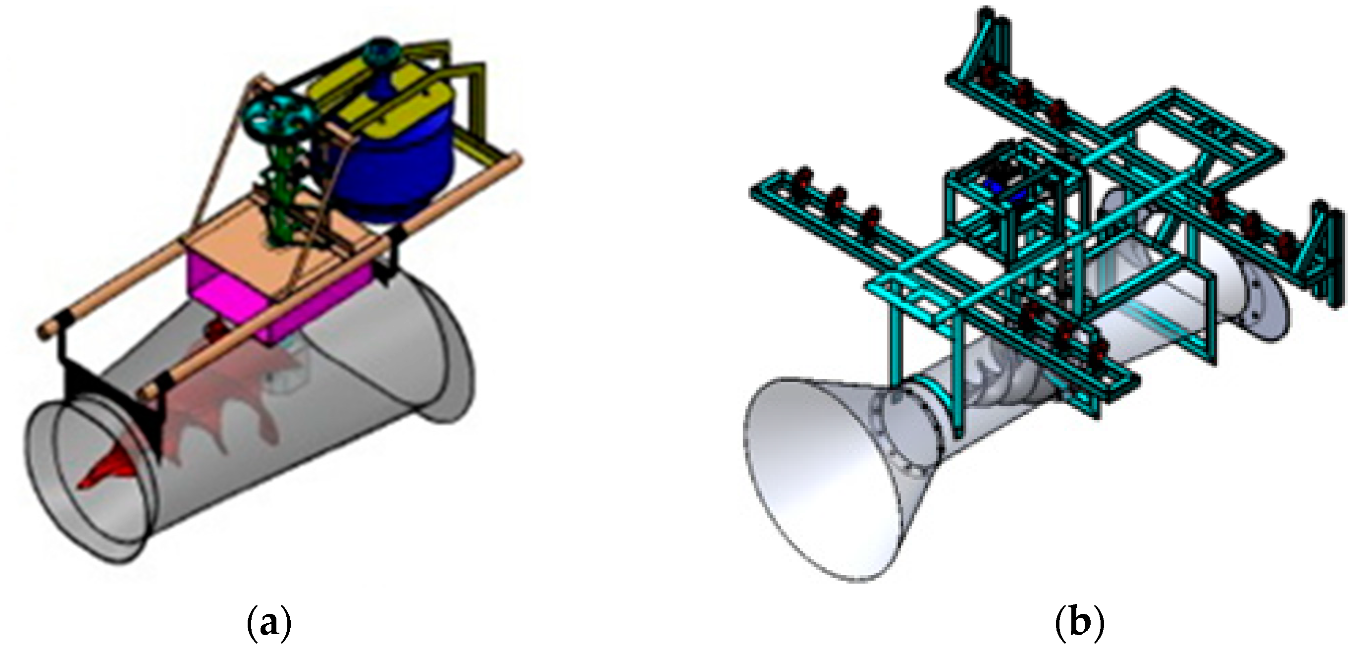
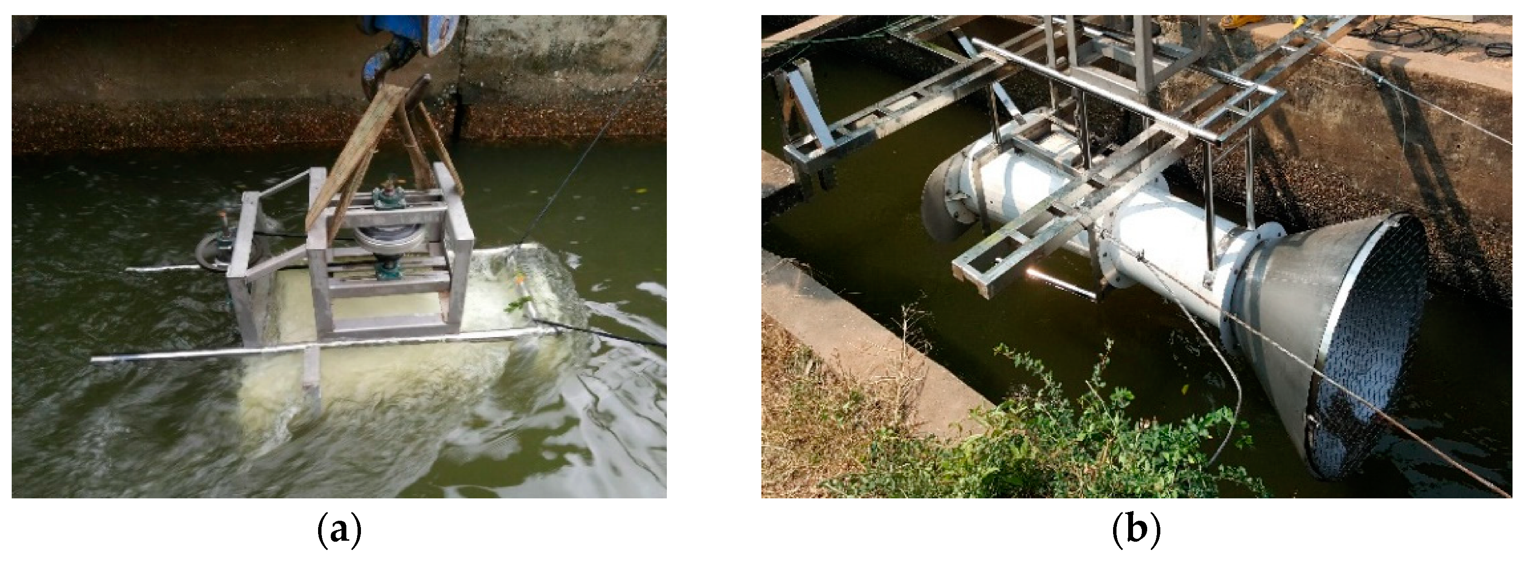
A diffuser was attached to the turbine housing of a 200 W electrical power generator (Table 3) as displayed in Figure 6. A 15-inch-diameter HST with an 18-degree blade angle, a 15-inch-diameter HST with a 21-degree blade angle, and a three-blade turbine 15 inches in diameter were tested in this generator system. There were two generator systems used in the experiment: (1) a generator system with a diffuser as a trumpet-shaped collective chamber attachment (see Figure 7a), and (2) a generator system with an in-line pipe + diffuser + nozzle chamber attachment (see Figure 7b). They were tested in an irrigation canal in Baan Kota, Tambol Sila, Amphoe Muang, Khon Kaen Province (see Figure 8) with water velocity ranging from 0.8 to 1.2 m/s and a water volume of 2.10–3.15 m3/s. They were planted using a rigid structure as a scaffold to set them in the middle and along the canal. The data of (1) water velocity, (2) the turbines’ RPM, (3) the turbines’ torque, and (4) the power output were analyzed using measuring devices, and this data reading process was carried out exactly as in the laboratory.

4. Results and Discussions

Turbines’ efficiency and torque from laboratory simulator
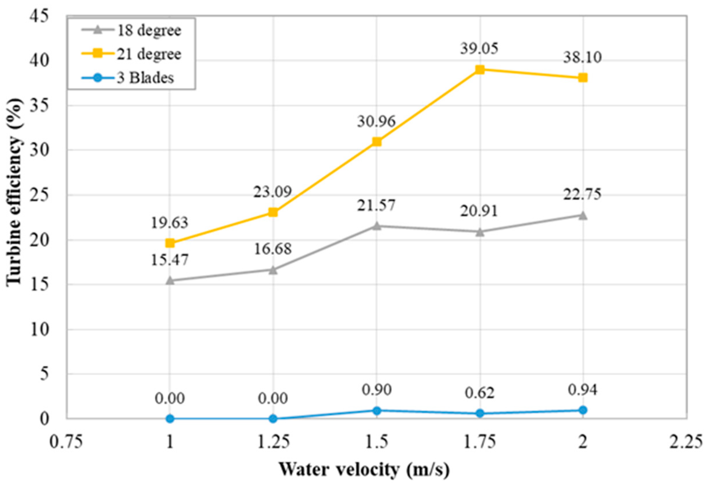
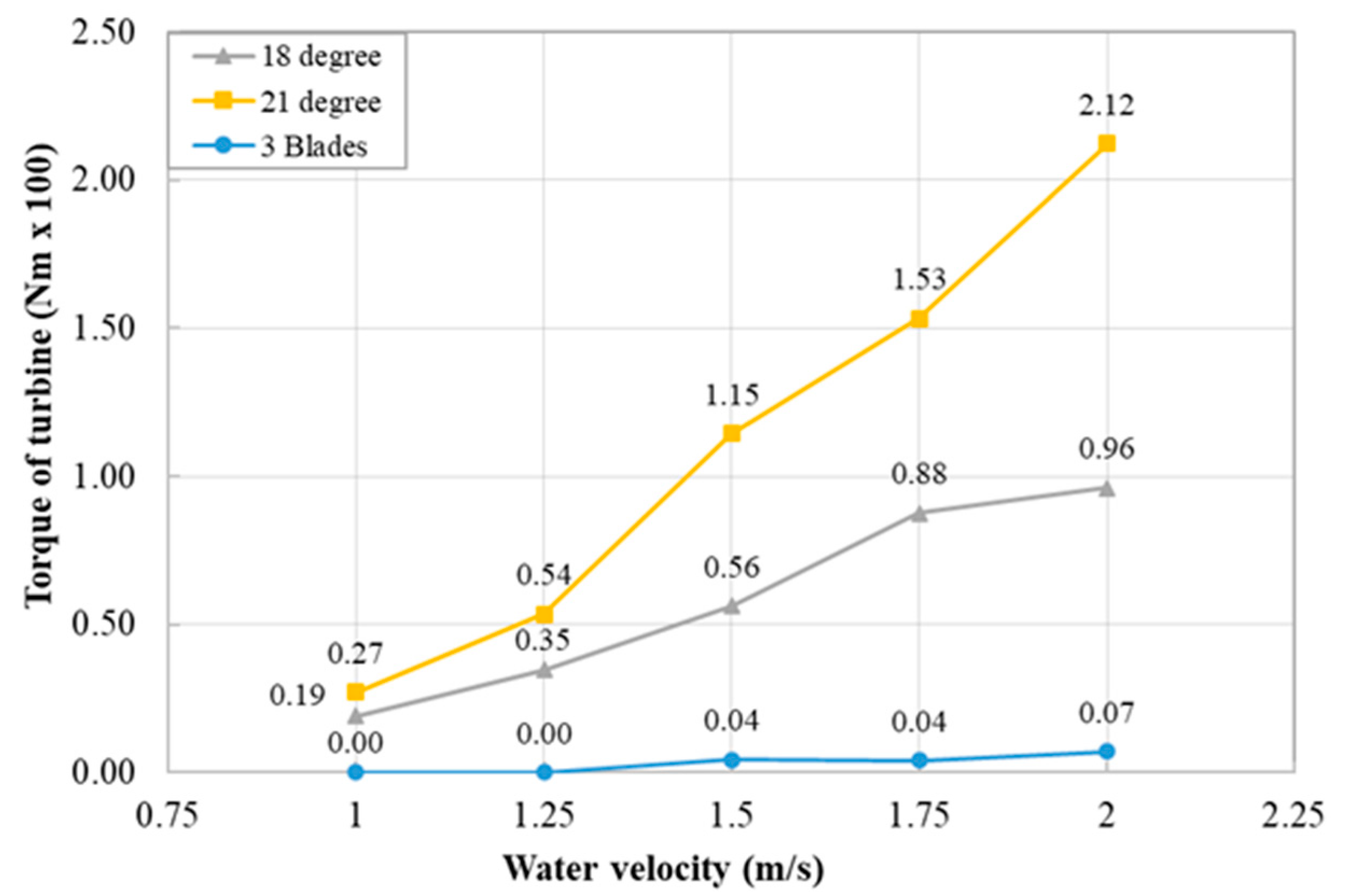
The comparison results of efficiency of the three turbine types with 6-inch diameters at different water velocities from the laboratory simulation are displayed in Figure 9. As shown below, the HST with the 21-degree blade angle reached the highest efficiency at all water flow speeds. The HST with the 18-degree blade angle’s efficiency was lower than that of the 21-degree HST. However, the efficiency of the three-blade turbine could not be determined under water velocities ranging from 1 to 2 m/s. It needed higher water flow speed to be practical, so it had the lowest efficiency in this experiment. The HST with the 21-degree blade angle had 38.10% efficiency at 120.00 rpm of 2 m/s water velocity. It reached 39.05% at 156.63 rpm of 1.5 m/s water velocity. The results revealed that the operations of the HST with 21-degree blade angle at 1, 1.25, 1.50, 1.75, and 2.0 m/s indicated 1100, 1300, 1630, 1850, and 2100 L/s of water, respectively. Figure 10 displays the torque values generated from the HSTs and the three-blade turbine. All torque values were altered by water flow speed. The 21-degree HST generated the most torque at 212 Nm at 2 m/s water flow speed. This created data that can be used as a reference in enhancing systems for practical field applications.
Field Experiments
The torque values of the three turbine types with 15-inch diameters are shown in Table 4. From the field experiments in an actual irrigation canal with the average water velocity of 1.2 m/s, the best turbine type was the HST with the 21-degree blade angle in a generator system with an in-line + collective chamber + inlet nozzle. It had a peak torque of 284 Nm. The HST with the 21-degree blade angle in a generator system with only the diffuser/collective chamber could only generate a torque value of 217.2 Nm.
When torque values generated from the 6-inch-diameter turbines used in the laboratory simulation and the 15-inch-diameter turbines used in the field experiments from both generator systems were compared, it was obvious that the generator system with the additional modifications of collective chamber + inlet nozzle 100 cm could generate more torque. In the laboratory simulation, at a water flow speed of 1.2 m/s, the 21-degree HST with 6-inch diameter produced about 49 Nm of torque, but when the turbine diameter was increased to 15 inches, the torque values increased to 217.2 and 284.0 Nm in both generators. Obviously, the generator with higher torque could generate more power.
Power output
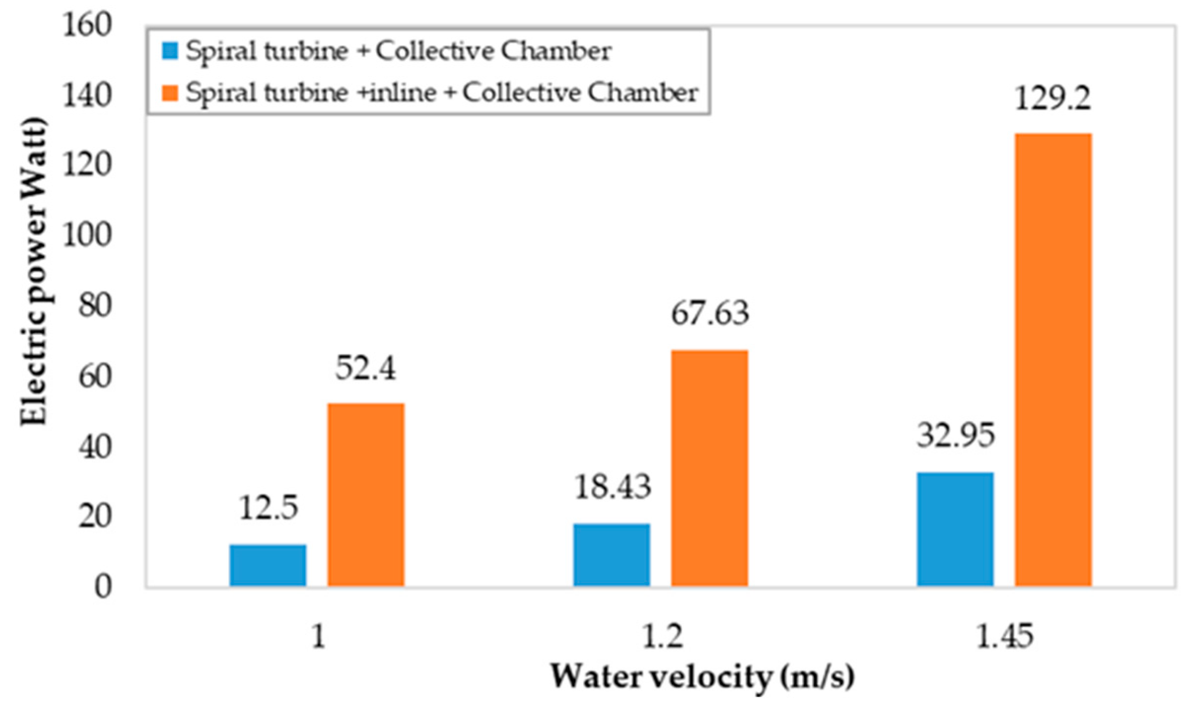
From the field experiments in an actual irrigation canal with the average water velocity of 1.2 m/s, the best turbine type among the rest that could generate the most power output (67.63 watts) was the HST with the 21-degree blade angle in a 200 W generator system with an in-line + collective chamber + inlet nozzle (as shown in Table 5). After the long-run operations at different water flow speeds, the results were as shown in Figure 11 and Figure 12. These results were analyzed and compared with related studies as displayed in Table 6.

5. Summary and Conclusions

The golden ratio function had the most important role in this study in order to verify the proper HST’s blade angles. There were three turbines (an HST with an 18-degree blade angle, an HST with a 21-degree blade angle, and a three-blade turbine) designed to be tested in two generator systems in this study. Firstly, all turbines were tested in a simulation set in the laboratory. The simulator revealed that the HST with the 21-degree blade angle had the highest efficiency (38.10%) at all water flow speeds. When the two sets of generator systems (one with a diffuser/collective chamber attachment and another one with an in-line + diffuser + nozzle chamber) were tested in an actual irrigation canal at the average natural water flow speed of 1.2 m/s, the results revealed that the HST with the 21-degree blade angle in a generator system with an in-line + diffuser + nozzle chamber could generate the highest power input of 67.63 watts. In the long-run operation experiment, when the water velocity reached 1.5 m/s, it could generate electrical power up to 129.2 watts.
The turbines used the in laboratory and field experiments were different in size because the bigger turbine size employed in the actual irrigation canal had more inertia. Thus, the transmission set attached to the generator system had to be properly designed to fulfill the turbine’s performance.
This study showed that a Horizontal Spiral Turbine (HST) in a hydro-compact generator system could effectively operate under low water flow speed. The HST blade angle could also generate high torque from low water flow speed. In conclusion, an HST in a generator system with an in-line + diffuser + nozzle chamber could significantly generate high torque and high power output in any actual irrigation canal with low water flow rate at the average of 1.5 m/s throughout the country.

6. Break-Even Point and Investments

From this study, the conditions that must be considered in order to meet the break-even point for investors are:
-
1.5 m/s average water flow speed;
-
24 h operation;
-
365 days production length;
-
0.8 (9.6 months) plant factor value;
-
USD 0.13 per one power unit selling price.
The maximum cost of production of a 200-watt hydro-compact generator with an HST and attachments is USD 2434.83 and the break-even point is 22.86 years. Details are displayed in Table 7.
In conclusion, it is obvious that the main issue of applying this kind of technology is the correlation between the cost of production and the break-even point. However, the production cost of this compact hydro-generator system is still high, whereas the low-speed water flow rate of local irrigation canals provides “not much” renewable energy. Nicolas D et al. (2016) stated that the main concerns of using HSTs were lowering the production costs, enhancing the turbines’ efficiency, environmental awareness, and public relations campaigns [58].

Author Contributions

Conceptualization, W.M. and R.S.; methodology, W.M. and R.S.; software, W.M.; validation, R.S.; formal analysis, K.S.; investigation, W.M. and R.S.; resources, P.S.; data curation, P.S.; writing—original draft preparation, W.M. and K.S.; writing—review and editing, W.M. and R.S.; visualization, W.M.; supervision, R.S.; project administration, W.M. All authors have read and agreed to the published version of the manuscript.

Funding

This research received no external funding.

Institutional Review Board Statement

Not applicable.

Informed Consent Statement

Not applicable.

Data Availability Statement

Not applicable.

Acknowledgments

The researchers are grateful to the Farm Engineering and Automation Technology Research Group (FEAT), Department of Mechanical Engineering Khon Kaen University and Rajabhat Maha Sarakham University, Agricultural Machinery and Postharvest Technology Center Khon Kaen University Khon Kaen Province 40002 Thailand, Postharvest Technology Innovation Center Science Research and Innovation Promotion and Utilization Division Office of the Ministry of Higher Education Science Research and Innovation 10400 Thailand for their support with the tools and equipment used in this research.

Conflicts of Interest

The authors declare no conflict of interest.

References

  1. UNDRR. Global Assessment Report on Disaster Risk Reduction. Available online: https://www.undrr.org/gar2022-our-world-risk (accessed on 10 December 2022).
  2. Maji, I.K. Impact of Clean Energy and Inclusive Development on CO2 Emissions in Sub-Saharan Africa. J. Clean. Prod. 2019, 240, 118186. [Google Scholar] [CrossRef]
  3. Ghimire, A.; Dahal, D.; Kayastha, A.; Chitrakar, S.; Thapa, B.S.; Neopane, H.P. Design of Francis Turbine for Micro Hydropower Applications. J. Phys. Conf. Ser. 2020, 1608, 012019. [Google Scholar] [CrossRef]
  4. Ezra, H. Unsustainable Development in the Mekong: The Price of Hydropower. Consilience 2014, 12, 63–76. [Google Scholar] [CrossRef]
  5. Northrup, J.M.; Wittemyer, G. Characterising the Impacts of Emerging Energy Development on Wildlife with an Eye towards Mitigation. Ecol. Lett. 2013, 16, 112–125. [Google Scholar] [CrossRef]
  6. Ministry of Energy. Percentage of Alternative Energy Consumption. Available online: https://www.dede.go.th/ewt_news.php?nid=48247 (accessed on 10 December 2022).
  7. Ministry of Energy. Hydro Power. Available online: https://energy.go.th/th/interested/29228 (accessed on 10 December 2022).
  8. Royal Irrigation Department. Water Situation Summary. Available online: http://hydro-3.rid.go.th/ (accessed on 23 January 2022).
  9. EGAT. Environmental Report 2015. Available online: https://www.egat.co.th/home/wp-content/uploads/2021/08/environmental_report_2558.pdf (accessed on 10 December 2022).
  10. Thailand Power Development. Thailand Power Development Plan 2015–2036 (PDP2015). Available online: https://www.eppo.go.th/images/POLICY/ENG/PDP2015_Eng.pdf (accessed on 10 December 2022).
  11. Mishra, S.; Singal, S.; Khatod, D. Costing of a Small Hydropower Projects. Int. J. Eng. Technol. 2012, 4, 239–242. [Google Scholar] [CrossRef] [Green Version]
  12. Tomomi, U.; Satoshi, H.; Tomoko, O.; Tomohiro, D. A Feasibility Study of Power Generation from Sewage Using a Hollowed Pico-Hydraulic Turbine. Engineering 2016, 2, 510–517. [Google Scholar] [CrossRef]
  13. Tomomi, U.; Satoshi, H.; Tomohiro, D. Development of a Propeller-Type Hollow Micro-Hydraulic Turbine with Excellent Performance in Passing Foreign Matter. Renew Energy 2018, 126, 545–551. [Google Scholar] [CrossRef]
  14. Čada, G.; Loar, J.; Garrison, L.; Fisher, R.; Neitzel, D. Efforts to Reduce Mortality to Hydroelectric Turbine-Passed Fish: Locating and Quantifying Damaging Shear Stresses. Env. Manag. 2006, 37, 898–906. [Google Scholar] [CrossRef]
  15. Zeleňáková, M.; Fijko, R.; Diaconu, D.C.; Remeňáková, I. Environmental Impact of Small Hydro Power Plant. A Case Study. Environments 2018, 5, 12. [Google Scholar] [CrossRef] [Green Version]
  16. Cobb, B.R.; Sharp, K.V. Impulse (Turgo and Pelton) Turbine Performance Characteristics and Their Impact on Pico-Hydro Installations. Renew Energy 2013, 50, 959–964. [Google Scholar] [CrossRef]
  17. Rakibuzzaman, M.; Suh, S.-H.; Kim, H.-H.; Ryu, Y.; Kim, K.Y. Development of a Hydropower Turbine Using Seawater from a Fish Farm. Processes 2021, 9, 266. [Google Scholar] [CrossRef]
  18. International Energy Agency. Key World Energy Statistics; OECD: Paris, France, 2017; ISBN 9789264283213. [Google Scholar]
  19. Tiago Filho, G.L.; dos Santos, I.F.S.; Barros, R.M. Cost Estimate of Small Hydroelectric Power Plants Based on the Aspect Factor. Renew. Sustain. Energy Rev. 2017, 77, 229–238. [Google Scholar] [CrossRef]
  20. Khan, M.; Iqbal, M.; Quaicoe, J. River Current Energy Conversion Systems: Progress, Prospects and Challenges. Renew. Sustain. Energy Rev. 2008, 12, 2177–2193. [Google Scholar] [CrossRef]
  21. Nyambuu, U.; Semmler, W. Climate Change and the Transition to a Low Carbon Economy-Carbon Targets and the Carbon Budget. Econ. Model. 2020, 84, 367–376. [Google Scholar] [CrossRef]
  22. Lago, L.I.; Ponta, F.L.; Chen, L. Advance and Trends in Hydrokinetic Turbine System. Energy Sustain. Dev. 2010, 14, 287–296. [Google Scholar] [CrossRef]
  23. Wanchat, S. Design and Development of Water Free Vortex Hydro Power Plant; Khon Kaen University: Khon Kaen, Thailand, 2014. [Google Scholar]
  24. Lu, Q.; Li, Q.; Kim, Y.K. A Study on Design and Aerodynamic Characteristics of a Spiral-Type Wind Turbine Blade. J. KSV 2012, 10, 27–33. [Google Scholar] [CrossRef]
  25. Yuce, M.I.; Muratoglu, A. Hydrokinetic Energy Conversion Systems: A Technology Status Review. Renew. Sustain. Energy Rev. 2015, 43, 72–82. [Google Scholar] [CrossRef]
  26. Fernandes, A.C.; Rostami, A.B. Hydrokinetic Energy Harvesting by an Innovative Vertical Axis Current Turbine. Renew Energy 2015, 81, 694–706. [Google Scholar] [CrossRef]
  27. Ragheb, M.; Ragheb, A.M. Wind Turbines Theory—The Betz Equation and Optimal Rotor Tip Speed Ratio. In Fundamental and Advanced Topics in Wind Power; Carriveau, R., Ed.; InTech: Rijeka, Croatia, 2011; ISBN 978-953-307-508-2. [Google Scholar]
  28. Vermaak, H.J.; Kusakana, K.; Koko, S.P. Status of Micro-Hydrokinetic River Technology in Rural Applications: A Review of Literature. Renew. Sustain. Energy Rev. 2014, 29, 625–633. [Google Scholar] [CrossRef]
  29. Johnson, J.B.; Pride, D.J. River, Tidal, and Ocean Current Hydrokinetic Energy Technologies: Status and Future Opportunities in Alaska. Available online: http://www.uaf.edu/files/acep/2010_11_1_State_of_the_Art_Hydrokinetic_Final.pdf (accessed on 11 December 2022).
  30. Water current turbines pump drinking water. Caddet Renewable Energy. Available online: http://www.caddet-re.org/assets/no83.pdf (accessed on 11 December 2022).
  31. Verdant Power. Technology Evaluation of Existing and Emerging Technologies—Water Current Turbines for River Applications. Available online: http://oreg.ca/web_documents/verdant_river_turbines_report.pdf (accessed on 12 December 2022).
  32. Tidal Energy Pty Ltd. The Davidson-Hill Advantage. Available online: http://tidalenergy.net.au/ (accessed on 12 December 2022).
  33. Seabell International Co., Ltd. Stream—Hydrokinetic Power Generation Systems. Available online: http://www.seabell-i.com/e/img/guide_pdf.pdf (accessed on 12 December 2022).
  34. New Energy Corporation Inc. Encurrent Hydropower Turbines 5 k Wand 10 kW Specifications. Available online: http://www.newenergycorp.ca/Portals/0/documents/datasheets/ENC.005.010.DataSheet.pdf (accessed on 13 December 2022).
  35. Eclectic Energy Ltd. Duogen-3: Combined Water and Wind Generator. Available online: http://www.duogen.co.uk/page14.html (accessed on 13 December 2022).
  36. Safdari, A.; Kim, K.C. Aerodynamic and Structural Evaluation of Horizontal Archimedes Spiral Wind Turbine. J. Clean Energy Technol. 2015, 3, 15–20. [Google Scholar] [CrossRef] [Green Version]
  37. Spira, M. On the Golden Ratio. In Proceedings of the ICME-12th International Congress on Mathematical Education COEX, Seoul, Republic of Korea, 8–15 July 2012. [Google Scholar]
  38. Kanyanart, J.; Somjai, C. Some Evenly Divisible Properties of Fibonacci Numbers. Thaksin Univ. J. 2009, 12, 50–58. [Google Scholar]
  39. Ragheb, M. Optimal Rotor Tip Speed Ratio. Available online: https://users.wpi.edu/~cfurlong/me3320/DProject/Ragheb_OptTipSpeedRatio2014.pdf (accessed on 12 December 2022).
  40. Ratchaphon, S.; Sujate, W.; Wiroon, M. An Experimental Study of Electricity Generation Using a Horizontal Spiral Turbine Spiral M. On the Golden Ratio. In Proceedings of the CPESE 2016 3rd International Conference on Power and Energy Systems Engineering, Kitakyushu, Japan, 8–10 September 2016. [Google Scholar]
  41. Yasuyuki, N.; Terumi, I.; Kaoru, O.; Norio, K. Study on an Axial Flow Hydraulic Turbine with Collection Device. Hindawi Publ. Corp. Int. J. Rotating Mach. 2014, 2014, 308058. [Google Scholar] [CrossRef] [Green Version]
  42. Inoue, M.; Sakurai, A.; Ohya, Y. A Simple Theory of Wind Turibine with Brimmed Diffuser. Turbomachinery 2002, 30, 497–502. [Google Scholar] [CrossRef]
  43. Hidayat, M.N.; Ronilaya, F.; Eryk, I.H.; Joelianto, G. Design and Analysis of a Portable Spiral Vortex Hydro Turbine for a Pico Hydro Power Plant. IOP Conf. Ser. Mater. Sci. Eng. 2020, 732, 12051. [Google Scholar] [CrossRef]
  44. Monatrakul, W.; Suntivarakorn, R. Effect of Blade Angle on Turbine Efficiency of a Spiral Horizontal Axis Hydro. Energy Procedia 2017, 138, 811–816. [Google Scholar] [CrossRef]
  45. Uday, Y.B. Case Study: Development of Low Head Turbine to Address the Micro Hydropower Market. In Proceedings of the International Conference on Hydropower for Sustainable Development, Dehradum, India, 5–7 February 2015. [Google Scholar]
  46. Batchelor, G.K. An Introduction to Fluid Dynamics; Cambridge University Press: Cambridge, UK, 2000; ISBN 9780521663960. [Google Scholar]
  47. Versteeg, H.K.; Malalasekera, W. An Introduction to Computational Fluid Dynamics. Pearson Educ. Ltd. 2007, 1, 1–49. [Google Scholar]
  48. Sritram, P.; Suntivarakorn, R. Comparative Study of Small Hydropower Turbine Efficiency at Low Head Water. Energy Procedia 2017, 138, 646–650. [Google Scholar] [CrossRef]
  49. Zitti, G.; Fattore, F.; Brunori, A.; Brunori, B.; Brocchini, M. Efficiency Evaluation of a Ductless Archimedes Turbine: Laboratory Experiments and Numerical Simulations. Renew Energy 2020, 146, 867–879. [Google Scholar] [CrossRef]
  50. Schubel, P.J.; Crossley, R.J. Wind Turbine Blade Design. Energies 2012, 5, 3425–3429. [Google Scholar] [CrossRef] [Green Version]
  51. Abolvafaei, M.; Ganjefar, S. Maximum Power Extraction from Fractional Order Doubly Fed Induction Generator Based Wind Turbines Using Homotopy Singular Perturbation Method. Int. J. Electr. Power Energy Syst. 2020, 119, 105889. [Google Scholar] [CrossRef]
  52. Behrouzi, F.; Maimun, A.; Nakisa, M. Review of Various Designs and Development in Hydropower Turbines. World Academy of Science. Eng. Technol. Int. J. Mechanical. Aerosp. Ind. Mechatron. Eng. 2014, 8, 293–297. [Google Scholar]
  53. Giorgio, R. Principles and Applications of Electrical Engineering, 5th ed.; McGraw-Hill Higher Education: New York, NY, USA, 2011. [Google Scholar]
  54. Erinofiardi, E.; Syaiful, M.; Prayitno, A.H. Electric Power Generation from Low Head Simple Turbine for Remote Area Power Supply. J. Teknol. 2015, 74, 21–25. [Google Scholar] [CrossRef] [Green Version]
  55. Joel, T.; Bakthavatsalam, A. Design and Fabrication of In-Line Turbine for Pico Hydro Energy Recovery in Treated Sewage Water Distribution Line. Energy Procedia 2019, 156, 133–138. [Google Scholar] [CrossRef]
  56. Budiarso; Febriansyah, D.; Warjito; Adanta, D. The Effect of Wheel and Nozzle Diameter Ratio on the Performance of a Turgo Turbine with Pico Scale. Energy Reports 2020, 6, 601–605. [Google Scholar] [CrossRef]
  57. Achebe, C.; Okafor, O.; Obika, E. Design and Implementation of a Crossflow Turbine for Pico Hydropower Electricity Generation. Heliyon 2020, 6, e04523. [Google Scholar] [CrossRef]
  58. Laws, N.D.; Epps, B.P. Hydrokinetic Energy Conversion: Technology, Research, and Outlook. Renew. Sustain. Energy Rev. 2016, 57, 1245–1259. [Google Scholar] [CrossRef] [Green Version]
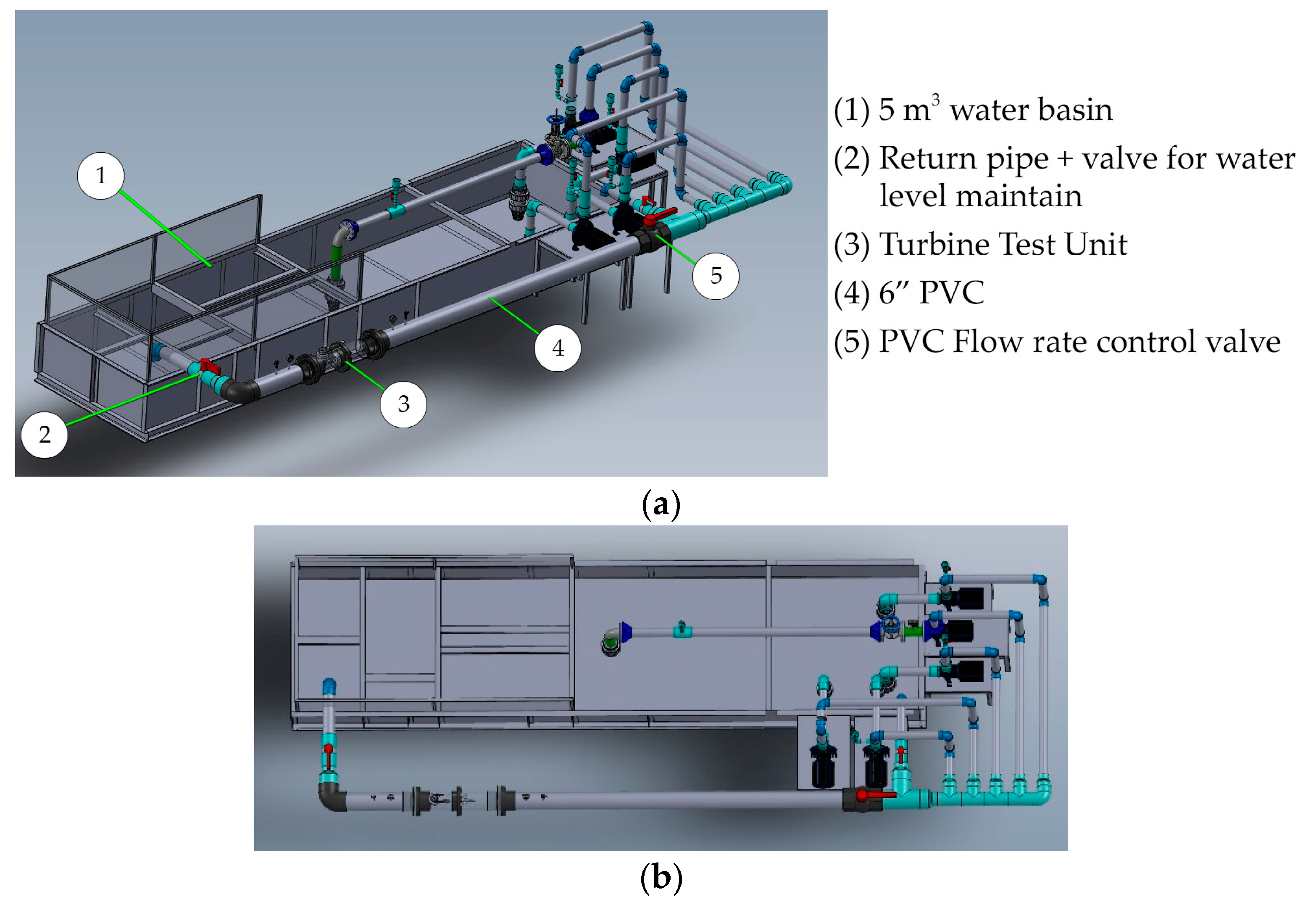
Figure 1. Sketch of the experimental setup. (a) Isometric view; (b) top view.
Energies 16 02267 g001
Figure 2. Simulation set.
Energies 16 02267 g002
Figure 3. Horizontal spiral turbine design.
Energies 16 02267 g003
Figure 4. Turbines to be tested in the simulations. (a) 18-degree, (b) 21-degree, (c) 3-blade.
Energies 16 02267 g004
Figure 5. Diffuser/collective chamber. (a) Three-dimensional representation; (b) drawing view.
Energies 16 02267 g005
Figure 6. The prototype and its components.
Energies 16 02267 g006
Figure 7. Two generator systems. (a) The generator system with a diffuser as a trumpet-shaped collective chamber. (b) The generator system with an in-line pipe + diffuser + nozzle chamber.
Energies 16 02267 g007
Figure 8. Field experiments. (a) The generator system with a diffuser as a trumpet-shaped collective chamber. (b) The generator system with an in-line pipe + diffuser + nozzle chamber.
Energies 16 02267 g008
Figure 9. Comparison results of efficiency of the three turbine types in laboratory simulation at water flow speed of 1, 1.25, 1.50, 1.75, and 2.00 m/s.
Energies 16 02267 g009
Figure 10. Comparison results of torque values of the three turbine types in laboratory simulation at water flow speed of 1, 1.25, 1.50, 1.75, and 2.00 m/s.
Energies 16 02267 g010
Figure 11. Comparison results of rpm generated by HST with 21-degree angle blade in the generator system with diffuser/collective chamber and the generator system with in-line + diffuser + nozzle chamber at water velocities of 1.0, 1.2, and 1.45 m/s.
Energies 16 02267 g011
Figure 12. Comparison results of power output generated by HST with 21-degree angle blade in the generator system with diffuser/collective chamber and the generator system with in-line + diffuser + nozzle chamber at water velocities of 1.0, 1.2, and 1.45 m/s.
Energies 16 02267 g012
Table 1. Turbine specifications [28].
ManufacturersDevice NameTurbine TypeMin./Max. SpeedPower Output
Lucid Energy Pty., Ltd. (Dallas, TX, USA) [29]Gorlov Helical turbineHelical Darrieus
cross-axis
(0.6 m/s)/no limitUp to 20 kW, depends on size
Thropton Energy Services
(Northumberland, UK) [30,31]
Water current turbineAxis flow
propeller
(0.6 m/s)/depends on diameterUp to 2 kW
at 240 V
Tidal EnergyPty., Ltd. (Canberra, Australia) [32]Davidson–HillVenturi (DHV) TurbineCross-flow
turbine
Min. 2 m/sFrom 4.6 kW
Seabell Int.Co., Ltd.
(Tokyo, Japan) [33]
SteamDual, cross-
axis
(0.6 m/s)/no limit0.5–10 kW
models
New Energy Corporation Inc. (Calgary, AB, Canada) [34]En Current
Hydro Turbine
Cross-axisMax. 3 m/s for maximum power5 kW
(and 10 kW)
Eclectic Energy Ltd.
(Nottinghamshire, UK) [35]
DuoGen-3Axial flow
propeller
Min. (0.93 m/s)/(4.63 m/s) max.8 amps
at 3.09 m/s
Alternative Hydro Solutions Ltd. (Toronto, ON, Canada) [31]Free-stream
Darrieus water turbine
Cross-axis(0.5 m/s)/depends on diameterUp to 2–3 kW
Energy Alliance Ltd.
(Ural region, Russia) [30]
Sub-merged
hydro unit
Cross-axisMin 3 m/s1–5 kW
(and 410 kW)
Table 2. Turbine specifications.
TurbineBlade Area (mm2)Pitch (mm)Length (mm)Width (mm)
18-degree12,653.7249233150
21-degree10,587.9149197150
3-blade754.96--10
Table 3. Axial flux generator specification.
Rated Power0.2 kW
Rated Rotation Speed200 rpm
Rated Voltage12VAC
Efficiency90%
Start Torque<0.05 Nm
Phase Type3 Phase
Table 4. Torque results.
TurbineSpeed of Turbine
(rpm)
Torque
(Nm × 100)
Water velocity (m/s) 1.21.2
Spiral turbine + collective chamber18-degree2813.65
21-degree4121.72
3-blade264.56
Spiral turbine + inline + collective chamber + inlet nozzle 100 cm18-degree10220.06
21-degree10828.40
3-blade587.04
Table 5. Power output results.
TurbineElectric Power (Watt)
Water velocity (m/s) 1.2
Spiral turbine + collective chamber18-degree21.90
21-degree28.43
3-blade6.92
Spiral turbine + inline + collective chamber + inlet nozzle 100 cm18-degree26.85
21-degree67.63
3- blade7.15
Table 6. Comparing results with related studies.
RefTurbineWater Velocity (V)Section Inlet Area (A)Work Output (Watt)
Wiroon21 deg spiral Turbine + diffuser1.45 m/s0.16 m267.63
Yasukuni Nishi et al. [41]3-blades + diffuser1.72 m/s0.16 m2154.00
Erinofiardi [54]Screw Turbine0.077 m/s0.0088 m20.28
Tomomi Uchiyama [12]Guide vane0.159 m3/s0.005 m2222.00
Joel Titus [55]Turbine blades0.009 m3/s0.005 m2212.00
Budiarso [56]Turgo turbinen.d.0.038 m25.34
C.H. Achebe [57]Crossflow turbine0.0015 m3/s0.015 m235.00
Gianluce Zitti et al. [49]Screw turbine1-2 m/s0.003 m2500.00
Table 7. A 200-watt hydro-compact generator with HST cost of production.
InventoryUSD per Unit
  • Turbine Cost of Production
429.31
2.
Materials Cost
572.41
3.
Generator Cost of Production
857.67
4.
Labor Cost
572.41
Remark: There will be variations in production cost since the cost has been converted from THB to USD (updated 15 December 2020).
Disclaimer/Publisher’s Note: The statements, opinions and data contained in all publications are solely those of the individual author(s) and contributor(s) and not of MDPI and/or the editor(s). MDPI and/or the editor(s) disclaim responsibility for any injury to people or property resulting from any ideas, methods, instructions or products referred to in the content.