Article

Research on Wellbore Integrity Assurance Technology for Deepwater High-Pressure Oil and Gas Wells

1
College of Safety and Ocean Engineering, China University of Petroleum, Beijing 102249, China
2
Drilling & Production Research Institute, CNOOC Research Institute Co., Ltd., Beijing 100028, China
3
China National Offshore Oil Corporation, Beijing 100020, China
*
Author to whom correspondence should be addressed.
Energies 2023, 16(5), 2230; https://doi.org/10.3390/en16052230
Submission received: 3 December 2022 / Revised: 12 January 2023 / Accepted: 13 January 2023 / Published: 25 February 2023
(This article belongs to the Section H1: Petroleum Engineering)

Abstract

:
Annulus pressure control is critical to well safety in deepwater oil and gas wells, and it is crucial for deepwater high-pressure oil and gas wells, which are related to production safety. At present, the deepwater annular pressure analysis model is mainly based on the trapped annulus principle. For the high annular pressure of deepwater high-pressure oil and gas wells, it brings great management and control challenges. This paper proposes a deepwater high-pressure oil and gas well annular pressure analysis method considering formation connectivity. According to the existing measures of annular pressure management and control, the differences between various types of annular pressure management and control technology are systematically analyzed and expounded, and the annular pressure management and control technology of deepwater high-pressure oil and gas wells is proposed accordingly. At the same time, combined with the actual case of a deepwater high-pressure well in the South China Sea, the annular pressure considering different influencing factors is analyzed, and the appropriate management and control methods of annular pressure are recommended. This paper systematically summarizes and studies the analysis and control technology of annular pressure in deepwater high-pressure oil and gas wells, which provides a technical basis for China’s deep water to move from conventional deepwater to deepwater high-pressure, and can provide a reference for the management and control of annular pressure in oil and gas wells in subsequent deepwater projects.

1. Introduction

The pace of global offshore oil and gas exploration and development has accelerated significantly, with the total amount of new offshore oil and gas discoveries exceeding that of land, and continued growth in reserves and production, which has become a strategic replacement area for global oil and gas resources. International Energy Agency data show that in the past decade, with the discovery of reserves of more than 100 million tons of large oil and gas fields, offshore oil and gas accounted for 60%, half of which is located in deepwater. At the same time, China has a vast ocean territory, and deepwater oil and gas resources are rich [1,2,3].
Due to the special characteristics of deepwater subsea Christmas trees and wellhead structures, the annular pressure between the casing cannot be released. Once the annular pressure rises beyond the strength limit of the string column, it will easily lead to casing extrusion and deformation, wellhead device failure, and even cause an uncontrolled blowout, resulting in huge economic losses and safety accidents. As shown in Figure 1, high annular pressure in deepwater oil and gas wells leads to casing crush and rupture. The trapped annular pressure has caused the abandonment of deepwater oil and gas wells in the Marlin field in the Gulf of Mexico, the Pompano A-31 stuck drilling accident, and the tubing deformation in the Mad Dog Slot oil and gas field W1 well [4,5,6]. In 2004 [4], D.W. Braddord, R.C. Rillis, and S.W. Gosch published a series of articles on the cause, well design, and prevention of the Marlin Field accident in the Gulf of Mexico. It is pointed out that in addition to the rapid decomposition of hydrate, spiral bending of tubing, and wellhead movement, the rapid rise of enclosed annulus pressure in the early stage of testing should be one of the main causes of the accident. In 2006 [5], P.D. Pattillo et al. analyzed the stuck drilling accident in the Pompano A-31 well in the Gulf of Mexico. It is pointed out that the drilling fluid carries heat up from the bottom of the well during the circulation process, causing thermal expansion of the liquid in the outer casing annulus, resulting in pressure in the closed annulus. The 16-inch casing is squeezed and deformed, resulting in a stuck drill string. In 2017, Marcus V. D. Ferreira et al. [7]. conducted a numerical simulation study on heat transfer behavior in the wellbore, considering that a change in the wellbore temperature field would cause pressure in the closed annulus. In 2014, Yin Fei and Gao Deli et al. [8] included the change of annular liquid expansion compressibility with temperature into the calculation model of annular pressure, which improved the prediction accuracy of annular pressure. Since 2013, Yang Jin et al. [9] have established a casing annulus pressure prediction model for deepwater oil and gas wells and adopted an iterative method to calculate multi-level annulus pressure. Therefore, the prediction and control of the well annulus pressure are of great significance for the safe development and production of deepwater oil and gas fields.
In recent years, with the rapid development of domestic deepwater oil and gas fields, the exploration and development of deep-water high-pressure oil and gas fields have entered from deep-water conventional oil and gas fields. Most previous studies have focused on the prediction and prevention of annulus pressure in conventional deepwater oil and gas fields. In order to more accurately predict and control annulus pressure in deep-water high-pressure oil and gas fields, this paper studies the source and necessary conditions of annulus pressure in deep-water wells based on the analysis of the well structure of typical deep-water wells and the structural characteristics of underwater wellhead devices. This paper analyzes the change law of annulus fluid thermodynamic performance with temperature, establishes the prediction model of annulus pressure in a deepwater high-pressure oil and gas field under the action of multi-annulus, analyzes the measures to control annulus temperature rise and pressure control, and recommends the suitable annulus pressure control method based on specific engineering cases.

2. Basic Methods for Annular Pressure Analysis in Deepwater Oil and Gas Wells

2.1. Basic Equation of Wellbore Temperature Field

According to the mechanism of heat transfer, heat transfer can be divided into three forms: heat conduction, heat convection, and heat radiation [10,11]. For deepwater oil and gas wellbore, heat conduction and heat convection are the two main methods [12,13,14,15].

2.1.1. Heat Conduction

Heat conduction, also referred to as thermal conductivity, is an instinctive property of matter. In 1822, the French mathematician Fourier first experimentally analyzed the phenomenon of thermal conductivity and summarily proposed the basic equation that reveals the problem of the thermal conductivity of objects, namely Fourier’s law. The mathematical expression is as follows:
Φ = λ A Δ T δ
Φ is the heat flow rate, representing the heat transferred unit time, W;
λ is the thermal conductivity, reflecting the magnitude of the object’s thermal conductivity, which is generally measured experimentally, W/(m°C);
A is the cross-sectional area perpendicular to the direction of heat conduction, m2;
δ is the thickness of the thermal conductor, m;
ΔT is the temperature difference between the two sides of the thermal conductor, °C

2.1.2. Heat Convection

During the testing and exploitation of deepwater oil and gas wells, the heat transfer between the high-temperature formation of viscous fluid inside the tubing and the inner wall of the tubing is classified as surface convective heat transfer. At present, the convective heat transfer coefficient inside the tubing still needs to be obtained experimentally, and the most widely used is the Dittus–Boelter formula, which applies to the empirical relationship between gas and low viscosity fluids in the case of a temperature difference between the medium wall and fluid:
N u f = 0.023 R e f 0.8 P r f n
Nuf is the Nussle number; Ref is the Reynolds number; Prf is the Prandtl number.

2.2. Fundamental Equation of Annular Pressure

The calculation of annular pressure is based on the PVT equation of state, and partial differentiation of the equation can be obtained as follows: [16,17]
Δ p a = α K T Δ T a 1 K T V a Δ V a + 1 K T V f Δ V f
α is the thermal expansion coefficient of the annular fluid, 1/℃;
K T is the isothermal compression coefficient of the annular fluid, 1/MPa;
Δ T a is the temperature change of the annular fluid, °C;
Δ V a is the volume change of the annulus, m3;
V a is the volume of annulus fluid, m3;
Δ V f is the volume change of annular fluid, m3;
V f is the volume of the annular fluid, m3.
The first term in the equation represents the value of the annular pressure increase caused by the thermal expansion of the annulus; the second term represents the annular pressure change caused by the volume change of the casing under the combined effect of temperature and pressure; and the third term represents the pressure change in the annulus caused by the volume change of the liquid in the annulus.
The PVT equation considers annulus pressure as a function of annulus temperature, volume, and annulus fluid mass, which can be expressed as:
p a = p a ( T a   ,     V a   ,   m )
The total increment differential of annular pressure pa at the point ( T a   ,     V a   ,   m ) can be expressed as:
d p a = ( p a T a ) Δ T a + ( p a   V a   ) Δ   V a   + ( p a m ) Δ m  
The isobaric expansion coefficient of annular liquid refers to the volume change rate of liquid with temperature under constant pressure, which can be expressed by definition as:
α = Δ V f V f Δ T a  
The isothermal compression coefficient of annular liquid refers to the volume change rate of liquid with pressure under constant temperature. Since the volume of liquid decreases when it is compressed, and the isothermal compression coefficient is positive, a negative sign needs to be added, which can be expressed as:
K T = Δ V f V f Δ P a  
In the initial state, the annulus volume of the closed annulus is equal to the annulus liquid volume, and thus:
V f = V a  
At constant volume, a rise in temperature will cause an increase in the volume of the liquid, and which at constant volume, will cause a rise in pressure. Therefore, the rise in unit temperature will cause a rise in pressure, and the change in liquid volume with pressure is negative, so:
( p a T a ) Δ T a = Δ V f V f Δ P a V f Δ P a Δ V f Δ T a = α K T Δ T a  
According to the production process of annulus pressure, the increase in annulus volume helps accommodate thermal expansion fluid. The derivation process is as follows:
( p a   V a   ) Δ   V a   = ( V f Δ P a Δ V f ) 1 V f Δ   V a   = 1 K T V a Δ V a  
The increase in annulus liquid mass will lead to an increase in pressure in the enclosed annulus. The derivation process is as follows:
( p a m ) Δ m = ( p a   V f   )   V f   = 1 K T V f Δ V f  
Equation (3) can be obtained by substituting Formulas (9)–(11) into formula (5).

3. Establishment of Annular Pressure Analysis Model for Deepwater High-Pressure Oil and Gas Wells

3.1. Classical Analysis Model of Annular Pressure

The current mainstream study of deepwater oil and gas well annular pressure is based on the volume compatibility principle of trapped annular pressure [10]. The principle of trapped annulus pressurization is similar to the ‘hydrothermal pressurization’ in geology, that is, after the wellbore is heated, the volume of the annulus and the liquid inside the annulus change at the same time, and the difference in thermal properties between the liquid and the casing makes it difficult for the volume of the annulus to accommodate the thermally expanded liquid, in order to meet the volume compatibility, the pressure rise in the annulus produces a compression effect on the liquid volume, so that the limited volume of the annulus can accommodate the thermally expanded liquid. Given that the annulus and the annulus liquid are in the exact same temperature and pressure field, the annulus liquid and the volume of the closed annulus always remain equal, that is, the volume change of both the same amount. According to the definition of the isobaric expansion coefficient, the increase in the volume of the annular air-liquid caused by warming can be expressed as follows:
Δ V f = Δ V a
According to the definition of the isobaric expansion coefficient, the volume increase of annulus liquid caused by a temperature rise can be expressed as follows:
Δ V f t = α 1 V f Δ T
Similarly, according to the definition of the isothermal compression coefficient, the volume reduction caused by annular pressure compression of annular liquid can be expressed as follows:
Δ V f p = K T V f Δ p
However, the casing is not completely rigid, and the annular volume of the wellbore will cause the deformation of the oil casing due to the action of the annular pressure, Δ V a can be derived from the elastic–plastic mechanical model [11], and the annular pressure can be expressed as follows:
Δ p = α 1 K T Δ T 1 K T V a Δ V a

3.2. Prediction Modeling of Annular Pressure Considering Formation-Cement Ring Permeability

Classical annular pressure analysis considers the annular space to be trapped, which is conservative and too demanding for deepwater wells, and sometimes it is difficult to select a suitable casing to meet the operational safety. At the same time, the formation of the annulus is dependent on the cementing agent. Due to the inherent characteristics of cementing cement, micro-gaps are often associated with the cement solidification process, resulting in leakage between the cement ring and formation. According to Darcy’s law analysis, it can be considered that the cement ring and the formation have equivalent permeability properties K g c , which is defined as the formation—cement ring equivalent permeability, then the annulus volume change caused by permeability can be expressed as follows:
  Δ V f = 10 6 K g c A C S μ d p d l
K g c is the formation—cement ring equivalent permeability, mD;
A C S is the contact area between stratum and cement ring, m2;
μ is dynamic viscosity, MPa · s ;
d p d l is pressure drop, MPa/m.
When considering the formation–cement ring permeability, the annulus pressure can be calculated by Formula (3); that is, the change in annulus volume is taken into account, and this method is more similar to the simulation of actual well conditions.

4. Research on Annular Pressure Control in Deepwater High-Pressure Oil and Gas Wells

Deepwater high-pressure oil and gas wells usually have higher bottomhole temperatures and higher production capacities than conventional deepwater oil and gas wells, so the management of annular pressure is more critical. After understanding the mechanism of pressure increase caused by annular trap closure, the main way to achieve annular pressure control is by controlling wellbore temperature change and volume change.

4.1. Annular Pressure and Temperature Control Method

There are usually two methods for annular pressure and temperature control, respectively, using insulated pipe and annular injection of insulated fluid.

4.1.1. Insulation Pipe

Thermal insulation pipe mainly refers to thermal insulation tubing and thermal insulation casing. The main principle is to control the thermal conductivity of the pipe, so that the temperature of the annulus can be effectively controlled after the use of thermal insulation pipe. However, the thermal insulation pipe only increases the thermal resistance of the heat conduction in the wellbore, making the temperature of the wellbore rise relatively slowly compared with that of the ordinary oil casing, so that the annular pressure can be controlled. To ensure that the full-life annular pressure of deepwater oil and gas wells is below the maximum allowable annular pressure, heat loss control at the joint of insulated tubing still requires improved insulation. According to the relevant literature, the regulation effect of insulated tubing has been simulated in indoor tests and studied and applied in deepwater oil and gas fields in Brazil, the Gulf of Mexico, and the South China Sea areas [17,18,19].

4.1.2. Annular Heat Insulation Fluid

The principle of heat insulation fluid injection into the annulus of deepwater oil and gas wells to control temperature rise is the same as that of heat insulation pipe. Especially when there are many layers of tubing and casing, injection through multi-layer casing can achieve better temperature control effect. According to literature research, the third generation of annular heat insulation fluid products has been formed, which has stable heat insulation performance, low corrosion, high temperature resistance, and also has good low temperature rheology during injection. At the same time, the annulus heat insulation fluid is solid free, which overcomes the problem of traditional drilling fluid solid deposition. It is widely used in deepwater oil and gas fields in the Gulf of Mexico because of its lower cost [20,21,22].

4.2. Annular Pressure Control Methods

The control of annulus pressure is mainly based on the volume-increment technology resulting from pressure leakage, including pressure relief valve technology, annulus compressible volume technology, and pressure relief technology for annulus pressure formation. At the same time, because of the special type of subsea wellhead used in deepwater oil and gas wells, supplementary pressure can also be used to ensure the safety of tubing and casing.

4.2.1. Pressure Relief Valve Technology

The pressure relief valve is a special tool installed on the casing nipple near the subsea wellhead, as shown in Figure 2. It automatically opens when the pressure difference between the inside and outside of the casing reaches the rated damage pressure of the pressure relief valve, balancing the pressure on both sides of the casing and creating a pressure release channel to the formation to protect the inner casing of the annulus. For the 35.56 cm and 50.80 cm casings with the risk of casing collapse, two casing pressure relief valves are installed on the upper part of the casing for mutual backup, and the two pressure relief valves are connected in a 180-degree distribution. In field use, the pressure relief valve is installed on the casing sub with the same size and steel grade as the casing string to facilitate field connection and running. The rated damage pressure of the pressure relief valve must be less than the extruding strength of the inner casing and the internal compression strength of the outer casing [23].

4.2.2. Annular Compressible Volume Technology

Annulus compressible technology is mainly used to add compressible materials into the annulus, as shown in Figure 3. At present, the main methods include adding hollow microspheres to isolation fluid, wrapping compressible foam material around casings, injecting compressible inert gas, etc.
A hollow microsphere is a kind of glass microsphere with a hollow structure and a diameter of 19.05~45 μm. According to different temperature changes and annulus structures, the rupture pressure of insulating glass microspheres can be adjusted, and the chemical properties and thermal stability are good. The release space can reach up to 40% of the annulus volume. When the pressure of the sealed annulus reaches the breaking pressure of the glass sphere, the glass sphere will break, releasing extra volume to contain the expanded annular liquid and reducing the annular pressure. In engineering applications, it is necessary to prevent the glass microsphere from breaking in advance under the pressure of the liquid column.
With the increase in pressure, the volume of compressible foam begins to shrink. When it is wrapped outside the casing, the space containing the expansion of annulus fluid can be released to prevent the growth of annulus pressure, thus achieving the purpose of reducing the pressure of the enclosed annulus. The volume change of compressible foam can be divided into elastic compression stage, smooth compression stage and compaction stage, and finally reach the volume shrinkage limit. The key to compressible foam technology is the volume shrinkage rate and working pressure of the material. At present, the volume shrinkage of compressible foam is generally greater than 30%, the maximum is 50%, the minimum working pressure is about 28 MPa, and the temperature resistance is up to 110 °C. It has been used in deepwater oil and gas wells in the Gulf of Mexico, the North Sea, and West Africa [24,25,26].
The principle of annulus injection of compressible inert gas is the same as that of compressible synthetic foam technology, which is to absorb excess pressure by increasing the space of the closed annulus. The current common practice is to inject a certain percentage of nitrogen into the annulus to break the plug because the isothermal compression coefficient is much greater than that of the annulus liquid. The annular pressure decline slows as the volume of nitrogen foam is increased, and a relatively small amount of nitrogen (<5% of the volume of the annulus) can absorb enough added annulus pressure to prevent casing failure.

4.2.3. Pressure Relief Technology of Annular Pressure Formation

Annular pressure is created because the layers of casing cement slurry flow up into the upper casing, creating a trapped space. If there is no zone that must be sealed, the cement return height can also be controlled to allow the annulus to connect to the drilled formation, providing a possible channel for pressure relief. At the same time, it is necessary to consider that in the long term, the solid phase content in the packer fluid inside the annulus will continue to accumulate, so the reserved annulus space can avoid the pressure release requirement after solid phase compaction. In theory, the accumulation of annular pressure on the upper casing shoe or the fracture pressure in the weak zone of the exposed well will release the annular pressure generated by the trap into the formation. The maximum annular pressure is as follows:
p f m a x = p f
p f m a x is the maximum annulus pressure, MPa;
p f   is the fracture pressure at the upper casing shoe or the weak zone in the exposed well section, MPa.
A annular pressure relief/replenishment technology.
Because of the special structure of the subsea wellhead and subsea Christmas tree, it is impossible to detect and manage the pressure of the casing annulus at each level in deepwater oil and gas wells as it is in onshore wells. Figure 4 and Figure 5 are the schematic diagrams of annular pressure detection and management methods for horizontal and vertical subsea Christmas trees, respectively.
In the process of deepwater drilling and completion, the surface conductor is usually verbally fixed with conductor housing and run by injection. The surface casing is verbally fixed to the wellhead housing, run through drilling, and then the well is sealed and cemented. After each opening, the casing is directly hung inside the wellhead housing, and the double sealing method of metal-to-metal and rubber-to-metal is adopted for strict sealing [27,28,29,30]. Therefore, after the installation of the subsea wellhead and subsea Christmas tree, only the A annulus between the tubing and the production casing can adjust the pressure. The annulus pressure is mainly detected by the pressure sensor under the A annulus main valve and the umbilical annulus pressure line. At the same time, the pressure is managed by the A annulus main valve, the annulus entry valve, or the chemical injection line. Other casing annuli cannot be managed.
For deepwater oil and gas wells, the A annulus can either release pressure or supplement pressure. The principle is to maintain appropriate pressure to ensure the operational safety of each casing.

4.3. Recommended Methods for Annular Pressure Management in Deepwater High-Pressure Oil and Gas Wells

Deepwater high-pressure oil and gas wells have a higher production layer temperature than conventional deepwater wells, which makes it more difficult to manage the annulus. In general, high-specification casing is needed to meet the requirements of annulus pressure management. In view of the annulus temperature control and annulus pressure control methods proposed above, the advantages and disadvantages of different management methods are introduced in detail. Moreover, considering the application range, reliability, operating cost, and other factors, the annulus pressure control measures suitable for deepwater high-pressure oil and gas fields are recommended, as shown in Table 1.
According to the analysis results in Table 1, the annular pressure formation relief technology is most applicable when the formation conditions permit. In addition, the installation of pressure relief valves and compressible foam is more suitable for the management of annular pressure in deepwater high-pressure oil and gas wells.

5. Engineering Case Analysis

5.1. Basic Information of Deepwater High-Pressure Oil and Gas Wells

A deepwater deep well X-1 in the South China Sea, water depth 957.3 m, well depth 5379.89 m, reservoir temperature 138.5 °C, reservoir pressure 60 MPa, casing data of each layer are shown in Table 2. According to the well passing oil, gas, and water formations, the cement return height of 339 mm casing is 1966 m (2166 m is the top of the passing gas formation), and the cement return height of 245 mm casing is 4400 m (4450 m is the top of the passing water formation). Moreover, a 660 mm borehole adopts a seawater/general earth slurry and CaCl2 polymer brine bedding slurry; a 406 mm borehole adopts a synthetic drilling fluid system; a 311 mm borehole adopts a synthetic composite drilling fluid system; and a 215 mm borehole adopts a water-based drilling fluid system.

5.2. Fundamental Analysis of Annular Pressure

The inclination angle at the 508 mm casing shoe of well X-1 is 20°, and the inclination angle at the 339 mm casing shoe is 55°. According to the analysis of solid phase content in the casing drilling fluid of each layer, the 508 mm casing and 339 mm casing annulus still have 168 m annulus space to connect with the formation after long-term solid-phase settlement. The 339 mm casing and 245 mm casing annulus still have 359 m annulus space to connect to the formation after long-term solid-phase settlement. However, considering the influence of the well inclination angle, in order to ensure lifetime wellbore safety, it is conservatively believed that the 508 mm casing and 339 mm casing annulus can connect the release pressure with the formation, while the 339 mm casing and 245 mm casing annulus cannot connect the release pressure with the formation, that is, the B annulus is considered as the trap space.
In order to ensure the accuracy of wellbore temperature field prediction, two mainstream software programs, the well string design and analysis software Wellcat and the full-dynamic multiphase flow simulation calculation software OLGA, were used for simulation analysis. Taking the wellhead temperature at the initial stage of production as an example, the temperature analysis results were 98.2 °C and 98 °C, respectively. The wellbore temperature profile for subsequent annular pressure analysis is shown in Figure 6.

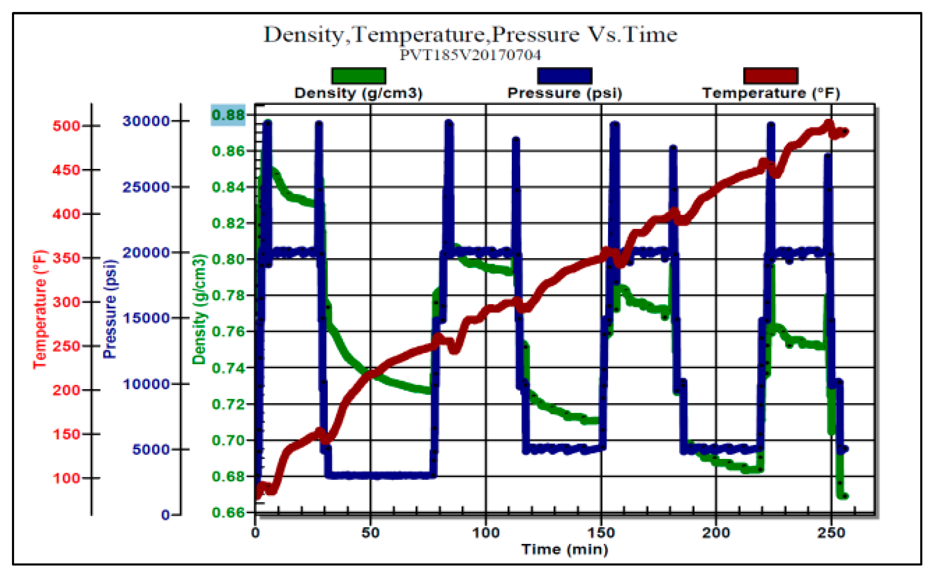
5.3. Influence Analysis of PVT Characteristics of Annular Isolation Fluid

The PVT characteristics of annular isolation fluid are crucial for an accurate analysis of annular pressure [31]. Sensitivity analysis is carried out in two cases: one considers the expansion coefficient/pressure number coefficient of annular isolation fluid as a constant value; and the other considers the change in the expansion coefficient/pressure number coefficient of annular isolation fluid with PVT, as shown in Figure 7. The analysis results are shown in Table 3. Considering that the change in the expansion coefficient/pressure number coefficient of the annular isolation fluid with PVT has a great influence on the annular pressure, the difference between the two analysis results is about 20 MPa. Therefore, the influence of the PVT characteristics of the annular isolation fluid must be considered in the subsequent analysis of the annular pressure.
As can be seen from Table 3, when the expansion coefficient/compression coefficient of annulus isolation fluid changes with PVT, the annulus pressure changes significantly. Compared with the constant expansion coefficient/compression coefficient, the difference between the two annulus pressure results is about 20 MPa. Therefore, the subsequent analysis of annulus pressure must consider the influence of the PVT characteristics of the annulus isolation fluid.
This is mainly because the thermal expansion coefficient of the annulus fluid is the dominant factor in generating fluid thermal expansion pressure. Under the same temperature change, the larger the thermal expansion coefficient is, the higher the volume expansion rate is, and the larger the annulus pressure is generated. Therefore, reducing the thermal expansion coefficient of the annulus fluid can better control the annulus pressure rise. Under the same pressure change, the larger the isothermal compression coefficient is, the higher the volume compression ratio is, and the smaller the annular pressure is generated. Therefore, increasing the isothermal compression coefficient of annulus fluid can better control the rise in annulus pressure.

5.4. Analysis of Annular Pressure and Control Method

According to the situation of well X-1, annular pressure formation relief technology can be used to control annular pressure in the C annulus, and annular pressure relief/recharge technology can be used to control annular pressure in the B annulus. Annular pressure analysis can be carried out in three working conditions at different stages of production: initial, middle, and late stage. The analysis results are shown in Table 4. The analysis shows that the selected casing strength can meet the production safety requirements under the pressure control of the A annulus, that is, the absolute pressure control range of the A annulus is 25–35 MPa. At the same time, in order to ensure the safety of annulus B, the annulus compressible volume technology can be assisted. According to Section 4.3 of this paper, the compressible foam method is recommended.
A compressible foam material is installed outside the casing to reduce the additional casing load caused by temperature. A certain amount of compressible foam material is installed on the inner casing. When the annular pressure increases to a certain extent, the compressible foam material begins to deform, creating a certain space for fluid expansion, which reduces the annular pressure. The compressible foam material is installed on the inner casing in a modular manner. Considering the convenience of running the casing, the compressible foam module is only installed on the casing body and not on the casing joint.

6. Conclusions and Suggestions

This paper introduces deepwater high-pressure oil and gas well annular pressure analysis and control technology and achieves the following main conclusions and recommendations:
The causes of annulus pressure in deep water oil and gas wells are analyzed. Annulus pressure is caused by the redistribution of the temperature field in oil and gas wells. The contradiction between the limited volume of enclosed annulus and the thermal expansion of annulus liquid is the fundamental cause of annulus pressure rise. Two basic conditions are required for its generation: one is the heat source of the annular temperature field change; the second is the closed space containing liquid. According to the characteristics of complex well structures and multiple annulus layers in deepwater oil and gas wells, a suitable annulus pressure analysis method is established according to the principle of volume compatibility.
The advantages and disadvantages of different annulus pressure management methods are systematically analyzed, and the annulus pressure management methods suitable for deepwater high-pressure oil and gas wells are presented. Combined with the specific analysis and research of well X-1, the compressible foam volume method is recommended, the annulus pressure management technology of annulus pressure formation is adopted for annulus pressure management in the C annulus, and the annulus pressure relief/supplementary technology of the A annulus is adopted for annulus pressure management in the B annulus.

Author Contributions

Conceptualization, J.Z.; data curation, J.Y.; formal analysis, Y.W. and G.X.; investigation, T.Z.; methodology, J.Y.; project administration, X.Z. (Xin Zou).; resources, J.Z.; validation, X.Z. (Xingquan Zhang); writing—original draft, Y.W.; writing—review and editing, T.Z. All authors have read and agreed to the published version of the manuscript.

Funding

This research received no external funding.

Data Availability Statement

Not applicable.

Conflicts of Interest

The authors declare no conflict of interest.

References

  1. Research Institute of Petroleum Exploration and Development. Global Oil and Gas Exploration and Oil Company Dynamics. Fault-Block Oil Gas Field 2017, 24, 792. [Google Scholar]
  2. Zhang, G.C.; Qu, H.J.; Zhao, C.; Zhang, F.L.; Zhao, Z. Giant discoveries of oil and gas exploration. Nat. Gas Geosci. 2017, 28, 1447–1477. [Google Scholar]
  3. Yang, L.; Wang, L.; Pan, J. Situation and Prospect of global deepwater oil and gas exploration and development. China Min. Mag. 2017, 26, 14–17. [Google Scholar]
  4. Bradford, D.W.; Fritchie, D.G.; Gibson, D.H.; Gosch, S.W.; Pattillo, P.D.; Sharp, J.W.; Taylor, C.E. Marlin failure analysis and redesign:part 1-description of failure. SPE Drill. Complet. 2004, 19, 101–104. [Google Scholar] [CrossRef]
  5. Pattillo, P.D.; Cocales, B.W.; Morey, S.C. Analysis of an annular pressure buildup failure during drill ahead. SPE Drill. Complet. 2006, 21, 242–247. [Google Scholar] [CrossRef]
  6. Pattillo, P.D.; Sathuvalli, U.B.; Rahman, S.M.; Prewett, H.H.; Carmichael, S.P.; Wydrinski, R. Mad Dog Slot W1 Tubing Deformation Failure Analysis; SPE: Los Angeles, CA, USA, 2007; p. 109882. [Google Scholar]
  7. Ferreira, M.V.; Hafemann, T.E.; Barbosa, J.R.; da Silva, A.K.; Hasan, R. A Numerical Study on the Thermal Behavior of Wellbores. SPE Prod. Oper. 2017, 31, 564–574. [Google Scholar] [CrossRef]
  8. Yin, F.; Gao, D. Improved Calculation of Multiple Annuli Pressure Buildup in Subsea HPHT Wells; IADC/SPE: Bangkok, Thailand, 2014; p. 170553. [Google Scholar]
  9. Liu, B.; Yang, J.; Zhou, B.; Yan, D.; Tian, R.; Liu, Z.; Luo, J.; Huang, X. Study of Casing Annulus Pressure for Deepwater Drilling and Completions; SPE: Houston, TX, USA, 2014; p. 170318. [Google Scholar]
  10. Zhang, B.; Guan, Z.; Zhang, Q. Prediction and analysis on annular pressure of deepwater well in the production stage. Acta Pet. Sin. 2015, 36, 1012. [Google Scholar]
  11. Zhang, B.; Zhichuan, G.U.; Sheng, Y.; Qing, W.A.; Chuanbin, X.U. Impact of wellbore fluid properties on trapped annular pressure in deepwater wells. Pet. Explor. Dev. 2016, 43, 869–875. [Google Scholar] [CrossRef]
  12. Hasan, A.R.; Kabir, C.S.; Wang, X. Wellbore Two-Phase Flow and Heat Transfer During Transient Testing. SPE J. 1998, 3, 174–180. [Google Scholar] [CrossRef]
  13. Hu, Z. Research on the Risk Assessment and Prevenrion Methods of Annular Pressure Buildup in Deepwater Wells; China University of Petroleum: Beijing, China, 2019. [Google Scholar]
  14. Liu, J. Research on the Annular Pressure Buildup and Mitigation Mechanism in Deepwater Wells; China University of Petroleum: Beijing, China, 2017. [Google Scholar]
  15. Zhang, B. Prediction and Mitigation Mechanism of Casing Annular Pressure in Deepwater Wells; China University of Petroleum: Beijing, China, 2018. [Google Scholar]
  16. Williamson, R.; Sanders, W.; Jakabosky, T.; Serio, M.; Griffith, J.E. Control of Contained-Annulus Fluid Pressure Buildup; SPE: Amsterdam, The Netherlands, 2003; p. 79875. [Google Scholar]
  17. Gosch, S.W.; Horne, D.J.; Pattillo, P.D.; Sharp, J.W.; Shah, P.C. Marlin failure analysis and redesign: Part 3-VIT completion with real-time monitoring. SPE Drill. Complet. 2004, 19, 120–128. [Google Scholar] [CrossRef]
  18. Azzola, J.H.; Tselepidakis, D.P.; Pattillo, P.D.; Richey, J.F.; Tinker, S.J.; Miller, R.A.; Segreto, S.J. Application of Vacuum Insulated Tubing to Mitigate Annular Pressure Buildup. SPE Drill. Complet. 2007, 22, 46–51. [Google Scholar] [CrossRef]
  19. Ezzat, A.M.; Miller, J.J.; Ezell, R.; Perez, G.P. High-Performance Water-Based Insulating Packer Fluids; SPE: Los Angeles, CA, USA, 2007; p. 109130. [Google Scholar]
  20. Horton, R.L.; Froitland, T.S.; Foxenberg, W.E.; Knox, D. A New Yield Power Law Analysis Tool Improves Insulating Annular Fluid Design; IPTC: Doha, Qatar, 2005; p. 10006. [Google Scholar]
  21. Eriksen, K.; Panamarathupalayam, B.; Foxenberg, W.E.; Chumakov, E. A Novel High Temperature Insulating Packer Fluid (Russian); SPE: Moscow, Russia, 2014; p. 171284. [Google Scholar]
  22. Javora, P.H.; Pearcy, R.; Wang, X.; Stevens, D.; Qu, Q. A Decade of Experience: The Water Based Thermal Insulating Packer Fluid; SPE: Denver, CO, USA, 2008; p. 116769. [Google Scholar]
  23. Sathuvalli, U.B.; Pilko, R.M.; Gonzalez, R.A.; Pai, R.M.; Sachdeva, P.; Suryanarayana, P.V. Design and Performance of Annular-Pressure-Buildup Mitigation Techniques. SPE Drill Compl. 2017, 32, 168–183. [Google Scholar] [CrossRef]
  24. Wu, Y. Study on the Simplification Technology of Surface Casing in Deepwater Drilling. China Pet. Mach. 2017, 45, 53–56. [Google Scholar]
  25. Bo, Z.H.; Jin, Y.; Zhengli, L.I.; Junfeng, L.U.; Huang, X.; Rongxin, Z.H.; Yu, S.O. Mechanism of pressure management by injecting nitrogen in casing annulus of deepwater wells. Pet. Explor. Dev. 2015, 42, 422–426. [Google Scholar]
  26. Bailing, Z.H.; Jin, Y.A.; Xiaolong, H.U.; Zhiqiang, H.U.; Li, H.E. Adaptability evaluation of calculation model of annular pressure of deepwater wellbore. Oil Drill. Prod. Technol. 2015, 37, 56–59. [Google Scholar]
  27. Wu, Y.; Yang, C.; Liu, S.; Fan, B.; Cheng, Z.; Du, J. Development of multi-body dynamic solver for offshore drilling risers. Shipbuild. China 2019, 60, 83–90. [Google Scholar]
  28. Kan, C.; Yang, J.; Yu, X. Heat-insulated testing string technology for deepwater HTHP wells. Oil Drill. Prod. Technol. 2016, 38, 796–800. [Google Scholar]
  29. Huang, X.; Yan, D.; Tian, R.; Liu, Z.; Ye, J.; Fang, M.; Zhang, X. Analysis of trap pressure calculation and control technology in deep casing annulus. China Offshore Oil Gas 2014, 26, 61–65. [Google Scholar]
  30. Zhao, W.; Leng, X.; Chen, B.; Mu, X.; Ener Tech-Drilling & Production Co., CNOOC; Shenzhen Branch, CNOOC. Discussion the Method of Monitoring and Diagnostic Method for Annular Pressure Buildup in Deepwater Well. Oil Field Equip. 2016, 45, 5–10. [Google Scholar]
  31. Ilyushin, Y.V.; Fetisov, V. Experience of virtual commissioning of a process control system for the production of high-paraffin oil. Sci. Rep. 2022, 12, 18415. [Google Scholar] [CrossRef] [PubMed]
Figure 1. Schematic diagram of casing collapse caused by excessive annular pressure in deepwater oil and gas wells.
Energies 16 02230 g001
Figure 2. Schematic of casing sub with broken ring installed.
Energies 16 02230 g002
Figure 3. Schematic installation with compressible foam casing.
Energies 16 02230 g003
Figure 4. The diagram of pressure detection and management in each annulus of subsea horizontal tree.
Energies 16 02230 g004
Figure 5. The diagram of pressure detection and management in each annulus of subsea vertical tree.
Energies 16 02230 g005
Figure 6. Analysis results of wellbore temperature field in well X-1.
Energies 16 02230 g006
Figure 7. PVT characteristics of annular spacer in well X-1.
Energies 16 02230 g007
Table 1. Comparison and analysis of annular pressure control methods.
Control MeasuresTechnical
Advantages
Technical
Disadvantages
Scope of
Application
ReliabilityCost of
Operations
Annular temperature controlInsulation pipeHigh requirements for on-site operationHigh thermal conductivity at the junctionWideMediumHigh
Annulus insulation fluidConvenient on-site operationLimited isolation rangeWideMediumMedium
Annular pressure controlInstall pressure relief valveEasy installationDamage to well integrity; High requirement for formation pressure prediction; The risk of solid phase precipitation being buried; Limited pressure test and well controlWideMediumLow
Hollow microsphere isolation fluidConvenient on-site operationPrevent glass microspheres from breaking early under the pressure of liquid columnWidePoorMedium
Compressible foamEnsure well integrity, wide range of pressure control options, and high requirements for on-site construction sitesUnable to recover, easy to cause vacuumWideHighHigh
Inject compressible inert gasEnsure well integrity, wide range of pressure control options, and high requirements for on-site construction sitesNitrogen leaks easily; Too much pressure turns into liquid nitrogenLowHighHigh
Pressure relief technology of annular pressure formationAnnular pressure problem partially solved; cementing relatively easyNeed to measure cement return; The solid phase content of drilling fluid easily causes trap spaceHighHighLow
A annular pressure relief/replenishment technologyEasy to operateThe pressure of B and C annulus is unknown and the control range is limitedMediumMediumLow
Elimination of annulusComplete sealing and cementingRoots on solve the problem of annulus with pressure, without managementDeepwater cementing is difficult or impossible; Easy to cause the sealing assembly and BOP cement contact brings complex situationLowLowMedium
Table 2. X-1 well basic information data sheet.
NameOutside
Diameter m
Wire Weight
kg/m
Steel GradeDepth
m
Conductor914351.3X561072.7
Surface casing508197.9X561700
Technical casing339101.2P1103385
Production casing24579.6P1105170
Liner17847.6P1104600–5375
Tubing11422.6P1105300
Table 3. Influence analysis on PVT characteristics of annular isolator in well X-1.
StringAnnulusExpansion Coefficient/Compression Coefficient is ConstantExpansion Coefficient/Compression Coefficient Varies with PVT
Top DepthBottom DepthTrapFluidTrapFluid
mmPressureVolumePressureVolume
MPam3MPam3
339 mm casing
(C annulus)
957.719669.514.539.514.51
245 mm casing
(B annulus)
957.7440057.874.2937.584.3
114 mm tubing
(A annulus)
957.7492070.322.0166.081.99
Table 4. Analysis of annular pressure and control mode in well X-1.
Working ConditionStringAnnulusInitial ProductionMedium ProductionLate Production
Top
Depth
m
Bottom
Depth
m
Trap
Pressure
MPa
fluid
Volume
m3
Trap
Pressure
MPa
fluid
Volume
m3
Trap
Pressure
MPa
Fluid
Volume
m3
A annular pressure not managed339 mm
Casing
C annulus
957.719669.514.519.512.839.512.12
245 mm casing
B annulus
957.7440037.584.325.662.821.12.26
114 mm tubing
A annulus
957.7492066.081.9946.081.3538.411.12
A annular pressure management (APB = 15 MPa)339 mm
Casing
C annulus
957.719669.514.519.512.839.512.12
245 mm casing
B annulus
957.7440033.344.323.072.819.132.26
114 mm tubing
A annulus
957.74920151.99151.35151.12
A annular pressure management (APB = 25 MPa)339 mm
Casing
C annulus
957.719669.514.519.512.839.512.12
245 mm casing
B annulus
957.7440034.164.323.92.819.972.25
114 mm tubing
A annulus
957.74920251.99251.35251.12
Disclaimer/Publisher’s Note: The statements, opinions and data contained in all publications are solely those of the individual author(s) and contributor(s) and not of MDPI and/or the editor(s). MDPI and/or the editor(s) disclaim responsibility for any injury to people or property resulting from any ideas, methods, instructions or products referred to in the content.

