Review

A Comprehensive Assessment of Two-Phase Flow Boiling Heat Transfer in Micro-Fin Tubes Using Pure and Blended Eco-Friendly Refrigerants

by
Neeraj Kumar Vidhyarthi
1,
Sandipan Deb
1,
Sameer Sheshrao Gajghate
2,
Sagnik Pal
1,
Dipak Chandra Das
1,
Ajoy Kumar Das
1 and
Bidyut Baran Saha
3,4,*
1
Department of Mechanical Engineering, National Institute of Technology Agartala, Jirania, Agartala 799046, Tripura, India
2
Department of Mechanical Engineering, G H Raisoni College of Engineering and Management, Pune 412207, Maharashtra, India
3
International Institute for Carbon-Neutral Energy Research (WPI-I2CNER), Kyushu University, Fukuoka 819-0385, Japan
4
Department of Mechanical Engineering, Kyushu University, 744 Motooka, Nishi-ku, Fukuoka 819-0385, Japan
*
Author to whom correspondence should be addressed.
Energies 2023, 16(4), 1951; https://doi.org/10.3390/en16041951
Submission received: 24 January 2023 / Revised: 8 February 2023 / Accepted: 10 February 2023 / Published: 16 February 2023
(This article belongs to the Special Issue Heat Transfer Enhancement in Heat Exchangers)

Abstract

:
This review study examines flow boiling heat transfer in micro-fin tubes using mixed and pure refrigerants with zero ozone-depleting potential (ODP) and minimal global warming potential (GWP). This investigation focuses on the extraordinary relationship between heat transfer coefficients (HTCs) and vapor quality. Since the introduction of micro-fin heat exchanger tubes over 30 years ago, refrigerant-based cooling has improved significantly. Air conditioning and refrigeration companies are replacing widely used refrigerants, with substantial global warming impacts. When space, weight, or efficiency are limited, micro-fin heat exchangers with improved dependability are preferred. This review article discusses flow boiling concepts. The researchers used several refrigerants under different testing conditions and with varying micro-fin tube parameters. Micro-fin tubes are promising for improved heat transfer techniques. This tube increases the heat transfer area, fluid disturbance, flow speed, and direction owing to centrifugal force and HTC. As the focus shifts to improving heat transfer, pressure drop, mean vapor quality, and practical devices, this subject will grow more intriguing. A radical shift will reduce equipment size for certain traditional heat transfer systems and bring new products using micro-scale technologies. This suggested review effort helps comprehend saturation flow boiling through micro-fin tubes and find the right correlation for a given application. This domain’s challenges and future relevance are also discussed.

1. Introduction

The refrigerant is a vital element of any refrigeration or air conditioning system. The effectiveness of the refrigeration process or cooling effect depends on the properties of the refrigerant being used. The properties, such as thermophysical properties, environmental properties, and safety precautions, are essential to know before using any refrigerant. Many researchers [1,2,3] discussed the good-to-fit properties of a refrigerant. Majorly discussed is the environmental effect of the refrigerant being used. Several refrigerants are there to impact the environment negatively since they cause ozone layer depletion and global warming [4,5,6,7,8,9]. Specific terminologies are used for them, such as Ozone Depletion Potential (ODP) and Global Warming Potential (GWP), respectively. ODP is the latent quality to end the existence of the ozone layer, whereas GWP is the equivalent measure for the greenhouse gases emitted from the refrigerant [10,11,12,13,14]. Using a low-grade GWP refrigerant with minimal ODP, matching thermal qualities, and chemical stability are crucial. Hydro-chlorofluorocarbons (HCFCs) are mostly to blame for raising the halogen level in the atmosphere, which indirectly contributes to the thinning of the ozone layer [15]. There is a model of the corporation known as the Montreal Protocol to protect the ozone layer [6]. It promotes alternatives to refrigerants that affect the environment and suggests using refrigerants with low GWP to phase out HCFCs. Additionally, employing a low-efficiency refrigerant during the refrigeration process results in the generation of carbon dioxide (CO2), a greenhouse gas that contributes to global warming. So, for low GWP, the refrigerant should possess high efficiency. The researchers have utilized the different generations of refrigerant for experiments to cooperate with existing environmental protocols, as shown in Figure 1.
Many researchers [16,17] suggested that refrigerants were less harmful in closed systems compared to open systems due to less exchange of matter in closed systems. The basic thermophysical properties of pure and blended refrigerants are given in Table 1 from the ASHRAE handbook [18].
When a refrigerant is used in the refrigeration cycle, its phase changes from liquid to vapor by evaporation or boiling. In addition to this, the process of boiling has been addressed. There are different kinds of boiling processes, such as pool boiling and flow boiling. Pool boiling is related to natural convection heat transfer, and flow boiling is related to forced convection heat transfer [19]. Here, employing different refrigerants across a horizontal micro-fin tube to examine how flow boiling affects heat transfer efficiency is the main goal of this study. So, in this connection, two schematic diagrams [20] for flow patterns and heat transfer regions at the horizontal position in flow boiling are shown in Figure 2. Figure 2 shows the different flow patterns in single (liquid only) and the fluid’s two-phase flow (liquid + gas). As the flow progresses, the generated bubbles in bubbly flow start colliding with each other and obtain a form of bullet-like bubble, also known as Taylor’s bubble in slug flow. Further, it moves forward, and the liquid generates a thin layer on the walls and converts into the annular flow. Some droplets of liquid further appear in the gaseous region, and thus it is called dispersed annular flow. At last, the droplets are in the gaseous region, called droplet flow. Further, in Figure 2, the various heat transfer regions can be seen. In different sectors, such as Refrigeration and Air Conditioning (RAC), nuclear reactors and aircraft put together heat transfer, an essential factor to study. At the first region, natural convection heat transfer occurs where bubbles are generated, and the single-phase flow starts to be two-phase. The HTC of two-phase flow is higher than that of single-phase flow at the same working conditions [21,22,23].
Further, in sub-cooled boiling, the collision of bubbles occurs under the saturation temperature. After the collision, a giant bubble is formed at the saturation temperature of saturated nucleate boiling. Further, a forced convection heat transfer occurs mainly at dispersed annular flow. Last is the deficiency of liquid, named the liquid deficient region.
Figure 3 depicts an interdependency of the flow boiling with different parameters. Flow boiling occurs when a fluid moves continuously over a heated surface through an external force, such as a pump or due to the natural buoyancy effect [24,25,26,27,28]. The flow pattern’s characteristics like flow field and flow regimes transition, dependent upon the geometry of the channel or tube and the thermophysical properties of the fluid [27,28,29,30,31,32,33]. The wall temperature of the tube is an essential parameter in the study of any boiling. Heat transfer enhancements are done to reduce the wall temperature for any experimental study; proper insulation of the experimental setup is vital for better results and findings. The saturation temperature is critical in studying heat transfer; as shown in Figure 3, the saturation temperature is the one parameter to distinguish between significant regions in heat transfer in flow boiling. Parameters regarding tube characteristics, such as tube length and diameter, are also essential because the requirement of minimizing the technologies’ sizes and improving capacities have been demanded, and the equipment sizes are anticipated to lessen in microns [6]. The worldwide applications of micro-technologies in the last five decades unite the production of maximum HTC and the claims of refrigeration systems, i.e., highly effective, lessened in size, and well-matched with the systems. The main input parameters in any boiling are heat flux, mass flux, vapor quality, and blends with oil or more than one refrigerant. Therefore, many researchers considered these input parameters at different ranges for different experiments. It is crucial to consider the single-phase flow and the two-phase flow because these are essential parameters to better understand flow boiling [34]. Two-phase flow depends on tube geometry, such as bends, spirals, corrugated plates, enhanced surfaces (micro-fins or grooves), flow patterns, and refrigerants. Many researchers have already discussed the smooth tube with different inner diameters [35,36,37,38,39,40,41,42,43] to obtain the output parameters, such as HTC and pressure drop.
Fins play a critical role in increasing the total surface area available for heat transfer [44]. It is possible to transform a plain (smooth) tube into a micro-fin tube by adding micro-fins on the interior side of the plain tube. A micro-finned tube was invented by Fujie et al. [45]. These micro-fins provide a larger surface area for heat transfer, increasing the HTC and the pressure drop. It was demonstrated by many researchers [46,47,48] using a variety of refrigerants and input parameter ranges. The researchers utilized the terminology “enhanced factor,” which refers to the ratio of HTC in the micro-fin tube to HTC in the plain tube, to compare both types of tubes [49]. Many researchers do the initial developments in the designs of the micro-fin tubes. Many researchers [50,51] experimentally discussed their designs of micro-fin tubes to enhance the HTC locally inside the tube.
Some review papers talk about ways to improve flow boiling heat transfer, while others only talk about flow boiling models. None of the review papers that have already been published talk about both pure and mixed refrigerants together. The purpose of this review paper is to provide context for recent studies of flow boiling using pure and mixed refrigerants within horizontal micro-fin tubes and to suggest directions for further study in this area. The sections that follow will cover a variety of subjects of relevance. First, the need to investigate methods to improve heat transfer is discussed. The most current findings from studies of heat transfer in micro-fin tubes using natural and mixed refrigerants for flow boiling are then presented. Finally, this article presents an overview of the state of art in developing analytical models of flow boiling in micro-fin tubes using pure and mixed refrigerants. Research directions for pure and mixed refrigerants boiling within horizontal micro-finned tubes are described after a review of the relevant literature.

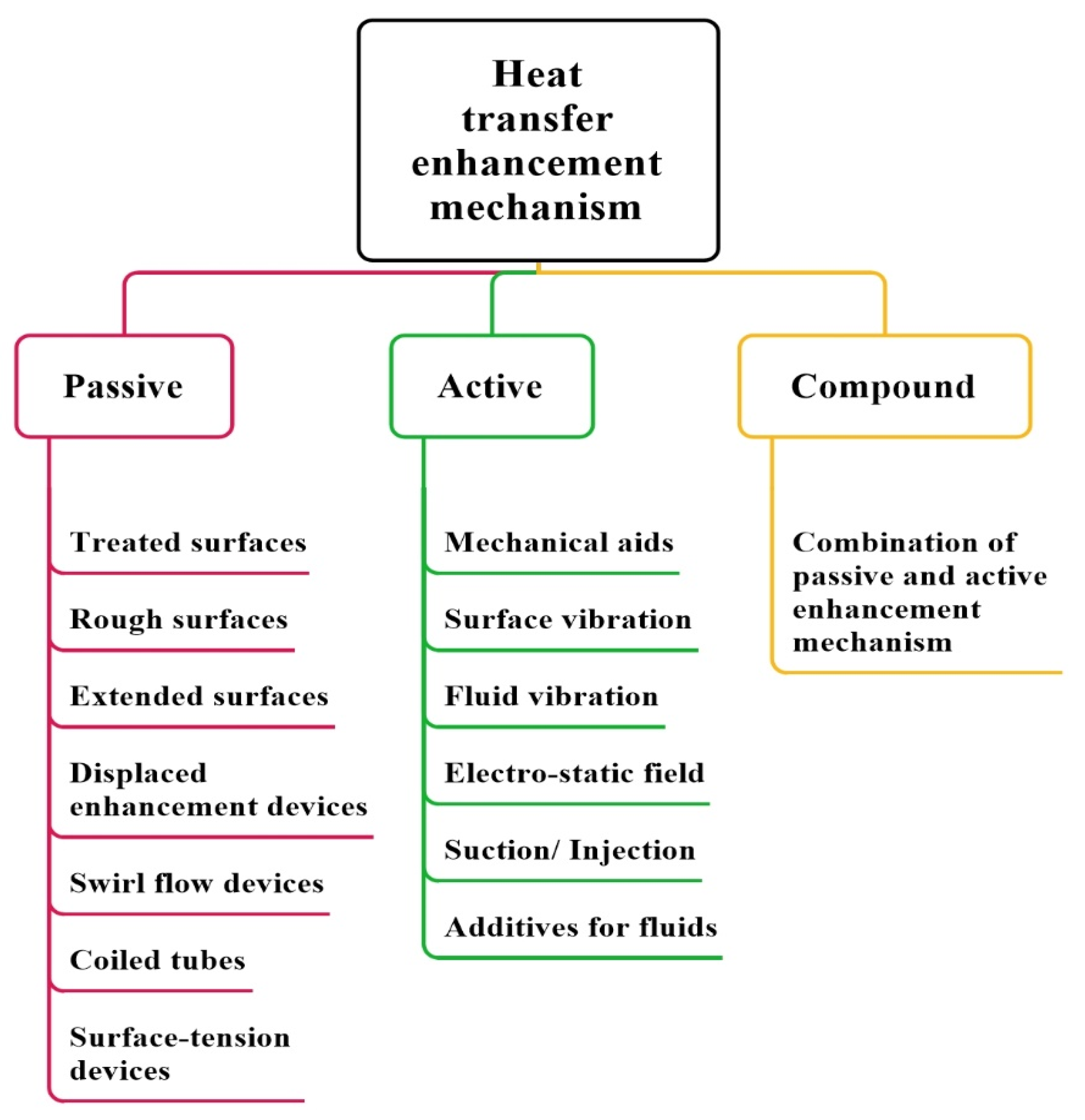
2. Heat Transfer Enhancement Mechanisms

Heat transfer enhancement mechanisms enhance the HTC within duly operating conditions for conducting experiments on boiling/condensation. If we are talking about the enhanced HTC, we must utilize several researchers’ heat transfer enhancement mechanisms.
The primary classifications of enhancement mechanisms are shown in Figure 4. All kinds of enhancement mechanisms for heat transfer can be broadly classified into two kinds: passive and active methods [52]. Passive enhancement mechanisms are mainly related to the tube surface as a treated surface, rough surface, and extended surface. Furthermore, the utilization of devices related to displaced enhancement, swirl flow, and surface tension to enhance surface quality favors improved HTC. However, active enhancement mechanisms are established based on forced convection heat transfer, where force sources are different in different mechanisms. For example, in mechanical aids, a kind of lever is utilized to enhance the heat transfer rate. Some vibration mechanisms, such as surface and fluid vibration, are also used to enhance the HTC. An electrostatic field is also utilized to enhance the fluid flow to enhance HTC. Different kinds of suction/injection techniques are also used to enhance the fluid flow, and some additives are used in fluids to enhance the fluid properties to obtain the enhanced HTC. The enhancement device, i.e., utilized in flow boiling, is a static mixer, and the swirl flow device is twisted tape and rough surfaces. These are produced by inserting helix, internal threads corrugate, and treated surfaces are produced by porous coating. Both passive and active enhancement mechanisms are insufficient to produce high enhancement individually. Therefore, a combination of both mechanisms is applied and known as the compound enhancement mechanism.
Cooke et al. [53] estimated bubble dynamics and heat transfer on micro-channel copper surfaces. The local thermal effect from high porosity and large average particle diameter inhibited heat transfer enhancement for high and moderate mass flows. Al-Zaidi et al. [54] examined how channel aspect ratio affects the flow patterns, heat transfer, and pressure drop of HFE-7100 flow boiling in copper multi-microchannel heat sinks. With 500 mm2 base areas and 0.46 mm hydraulic diameters, all three heat sinks exhibited the same channel bottom roughness. Horizontal multi-microchannel heat sinks boiled HFE-7100. Khaled et al. [55] made flexible fluidic thin films, presenting a passive fluidic thin film chilling method. Additionally, pressure drop widens the flexible micro-channel, making cooling more efficient (increased flow rate of coolant). Nanoparticles have better thermal conductivity than the working fluid and are the same size as base fluid molecules. Wang et al. sub-cooled a honeycomb plate to increase critical heat flow [56]. Water and porous material increased the process by 2.4. Sandeep et al. [57] found they should not cause heat exchanger abrasion, clogging, fouling, or pressure loss. Nanoparticles boost water, oil, and ethylene-thermal glycol conductivity, improving heat exchange equipment. Next, nanoparticle migration’s effect on heat transfer during nanofluid layer boiling over a vertical cylinder was explored theoretically. Studying alumina and titania nanoparticles, thermophoresis caused nanoparticles to concentrate near the warm wall. Heat transfer was enhanced. The net heat transfer rate was determined by lowering thermal conductivity and increasing wall temperature gradients. Siddique et al. [58] reviewed protrusions, porous media, big particle suspensions, nanofluids, phase-change devices, flexible seals and complex seals, extended surfaces, vortex generators, and composite materials with extraordinarily high thermal conductivity. The literature lists joint-fins, fin roots, fin networks, bi-convections, permeable, porous, and helical micro-fins. Micro-finned single-phase heat transfer reduced study inconsistencies. Other aspect ratio ranges, operating conditions, and working fluids are needed to confirm these findings.
Bergles [59] explained that different generations of heat transfer mechanisms are utilized in different industries to enhance HTC. The proper evolutionary generations are provided in Figure 5 for both inside-tube and outside-tube evaporation. The first generation for inside- and outside-tube evaporation starts the experiments with the smooth tube with different OD and ID with different types of pure or zeotropic refrigerants for evaluating the HTC. At the same time, the value of HTC is somehow also duly dependent on the quality of the surface, and to enhance the HTC, we have to enhance the surface inside or outside of the tube. Hence, second-generation 2D fins are utilized outside the tube, even when massive fins are used inside the tube for enhancing the HTC.
Further improvement in HTC is made in the third generation by applying the 3D fins or metallic coating on the outside-tube evaporation compared to micro-fins on the inside-tube evaporation. Micro-fins are a collection of fins with varying heights from 0.1 to 0.5 mm. The fins’ geometry can be longitudinal, helical, and two-dimensional (2D) or three-dimensional (3D). Primarily, the fin profile is based on their height-to-width ratio.
There are primary micro-fin heat transfer enhancement mechanisms provided by Thome [46], such as:
  • Extended surface area impact: The employment of micro-fins inside the smooth tube results in an extension in the surface area, and the ratio of these micro-fins might range anywhere from 1.2 to 1.8. The number of fins, their height, and the helix angle all significantly affect the outcome.
  • Enhanced convective heat transfer method: Micro-finned tubes function similarly in two-phase flow, as ribs are utilized in single-phase flow to increase the convective heat transfer across annular flow boiling.
  • Flow patterns impact: The micro-fins with helical geometry regularly convert stratified-wavy flow into an annular flow regime that is more efficient in heat transfer, which means all the wall perimeter inside the tube is wetter and more active than that of smooth tubes.
  • Nucleate boiling heat transfer method: The micro-fins help to activate the nucleation sites by slightly protecting the cavities.
  • Swirl flow effect: Enhanced micro-fins transmit swirl to the annular flow liquid film and hold back the inception of higher vapor qualities.

3. Recent Experiments on Micro-Fin Using Pure and Blends

Several experimental studies were done on the different kinds of pure and blended refrigerants from time to time. This review paper has just considered those involved from the three decades.
Schlager et al. [60] experimentally investigated the evaporation characteristics of R22, such as heat transfer inside a micro-fin tube at a horizontal position. Four kinds of tubes were used in the experiments, including one smooth and three micro-fin tubes. The outer diameters (ODs) were the same for each tube at 9.52   mm, but with different inner diameters (IDs). Experimental situations were: saturation temperature T s a t = 0 to 6   C; vapor quality x = 10 % to 20 % ; and mass flux G = 180 to 400 kg/m   2 s. Each micro-fin tube, they determined, contributed to a higher enhancement factor for heat transfer. There was a trade-off, though, because the higher the mass flux, the greater the pressure drop.
Schlager et al. [61] studied the evaporation and condensation characteristics of R22 inside a micro-fin tube at a horizontal position. ODs were the same for each tube, as 12.7   mm. Experimental situations were: saturation temperature T s a t = 0 to 5   C; vapor quality x = 10 % to 20 % ; and mass flux G = 75 to 300 kg/m   2 s. They came to the conclusion that each micro-fin tube offered a higher enhancement factor for heat transfer. With an increase in mass flux, there was, however, a consequence of a rising pressure drop.
Eckels et al. [62] experimentally investigated the evaporation heat transfer coefficient for horizontal flow boiling with the refrigerants R134a and R12 in a micro-finned tube with ID and OD of 8.72 mm and 9.52 mm, respectively. The experimental conditions were: T s a t = 5 to 15   C, G = 130 to 400 kg/m   2 s, and heat flux q = 5 to 15 kW/m   2 . Experimental results were given as a comparative study of both refrigerants, and it was found that R134a provides better HTC than R12 in the same experimental conditions.
Kaul et al. [2] investigated a horizontal micro-fin tube for better flow boiling heat transfer characteristics with alternative refrigerants. They used two micro-fin tubes as test sections with a length (L) of 3.34 m, and both were joint at the U-bend. The situations for the experiment were: x = 20 % , 40 % , and 60 % ; G = 314 364 kg/m   2 s; and q = 20 kW/m   2 . They concluded that R32/125 showed the best results as an alternative for R22, whereas R407c showed the lowest HTC due to the presence of less amount of R32 in it.
Kuo et al. [63] conducted experiments to gather information about HTC and Δ P in horizontal flow boiling with the refrigerants R22 and R407c in a micro-finned tube with ID and OD of 8.72 mm and 9.52 mm, respectively. The experimental conditions were: saturation pressure ( P s a t ) = 600   k P a , G = 100 to 300 kg/m   2 s, and q = 6 to 14 kW/m   2 . The overall results were provided in comparison of both refrigerants, and it was found that R22 has a good increase in HTC and pressure drop.
Nidegger et al. [64] conducted experiments in flow boiling to measure Δ P for R134a mixed with oil inside a micro-fin tube. The situations for the experiment were: ID = 11.90 mm; OD = 12.70 mm; L = 3.013 m; x = 10 99 % ; G = 100 , 200 and 300 kg/m   2 s; q = 5 to 10 kW/m   2 ; and oil concentration O i l C o n = 0 % to 5 % . They concluded that local HTC and Δ P achieved the maximum value at x = 75 % and G = 100 kg/m   2 s.
Cho. et al. [47] conducted experiments to investigate the pressure drop and HTC change under conditions A and B in the evaporation heat transfer for the refrigerants R22 and R407c in a micro-finned tube with two straight section U-bend. The conclusions were based on the percentage increase or decrease of pressure drop and HTC. They also explained the dimensionless HTC and enhancement factors for a better understanding of the results inside, as well as outside, of the U-bend tube.
Kabelac et al. [37] examined the boiling flow with ammonia as a refrigerant. They provided the experimental data for better understanding of the use of ammonia-based refrigerant mixed with polyglycol oil in two different test tubes: the first was a smooth aluminum tube with ID 10 mm and OD 12 mm, and the second one was a spirally fluted micro-finned tube with maximum ID 11.13 mm, along with tube length of 0.45 m. They concluded that mass flux influenced the results highly because of the mass flow oscillations.
Yu et al. [24] experimentally investigated the heat transfer and flow patterns for R134a in the test section as two horizontal tubes; one was a smooth tube, and another was a micro-finned tube. The test sections’ lengths and diameters were 1.5 m and 12.7 mm OD, respectively. They submitted the comparison between HTC for smooth tubes and HTC for the micro-finned tube. Furthermore, as a result, the HTC could be increased by 200 % at minimum mass flux and maximum quality for the micro-finned tube surface.
Kim et al. [65] evaluated the heat transfer characteristics of R410a in smooth and micro-fin tubes to obtain an alternative to refrigerant R22. The experimental result always showed that the local HTC increased with an increase in mass and heat flux.
Passos et al. [38] studied convective boiling with four test tubes—two smooth tubes and two micro-fin tubes—for R407c. The outer diameters for the tubes were 7 mm and 12.7 mm, whereas the inner diameters differed for each test section. The occurrence of dry out held at the different quality for smooth and micro-finned tubes as 0.70 and 0.78 , respectively.
Filho et al. [40] studied convective boiling with six test sections as three smooth tubes and three micro-fin tubes for R134a. The outer diameters for tubes were 7 mm, 7.93 mm, and 9.52 mm, whereas the inner diameters differed for each test section. They provided information about the frictional effect on flow patterns with the help of Martinelli’s correlations. They proposed a correlation for the experimental data set and provided the conclusions for grooved and smooth tubes. The flow patterns studied by them were mainly annular and misty flow.
Greco et al. [39] looked into the evaporation of refrigerant (R22 and R507) inside the smooth tube. They experimentally explained the HTC improvement and lower pressure drop conditions. They also compared the experimental data with calculated data from correlations. The comparative study between R22 and R507 based on HTC and pressure drop were also explained. They calculated the results based on considering local HTC and pressure drop as a quality function using correlations from literature.
Koyama et al. [22] investigated the void fraction for smooth and grooved tubes with refrigerant R134a in the horizontal test condition. The experiments were conducted to investigate the void fraction for the smooth and grooved tubes. They concluded that as the pressure decreased, the void fraction increased. The impact of mass flux in the micro-finned tube was more than in the smooth tube.
The performance features of R134a during evaporation heat transfer were investigated by Wongsa-ngam et al. [66] in the smooth and micro-fin tube at a high mass flux-region. The test results for both smooth and micro-fin tubes showed an increase in average HTC, with increases in average x , G , and T s a t , whereas Δ P slightly went down with the increase of T s a t .
Kim et al. [67] experimentally investigated the HTC in smooth and micro-finned tubes with R22 and R410a refrigerants for evaporating heat transfer. They took one smooth and seven micro-finned tubes with different fin profiles. They concluded the results with a comparison of Kandlikar’s correlation. They presented the comparative results for smooth and micro-finned tubes, with the smooth tube having a lower HTC than the micro-finned tube.
Wellsandt et al. [48] experimentally investigated the HTC and pressure drop in herringbone micro-finned tubes with R134a refrigerants for evaporating heat transfer. They concluded that the calculated HTC improved at high mass flux and high vapor quality ranged 0.5 to 0.6, whereas there was no influence of heat flux. The experimentally observed pressure drop was compared with the calculated pressure drop from correlations provided by Domanski and Kedzierski. The pressure drop was also increased with the same mass flux.
Wellsandt et al. [68] experimentally investigated the HTC and pressure drop in herringbone micro-finned tubes with R407c and R410a refrigerants for evaporating heat transfer. After comparing it with their previous studies, they concluded that the HTC for R-134a was higher than R410a and R407c. The dependency of the HTC on heat flux depended on the vapor quality, whether low or high.
Filho et al. [69] experimentally investigated the HTC and pressure drop in smooth, herringbone micro-finned, and standard micro-finned copper tubes with R134a refrigerant for convective boiling. They concluded that HTC for the smooth tube was less than the micro-finned tubes, but the increase in pressure drop may not vary highly. For obtaining better performance comparability between the micro-finned geometries, an enhancement factor was introduced.
Gao et al. [27] conducted experiments to investigate the flow boiling heat transfer characteristics of pure CO   2 and CO   2 mixed with oil inside horizontal micro-fin tube. It was found that pure CO   2 provided much better HTC than CO   2 mixed with oil due to the oil suppression of a film. Further, dry-out quality was found not to majorly influence an increase in mass velocity in the micro-fin tube.
Targanski et al. [70] investigated the evaporation heat transfer for R407c pure and mixed with oil inside the micro-fin tube. Experimental situations were: T s a t = 0   ° C, L = 2 m, OD = 10 mm, G = 250 to 500 kg/m   2 s, and x = 0 % to 70 % . They found that the pure R407c showed better HTC than the oil-mixed R407c with the same working conditions. Both HTC and Δ P were found to be higher for the enhanced tube.
Cho et al. [71] investigated the characteristics of flow boiling heat transfer of pure CO   2 and CO   2 mixed with oil inside horizontal smooth and micro-fin tubes experimentally. They concluded that the micro-fin tube showed higher evaporation HTC than smooth tubes for the same test conditions, and it was found to   be   150 to 200 % more for the micro-fin tube. The better heat transfer performance was achieved at a highly wet portion in annular flow within the micro-fin tube.
Zhang et al. [72] experimentally studied HTC for horizontal internally grooved tubes with the refrigerants R417a and R22. They concluded that the evaporation of HTC increased with mass flux, as HTC mostly depends on mass flux in convective boiling. The HTC also increased with heat flux, as HTC mostly depends on heat flux in nucleate boiling. HTC increased with an increase in vapor quality at the start of the boiling, but with a further increase in vapor quality, HTC went down.
Cui et al. [30] studied the flow characteristics of R134a inside a micro-fin tube, such as flow pattern and Δ P , experimentally. They concluded that the different flow regimes were found at different mass flux, but mostly at G = 100 stratified way flow was found. Additionally, the Δ P for stratified flow regimes and annular flow regimes was found to be high and efficient.
Hu et al. [73] studied the flow boiling heat transfer characteristics of R410a mixed with oil inside a micro-fin tube. The experiment results showed that the HTC increased with increasing vapor quality at low oil concentration, but decreased as per the increase in oil concentration, with a further increase in vapor quality.
Spindler et al. [74] studied flow BHT experimentally inside a micro-fin tube at low mass and heat flux. The working refrigerants were R134a and R404a. In the micro-fin tube pattern, transitions at low G and x , compared to smooth tube HTC for R404a, were 1.5 times lower than R134a.
Ding et al. [75] investigated the flow boiling characteristics in two-phase, such as the frictional pressure drop of the inside micro-fin tube with refrigerant R410a mixed with oil. The pressure drop of pure R410a increased at the start as the vapor quality increased, but a further increase in vapor quality caused a decrease in pressure drop.
Ono et al. [76] experimentally investigated the flow boiling heat transfer and flow characteristics of CO   2 mixed with oil inside horizontal smooth as a tube made of stainless steel and a micro-fin tube made of copper. They found most of the flow patterns in slug and wavy flow regimes for smooth tubes, whereas annular flow regimes were for the micro-fin tube. Moreover, the HTC for the smooth tube was lesser than these of the micro-fin tube.
Hatamipour et al. [31] studied the flow boiling of R134a horizontal smooth and the micro-fin tube to know the flow regimes and heat transfer during it. They found three kinds of flow patterns in the visual study: stratified wavy flow, second wavy annular flow, and third annular flow. The annular flow regime was found at a high value of vapor quality, whereas the stratified-wavy flow was found at a low value of vapor quality. They found HTC for micro-fin tubes 6 % higher than these for the smooth tube at the same mass flow conditions.
Dang et al. [77] studied the flow boiling heat transfer characteristics of CO2 inside the micro-fin tube. They concluded that HTC had been affected by heat flux in smooth and micro-fin tubes, whereas the mass flux did not support HTC enhancement of all fuel. The dry-out was found at maximum vapor quality within the micro-fin tube and was dependent on the heat flux and mass flux values. They also suggested applying a high heat flux with low mass flux to get better HTC and appropriate low-pressure drop.
Zang et al. [78] experimentally studied the flow boiling characteristics of R417a and R22 in horizontal smooth, as well as in micro-fin tubes. They found higher HTC for R417a and R22 at high vapor quality inside the micro-fin tube. Comparatively, heat transfer enhancement factor for R22 was higher than those for R417a.
Rollmann et al. [79] investigated the flow boiling characteristics of R407c inside the horizontal micro-fin tube. They found that HTC could be high at a low saturation temperature. Further, HTC increased with an increase in vapor quality. The pressure drop was found to be decreased, with decreasing vapor quality, as well as heat flux.
Padovan et al. [80] investigated the flow boiling characteristics for R134a and R410a inside a horizontal micro-fin tube. They found that the HTC for R134a had achieved the highest values at the high value of mass flux. The dry-out quality was studied with high values of vapor quality and calculated with Mori correlations. Moreover, after a certain value of vapor quality, HTC improved with high heat flux, as HTC is mostly dependent on HTC.
Behabadi et al. [81] conducted experiments with R134a to investigate the evaporation heat transfer in a micro-fin tube with various inclinations of the tube. They found peaks in HTC at + 30   from the horizontal plane with high vapor quality and at a position of + 90   with low vapor quality.
Filho et al. [82] investigated the flow boiling characteristics for R134a inside a horizontal micro-fin tube. They found wavy-annular flow regimes for the micro-fin tube at working conditions: T   s a t =   5   ° C, G   = 300 kg/m   2 s, and x = 10%. However, it impacted the HTC of the micro-fin tube with the same experimental criteria.
Baba et al. [83] investigated the flow boiling characteristics, such as pressure drop and heat transfer, for R1234ze(E) and R32 in the horizontal micro-fin tube. They found that HTC increased as the vapor quality increased in all experimental situations for both refrigerants. Additionally, HTC for R32 is higher than those for R1234ze(E).
Konduo et al. [84] experimented with investigating the flow boiling of R32 and R1234ze(E) in horizontal micro-fin tubes. They found that the HTC of R32 was approximately 100 % higher than those of R1234ze(E) at the low value of vapor qualities.
Kim et al. [35] studied the characteristics, such as HTC and ΔP of CO2, inside plain and enhanced tube micro-fin. As a result, they found out that the HTC for the micro-finned tube was more influenced by increasing the value of vapor quality and mass flux compared to the smooth tube, however, no major effect of oil concentration on it.
The boiling and condensation properties of the refrigerant R134a were investigated by Colombo et al. [34] using a 9.52 mm micro-fin tube. According to them, the HTC of evaporation was improved with the low value of mass flux, while at the same time, HTC was highly dependent on heat flux. They demonstrated, via the flow map, where the change has taken away intermittent flow to annular flow to take place for a constant mass flux within the low-range vapor quality. Further, the flow regime transitions were moved to the high range of vapor quality with the application of the micro-fin tube.
The flow boiling heat transfer features of R1234yf pure, as well as oil-mixed refrigerants, were examined by Han et al. [85] under the following test conditions: T s a t = 5 to 15   ; G = 100, 200 and 400 kg/m2s; q = 4, 8, and 12 kW/m2; and Oil c o n = 0%, 1.5%, 3%, and 5%. They researched inside a micro-finned tube with a 7 mm OD. They discovered that the local HTC for pure and oil-mixed R1234yf had grown, in addition to a low-to-high range of vapor quality maintained when operating at higher rates of mass velocity. Moreover, at a low oil content, heat transfer was excellent.
Mancin et al. [86] inspected flow boiling heat transfer experimentally, including various mass fluxes from 190–755 kg/m2s and variable heat fluxes, for refrigerant R134a flowing within a 3.4 mm ID micro-finned tube. They determined the high value of HTC at a high heat flux value with low vapor quality. However, heat flux was not influencing the HTC at the condition of high vapor quality.
Wu et al. [87] considered the flow boiling heat transfer for inorganic refrigerant CO2 flowing within the micro-finned with varied mass flux from 106–600 kg/m2s at changing T s a t from 1 to 15   for experiments. They discovered that when the mass or heat flux increased, the pressure drop increased at low saturation temperatures. The value of local HTC rose within the low to medium vapor quality range. However, at a low level of vapor quality, the value of HTC dropped dramatically. Furthermore, with a high value of mass flux, HTC enhancement may be optimal.
A comparative investigation of the flow boiling heat transfer with various refrigerants flowing within plain and micro-fin tubes has been given by Jiang et al. [88]. They found that the average HTC of R-134a was 110.9% higher than R-22 when measured within a smooth tube. At the same time, the average HTC of R-407c was 78% more than R-22 inside a smooth tube. Further, the average HTC of R-410a was 125.2% more than R22 inside the smooth tube.
Diani et al. [89] prepared a 3 mm horizontally oriented micro-fin tube for testing the flow boiling heat transfer at T s a t = 30 , having vapor quality ranging from 10% to 99%, the mass flow of 375–940 kg/m2s, and 10–50 kW/m2 heat flux with refrigerant R1234ze(E). They discovered that the HTC of micro-finned tubes was higher within the low vapor quality range at the high heat flux value than those of smooth tubes. They also identified that the value of HTC was low at a low value of vapor quality and increased with increasing vapor quality. In further experiments, they utilized different refrigerants, such as R134a [42] and R513a [90], and they obtained the vital importance of micro-fins in improving HTC.
Longo et al. [91] explored experimentally flow boiling characteristics inside the micro-fin tube for R245fa at T s a t = 30 , G = 100 to 300 kg/m2s, q = 30 to 60 kW/m2, and x = 15% to 95%. They established that the value of HTC got affected mainly during the transition of regimes. They also conducted experiments to obtain a comparative analysis to distinguish between the flow boiling of R1234yf and R1234ze(E) [24].
Han et al. [92] tested flow boiling heat transfer features for R161 mixed with varying oil concentrations from 0–5% flowing inside a 7 mm micro fin tube. Experimental circumstances were as G = 100 to 250 kg/m2s and q = 11.76 to 52.94 kW/m2. They discovered that the quality of the vapor, in conjunction with the amount of oil present, significantly impacted the value of HTC. At the same time, HTC was negatively impacted by the lowest possible level of vapor quality. Additionally, when the mass flow increased, the value of HTC decreased.
Jige et al. [93] developed a 3 mm horizontal micro-fin tube to examine heat transfer attributes of R32 experimentally at a fixed saturation temperature of 15 , with G = 50–500 kg/m2s, and q = 5–20 kW/m2. Consequently, they concluded that there was an increase in the value of HTC, despite the poor quality of the vapor present, in association with a hike in heat and mass flux. However, when the vapor quality was good, the impact of heat and mass flux was not nearly as significant on HTC. The slug flow was changed from slug to wavy flow with a low value of mass flux. Additionally, the flow changed to an annular flow as the mass flux rose.
Celen et al. [94] evaluated the flow boiling heat transfer characteristics for R134a flowing in both plain and micro-fin tubes. They postulated that with increasing saturation temperature, the value of the average HTC increased. Moreover, the HTC of micro-fin tubes was 1.9 times that of smooth tubes.
Righetti et al. [95] performed experiments to enhance the properties of boiling heat transfer of R1233zd(E) flowing within a micro-finned tube having an internal diameter of 4.3 mm. They demonstrated that the value of HTC was diminished, primarily due to the phase change procedure. In addition, HTC rose with all different mass flux values, despite having a very modest heat flux of 30 kW/m2.
Sun et al. [16] evaluated flow boiling heat transfer properties within smooth, micro-fin, and 3D improved tubes for R410a. They postulated that HTC grew with a higher value of mass flux due to the intense shape action. Hence, the HTC value for this tube was always the greatest.
Lin et al. [96] inspected the two-phase evaporation heat transfer properties under the testing circumstances as T s a t = 6 and G = 130 to 550 kg/m2s inside a micro-finned tube for R22. They concluded that the micro-finned tube outperformed the plain tube in obtaining a high HTC value under low mass flux circumstances.
Jige et al. [97] considered R32 circulating within a micro-fin tube for performing the experiments on flow boiling heat transfer with testing circumstances as T s a t = 15 ; G = 50 to 400 kg/m2s; q = 2.5, 5, 10, and 20 kW/m2; and x = 10% to 90%. They discovered that the value of HTC rose with the rising value of heat and mass flux, even while the vapor quality had kept at its lowest possible level. Nevertheless, the value of HTC did not grow nearly as much as the value of heat or mass flux when the vapor quality was at its highest possible value.
Refrigerant R245fa flowing inside a micro-finned tube was considered for experiments by Liu et al. [98] for getting enhanced flow boiling heat transfer characteristics at testing conditions as the constant saturation pressure as   ( P s a t ) = 0.2 MPa, G = 50 to 240 kg/m2s, and q = 5.6 to 14.87 kW/m2. They inferred that the value of HTC for the micro-finned tube was better than that of the plain tube. Further, the significance of the high mass flux value was less than the value of HTC for the micro-finned tube.
Further, Wang et al. [99] mixed R424fa with R141b to obtain better performance parameters of flow boiling inside an 8.72 mm micro-fin tube at varying mass flux from 203.19 to 306.64 kg/m2s with heat flux ranging from 7–15 kW/m2. They recognized that the increasing mass percentage of R245fa influenced HTC very highly. In addition, HTC decreased when saturation temperature increased, and it increased along with the value of mass flux.
Moon et al. [100] investigated the features of R600a within micro-finned tubes. The latest studies on flow boiling heat transfer compared it with smooth tubes using home refrigerator operating circumstances. They found that R600a inside micro-fin had superior properties to smooth tubes. The comparison was made based on factors such as enhancement and penalty. The micro-fin tube performed better and gave a higher enhancement factor in low mass flux circumstances. They also provided a robust correlation for a more accurate analysis of HTC.
Also, the relatively recent studies by Wu et al. [101] talked about flow boiling of a combination of two refrigerants, R1234ze(E) and R152a, by mass as 0.4 and 0.6, correspondingly. This information was presented in the form of a ratio. During the boiling process, the mixture showed signs of dry-out occurrence.
The impact of micro-fin geometry is also a significant factor because the increasing ratio of cross-section area to the volume of micro-fin increases the HTC of the tube. Figure 6a,b depict the 2D and 3D perspectives of the cross-sectional view of the micro-fin tube, respectively. Figure 7a–c visually represent the micro-fin tube geometrical parameters, including ID, OD, tube thickness, apex angle, fin height, and helix angle. These geometrical parameters highly influence the cross-sectional area. Therefore, we should know about it and choose the right or optimal geometries for the experiments so that we can get highly enhanced HTC compared to a smooth tube.
The summary of the previous investigations on two-phase and flow boiling heat transfer of pure and mixed refrigerants in micro-fin tubes is provided in Table 2, and the specifications of micro-fin tube geometry for different experimental studies of pure and mixed refrigerants are also given in Table 3.
In Figure 8a, a comparison between the refrigerants R134a and R513a has been done based on the effect of heat flux on HTC by obtaining the data from the different authors [41,42,48,80,82,86,94], research at vapor quality range from 0 to 1, and also values of heat flux are taken as 10 , 20 , and 40 kW/m   2 . From Figure 8a, we can observe that R513a shows a better HTC for the same working heat flux than R134a. R513a is the advanced version of R134a. The high HTC is obtained at 10 kW/m   2 and 40 kW/m   2 heat flux, but we should also consider the mass flux and the geometries of the tube and micro-fins before concluding. In Figure 8b, we can see that the results were those because of high mass flux G = 300 kg/m   2 s. Therefore, we can understand the HTC dependency on heat and mass flux, i.e., both influence the HTC highly for the same working conditions of the tube and micro-fin geometries. The experimental conditions taken by different authors are provided in Table 4.
In Figure 9a, a comparison among refrigerants R407c, R410a, and R32 has been made based on the effect of heat flux on HTC by obtaining the data from the different authors [38,63,67,68,84,93], research at vapor quality range from 0 to 1, and also values of heat flux are taken as 10 , 20 , and 40 kW/m   2 . From Figure 9a, we can observe that HTC increases as the value of heat flux increases, but somehow, at high heat flux, HTC shows low values also; it is because of the influence of mass flux at low mass flux that HTC can be low, no matter how high the heat flux. It may also be due to the tube geometry selected by the authors to show the different values of HTC at the same heat flux. It is also caused by the geometry of the micro-fin inside the tube. They are triangular or rectangular or trapezoidal. The fin helix angle may also influence it. However, overall, HTC at 10 kW/m   2 heat flux showed the best results from the authors. For R407c, at 20 kW/m   2 heat flux, HTC is also high after the vapor quality is beyond 0.5 in comparison to 40 kW/m   2 heat flux. Nevertheless, in R410a and R32, this is entirely different. At 10 kW/m   2 heat flux, we got high HTC. In Figure 9b, a comparison among refrigerants R407c, R410a, and R32 has been done based on the effect of mass flux on HTC by obtaining the data from the different authors [38,63,67,68,84,93], research at vapor quality range from 0 to 1, and also values of mass flux are taken as 200 and 300 kg/m   2 s. It is essential to go through the mass flux effect simultaneously if talking about the heat flux effect because both significantly influence the HTC. We cannot ignore the tube and micro-fin geometry utilized to enhance the HTC at low heat and mass flux. We can see that the high HTC can be obtained at G =   300 kg/m   2 s rather than G =   200 kg/m   2 s because of better-enhanced tube geometries and micro-fins. Again, the HTC for R32 shows better results at the same working mass flux than R407c and R410a. The experimental conditions taken by different authors are provided in Table 5.

4. Flow Boiling Models

For a researcher to make more accurate predictions rather than relying on experimental findings, understanding the correlations between the variables is of the utmost importance. The flow boiling models are the supported equations that offer the correlations among the factors that impact the flow boiling heat transfer. Of the many correlations found up to this point, we have separated them into the following categories.

4.1. Generalized Flow Boiling Models

The generalized flow boiling models are applicable for refrigerants to get the calculated values of HTC to compare with the experimental HTC values. The main generalized flow boiling models are provided below in Table 6.

4.2. Flow Boiling Models for Pure Refrigerants

There are different correlations that exist for calculating HTC for pure refrigerants. Some of these are listed below in Table 7.

4.3. Flow Boiling Models for Blended Refrigerants

Different correlations also exist for calculating HTC for blended refrigerants. Some of these are listed below in Table 8.
Figure 10, Figure 11, Figure 12 and Figure 13 [120] show the residuals of the Lin et al. [120] model versus x for 16 different refrigerants. The residuals are typically within 30% and do not show any subset of variables depending on the refrigerant or fluid. For R1234ze(Z), R1233zd(E), R1224yd(Z), R161, and R450A, where the quantities of data are rather minimal, the residual populations are somewhat unbalanced (i.e., less than 150 data points from 1 or 2 sources) since the statistics from 13 various sources seem to be subject to various errors (10% to 30%) and are assessed using various techniques, such as heating by any fluid or electric heating. To understand this, if we consider R134a here, then the residuals for R134a are considerably scattered, which is to be desired. Nevertheless, the MAE is 15.9%, and the model continues to accurately forecast 85% of the R134a data. Figure 11 shows that the validity of the model is mostly unaffected by the refrigerant of choice. Thus, the model can be expanded to include various refrigerants.

5. Overview

As an improved surface for two-phase flow heat transfer, advanced micro-fin tubes are now extensively applied in HVAC (R), heat pumps, and chillers as a mature technology. Refrigeration and air conditioning manufacturers customize these kinds of heat exchangers with enhanced surfaces to significantly reduce the refrigerant-filling capacity and the flow rate of machinery. For this reason, micro-finned tubes have increased in popularity since they may significantly improve heat transfer (70–190%) compared with identical plain tubes under similar working circumstances, while increasing pressure drop slightly (15–85%). In addition, the placement of fins around the tube’s periphery expedites the transition to an annular regime, which has a greater HTC than during stratified regimes. It is also delayed in terms of vapor quality regarding the dry-out phenomenon. While there are some inherent technical difficulties with the manufacturing process of micro-fin tubes, these may be overcome by optimizing the fin height and tube diameter and using compelling, low-cost manufacturing challenges. The current research ideas appear to be directed in these regions to popularize this modern technology. It was noticed that a significant portion of the research is devoted to the development of low-cost, high-efficient micro-fin tubes. Many synthesized designs and models were identified, developed, and tested to manufacture enhanced micro-finned tubes. Designing micro-finned tubes with smaller diameters and more fins for improving heat transfer is essential in developing new micro-finned tube designs. It is noticed that the maximum HTCs at high mean vapor quality are shown during the implementation of lower heat flux, revealing that there may be some localized hot spots on the inner surface of the tubes, resulting in a deterioration of the phase change process when heat flux increases rapidly. The following factors make micro-fin tubes necessary, as well as convenient:
  • Micro-fin tubes improve the heat-exchanging surface area.
  • Micro-fin tubes induce turbulence to the liquid phase, hence improving the HTC.
  • Micro-fin tubes improve HTC by developing the effect of surface tension on the liquid phase.
  • Many types of heat transfer equipment, including heat pumps, RAC systems, HVAC systems, and chillers, employ micro-fin tubes to improve HTC in single- and two-phase modes.
  • For future reference, long-term miniaturized cooling systems should be built to address the energy recovery issue, i.e., removing and reusing vast amounts of heat in storage systems.

6. Concluding Remarks

Micro-fin tubes have emerged as a promising suitable alternative for producing advanced enhanced modes of heat transfer mechanisms. The significant characteristics of this tube are that it may increase the heat transfer area and fluid disturbance, modify the flow speed and direction due to centrifugal force, and, consequently, enhance the HTC. This topic will continue to get interesting as the emphasis switches to enhancing heat transfer, decreasing pressure drop, enhancing mean vapor quality, and incorporating these processes into practical devices. We will witness a dramatic transformation that will likely result in considerable equipment size reductions for some conventional heat transfer systems and introduce new products employing micro-scale technology.
Flow boiling in micro-fin tubes is gaining momentum since its constraints of establishing robust performance are resolved with a thorough understanding of the underlying mechanisms. Developing cheap and low-cost technologies for conducting flow boiling mechanisms under steady-state conditions will be a key research focus. The augmentation of the flow boiling HTC using innovative approaches will keep attracting interest. Incorporating most existing enhancement techniques in miniature heat exchanger passageways will be the highest priority subject of investigation. Another investigation area is using nanocoatings on tube walls to reduce the wall superheat temperature at incipience and increase critical heat flux.
According to the above research, since micro-fin tubes using mixed, low ozone layer depletion (ODP) and global warming potential (GWP) refrigerants were extensively investigated, numerous experimental and theoretical investigations were carried out, and many flow boiling heat transfer models were proposed in published papers to evaluate HTC. Interestingly, based on the survey results mentioned above, it is determined that micro-fin tubes provided a more excellent value of HTC, ranging from 90% to 190%, than smooth tubes under the same operating circumstances. Furthermore, micro-fin tubes had a higher heat transfer enhancement factor of 1.5 to 2.5 than smooth tubes with similar tube geometries.

7. Challenges and Possible Future Directions

The present review article analyzes widely reported experimental explorations on the flow boiling over horizontal micro-fin tubes and discusses variations in research findings. Further, there are some challenges and possible future directions to be performed, such as:
  • Rather than measuring mean data or utilizing electrical heating, future work should concentrate more on assessing local values by employing warm water heating.
  • Vapor quality studies should be performed up to 1.0.
  • In addition, further work has to be done to include reliable numerical flow models for use with flow boiling in micro-finned tubes.
  • Growth in the flow boiling heat transfer performance must be essential before this method can be utilized in real devices.
  • Also, all of us are trying to learn about nanocoating and nano-refrigerant, which seems to offer even more exciting potential for researchers working on heat transfer, along with fluid flow, in upcoming years.
  • More study is needed to determine how a nanofluid promotes heat transfer, largely via these methods. Researchers should also take care to quantify the degrees to which flexible/flexible-complex seals increase heat transfer, flow, and heat transfer in a convective medium in the right sequence. This describes heat transfer-enhancing active mechanical technologies.

Author Contributions

Conceptualization, N.K.V., S.D. and D.C.D.; methodology, N.K.V.; formal analysis, N.K.V.; investigation, N.K.V.; resources, S.P. and A.K.D.; data curation, N.K.V.; writing—original draft preparation, N.K.V. and S.D.; writing—review and editing, S.P., A.K.D., S.S.G. and B.B.S.; supervision, S.P., A.K.D., S.S.G. and B.B.S.; project administration, S.P., A.K.D., S.S.G. and B.B.S.; All authors have read and agreed to the published version of the manuscript.

Funding

This research received no external funding.

Institutional Review Board Statement

Not Applicable.

Informed Consent Statement

Not Applicable.

Data Availability Statement

Not Applicable.

Conflicts of Interest

The authors declare no conflict of interest.

Nomenclature

A c Cross-sectional flow area inside tube, [m2]
A w Cross-sectional tube wall area per fin, [m2/fin]
B d Bond Number
B o Boiling Number
C o Confinement Number
CO 2 Carbon dioxide
C p , l Liquid specific heat, [kJ/kg.K]
C v Convection Number
D b Departure bubble diameter, [m]
D h Hydraulic diameter, [m]
d r Root Diameter, [m]
E R B Convection enhancement factor
E m f Micro-fin enhancement factor
F Two-phase heat transfer multiplier
f Friction factor
F c Mixture correction factor
F r Froude Number
G Mass flux, [kg/m2s]
G a Galileo number
GWPGlobal warming potential
H Fin height, [mm]
h Heat transfer coefficient, [Wm−2 °C−1]
HCFCsHydro-chlorofluorocarbons
h lg Latent heat of evaporation, [kJ/kg]
HTCHeat transfer coefficient, [Wm−2 °C−1]
IDInner diameter, [m]
k Thermal conductivity, [Wm−1 °C−1]
LLength of the tube, [m]
M Molecular weight, [kg/kmol]
n Number of fins
NH 3 Ammonia
N u Nusselt Number
ODOuter diameter, [m]
ODPOzone depletion potential
p Perimeter, [m]
P Pressure, [kPa]
Pr Prandtl number
q Heat flux, [kW/m2]
RACRefrigeration and air conditioning
Re Reynolds number
S Boiling suppression factor
S p Perimeter of fin, [m]
S u Suratman number
T Temperature, [°C]
T b Bubble point temperature of mixture, [°C]
T d Dew point temperature of mixture, [°C]
T s Saturated state temperature of mixture, [°C]
W e Weber Number
x Vapor Quality
X Lockhart–Martinelli parameter
x q Thermodynamic mass quality
Greek Letters
β Helix angle, [°]
δ Liquid film thickness, [m]
ϕ 2 Two-phase frictional multiplier gradients and differences
γ Apex angle, [°]
μ Dynamic viscosity, [Pa.s]
θ d r y Dry angle, [radian]
ρ Density, [kg/m3]
σ Surface tension, [N/m]
Subscripts
C Critical condition
cCross-sectional
c b Convective boiling
c o n Concentration
e v p Evaporation
g Vapor
l Liquid
L V Least volatile component
m i c r o Micro-fin tube
M V More volatile component
n b Nucleate Boiling
R Reduced
r e f Refrigerant
s a t Saturation
s m o o t h Smooth tube
S P Single-Phase
T P Two-Phase
t t Turbulent-Turbulent
v v Laminar-Laminar
w wall

References

  1. Manzer, L.E. The CEC-Ozone Issue: Progress on the Development of Alternatives to CFCs. Science 1990, 249, 31–35. [Google Scholar] [CrossRef] [PubMed]
  2. Kaul, M.P.; Kedzierski, M.A.; Didion, D.A. Horizontal flow boiling of alternative refrigerants within a fluid heated micro-fin tube. ASHRAE Trans. 1996, 102, 167–173. [Google Scholar]
  3. Wuebbles, D.J.; Calm, J.M. An Environmental Rationale for Retention of Endangered Chemicals. Science 1997, 278, 1090–1091. [Google Scholar] [CrossRef]
  4. Righetti, G.; Longo, G.A.; Zilio, C.; Mancin, S. Flow boiling of environmentally friendly refrigerants inside a compact enhanced tube. Int. J. Refrig. 2019, 104, 344–355. [Google Scholar] [CrossRef]
  5. Longo, G.A.; Mancin, S.; Righetti, G.; Zilio, C. R1234yf and R1234ze(E) as environmentally friendly replacements of R134a: Assessing flow boiling on an experimental basis. Int. J. Refrig. 2019, 104, 336–343. [Google Scholar] [CrossRef]
  6. Nujukambari, A.Y.; Bahman, A.S.; Hærvig, J.; Sørensen, H. A Review: New Designs of Heat Sinks for Flow Boiling Cooling. In Proceedings of the 2019 25th International Workshop on Thermal Investigations of ICs and Systems (THERMINIC), Lecco, Italy, 25–27 September 2019; IEEE: Piscatvie, NJ, USA, 2019; pp. 1–6. [Google Scholar] [CrossRef]
  7. McLinden1, M.O.; Seeton, C.J.; Pearson, A. New refrigerants and system configurations for vapor-compression refrigeration. Science 2020, 370, 791–796. [Google Scholar] [CrossRef]
  8. Yang, C.; Seo, S.; Takata, T.K.; Miyazaki, T. The life cycle climate performance evaluation of low-GWP refrigerants for domestic heat pumps. Int. J. Refrig. 2021, 121, 33–42. [Google Scholar] [CrossRef]
  9. Wu, D.; Hu, B.; Wang, R.Z. Vapor compression heat pumps with pure Low-GWP refrigerants. Renew. Sustain. Energy Rev. 2021, 138, 110571. [Google Scholar] [CrossRef]
  10. Montzka, S.A.; Dutton, G.S.; Yu, P.; Ray, E.; Robert, W.; Daniel, J.S.; Kuijpers, L.; Hall, B.D.; Mondeel, D.; Siso, C.; et al. An unexpected and persistent increase in global emissions of ozone-depleting CFC-11. Nature 2018, 557, 413–417. [Google Scholar] [CrossRef] [Green Version]
  11. Mendoza-Miranda, J.M.; Salazar-Hern’andez, C.; Carrera-Cerritos, R.; Ram’ırez-Minguela, J.J.; Salazar-Hern´andez, M.; Navarro-Esbr´, J.; Mota-Babiloni, A. Variable speed liquid chiller drop-in modeling for predicting energy performance of R1234yf as low-GWP refrigerant. Int. J. Refrig. 2018, 93, 144–158. [Google Scholar] [CrossRef]
  12. Dione, K.R.; Louahlia, H.; Marion, M.; Berçaits, J.L. Evaporation heat transfer and pressure drop for geothermal heat pumps working with refrigerants R134a and R407C. Int. Commun. Heat Mass Transf. 2018, 93, 1–10. [Google Scholar] [CrossRef]
  13. Rigby, M.; Montzka, S.A.; Dutton, G.S.; Yu, P.; Ray, E.; Robert, W.; Daniel, J.S.; Kuijpers, L.; Hall, B.D.; Mondeel, D.; et al. Increase in CFC-11 emissions from eastern China based on atmospheric observations. Nature 2018, 569, 546–549. [Google Scholar] [CrossRef] [PubMed] [Green Version]
  14. Henne, S.; Fang, X.; Prinn, R.G.; Manning, A.J.; Krummel, P.B.; Liang, Q. A decline in emissions of CFC-11 and related chemicals from eastern China. Nature 2021, 590, 433–437. [Google Scholar]
  15. Kroeze, C.; Reijnders, L. Halocarbons and global warming. Sci. Total Environ. 1992, 111, 1–24. [Google Scholar] [CrossRef]
  16. Sun, Z.C.; Li, W.; Ma, X.; Ayub, Z.; He, Y. Flow boiling in horizontal annuli outside horizontal smooth, herringbone and three-dimensional enhanced tubes. Int. J. Heat Mass Transf. 2019, 143, 118554. [Google Scholar] [CrossRef]
  17. Dorao, C.A.; Fernandez, O.B.; Fernandino, M. Experimental Study of Horizontal Flow Boiling Heat Transfer of R134a at a Saturation Temperature of 18.6 °C. ASME J. Heat Transfer. 2017, 139, 111510. [Google Scholar] [CrossRef]
  18. Longo, G.A.; Mancin, S.; Righetti, G.; Zilio, C. Saturated flow boiling of HFC134a and its low GWP substitute HFO1234ze(e) inside a 4mm horizontal smooth tube. Int. J. Refrig. 2016, 64, 32–39. [Google Scholar] [CrossRef]
  19. Mota-Babilonia, A.; Navarro-Esbrí, J.; Makhnatch, P.; Molés, F. Refrigerant R32 as lower GWP working fluid in residential air conditioning systems in Europe and the USA. Renew. Sustain. Energy Rev. 2017, 80, 1031–1042. [Google Scholar] [CrossRef]
  20. Westwater, J.W. Boiling of liquids. Advs. Chem. Eng. 1956, 1, 1–76. [Google Scholar]
  21. Wang, H.S.; Rose, J.W. Prediction of effective friction factors for single-phase flow in horizontal microfin tubes. Int. J. Refrig. 2004, 27, 904–913. [Google Scholar] [CrossRef]
  22. Koyama, S.; Lee, J.; Yonemoto, R. An investigation on void fraction of vapor-liquid two-phase flow for smooth and microfin tubes with R134a at adiabatic condition. Int. J. Multiph. Flow 2004, 30, 291–310. [Google Scholar] [CrossRef]
  23. Yanik, M.K.; Webb, R.L. Prediction of two-phase heat transfer in a 4-pass evaporator bundle using single tube experimental data. Appl. Therm. Eng. 2004, 24, 791–811. [Google Scholar] [CrossRef]
  24. Yu, M.H.; Lin, T.K.; Tseng, C.C. Heat transfer and flow pattern during two-phase flow boiling of R-134a in horizontal smooth and microfin tubes. Int. J. Refrig. 2002, 25, 789–798. [Google Scholar] [CrossRef]
  25. Honda, H.; Wang, Y.S. Theoretical study of evaporation heat transfer in horizontal microfin tubes: Stratified flow model. Int. J. Heat Mass Transf. 2004, 47, 3971–3983. [Google Scholar] [CrossRef]
  26. Wojtan, L.; Ursenbacher, T.; Thome, J.R. Investigation of flow boiling in horizontal tubes: Part II-Development of a new heat transfer model for stratified-wavy, dryout and mist flow regimes. Int. J. Heat Mass Transf. 2005, 48, 2970–2985. [Google Scholar] [CrossRef]
  27. Gao, L.; Honda, T. Experiments on Flow Boiling Heat Transfer of Pure CO2 and CO2-Oil Mixtures in Horizontal Smooth and Micro-Fin Tubes. Int. J. Refrig. Air Cond. Conf. Pap. 2006, 770, 1–8. [Google Scholar]
  28. Gao, L.; Honda, T.; Koyama, S. Experiments on Flow Boiling Heat Transfer of Almost Pure CO2 and CO2-Oil Mixtures in Horizontal Smooth and Microfin Tubes. HVAC&R Res. 2007, 13, 415–425. [Google Scholar] [CrossRef]
  29. Newell, T.A.; Shah, R.K. An Assessment of Refrigerant Heat Transfer, Pressure Drop, and Void Fraction Effects In Microfin Tubes. HVAC&R Res. 2001, 7, 125–153. [Google Scholar]
  30. Cui, W.; Li, L.; Xin, M.; Jen, T.C.; Liao, Q.; Chen, Q. An experimental study of flow pattern and pressure drop for flow boiling inside microfinned helically coiled tube. Int. J. Heat Mass Transf. 2008, 51, 169–175. [Google Scholar] [CrossRef]
  31. Hatamipour, V.D.; Akhavan-Behabadi, M.A. Visual Study on Flow Patterns and Heat Transfer during Convective Boiling Inside Horizontal Smooth and Microfin Tubes. World Acad. Sci. Eng. Technol. 2010, 69, 700–706. [Google Scholar] [CrossRef]
  32. Da Silva Lima, R.J.; Thome, J.R. Two-phase flow patterns in U-bends and their contiguous straight tubes for different orientations, tube and bend diameters. Int. J. Refrig. 2012, 35, 1439–1454. [Google Scholar] [CrossRef]
  33. Gajghate, S.S.; Khandekar, V.; Chopade, S. Heat transfer enhancement in flow boiling using environmentally safe additives. Cogent Eng. 2016, 3, 1210490. [Google Scholar] [CrossRef]
  34. Colombo, L.P.; Lucchini, A.; Muzzio, A. Flow patterns, heat transfer and pressure drop for evaporation and condensation of R134A in microfin tubes. Int. J. Refrig. 2012, 35, 2150–2165. [Google Scholar] [CrossRef]
  35. Kim, S.; Hrnjak, P.S. Effect of Oil on Flow Boiling Heat Transfer and Flow Patterns of CO2 in 11.2 mm Horizontal Smooth and Enhanced Tube. Int. J. Refrig. Air Cond. Conf. Pap. 2012, 1331, 1–9. [Google Scholar]
  36. Rollmann, P.; Spindler, K. A new flow pattern map for flow boiling in microfin tubes. Int. J. Multiph. Flow 2015, 72, 181–187. [Google Scholar] [CrossRef]
  37. Kabelac, S.; De Buhr, H.J. Flow boiling of ammonia in a plain and a low finned horizontal tube. Int. J. Refrig. 2001, 24, 41–50. [Google Scholar] [CrossRef]
  38. Passos, J.C.; Kuser, V.F.; Haberschill, P.; Lallemand, M. Convective boiling of R-407c inside horizontal microfin and plain tubes. Exp. Therm. Fluid Sci. 2003, 27, 705–713. [Google Scholar] [CrossRef]
  39. Greco, A.; Vanoli, G.P. Evaporation of refrigerants in a smooth horizontal tube: Prediction of R22 and R507 heat transfer coefficients and pressure drop. Appl. Therm. Eng. 2004, 24, 2189–2206. [Google Scholar] [CrossRef]
  40. Bandarra Filho, E.P.; Saiz Jabardo, J.M.; Barbieri, P.E. Convective boiling pressure drop of refrigerant R-134a in horizontal smooth and microfin tubes. Int. J. Refrig. 2004, 27, 895–903. [Google Scholar] [CrossRef]
  41. Diani, A.; Rossetto, L. R513A flow boiling heat transfer inside horizontal smooth tube and microfin tube. Int. J. Refrig. 2019, 107, 301–314. [Google Scholar] [CrossRef]
  42. Diani, A.; Rossetto, L. Characteristics of R513A evaporation heat transfer inside small-diameter smooth and microfin tubes. Int. J. Heat Mass Transf. 2020, 162, 120402. [Google Scholar] [CrossRef]
  43. Liu, J.; Liu, J.; Xu, X. Diabatic visualization study of R245fa two phase flow pattern characteristics in horizontal smooth and microfin tube. Int. J. Heat Mass Transf. 2020, 152, 119513. [Google Scholar] [CrossRef]
  44. Bahiraei, M.; Monavari, A. Irreversibility characteristics of a mini shell and tube heat exchanger operating with a nanofluid considering effects of fins and nanoparticle shape. Powder Technol. 2022, 398, 117117. [Google Scholar] [CrossRef]
  45. Fujie, K.; Itoh, N.; Innami, T.; Kimura, H.; Nakayama, N.; Yanugidi, T. Heat Transfer Pipe. U.S. Patent 4044797, 30 August 1977. [Google Scholar]
  46. Thome, J.R. Flow Boiling Inside Microfin Tubes Recent Results and Design Methods; Kluwer Academic Publishers: Norwell, MA, USA, 1999; pp. 467–486. [Google Scholar]
  47. Cho, K.; Tae, S.J. Evaporation heat transfer for R-22 and R-407c refrigerant ± oil mixture in a microfin tube with a U-bend. Int. J. Refrig. 2000, 23, 219–231. [Google Scholar] [CrossRef]
  48. Wellsandt, S.; Vamling, L. Evaporation of R134a in a horizontal herringbone microfin tube: Heat transfer and pressure drop. Int. J. Refrig. 2005, 28, 889–900. [Google Scholar] [CrossRef]
  49. Zhang, X.; Yuan, X. Heat transfer correlations for evaporation of refrigerant mixtures flowing inside horizontal microfin tubes. Energy Convers. Manag. 2008, 49, 3198–3204. [Google Scholar] [CrossRef]
  50. Wattelet, J.P.; Chato, J.C.; Souza, A.L.; Christoffersen, B.R. Evaporative characteristics of R-12, R-134a, and a mixture at low mass fluxes. ASHRAE Trans. 1994, 94, 603–615. [Google Scholar]
  51. Yoon, S.H.; Cho, E.S.; Hwang, Y.W.; Kim, M.S.; Min, K.; Kim, Y. Characteristics of evaporative heat transfer and pressure drop of carbon dioxide and correlation development. Int. J. Refrig. 2004, 27, 111–119. [Google Scholar] [CrossRef]
  52. Keklikcioglu, O.; Ozceyhan, V. A Review of Heat Transfer Enhancement Methods Using Coiled Wire and Twisted Tape Inserts. In Heat Transfer-Models, Methods and Applications; Intech Open: London, UK, 2018. [Google Scholar] [CrossRef] [Green Version]
  53. Cooke, D.; Kandlikar, S.G. Pool boiling heat transfer and bubble dynamics over plain and enhanced microchannels. In Proceedings of the International Conference on Nanochannels, Microchannels, and Minichannels, Montreal, QC, Canada, 1–5 August 2010; Volume 54501, pp. 163–172. [Google Scholar]
  54. Al-Zaidi, A.H.; Mahmoud, M.M.; Karayiannis, T.G. Flow boiling of HFE-7100 in microchannels: Experimental study and comparison with correlations. Int. J. Heat Mass Transf. 2019, 140, 100–128. [Google Scholar] [CrossRef]
  55. Khaled, A.-R.; Vafai, K. Heat transfer enhancement by layering of two immiscible co-flows. Int. J. Heat Mass Transf. 2014, 68, 299–309. [Google Scholar] [CrossRef]
  56. Wang, K.; Gong, H.; Wang, L.; Erkan, N.; Okamoto, K. Effects of a porous honeycomb structure on critical heat flux in downward-facing saturated pool boiling. Appl. Therm. Eng. 2020, 170, 115036. [Google Scholar] [CrossRef]
  57. Sandeep, N.; Malvandi, A. Enhanced heat transfer in liquid thin film flow of non-Newtonian nanofluids embedded with graphene nanoparticles. Adv. Powder Technol. 2016, 27, 2448–2456. [Google Scholar] [CrossRef]
  58. Siddique, M.; Khaled, A.R.; Abdulhafiz, N.I.; Boukhary, A.Y. Recent Advances in Heat Transfer Enhancements: A Review Report. Int. J. Chem. Eng. 2010, 2010, 106461. [Google Scholar] [CrossRef] [Green Version]
  59. Bergles, A.E. Heat transfer enhancement-the encouragement and accommodation of high heat fluxes. J. Heat Trans. 1997, 119, 8–19. [Google Scholar] [CrossRef]
  60. Schlager, L.M.; Pate, M.; Bergles, A.E. Heat transfer and pressure drop during evaporation and condensation of R22 in horizontal microfin tubes. Int. J. Refrig. 1989, 12, 6–14. [Google Scholar] [CrossRef]
  61. Schlager, L.M.; Pate, M.B.; Bergles, A.E. Evaporation and Condensation Heat Transfer and Pressure Drop in Horizontal 12.7-mm Microfin Tubes with Refrigerant 22. J. Heat Transf. 1990, 112, 1041–1047. [Google Scholar] [CrossRef]
  62. Eckels, S.J.; Pate, M.B. Evaporation and condensation heat transfer coefficients for HFC-134a and CFC-12. ASHRAE Trans. 1991, 14, 70–77. [Google Scholar] [CrossRef] [Green Version]
  63. Kuo, C.S.; Wang, C.C. Horizontal flow boiling of R22 and R407c in a 9.52mm micro-fin tube. Appl. Therm. Eng. 1996, 16, 719–731. [Google Scholar] [CrossRef]
  64. Nidegger, E.; Thome, J.R.; Favrat, D. Flow Boiling and Pressure Drop Measurements for R-134a / Oil Mixtures Part 1: Evaporation in a Microfin Tube. HVAC&R Res. 1997, 3, 38–53. [Google Scholar] [CrossRef]
  65. Kim, Y.; Seo, K.; Chung, J.T. Evaporation heat transfer characteristics of R-410a in 7 and 9.52 mm smooth / micro-fin tubes. Int. J. Refrig. 2002, 25, 716–730. [Google Scholar] [CrossRef]
  66. Wongsa-ngam, J.; Nualboonrueng, T.; Wongwises, S. Performance of smooth and micro-fin tubes in high mass flux region of R-134a during evaporation. Heat Mass Transf. 2004, 40, 424–435. [Google Scholar] [CrossRef]
  67. Kim, M.H.; Shin, J.S. Evaporating heat transfer of R22 and R410A in horizontal smooth and microfin tubes. Int. J. Refrig. 2005, 28, 940–948. [Google Scholar] [CrossRef]
  68. Wellsandt, S.; Vamling, L. Evaporation of R407C and R410A in a horizontal herringbone microfin tube: Heat transfer and pressure drop. Int. J. Refrig. 2005, 28, 901–911. [Google Scholar] [CrossRef]
  69. Bandarra Filho, E.P.; Jabardo, J.M. Convective boiling performance of refrigerant R-134a in herringbone and microfin copper tubes. Int. J. Refrig. 2006, 29, 81–91. [Google Scholar] [CrossRef]
  70. Targanski, W.; Cieslinski, J.T. Evaporation of R407C/oil mixtures inside corrugated and micro-fin tubes. Appl. Therm. Eng. 2007, 27, 2226–2232. [Google Scholar] [CrossRef]
  71. Cho, J.M.; Kim, M.S. Experimental studies on the evaporative heat transfer and pressure drop of CO2 in smooth and micro-fin tubes of the diameters of 5 and 9.52-mm. Int. J. Refrig. 2007, 30, 986–994. [Google Scholar] [CrossRef]
  72. Zhang, X.; Zhang, X.; Chen, Y.; Yuan, X. Heat transfer characteristics for evaporation of R417A flowing inside horizontal smooth and internally grooved tubes. Energy Convers. Manag. 2008, 49, 1731–1739. [Google Scholar] [CrossRef]
  73. Hu, H.; Ding, G.; Wang, K. Heat transfer characteristics of R410A-oil mixture flow boiling inside a 7 mm straight micro-fin tube. Int. J. Refrig. 2008, 31, 1081–1093. [Google Scholar] [CrossRef]
  74. Spindler, K.; Steinhagen, H.M. Flow boiling heat transfer of R134a and R404A in a microfin tube at low mass fluxes and low heat fluxes. Heat Mass Transf. 2009, 45, 967–977. [Google Scholar] [CrossRef]
  75. Ding, G.; Hu, H.; Huang, X.; Deng, B.; Gao, Y. Experimental investigation and correlation of two-phase frictional pressure drop of R410A-oil mixture flow boiling in a 5 mm microfin tube. Int. J. Refrig. 2009, 32, 150–161. [Google Scholar] [CrossRef]
  76. Ono, T.; Gao, L.; Honda, T. Heat, Transfer and Flow Characteristics of Flow Boiling of CO2 -Oil Mixtures in Horizontal Smooth and Micro-Fin Tubes. Heat Transf. Asian Res. 2010, 39, 195–207. [Google Scholar] [CrossRef]
  77. Dang, C.; Haraguchi, N.; Hihara, E. Flow boiling heat transfer of carbon dioxide inside a small-sized microfin tube. Int. J. Refrig. 2010, 33, 655–663. [Google Scholar] [CrossRef]
  78. Zhang, X. Heat transfer and enhancement analyses of flow boiling for R417A and R22. Exp. Therm. Fluid Sci. 2011, 35, 1334–1342. [Google Scholar] [CrossRef]
  79. Rollmann, P.; Spindler, K.; Mu, H. Heat transfer, pressure drop and flow patterns during flow boiling of R407C in a horizontal microfin tube. Heat Mass Transf. 2011, 47, 951–961. [Google Scholar] [CrossRef]
  80. Padovan, A.; Del Col, D.; Rossetto, L. Experimental study on flow boiling of R134a and R410A in a horizontal microfin tube at high saturation temperatures. Appl. Therm. Eng. 2011, 31, 3814–3826. [Google Scholar] [CrossRef]
  81. Akhavan-Behabadi, M.A.; Mohseni, S.G.; Razavinasab, S.M. Evaporation heat transfer of R-134a inside a microfin tube with different tube inclinations. Exp. Therm. Fluid Sci. 2011, 35, 996–1001. [Google Scholar] [CrossRef]
  82. Bandarra Filho, E.P.; Barbieri, L.P.E. Flow boiling performance in horizontal micro finned copper tubes with the same geometric characteristics. Exp. Therm. Fluid Sci. 2011, 35, 832–840. [Google Scholar] [CrossRef]
  83. Baba, D.; Nakagawa, T.; Koyama, S. Flow Boiling Heat Transfer and Pressure Drop of R1234ze (E) and R32 in a Horizontal Micro-Fin Tube. Int. J. Refrig. Air Cond. Conf. Pap. 2012, 1218, 1–10. [Google Scholar]
  84. Kondou, C.; Baba, D.; Mishima, F.; Koyama, S. Flow boiling of non-azeotropic mixture R32/R1234ze(E) in horizontal microfin tubes. Int. J. Refrig. 2013, 36, 2366–2378. [Google Scholar] [CrossRef]
  85. Han, X.; Li, P.; Yuan, X.; Wang, Q.; Chen, G. The boiling heat transfer characteristics of the mixture HFO-1234yf / oil inside a micro-fin tube. Int. J. Heat Mass Transf. 2013, 67, 1122–1130. [Google Scholar] [CrossRef]
  86. Mancin, S.; Diani, A.; Rossetto, L. R134a flow boiling heat transfer and pressure drop inside a 3.4 mm ID microfin tube. Energy Procedia 2014, 45, 608–615. [Google Scholar] [CrossRef]
  87. Wu, X.; Zhu, Y.; Tang, Y. New experimental data of CO2 flow boiling in the mini tube with micro fins of zero helix angle. Int. J. Refrig. 2015, 59, 281–294. [Google Scholar] [CrossRef]
  88. Jiang, G.B.; Tan, J.T.; Nian, Q.X.; Tang, S.C.; Tao, W.Q. Experimental study of boiling heat transfer in smooth / micro-fin tubes of four refrigerants. Int. J. Heat Mass Transf. 2016, 98, 631–642. [Google Scholar] [CrossRef]
  89. Diani, A.; Mancin, S.; Cavallini, A.; Rossetto, L. Experimental investigation of R1234ze(E) flow boiling inside a 2.4 mm ID horizontal microfin tube. Int. J. Refrig. 2016, 69, 272–284. [Google Scholar] [CrossRef]
  90. Diani, A.; Rossetto, L. Experimental analysis of refrigerants flow boiling inside small-sized microfin tubes. Heat Mass Transf. 2018, 54, 2315–2329. [Google Scholar] [CrossRef]
  91. Longo, G.A.; Mancin, S.; Righetti, G.; Zilio, C. R245fa Flow Boiling inside a 4.2 mm ID Microfin Tube. J. Phys. Conf. Ser. 2017, 923, 012016. [Google Scholar] [CrossRef] [Green Version]
  92. Han, X.H.; Fang, Y.B.; Wu, M.; Qiao, X.G.; Chen, G.M. Study on flow boiling heat transfer characteristics of R161/oil mixture inside the horizontal micro-fin tube. Int. J. Heat Mass Transf. 2017, 104, 276–287. [Google Scholar] [CrossRef]
  93. Jige, D.; Inoue, N. Flow boiling heat transfer and pressure drop of R32 inside 2.1 mm, 2.6 mm and 3.1 mm microfin tubes. Int. J. Heat Mass Transf. 2019, 134, 566–573. [Google Scholar] [CrossRef]
  94. Celen, A.; Çebi, A.; Dalklç, A.S. Investigation of boiling heat transfer characteristics of R134a flowing in smooth and microfin tubes. Int. Commun. Heat Mass Transf. 2018, 93, 21–33. [Google Scholar] [CrossRef]
  95. Righetti, G.; Longo, G.A.; Zilio, C.; Akasaka, R.; Mancin, S. R1233zd(E) flow boiling inside a 4.3 mm ID microfin tube. Int. J. Refrig. 2018, 91, 69–79. [Google Scholar] [CrossRef]
  96. Lin, Y.; Li, J.; Chen, Z.; Li, W.; Ke, Z.; Ke, H. Two-Phase Flow Heat Transfer in Micro-Fin Tubes. Heat Transf. Eng. 2021, 42, 369–386. [Google Scholar] [CrossRef]
  97. Jige, D.; Sagawa, K.; Iizuka, S.; Inoue, N. Boiling heat transfer and flow characteristic of R32 inside a horizontal small-diameter microfin tube. Int. J. Refrig. 2018, 95, 73–82. [Google Scholar] [CrossRef]
  98. Liu, Z.; Winterton, R.H.S. A general correlation for saturated and subcooled flow boiling in tubes and annuli based on a nucleate pool boiling equation. Int. J. Heat Mass Transf. 1991, 34, 2759–2766. [Google Scholar] [CrossRef]
  99. Wang, Z.; Luo, L.; Xia, X.; He, N.; Peng, D.; Wu, S. Experimental study on flow boiling heat transfer and pressure drop of R245fa/R141b mixture in a horizontal microfin tube. Int. J. Refrig. 2020, 118, 72–83. [Google Scholar] [CrossRef]
  100. Moon, S.H.; Lee, D.; Kim, M.; Kim, Y. Evaporation heat transfer coefficient and frictional pressure drop of R600a in a micro-fin tube at low mass fluxes and temperatures. Int. J. Heat Mass Transf. 2022, 190, 122769. [Google Scholar] [CrossRef]
  101. Wu, J.; Wang, L.; Li, B.; Dai, Y. Flow boiling heat transfer performances of R1234ze(E)/R152a in a horizontal micro-fin tube. Exp. Heat Transf. 2022, 35, 381–398. [Google Scholar] [CrossRef]
  102. Chen, J.C. A Correlation for Boiling Heat Transfer to Saturated Fluid in Convective Flow. ASME Pap. 1963, 63-HT, 1–35. [Google Scholar]
  103. Shah, M.M. Chart correlation for saturated boiling heat transfer: Equations and further study. ASHRAE Trans. 1982, 88, 185–196. [Google Scholar]
  104. Gungor, K.E.; Winterton, R.H.S. A general correlation for flow boiling in tubes and annuli. Int. J. Heat Mass Transf. 1986, 29, 351–358. [Google Scholar] [CrossRef]
  105. Gungor, K.E.; Winterton, R.H.S. Simplified general correlation for saturated flow boiling and comparison with data. Chem. Eng. Res. Des. 1987, 65, 148–156. [Google Scholar]
  106. Kandlikar, S.G. A general correlation for saturated two-phase flow boiling heat transfer inside horizontal and vertical tubes. J. Heat Transf. 1990, 112, 219–228. [Google Scholar] [CrossRef] [Green Version]
  107. Cavallini, A.; Del Col, D.; Doretti, L.; Longo, G.A.; Rossetto, L. Refrigerant vaporization inside enhanced tubes: A heat transfer model. Heat Tech. 1999, 17, 29–36. [Google Scholar]
  108. Warrier, G.R.; Dhir, V.K.; Momoda, L. A Heat transfer and pressure drop in narrow rectangular channels. Exp. Therm. Fluid Sci. 2002, 26, 53–64. [Google Scholar] [CrossRef]
  109. Bertsch, S.S.; Groll, E.A.; Garimella, S.V. A composite heat transfer correlation for saturated flow boiling in small channels. Int. J. Heat Mass Transf. 2009, 52, 2110–2118. [Google Scholar] [CrossRef] [Green Version]
  110. Lazarek, G.M.; Black, S.H. Evaporative heat transfer pressure drop and critical heat flux in a small vertical tube with R-113. Int. J. Heat Mass Transf. 1982, 25, 945–960. [Google Scholar] [CrossRef]
  111. Jung, D.S.; McLinden, M.; Radermacher, R.; Didion, D. A study of flow boiling heat transfer with refrigerant mixtures. Int. J. Heat Mass Transf. 1989, 32, 1751–1764. [Google Scholar] [CrossRef]
  112. Fujii, T.; Koyama, S.; Inoue, N.; Kuwahara, K.; Hirakumi, S. An Experimental Study of Evaporation Heat Transfer of Refrigerant HCFC22 inside an Internally Grooved Horizontal Tube. JSME Int. J. Ser. B 1995, 38, 618–627. [Google Scholar] [CrossRef] [Green Version]
  113. Kew, P.A.; Cornwell, K. Correlations for prediction of boiling heat transfer in small-diameter channels. Appl. Therm. Eng. 1997, 17, 705–715. [Google Scholar] [CrossRef]
  114. Wang, J.; Ogasawara, S.; Hihara, E. Boiling heat transfer and air coil evaporator of carbon dioxide. In Proceedings of the 21st IIR International Congress of Refrigeration, Washington, DC, USA, 17–22 August 2003. [Google Scholar]
  115. Oh, J.T.; Pamitran, A.S.; Choi, K.I.; Hrnjak, P. Experimental investigation on two-phase flow boiling heat transfer of five refrigerants in horizontal small tubes of 0.5, 1.5- and 3.0-mm inner diameters. Int. J. Heat Mass Transf. 2011, 54, 2080–2088. [Google Scholar] [CrossRef]
  116. Mortada, S.; Zoughaib, A.; Arzano-Daurelle, C.; Clodic, D. Boiling heat transfer and pressure drop of R-134a and R-1234yf in minichannels for low mass fluxes. Int. J. Refrig. 2012, 35, 962–973. [Google Scholar] [CrossRef]
  117. Rollmann, P.; Spindler, K. New models for heat transfer and pressure drop during flow boiling of R407C and R410A in a horizontal microfin tube. Int. J. Therm. Sci. 2016, 103, 57–66. [Google Scholar] [CrossRef]
  118. Mendoza-Miranda, J.M.; Mota-Babiloni, A.; Navarro-Esbrí, J. Evaluation of R448A and R450A as low-GWP alternatives for R404A and R134a using a micro-fin tube evaporator model. Appl. Therm. Eng. 2016, 98, 330–339. [Google Scholar] [CrossRef] [Green Version]
  119. Mehendale, S. A new heat transfer coefficient correlation for pure refrigerants and non-azeotropic refrigerant mixtures flow boiling within horizontal microfin tubes. Int. J. Refrig. 2018, 86, 292–311. [Google Scholar] [CrossRef]
  120. Lin, L.; Gao, L.; Kedzierski, M.A.; Hwang, Y. A general model for flow boiling heat transfer in microfin tubes based on a new neural network architecture. Energy AI 2022, 8, 100151. [Google Scholar] [CrossRef]
Figure 1. Generations of refrigerant.
Energies 16 01951 g001
Figure 2. Schematic diagram of heat transfer regions and flow patterns in flow boiling over the horizontal tube.
Energies 16 01951 g002
Figure 3. Inter-dependency of the flow boiling with different parameters.
Energies 16 01951 g003
Figure 4. Heat transfer enhancement mechanism.
Energies 16 01951 g004
Figure 5. The generation of heat transfer technology.
Energies 16 01951 g005
Figure 6. (a) 2D Micro-fin cross-sectional views; (b) 3D Micro-fin cross-sectional views.
Energies 16 01951 g006
Figure 7. Different geometrical terms related to micro-fin tube geometry; (a) = helix angle, (b) = Apex angle, tube thickness, and fin height, and (c) = Inner and outer diameters.
Energies 16 01951 g007
Figure 8. (a) Data comparison of R134a and R513a on different heat flux, i.e., 10, 20, and 40 kW/m2; (b) Data comparison of R134a and R513a on different mass flux, i.e., 200 and 300 kg/m2s.
Energies 16 01951 g008
Figure 9. (a) Data comparison of R407c, R410a, and R32 on different heat flux, i.e., 10, 20, and 40 kW/m2; (b) Data comparison of R407c, R410a and R32 on different mass flux, i.e., 200 and 300 kg/m2s.
Energies 16 01951 g009
Figure 10. Comparison of different models on the basis of relative residuals to Lin et al. [120] model versus vapor quality for refrigerants (a) CO2, (b) R1234yf, (c) R1234ze(E), and (d) R1234ze(Z).
Energies 16 01951 g010
Figure 11. Comparison of different models on the basis of relative residuals to Lin et al. [120] model versus vapor quality for refrigerants (a) R1233zd(E), (b) R1224yd(Z), (c) R134a, and (d) R32.
Energies 16 01951 g011
Figure 12. Comparison of different models on the basis of relative residuals to Lin et al. [120] model versus vapor quality for refrigerants (a) R125, (b) R161, (c) R22, and (d) R245fa.
Energies 16 01951 g012
Figure 13. Comparison of different models on the basis of relative residuals to Lin et al. [120] model versus vapor quality for refrigerants (a) R513A, (b) R410A, (c) R410B, and (d) R450A.
Energies 16 01951 g013
Table 1. Comparison of thermophysical properties of pure and blended refrigerants.
RefrigerantClassComposition
Type
GWP100ODPCritical Temperature (°C)Safety ClassNormal Boiling
Point (°C)
CO2 (R744)Inorganic compoundPure1031A1−78
R22HCFCPure18100.05596.14A1−41.5
R32HFCPure675078.11A2L−52
R134aHFCPure14300101.06A1−14.9
R245faHFCPure10300154.01B158.8
R407cHFCZeotropic blend1774086.03A1−46.5
R410aHFCZeotropic blend1890072.8A1−48.5
R1234yfHFOPure4094.7A2L−29.49
R513aHFC+HFOAzeotropic blend573096.5A1−29.2
R1234ze(E)HFOPure<100109A2L−19
R1233zd(E)HFOPure60165.5A2L18.7
Table 2. Summary of experiments on flow boiling heat transfer of pure and mixed refrigerants in micro-finned tubes.
AuthorsRefrigerantsTube CharacteristicsTest Section
Orientation
with X-Axis
Test
Parameters
Remarks
TubeOD
(mm)
ID
(mm)
Length
(m)
Eckels et al. [62]R134aMicro-fin9.528.721.2HTCBoosted
Kuo et al. [63]R22, R407cMicro-fin9.528.721.2HTCBoosted
Cho et al. [47]R22, R407cMicro-fin9.528.530.97HTCBoosted
Yu et al. [24]R134aMicro-fin12.711.11.5HTCBoosted
Possos et al. [38]R407cMicro-fin1211.981.5HTCBoosted
Greco et al. [39]R22Micro-fin866HTCBoosted
Koyama et al. [22]R134aMicro-fin9.528.861.015HTCBoosted
Kim et al. [67]R22, R410aMicro-fin9.528.720.92HTCBoosted
Wellsandt et al. [50]R134aMicro-fin9.538.860.38HTCBoosted
Wellsandt et al. [68]R407c, R410aMicro-fin9.538.860.38HTCBoosted
Filho et al. [40]R134aMicro-fin9.528.921.2HTCBoosted
Zhang et al. [72]R22Micro-fin9.528.762.4HTCBoosted
Cui et al. [30]R134aMicro-fin12.711.21.5HTCBoosted
Ding et al. [75]R410aMicro-fin54.861.5HTCBoosted
Dang et al. [77]CO2Micro-fin2.6461.9961.5HTCBoosted
Padovan et al. [80]R134a, R410aMicro-fin87.691.4HTCBoosted
Colombo et al. [34]R134aMicro-fin9.528.921.5HTCBoosted
Wu et al. [87]CO2Micro-fin7.947.311HTCBoosted
Han et al. [85]R1234yfMicro-fin76.412HTCBoosted
Kondou et al. [84]R32, R1234ze(E)Micro-fin6.045.212.216HTCBoosted
Mancin et al. [86]R134aMicro-fin43.40.3HTCBoosted
Diani et al. [90]R1234ze(E)Micro-fin43.40.3HTCBoosted
Jiang et al. [88] R410a, R407cMicro-fin12.711.431.112HTCBoosted
Diani et al. [89]R1234ze(E)Micro-fin32.40.3HTCBoosted
Righetti et al. [4]R1233zd(E)Micro-fin32.40.3HTCBoosted
Diani et al. [42]R513aMicro-fin43.40.3HTCBoosted
Jige et al. [93]R32Micro-fin43.480.4HTCBoosted
Celen et al. [94]R134aMicro-fin9.528.621.1HTCBoosted
Righetti et al. [95]R1233zd(E)Micro-fin54.30.25HTCBoosted
Lin et al. [96]R22 Micro-fin87.141.5HTCBoosted
Jige et al. [97]R32Micro-fin3.53.150.4HTCBoosted
Liu et al. [98] R245faMicro-fin7.85.81HTCBoosted
Wang et al. [99]R245fa/R141bMicro-fin9.528.721HTCBoosted
Moon et al. [100] R600aMicro-fin2.52.171HTCBoosted
Wu et al. [101] R1234ze(E)/R152a Micro-fin76.412HTCBoosted
Table 3. Micro-fin tube geometry for different experimental works of pure and mixed refrigerants from the last decade.
AuthorsID
(mm)
Tube Thickness (mm)Number of Fins (n)Fin Height (H)
(mm)
Apex Angle (γ)
(°)
Helix Angle (β)
(°)
Colombo et al. [34]8.920.30270.234018
Han et al. [90]6.410.33650.103415
Mancin et al. [86]3.400.30400.12-18
Jiang et al. [88]8.960.28600.143318
Diani et al. [90]2.40.30400.12437
Diani et al. [89]3.40.30400.124318
Diani et al. [41]3.40.30400.124318
Longo et al. [5]4.30.23540.121127
Longo et al. [91]4.20.25400.154218
Jige et al. [97]3.480.16250.12-11
Celen et al. [94]8.620.45600.20-25
Lin et al. [96]7.140.43400.183234
Wang et al. [99]8.720.40650.125315
Moon et al. [100]2.170.18250.1031-
Wu et al. [101]6.410.33650.101530
Table 4. Comparison of experimental conditions of different authors regarding results shown above for refrigerants R134a and R513a in micro-finned tubes.
AuthorsRefrigerantsTube GeometryTest Conditions
OD/ID/Length in mmGqx
Diani et al. [41]R513a4/3.4/300150–80012–600.2–0.9
Diani et al. [42]R513a3/2.4/300200–80012–600.2–0.9
Celen et al. [94]R134a9.52/8.62/1100190–381100.21–0.77
Wellsandt et al. [48]R134a9.53/8.95/4000162–3660.1–380.08–0.20
Bandara Filho et al. [82]R134a9.52/8.92/1500100–500100.5–0.9
Padovan et al. [80]R134a; R410a8/7.69/140080–60014–83.50.1–0.99
Mancin et al. [86]R134a4/3.4/300190–75510,25,500.2–0.95
Table 5. Comparison of experimental conditions of different authors regarding results shown above for refrigerants R407c, R410a, and R32 in micro-finned tubes.
AuthorsRefrigerantsTube GeometryTest Conditions
OD/ID/Length in mmGqx
Kuo et al. [63]R407c; R229.52/8.72/1000100–3006–140–1
Possos et al. [38]R407c12.7/10.7/1500100–30010–200–1
Wellsandt et al. [68]R407c; R410a9.53/8.95/4000196–4150.4–440.035–0.23
Kim et al. [67]R22; R410a9.52/8.52/92030,45,60100.2–0.8
Kondou et al. [84]R32; R1234ze(E)6.04/5.45/2216150–40010–150.1–0.9
Jige et al. [93]R324/3.1/55050–4005,10,200.1–0.9
Table 6. Generalized flow boiling models to calculate HTC.
AuthorsCorrelations
Chen [102] h T P = S h n b + F h l
h l = 0.023 Re l 0.8 Pr l 0.4 ( k l D h )
h n b = 0.00122 ( k l 0.79 C p , l 0.45 ρ l 0.49 σ 0.5 μ l 0.29 h lg 0.24 ρ g 0.24 ) Δ T s a t 0.24 Δ P s a t 0.75
S = 1 / ( 1 + 0.055 F 0.1 Re l 1.17 )
F = { 2.35 ( 1 / X t t + 0.213 ) 0.736 if   1 / X t t > 0.1 1 if   1 / X t t 0.1
Re l = G ( 1 x ) ( D h μ l ) , Pr l = C p , l μ l k l
X t t = ( 1 x x ) 0.9 ( ρ g ρ l ) 0.5 ( μ l μ g ) 0.1
Shah [103] h T P = 230 B o 0.5 h l
h T P = 1.8 [ C v ( 0.38 F r l 0.3 ) z ] 0.8 h l
h T P = F exp { 2.47 [ C v ( 0.38 F r l 0.3 ) z ] 0.15 } h l
h T P = F exp { 2.47 [ C v ( 0.38 F r l 0.3 ) z ] 0.1 } h l
F = { 14.7 B o 0.5 if   B o 0.0011 15.4 B o 0.5 if   B o < 0.0011
z = { 0 if   horizontal   with   F r l 0.04 1 if   horizontal   with   F r l < 0.04
C v = ( 1 x x ) 0.8 ( ρ g ρ l ) 0.5 , B o = q G h lg
Gungor et al. [104] h T P = S h n b + F h l
h l = 0.023 Re l 0.8 Pr l 0.4 ( k l D h )
h n b = 55 P R 0.12 ( log 10 P R ) 0.55 M 0.5 q 0.67
S = 1 / ( 1 + 1.15 × 10 5 F 2 Re l 1.17 )
F = 1 + 2.4 × 10 4 B o 1.16 + 1.371 ( 1 / X t t ) 0.86
Gungor et al. [105] h T P = ( S S 2 + F F 2 ) h l
S = 1 + 3000 B o 0.86
F = 1.12 ( x 1 x ) 0.75 ( ρ l ρ g ) 0.41
S 2 = { F r l 0.1 2 F r l if   horizontal   and   F r l < 0.05 1 otherwise
F 2 = { F r l 0.5 if   horizontal   and   F r l < 0.05 1 otherwise
Kandlikar [106] h T P h l = C 1 C v C 2 ( 25 F r l ) C 5 + C 3 B o C 4 F f l
h l = 0.023 Re l 0.8 Pr l 0.4 ( k l D h )
Wattelet et al. [50] h T P = [ h n b 2.5 + ( F S h l ) 2.5 ] 1 / 2.5
h l = 0.023 Re l 0.8 Pr l 0.4 ( k l D h )
h n b = 207 Pr l 0.533 ( k l D b ) ( q D b k l T s a t ) 0.745 ( ρ g ρ l ) 0.581
D b = 0.51 [ 2 σ g ( ρ l ρ g ) ] 0.5
S = { 1.32 F r l 0.2 if   F r l < 0.25 1 if   F r l 0.25
F = 1 + 1.925 X t t 0.83
X t t = ( 1 x x ) 0.9 ( ρ g ρ l ) 0.5 ( μ l μ g ) 0.1
Cavillini et al. [107] h T P = h n b + h c b
h n b = 55 P R 0.12 ( log 10 P R ) 0.55 M 0.5 q 0.67 A X t t B ( OD ID ) C
h c b = 0.023 Re l 0.8 Pr l 1 / 3 ( k l ID ) ϕ R x S ( B d F r ) T ( OD ID ) V ( G o G ) Z
F r = G 2 ρ g g ID
R x = ( 2 H n ( 1 sin θ 2 ) π ID cos θ 2 + 1 ) ( 1 cos β )
ϕ = ( ( 1 x ) + 2.63 x ( ρ l ρ g ) 0.5 ) 0.8
B d = g ρ l H π ID 8 σ n
Warrier et al. [108] h T P = [ 1 + 6 B o 1 / 16 5.3 ( 1 855 B o ) x 0.65 ] h l
h l = 0.023 Re l 0.8 Pr l 0.4 ( k l D h )
B o = q G h lg
Bertsch et al. [109] h T P = ( 1 x ) h n b + [ 1 + 80 ( x 2 x 6 ) exp ( 0.6 C o ) ] h S P
h n b = 55 P R 0.12 ( log 10 P R ) 0.55 M 0.5 q 0.67
C o = [ σ g ( ρ l ρ g ) D h 2 ] 0.5
h S P = x h g + ( 1 x ) h l
h g = [ 3.66 + 0.0668 Re g Pr g D h / L 1 + 0.04 ( Re g Pr g D h / L ) 2 / 3 ] ( k g D h )
h l = [ 3.66 + 0.0668 Re l Pr l D h / L 1 + 0.04 ( Re l Pr l D h / L ) 2 / 3 ] ( k l D h )
Table 7. Flow boiling models for pure refrigerants to calculate HTC.
AuthorsCorrelations
Lazarek et al. [110] h T P = 30 Re l 0.857 B o 0.714 ( k l D h )
Re l = G ( 1 x ) ( D h μ l ) , B o = q G h lg
Jung et al. [111] h T P = S h n b + F h l
h l = 0.023 Re l 0.8 Pr l 0.4 ( k l D h )
h n b = 207 Pr l 0.533 ( k l D b ) ( q D b k l T s a t ) 0.745 ( ρ g ρ l ) 0.581
D b = 0.51 [ 2 σ g ( ρ l ρ g ) ] 0.5
S = { 4048 X t t 1.22 B o 1.13 if   X t t 1 2 0.1 X t t 0.28 B o 0.33 if   1 X t t 5
F = 2.37 ( 0.29 + 1 / X t t ) 0.85
Liu et al. [98] h T P = [ ( S h n b ) 2 + ( F h l ) 2 ] 1 / 2
h n b = 55 P R 0.12 ( log 10 P R ) 0.55 M 0.5 q 0.67
h l = 0.023 Re l 0.8 Pr l 0.4 ( k l D h )
S = 1 / ( 1 + 0.055 F 0.1 Re l 0.16 )
F = [ 1 + x Pr l ( ρ l ρ g 1 ) ] 0.35
Fujii et al. [112] N u m i c r o = N u l ( 4.5 X t t )
N u l = 0.045 Re l 0.8 Pr l 0.4
Re l = G ( 1 x ) ( D m e a n μ l )
D m e a n = ( ID H 2 )
X t t = ( 1 x x ) 0.9 ( ρ g ρ l ) 0.5 ( μ l μ g ) 0.1
Koyama et al. [22] h T P = h n b + h l
h n b = 207 Pr l 0.533 ( k l D b ) ( q D b k l T s a t ) 0.745 ( ρ g ρ l ) 0.581
h l = 0.028 Re T P 0.8 Pr l 0.4 ( k l D h )
D b = 0.51 [ 2 σ g ( ρ l ρ g ) ] 0.5
Re T P = F 1 / 0.8 Re l
F = 1 + 2 ( 1 X t t ) 0.88 + 0.8 ( 1 X t t ) 1.03
X t t = ( 1 x x ) 0.9 ( ρ g ρ l ) 0.5 ( μ l μ g ) 0.1
Table 8. Flow boiling models for blended refrigerants to calculate HTC.
AuthorsCorrelations
Kaul et al. [2] N u l = h l k l D h = K Re l C 6 B o C 7 ( x g x l ) g
C 6 = a + b x q + c x q 2 , C 7 = d + e x q + f x q 2
D h = 4 A c cos β n S p ,   A c = π OD 2 4 n A w
Kew et al. [113] h T P = 30 Re l 0.857 B o 0.714 ( 1 1 x ) 0.143 ( k l D h )
Re l = G ( 1 x ) ( D h μ l ) ,   B o = q G h lg
Wang et al. [114] h T P = S h n b + F h l
h l = 0.023 Re l 0.8 Pr l 0.4 ( k l D h )
h n b = 207 Pr l 0.533 ( k l D b ) ( q D b k l T s a t ) 0.745 ( ρ g ρ l ) 0.581
S = [ 1 + K 3 ( Re l F 1.25 × 10 4 ) 2 ( B o × 10 4 ) K 4 X t t K 5 ] 1
F = 1 + K 1 ( 1 X t t ) K 2
X t t = ( 1 x x ) 0.9 ( ρ g ρ l ) 0.5 ( μ l μ g ) 0.1
Wongsa-ngam et al. [66] h T P = 5.5864 h l ( B o × 10 4 ) 0.35 X t t 0.14
h l = 0.023 Re l 0.8 Pr l 0.4 ( k l D h )
Zhang et al. [49] h T P = E m f ( F C h n b ) 3 + ( E R B h c b ) 3 ( 2 π θ d r y ) + θ d r y h g 2 π
h c b = 0.02787 Re l 0.5362 Pr l 0.4 ( k l δ )
h n b = 55 P R 0.12 ( log 10 P R ) 0.55 M 0.5 q 0.67
E m f = 1.7046 ( G G r e f ) 2 2.1366 ( G G r e f ) + 1.6497
E R B = [ 1 + { 2.64 Re l 0.036 ( H d r ) 0.212 ( p d r ) 0.21 × ( β 90 ) 0.29 Pr l 0.024 } 7 ] 1 / 7
p = π d r n tan β
Hu et al. [73] h T P = S h n b + F h c b
h c b = E R B h l
h n b = 55 P R 0.12 ( log 10 P R ) 0.55 M 0.5 q 0.67
E R B = [ 1 + { 2.64 Re l 0.036 ( H d r ) 0.212 ( p d r ) 0.21 × ( β 90 ) 0.29 Pr l 0.024 } 7 ] 1 / 7
S = 1 + 2.53 × 10 6 F 1.489 Re l 1.17
F = 1 + 33686.87 B o 1.16 + 1.169 X t t 0.86
Oh et al. [115] h T P = S h n b + F h l
h l = { 4.36 ( k l ID ) if   Re l < 3000 ( Re l 1000 ) Pr l ( f l 2 ) ( k l ID ) 1 + 12.7 ( Pr l 2 / 3 1 ) ( f l 2 ) 0.5 if   3000 Re l 10 6 0.023 Re l 0.8 Pr l 0.4 ( k l ID ) if   Re l > 10 6
h n b = 55 P R 0.12 ( log 10 P R ) 0.55 M 0.5 q 0.67
S = 0.279 ( ϕ l 2 ) 0.029 B o 0.098
F = max [ ( 0.023 ϕ l 2 + 0.76 ) , 1 ]
Re l = G ( 1 x ) ID μ l , Re g = G ID μ g
Pr l = C p , l μ l k l
f = { 64 Re for   Re < 2300 0.079 Re 0.25 for   Re > 3000
Mortada et al. [116] N u l = 8678.5 ( B o 2 W e l ) 0.2415 C v Re l 0.115
W e l = G 2 D h ρ l σ
Rollmann et al. [117] N u l = 1.2 A Re l 2 / 3 [ ln B o + 12.17 ] x A
A = ( 3.7 Pr l 2 + 0.71 )
Mendoza-Miranda et al. [118] h T P = 4.05 × 10 3 Re l 0.98 F α 0.38 ( 1.55 x ) 0.95 ( Pr l X t t ) 1.09
F α = { 1 if   x 0.7 1 + 0.2 x 1.2 cos ( 15 π 180 ) if   x > 0.7
Mehendale et al. [119] N u T P = h T P d r k l
N T P = C 0 34 C 1 35 C 2 1 C 3 26 C 4 7 C 5 5 C 6 24 C 7 21 C 8 6 C 9 8 C 10 33 C 11
34 = q d r h l μ l ,   35 = q h l 1.5 ( ρ g ρ l )
1 = ( 2 H n π d r ) ( ( 1 cos 2 β + tan 2 ( γ 2 ) ) 0.5 tan ( γ 2 ) ) + 1
26 = d r ( G x ) 2 ρ g σ ,   7 = 1 x x
5 = G a g = ρ g g ( ρ g ρ l ) d r 3 μ g 2
24 = S u g = ρ g σ d r μ g 2
21 = W e l = G 2 d r ρ l σ , 6 = ρ g ρ l ρ l ,   8 = M M H 2
33 = g ( ρ g ρ l ) H d r σ n
C 0 = 0.03771 ,   C 1 = 1.459 , C 2 = 1.139 , C 3 = 0.6214 ,
C 4 = 0.2249 , C 5 = 0.2253 , C 6 = 0.1209 , C 7 = 0.6149 ,
C 8 = 0.04878 , C 9 = 1.661 , C 10 = 0.04224 ,   and   C 11 = 0.1121
Lin et al. [120]
h t p = { ( λ f D h ) [ 7730 ( Re f 0.1329 Pr f 0.3359 Co 0.0318 Bo 0.1912 P R 0.0555 M W 0.3428 Bd 0.2880 ) + 3.094 ( Re f 0.1039 Pr f 0.8458 Co 0.2494 Bo 0.2031 P R 0.1398 M W 0.7766 Bd 0.0485 ) 581.3 ] ;   for   z 1 > 0 , z 2 > 0 ( λ f D h ) [ 7803 ( Re f 0.2044 Pr f 0.3081 Co 0.0529 Bo 0.1954 P R 0.0509 M W 0.3207 Bd 0.3128 ) + 2.675 ( Re f 0.2797 Pr f 0.4217 Co 0.0724 Bo 0.2674 P R 0.0697 M W 0.4389 Bd 0.4281 ) 581.3 ] ;   for   z 1 > 0 , z 2 0 ( λ f D h ) [ 528.9 ( Re f 0.0115 Pr f 0.0278 Co 0.0211 Bo 0.0042 P R 0.0046 M W 0.0221 Bd 0.0248 ) + 121.5 ( Re f 0.1758 Pr f 0.4241 Co 0.3218 Bo 0.0643 P R 0.0701 M W 0.3377 Bd 0.3796 ) 581.3 ]   ;   for   z 1 0 , z 2 > 0 ( λ f D h ) × 57.7   ;   for   z 1 0 , z 2 0
where;
z 1 = ln ( Re f 0.4197 Pr f 0.6327 Co 0.1086 Bo 0.4012 P R 0.1045 M W 0.6585 Bd 0.6423 ) + 5.507
z 2 = ln ( Re f 0.1527 Pr f 0.3684 Co 0.2796 Bo 0.0559 P R 0.0609 M W 0.2933 Bd 0.3298 ) + 0.1263
Disclaimer/Publisher’s Note: The statements, opinions and data contained in all publications are solely those of the individual author(s) and contributor(s) and not of MDPI and/or the editor(s). MDPI and/or the editor(s) disclaim responsibility for any injury to people or property resulting from any ideas, methods, instructions or products referred to in the content.

