1. Introduction
The reduction of the thickness of the casing structure of the aero engine will easily excite the casing vibration and give rise to the whole aero engine’s vibration [
1,
2,
3,
4,
5,
6]. Most aero-engine faults are caused by vibration overrun. Therefore, it is critical to study the aero-engine casing’s vibration, which is related to the aero engine’s safety and reliability [
7,
8,
9]. The commercial aero-engine casing generally comprises the fan casing, intermediate casing, combustion chamber casing, high-pressure turbine casing, low-pressure turbine casing, many flanges, and a transfer-connecting shaft segment. The complexity of these structures makes the dynamic structural characteristics of the commercial aero engine challenging to identify. Structural vibration has always been a significant issue for the aero engine’s design, manufacturing, and maintenance.
In order to study the nonlinear dynamic responses of the aero-engine stator casing, a variety of methods have been proposed. For example, the finite element method (FEM) is often used to simulate the large-scale aero-engine stator casing under different loading conditions [
10,
11,
12,
13]. This method can capture the nonlinear dynamic responses of the casing more accurately. Recently, researchers have begun to use finite-element-based nonlinear dynamic analysis to investigate the nonlinear vibration characteristic of the stator casing [
11]. These works highlighted the effects of the nonlinear vibration on the safety and reliability of the aero engine. In addition to numerical simulations, experimental studies are also used to investigate the nonlinear dynamic response of the stator casing. For example, experimental studies have been conducted to investigate the dynamic characteristics of the stator casing under various loading conditions [
13]. The experimental results can provide insights into the nonlinear dynamic responses of the stator casing. The experimental results can also be used to validate the numerical simulations. The nonlinear dynamic responses of the stator casing are critical for the safety and reliability of the aero engine. Therefore, it is important to develop accurate numerical models and experimental studies to investigate the nonlinear dynamic responses of the stator casing. In recent years, the numerical simulation method and experimental study have been widely used to investigate the nonlinear dynamic responses of the stator casing. Numerical simulations can provide detailed information about the dynamic responses of the stator casing under various loading conditions. Experiments can validate the numerical simulations and provide insights into the nonlinear dynamic responses of the stator casing. By combining numerical simulations and experimental studies, researchers can gain a better understanding of the nonlinear dynamic responses of the stator casing, which is critical for the safety and reliability of the aero engine. The study of the nonlinear dynamic responses of the stator casing is an important field of research. Although a number of studies have been conducted in this area, there are still many unanswered questions and challenges. For example, the effects of different loading conditions on the nonlinear dynamic responses of the stator casing need to be further investigated. In addition, more advanced numerical models and experimental techniques need to be developed to investigate the nonlinear dynamic responses of the stator casing [
14,
15,
16,
17,
18]. By doing so, we can gain a better understanding of the nonlinear dynamic responses of the stator casing, which will be beneficial for the design and operation of aero engines.
The lack of the whole engine experimental data also hinders the understanding of the vibration mechanism of the aero-engine casing system. Recent studies have shown that the structural vibration characteristics of the stator casing are greatly affected by the dynamic interactions between the casing and the internal components. For example, the dynamic loads on the casing caused by the coupling between the rotor and the blade [
19,
20,
21,
22] and the dynamic pressure loading on the casing due to the internal flow field [
23] all have a great influence on the dynamic performance of the engine. Therefore, it is crucial to explore the vibration response of the stator casing under the dynamic interactions with the internal components, in order to accurately assess the performance of the aero engine. In order to study the dynamic response and vibration characteristics of the stator casing, researchers have adopted a wide range of numerical and experimental techniques to model the dynamic interactions between the stator casing and the internal components. Numerical methods such as finite element analysis (FEA) have been used to study the vibration characteristics of the stator casing. Experiments, such as modal tests, have also been used to measure the frequency and mode shapes of the stator casing. Furthermore, dynamic tests such as dynamic pressure tests have been used to study the dynamic pressure loading on the casing. All these methods have been used to study the dynamic response and vibration characteristics of the stator casing, in order to accurately assess the performance of the aero engine. Therefore, the dynamic response and vibration characteristics of the stator casing are of utmost importance for the safety and reliability of the aero engine. In order to accurately assess the performance of the aero engine, it is essential to study the dynamic response and vibration characteristics of the stator casing under the dynamic interactions with the internal components. Numerical methods such as finite element analysis and experimental techniques such as modal tests and dynamic pressure tests have been widely used to study the dynamic response and vibration characteristics of the stator casing in order to accurately assess the performance of the aero engine. In conclusion, the dynamic response and vibration characteristics of the stator casing are essential for the safety and reliability of the aero engine. Therefore, it is necessary to study the dynamic response and vibration characteristics of the stator casing under dynamic interactions with the internal components. Numerical methods such as finite element analysis and experimental techniques such as modal tests and dynamic pressure tests have been widely used to study the dynamic response and vibration characteristics of the stator casing in order to accurately assess the performance of the aero engine.
The aero-engine casing has a complex structure and many exciting loads, which require an effective sensor layout optimization and an assembly process parameter statistic method to accurately measure the vibration levels [
24,
25]. To successfully accomplish this task, it is necessary to analyze the effects of the mount positions on the casing vibration propagation characteristics. This has been a challenge for researchers, as previous studies have mainly focused on mount structure, fatigue life estimation, and mount stiffness. In order to reduce the complexity of the aero-engine casing structure and improve the efficiency of the vibration data acquisition process, researchers have proposed several methods for optimizing the sensor layout. For example, a numerical method based on the finite element model has been used to optimize the sensor layout for aero-engine casings. This method can effectively reduce the number of sensors needed to accurately measure the vibration levels. The method is effective in reducing the computational cost and the number of sensors required for the optimization. Another approach is to use genetic algorithms to optimize the sensor layout. This method can identify the best sensor layout in a shorter time due to its ability to quickly explore the search space. In addition, it can also be used to optimize the mount positions of the sensors. By considering the mount positions, the vibration propagation characteristics can be accurately predicted, and the vibration levels can be minimized. In conclusion, the vibration measurements of aero-engine casings are essential for ensuring the safety and reliability of the aircraft. To optimize the sensor layout and mount positions, researchers have proposed several methods that can effectively reduce the number of sensors needed and minimize the vibration levels. However, further research is needed to better understand the effects of the mount positions on the vibration propagation characteristics of aero-engine casings.
Based on these two facts, this work aims to study the dynamic characteristics of the whole aero-engine casing by experiments, on the one hand, and on the other hand present some vibration sensor layout rules based on the experimental results and vibration transmission characteristics. A new type of rotating exciter is proposed to excite the engine casing. The vibration response of the aero-engine casing is carried out, and the vibration response of different casing measuring points is also studied. The finite element model of the engine casing structure is established to analyze the natural frequency of the entire engine casing. The delivery of this work is to provide experimental data of whole aero-engine vibration characteristics and a new rotating exciter for the vibration test.
2. Methods
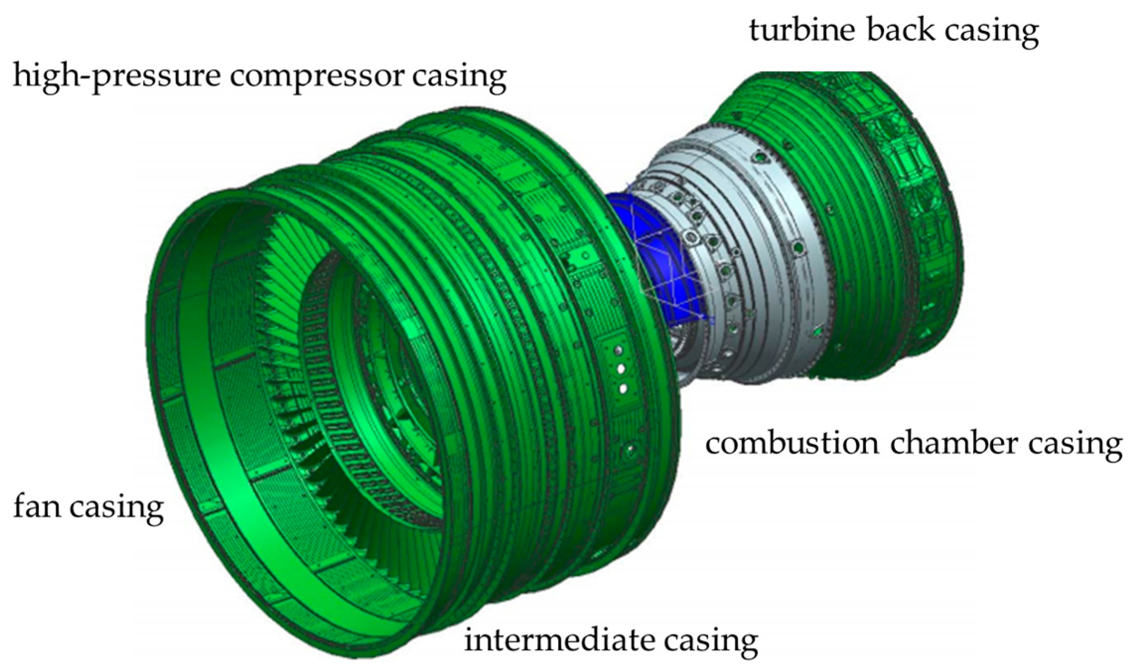
A newly developed aero-engine casing was tested in the experiment, which includes a fan casing, an intermediate casing, a high-pressure compressor casing, a high-pressure turbine casing, a combustion chamber casing, and a turbine back casing, as shown in
Figure 1. To verify the modal results of the experiment, the numerical simulation was carried out first, and the natural frequency of the whole engine casing was calculated by the finite element method.
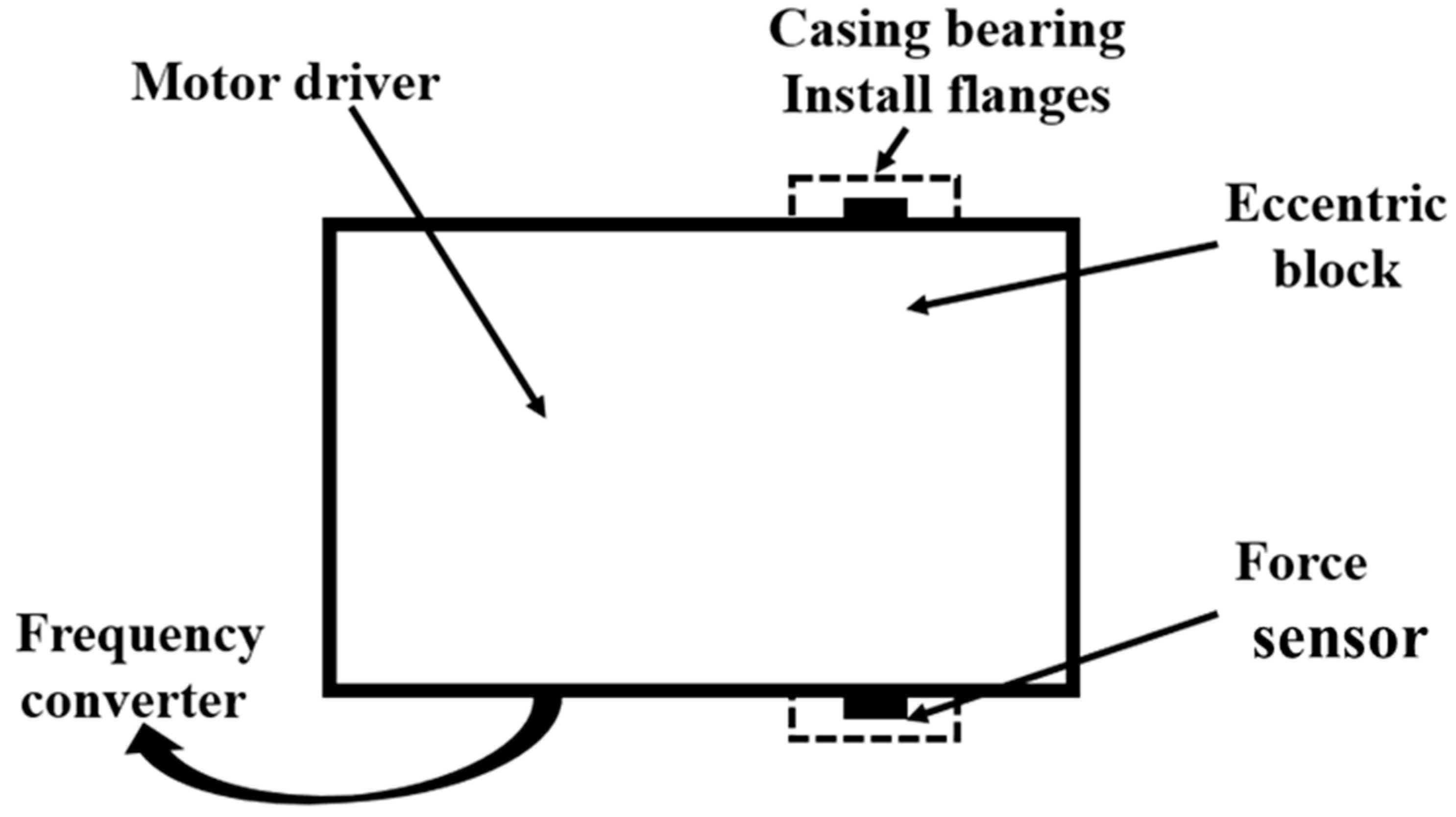
During experiments, the exciting force generated by the rotor is simulated by a rotating force exciter, which is installed at the bearing location on the casing. The rotating force exciter will be employed in the following experiments. The rotating force exciter is used to replace the rotor of the aero engine to generate the rotating force. The rotating force exciter mainly consists of an eccentric block, motor drive, frequency converter, force sensor, and casing bearing install flanges.
Figure 2 shows the rotating force exciter’s system block diagram. The new type of rotating force exciter includes motor driver, casing bearing, eccentric block, and force sensor. The test rig for the experiment of whole engine vibration is installed, where the rotating exciter is fixed at the location of the bearing, and in this case the rotating components such as rotor could be ignored. The maximum operation rotational speed of the rotating force exciter can reach 20,000 r min
−1, and the maximum amplitude of exciting rotational force is 2000 N. The first critical speed of the rotating force exciter is 39,000 r min
−1. The force sensors are arranged in the circumferential direction around the exciter and are the unique connecting structure between the exciter and the casing bearing install flanges. So, the force from the exciter to the test casing can be measured. The outlook of the rotating force exciter is presented in
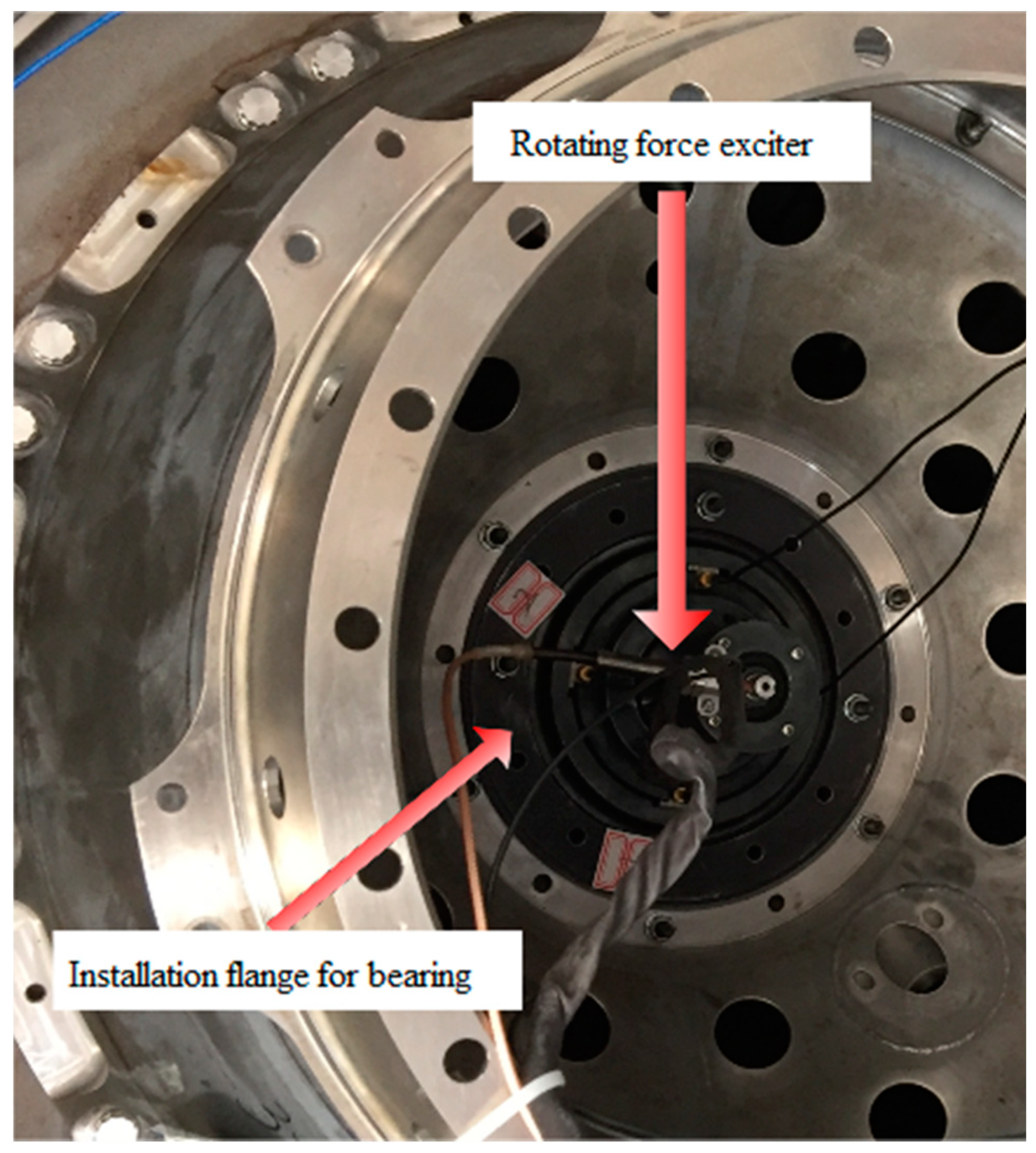
Figure 3.
The detailed installation status for the aero engine is shown in
Figure 3. The rotating force exciter is located in the center, fixed by the flange, and connected by bolts in the circumferential direction. The flange and connecting bolts are the aero engine’s structure for bearing.
3. Results and Discussion
3.1. The Experiment Processing and Vibration Transmission Characteristics Acquiring Method
The experiment for vibration transmission characteristics of the aero-engine casing is designed to obtain the vibration transmission ratio of the casing and the vibration sensor layout of the engine. As shown in
Figure 4, in this experiment, the rotating force exciter is installed at four bearing support locations for the aero engine, and a frequency converter controls the speed of the rotating force exciter. The unbalanced mass’s size controls the exciter’s exciting rotating force. Acceleration sensors are placed in the horizontal and vertical positions on the exterior of the fan casing, the combustion chamber casing, and the turbine back casing. On the left side of the inner surface for the intermediate casing, five tri-axial acceleration sensors are placed 45 degrees apart, evenly. An acceleration sensor is arranged in the radial positions of the No. 1 bearing, No. 2 bearing, No. 3 bearing, and No. 5 bearing. The characteristics of the acceleration sensors are listed in
Table 1.
Firstly, we installed the rotating force exciter in the aero-engine casing’s No. 1 bearing position, controlling the rotating force exciter to accelerate to 15,000 r min−1, recording the vibration acceleration response of each measuring point during the process. According to the above steps, we installed the rotating force exciter in the aero-engine casing’s No. 2, No. 3, and No. 5 bearing positions in turn and recorded the vibration acceleration response of each measuring point. Then, we loosened the casing side of the screws in turn and then, according to the above steps, measured the vibration acceleration response of each measuring point when the exciter was installed in the No. 1, No. 2, No. 3, and No. 5 bearings.
In this test, the vibrational transmission
Y is used to evaluate the vibration transmission characteristics of the casing:
where
F is the exciting rotating force vector generated by the rotating force exciter, and
G is the acceleration vector, including amplitude and phase information for the frequency of the rotating force, with a unit of m s
−2.
3.2. Experimental Analysis of the Natural Frequency of the Aero Engine
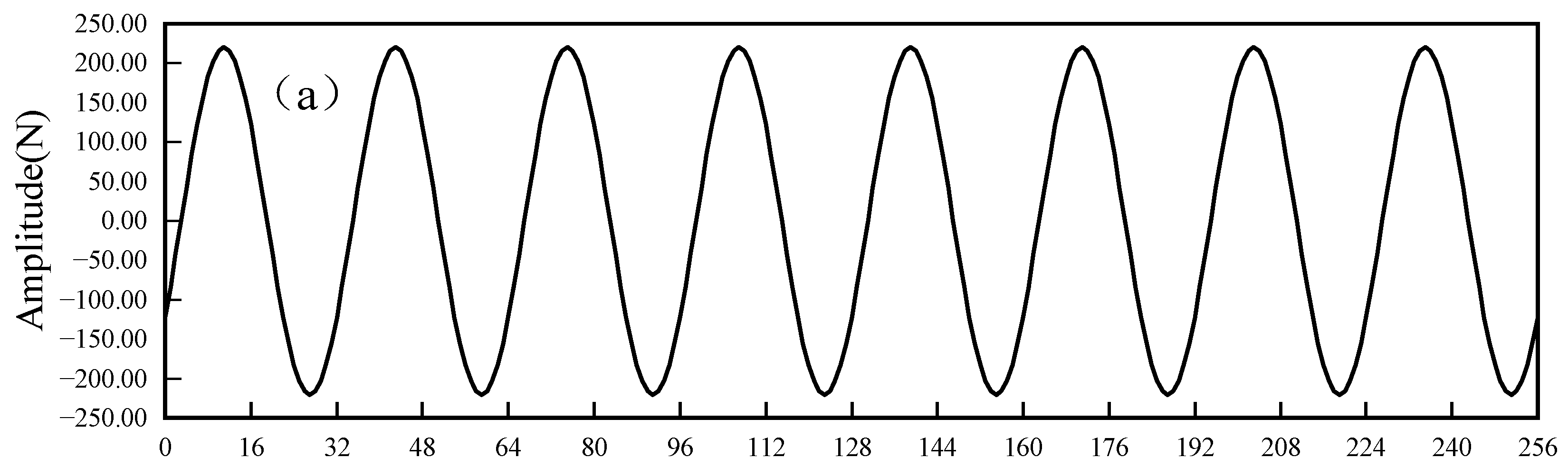
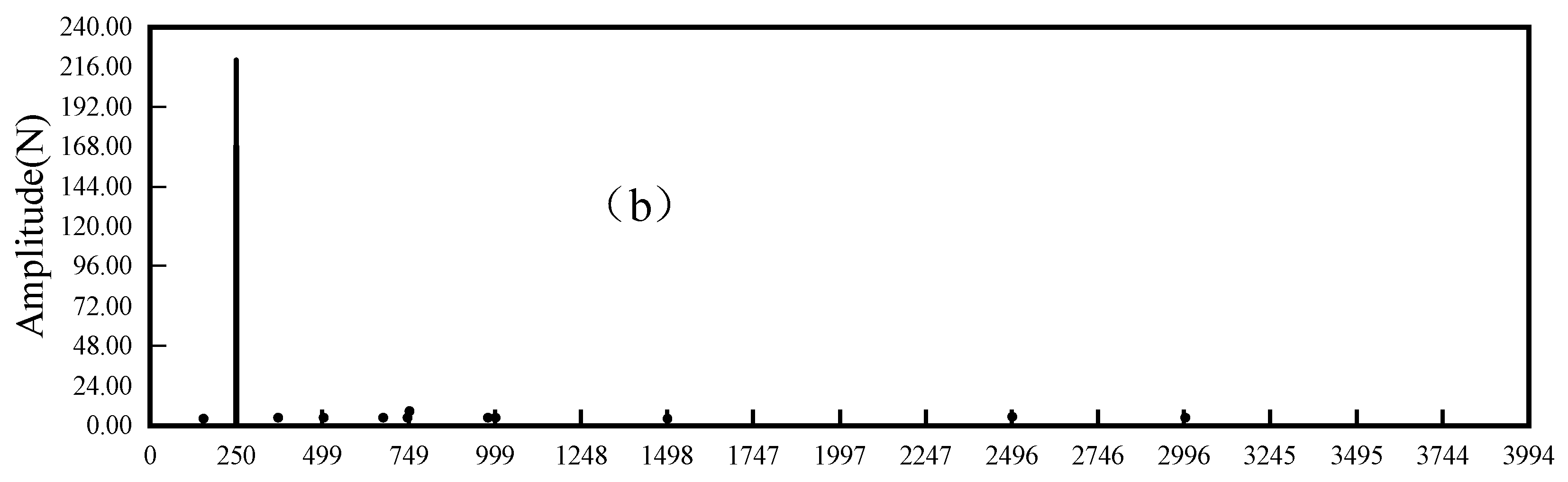
The rotating force varying with time is presented in
Figure 5a, and the frequency spectral for force data is shown in
Figure 5b. It indicates that the rotating force exciter could generate periodic rotating force. The rotating speed of the exciter for
Figure 6 is 15,000 r min
−1.
The acceleration varying with time is presented in
Figure 6a, and the frequency spectral for acceleration data is shown in
Figure 6b. The acceleration of the casing is excited by the exciter. The amplitude is about 40 m s
−2 and for every period.
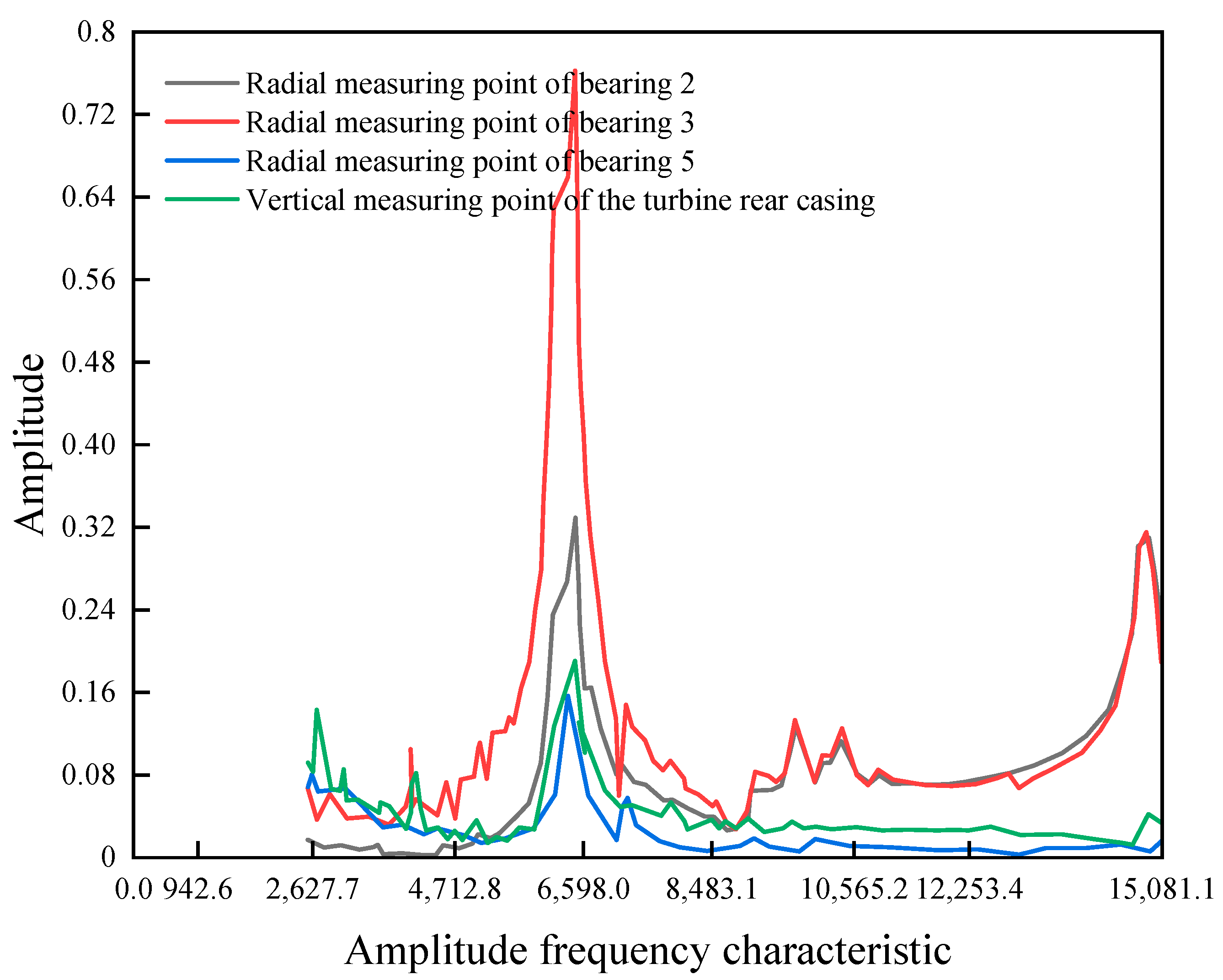
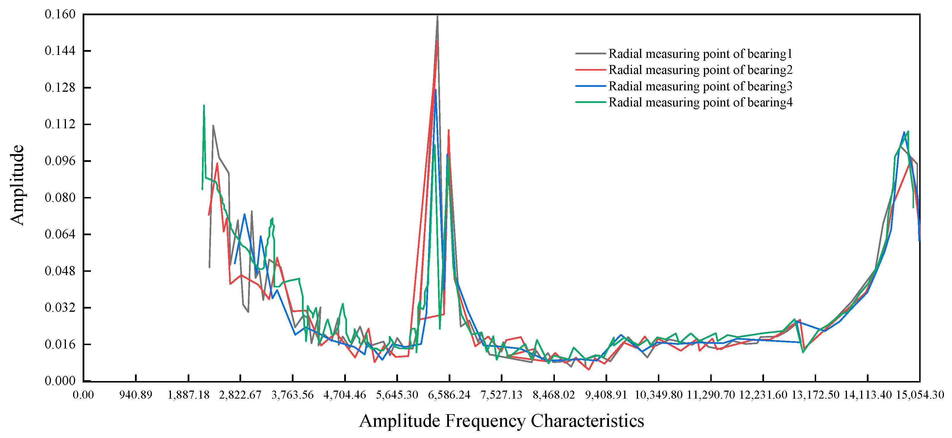
Figure 7 shows the vibration acceleration transmission amplitude’s value of the measuring point of the casing. The rotating force exciter is located at bearing No. 5. The purple line is the curve of the radial measuring point of bearing 2, the brown line is the curve of the radial measuring point of bearing 3, the yellow line is the curve of the radial measuring point of bearing 5, and the green line is the of the vertical measuring point of the turbine rear casing.
The vibration acceleration transmission of each measuring point on the whole aero-engine casing measured by the experiment presents the peak value at 6400 r min−1. However, at 9000 r min−1 and 15,000 r min−1, the vibration acceleration of the measuring points appears to peak only at the front of the aero-engine casing (the side of the fan casing). Therefore, the first-order natural frequency of the casing is 107 Hz, and a local natural frequency appears at the front of the aero engine at 150 and 250 Hz (there are many local modes at other parts of the casing and not presented in detail in the paper). We used ABAQUS 2022 to analyze the modal characteristic of the studied casing. The first natural frequency of the aero-engine casing is 108 Hz, which is very close to the measured value of 107 Hz.
3.3. The Vibration Transmission Characteristics of Measuring Points for the Engine Casing
By analyzing the vibration acceleration value of each measuring point, which is excited at the different bearing positions, some interesting conclusions are presented below:
- 1.
The radial measuring point of bearing No. 1 is more suitable for detecting the rotor running condition than the fan case.
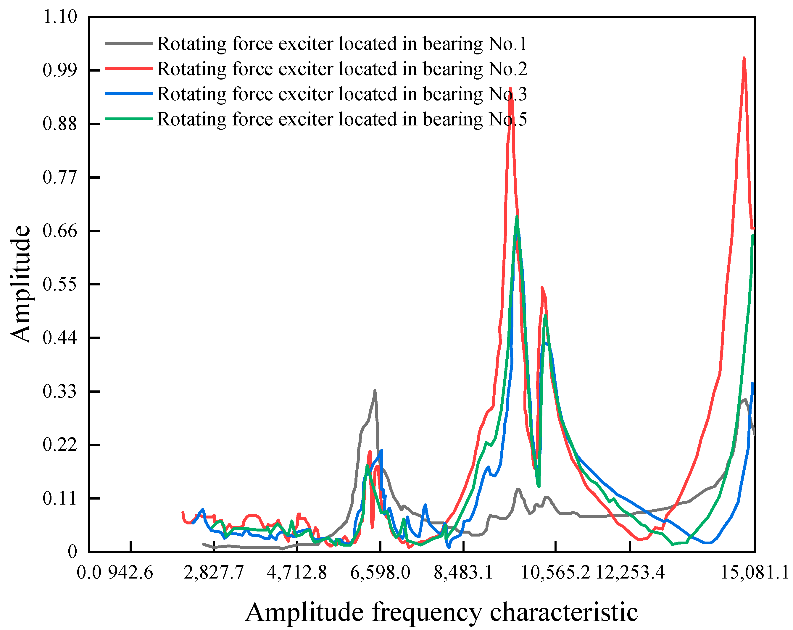
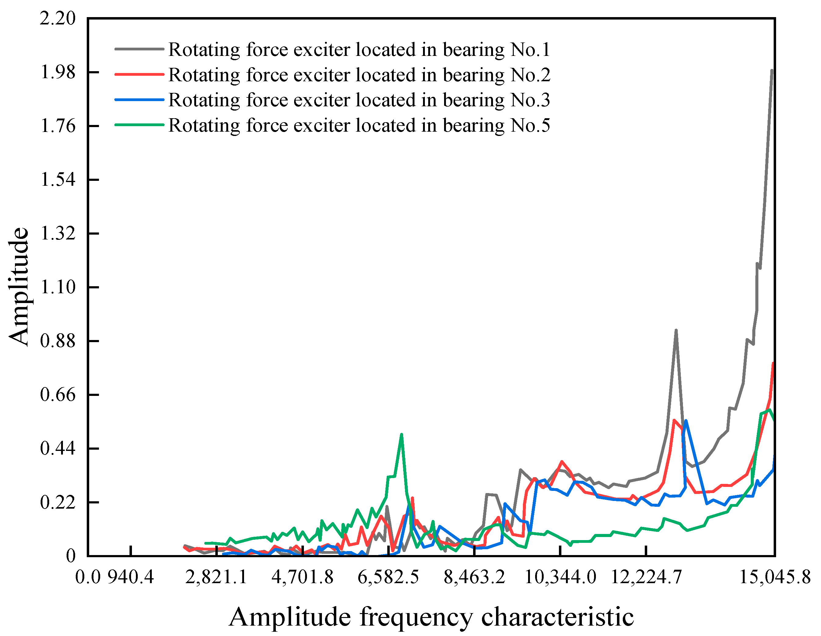
Figure 8 shows the curve of the transmission ratio amplitude frequency diagram of the radial measuring point of bearing No. 1 when the rotating exciter is located in bearing No. 1, bearing No. 2, bearing No. 3, and bearing No. 5.
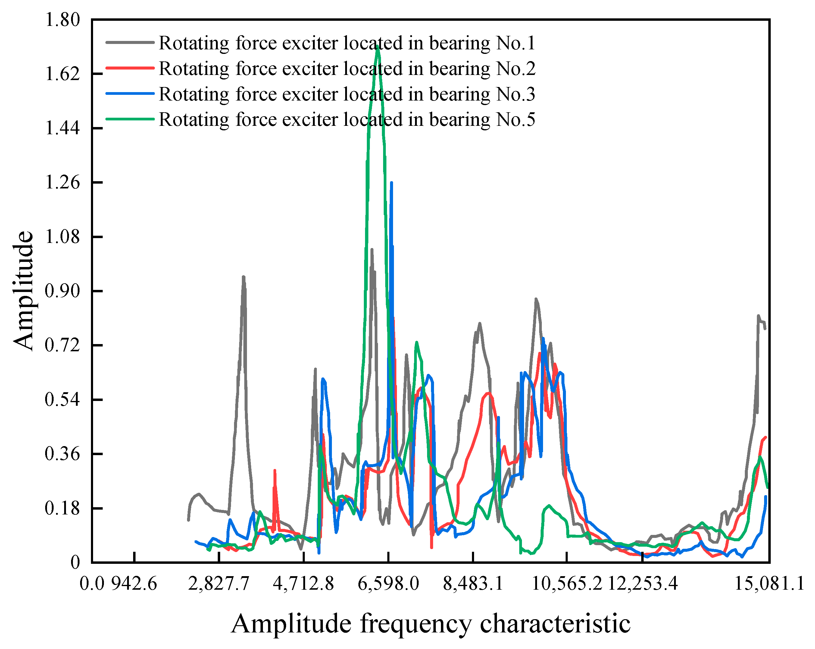
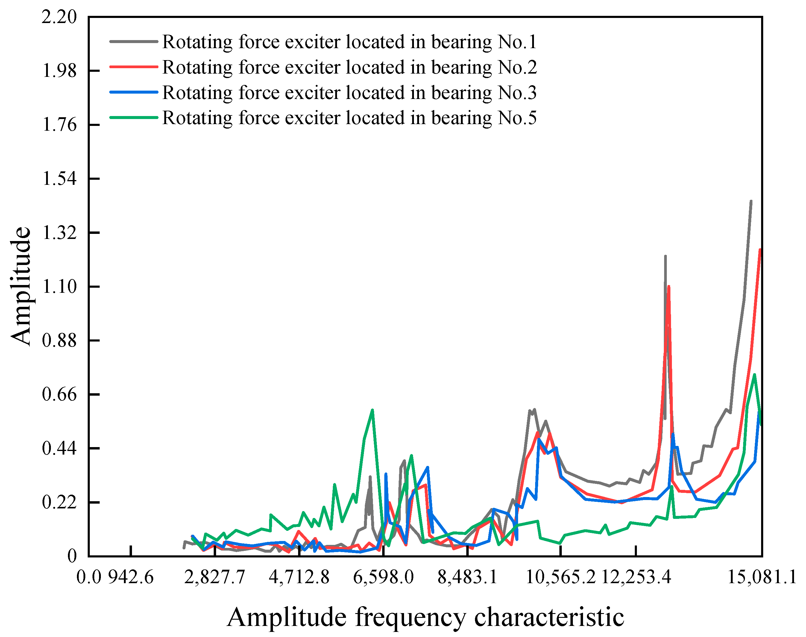
Figure 9 shows the curve of the transmission ratio amplitude frequency diagram for the vertical measuring point of the fan casing when the rotating exciter is located in bearing No. 1, bearing No. 2, bearing No. 3, and bearing No.5.
It shows many peaks and local modes of the vibration acceleration transmission ratio value of the fan casing measurement point. The test fan casing is a simplified casing that removes multiple auxiliary devices. The structure of the actual aero-engine fan casing is more complex, and the local mode will be more difficult. Hence, although the fan is relatively easy to arrange for the sensor measuring point, it cannot truly represent the vibration of the rotor during operation. The vibration acceleration transmission ratio value of the radial measuring point of bearing No. 1 is stable. It has no peak value before 6000 r min−1, so it is more suitable to detect the running state of the fan rotor.
- 2.
The measuring points of the combustion chamber are not suitable for vibration measurement because of the local modes.
Figure 10 shows the curve of the vibration acceleration transmission ratio value of the horizontal measuring point of the combustion chamber when the rotating exciter is located at different bearing locations.
Figure 11 shows the vibration acceleration transmission value of the vertical measuring point of the combustion chamber when the rotating exciter is located in different bearing locations. It can be seen that the vibration acceleration transmission value of the combustion chamber measuring points appears at a peak when the rotation speed of the rotating exciter reaches 9500 r min
−1 and 13,000 r min
−1. Although the combustion chamber is closer to the high-pressure rotor, it is not suitable for detecting the running state of the high-pressure rotor.
- 3.
Although the distance between the measuring points on the intermediate casing is close, the vibration acceleration transmission ratio is different, and the running state of the high-pressure rotor can be presented well.
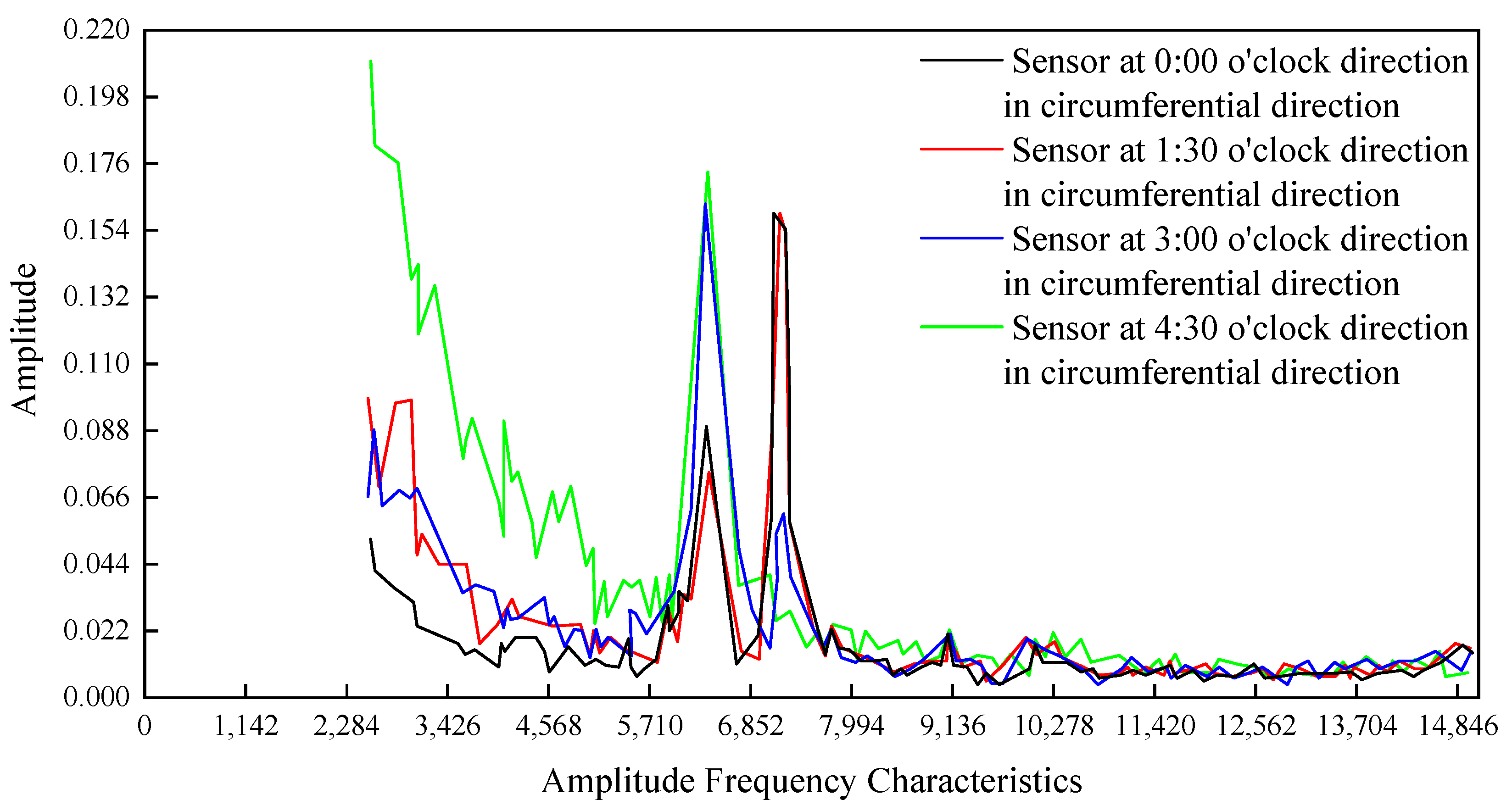
Figure 12 shows the curve of the vibration acceleration transmission value of the measuring point on the intermediate casing when the rotating force exciter is located at bearing No. 3.The red line is the acceleration transmission ratio curve of the horizontal measuring point at the 0 o’clock direction on the intermediate casing, the brown line is the acceleration transmission ratio curve of the horizontal measuring point at the 1:30 direction on the intermediate casing, the yellow line is the acceleration transmission ratio curve of the horizontal measuring point at the 3 o’clock direction on the intermediate casing, and the green line is the acceleration transmission ratio on the horizontal measuring point at the 4:30 direction of the intermediate casing. It can be seen from the figure that each measuring point is different when the rotation speed of the rotating force exciter is lower than 6500 r min
−1. In comparison, the vibration acceleration transmission value is smooth and has no peak when the rotation speed is higher than 8000 r min
−1. Because bearing No. 3 supports the high-pressure rotor of the aero engine, the measuring point on the intermediate casing is suitable for detecting the running state of the high-pressure rotor. However, the inner ring stiffness of the intermediate casing is significant, so the vibration limit value should be relatively lower.
- 4.
Bolt loosening of the flange has little effect on the vibration transmission characteristics of the casing.
The test was conducted to change the status of the three flanges on the intermediate casing, combustion casing, and rear turbine casing. To accomplish this, three methods were used for each flange. For the 10 o’clock direction, three bolts were loosened; for the 10 o’clock and 4 o’clock directions, three bolts were loosened; and for the 10 o’clock and 2 o’clock directions, three bolts were loosened.
Figure 13 illustrates the vibration acceleration transmission ratio curve of the upper measuring point of the rear turbine casing when the flange of the intermediate casing is under different conditions, with the four lines representing the four tightened states of the casing flange. It is evident that bolt loosening of the flange has a slight effect on the vibration transmission characteristics. The loosening of the bolts on the flanges not only changed their status but also had a slight effect on the vibration transmission characteristics of the rear turbine casing. This is important information because it helps engineers understand how the flanges and the bolts interact with each other and the overall vibration transmission characteristics. It can also help engineers to make decisions on how to optimize the flange and bolt design for a particular application. In addition, the test results can also be used to inform the design and installation of flanges for other applications. For instance, engineers can use the results to determine the best combination of bolts, flanges, and materials that will provide the optimal vibration transmission characteristics for a particular application. This information can then be used to create a more efficient and effective design for the flanges and bolts.
Overall, the testing of the flanges and bolts has the potential to greatly improve the vibration transmission characteristics of the rear turbine casing and other applications. By providing engineers with the information needed to make informed decisions, the test results can help to ensure that flanges and bolts are designed and installed in the most efficient and effective manner possible.


