Article

Grouping Control Strategy for Battery Energy Storage Power Stations Considering the Wind and Solar Power Generation Trend

1
State Grid Hebei Economic Research Institute, Shijiazhuang 050023, China
2
School of Electrical Engineering, North China Electric Power University, Baoding 071000, China
*
Author to whom correspondence should be addressed.
Energies 2023, 16(4), 1857; https://doi.org/10.3390/en16041857
Submission received: 11 January 2023 / Revised: 28 January 2023 / Accepted: 8 February 2023 / Published: 13 February 2023

Abstract

:
For the optimal power distribution problem of battery energy storage power stations containing multiple energy storage units, a grouping control strategy considering the wind and solar power generation trend is proposed. Firstly, a state of charge (SOC) consistency algorithm based on multi-agent is proposed. The adaptive power distribution among the units started can be realized using this algorithm. Then, considering the trend of wind and solar power generation, a reasonable grouping control strategy is formulated. The grouping situation of the units is determined by using the probability distribution characteristics of energy storage charging and discharging, which reduces the number of charging and discharging conversions and extends the power station life. Finally, the actual data of a wind–solar energy storage microgrid is used to verify the method. The simulation results demonstrate that the proposed method has certain advantages in terms of control effect, SOC consistency, and extending the power station life.

1. Introduction

Battery energy storage is one of the important means to solve the problem of new energy consumption because of its strong power regulation ability and flexible configuration [1,2]. In practical application, large-scale battery energy storage power stations are often composed of multiple battery energy storage units. Therefore, how to distribute the power reasonably among the units is the key to ensure the optimal operation of the energy storage power station [3,4].
At present, most of the research focuses on single energy storage systems [5,6] and hybrid energy storage systems [7,8] and considers a certain energy storage medium as a whole, but does not involve research on detailed power allocation among multiple units. A detailed study on optimal power allocation among units was presented in the reference [9], and a whale optimization algorithm based on adaptive weight and a simulated annealing strategy was proposed for power distribution of an all-vanadium redox flow battery energy storage system. An improved state of charge (SOC) droop control method based on a multi-agent system was proposed in the reference [10] to achieve the SOC balance of multiple units. In the references [11,12,13], the SOC balance was studied and the power of each energy storage unit was adjusted dynamically according to the SOC. An optimal power allocation strategy among multiple units considering the life of batteries was put forward in the reference [14], and a mixed integer programming algorithm was used to solve the problem. The concept of SOC balance was proposed in the reference [15], and the power of each unit was distributed based on this concept. However, the above distribution strategy required all the energy storage units to participate in the response. Due to the volatility of new energy, the energy storage units need to be charged and discharged frequently, which leads to significant life loss for the units.
Therefore, Nguyen C L proposed a dual battery energy storage system (BESS), one BESS for charging and the other for discharging. Two BESSs with different charging and discharging states were adopted to stabilize the wind power fluctuation and extend the life of battery energy storage [16]. Lin proposed a control strategy of adaptively fine-tuning the first-order low-pass filtering time constant to optimize the SOC of two battery packs [17]. Long Benjin put forward a grouping control strategy for energy storage units, which can improve the operation efficiency [18]. Considering the life loss of the energy storage units, Yu Yang extracted the wind power trend and divided the units into two battery packs to extend the energy storage service life [19]. On the basis of the dual-battery structure, Guo Wei studied the distributed coordinated control of the energy storage array system containing multiple batteries, considering the power distribution among multiple units [20].
In the above research, the BESS is divided into two battery groups: the charging group and the discharging group. Compared with the overall response of battery energy storage, it reduces the frequent conversions between charging and discharging states, and improves the power station service life to some extent. However, the current grouping method is average grouping; that is, the two groups contain the same number of energy storage units. This grouping method does not consider the inconsistency of the charging and discharging fluctuation energy of the power station. The battery energy storage units have more temporary conversion times, and the aging of the units is accelerated. In order to further extend the remaining service life of the battery energy storage power station, this paper puts forward a grouping control strategy for the power station considering the wind and solar power generation trend. The main contributions are as follows:
(1) A novel grouping strategy for the battery energy storage power station is proposed. Considering the trend of wind and solar power generation, the fluctuation curve of charging and discharging power is obtained. The grouping situation is determined using the probability distribution of the fluctuation situation and SOC size. This grouping method reduces temporary conversion times and prolongs the power station life.
(2) A SOC consistency algorithm based on multi-agent is proposed. The algorithm realizes adaptive power allocation of multiple units and makes the SOC more consistent in the scheduling period.
(3) An energy storage output strategy considering battery life is formulated. First, energy storage units are selected according to SOC priority, and then power distribution is carried out in the selected energy storage units to realize power distribution of the energy storage power station.
The organization of this paper is structured as follows: Section 2 describes the structure of a wind–solar energy storage microgrid system; Section 3 proposes a grouping control strategy for battery energy storage power stations considering the trend of wind–solar power generation; Section 4 shows and analyzes the results of the grouping control strategy through case analysis; Section 5 summarizes the work of this paper and the existing shortcomings, and points out the direction for subsequent related work.

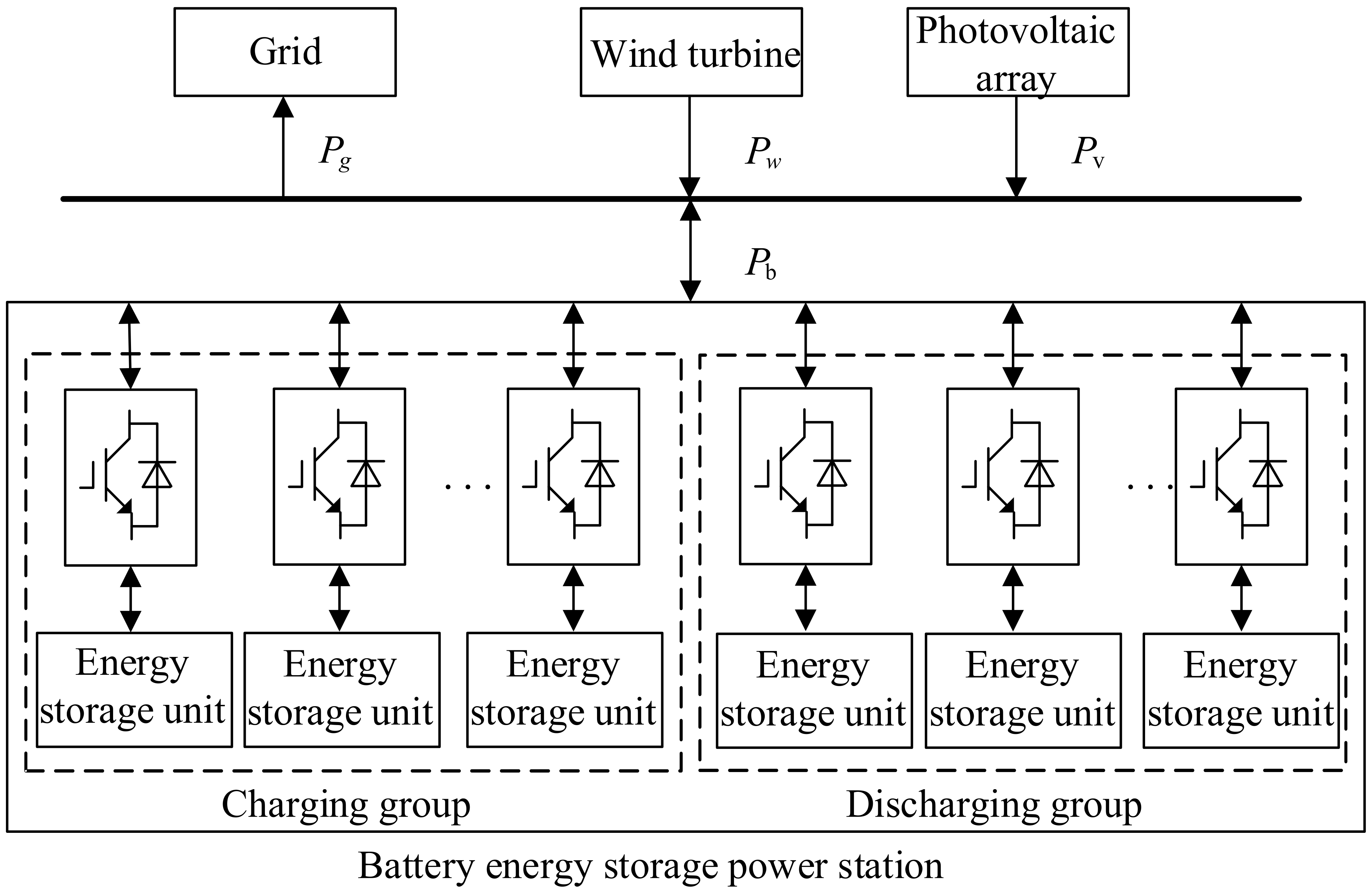
2. Wind–Solar Energy Storage Microgrid System

Take the battery energy storage power station in the wind–solar energy storage microgrid system as an example; its structure is shown in Figure 1. The power station is made up of a number of parallel-connected battery energy storage units, which together constitute an energy storage system of MW level. The units complete the information exchange between adjacent nodes through the distributed communication network.
The power station collects the output power P w of wind turbines and the output power P V of photovoltaic arrays in real time and calculates the total power command P b according to the scheduling instruction P g .
The control center sends the total power command P b to the energy storage units. Each unit decomposes the power command P b by distributed communication and the strategy proposed in this paper, and the power commands P b 1 ,   P b 2 , ,   P b n of each battery unit is calculated in real-time.
It is stipulated that the power of the battery energy storage power station is positive when discharging and negative when charging. The total power command P b of the battery energy storage power station is:
P b = P g P w P v
The wind–solar energy storage system is intended to provide constant power to the power grid by averaging the wind–solar power over the scheduling time interval. In the k th scheduling interval, k T d < t k + 1 T d , and the scheduling instruction P g is the average wind and solar power output in the scheduling interval T d :
P g = 1 T d k T d k + 1 T d P w τ + P v τ d τ
Due to the randomness and volatility of wind and solar power output, battery energy storage power stations need frequent charge and discharge conversions to track the scheduling plan, which will affect the battery life [21,22]. In order to avoid frequent conversion between charging and discharging states, energy storage units are divided into a charging group and a discharging group. When the total power command is discharging, the discharge group starts first; otherwise, the charging group starts first.

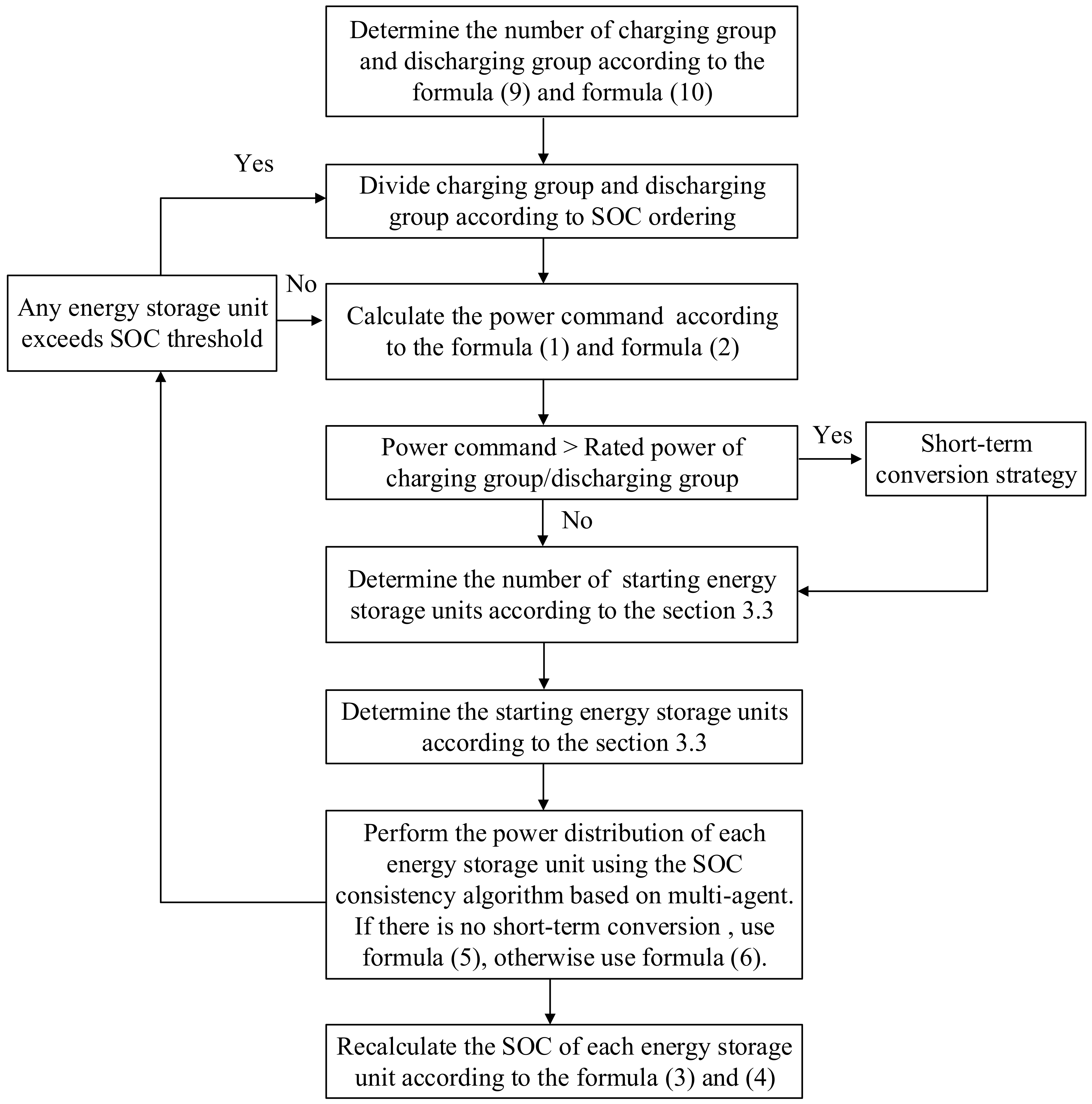
3. Power Distribution of Battery Energy Storage Power Stations Considering the Wind and Solar Power Generation Trend

3.1. SOC Consistency Algorithm Based on Multi-Agent

In order to realize the adaptive distribution of power commands, an SOC consistency algorithm based on multi-agent is used in this paper.
In a multi-agent system, the connection relationship among agents is represented by the topological graph G = V , E , A , where V = 1 , 2 , , N represents the non-empty point set composed of N agents, E = V × V represents the edge set composed of ordered node pairs, and A = a i j R n × n represents the adjacency matrix between agents in the multi-agent system. If i ,     j E , that is, agent j can receive the information transmitted from agent i through the communication topology, then a i j = 1 ; if agent j cannot receive the information from agent i through the communication topology, then a i j = 0 [23,24,25].
The energy storage unit exchanges information based on the communication network, and achieves the goal by coordinating charging and discharging. The battery energy storage power station composed of N energy storage units can be regarded as a multi-agent system composed of N agents. a i j is related to the grouping state of energy storage units. Information is exchanged among energy storage units in the same group, and the physical characteristics of energy storage units, such as output power and SOC, are taken as the state of each agent. By designing a reasonable control strategy to control these physical states, we can achieve our expected results.
The state of charge S O C i t of the i th energy storage unit at time t can be expressed as [26,27]:
S O C i t = E i t E N
E i t = E i t 1 η b c t 1 t P b i τ d τ ,   P b i τ 0 E i t 1 1 η b d t 1 t P b i τ d τ ,   P b i τ 0
Based on the multi-agent consistency theory, the following control strategies are designed:
  P i t = P b m + μ j N i a i j d i S O C i t d j S O C j t
When the rated power of one group is insufficient to support the power demand, some units in another group need to temporarily participate and provide support. At this time, the temporarily added energy storage units can contact with the battery units in the original group. The power instruction of the units is:
P i t =       P m       W i = 0   and   P b 0 P m       W i = 0   and   P b < 0       P b P N m N b +   W i = 1   and   P b 0 μ j N i a i j W i d i S O C i t W j d j S O C j t   P b + P N m N b +       W i = 1   and   P b < 0 μ j N i a i j W i d i S O C i t W j d j S O C j t
In addition, it is necessary to limit the SOC and transmission power of the energy storage units, as shown in Formulas (7) and (8).
S O C m i n S O C i t S O C m a x
P m P i t P m
According to Formulas (5) and (6), when the energy storage power station is charging, the energy storage units with smaller SOC absorb more power, while those with larger SOC absorb less power; when the energy storage power station is discharging, the energy storage units with larger SOC emit more power, while those with small SOC emit less power. Finally, the SOC of the energy storage units will be gradually balanced.

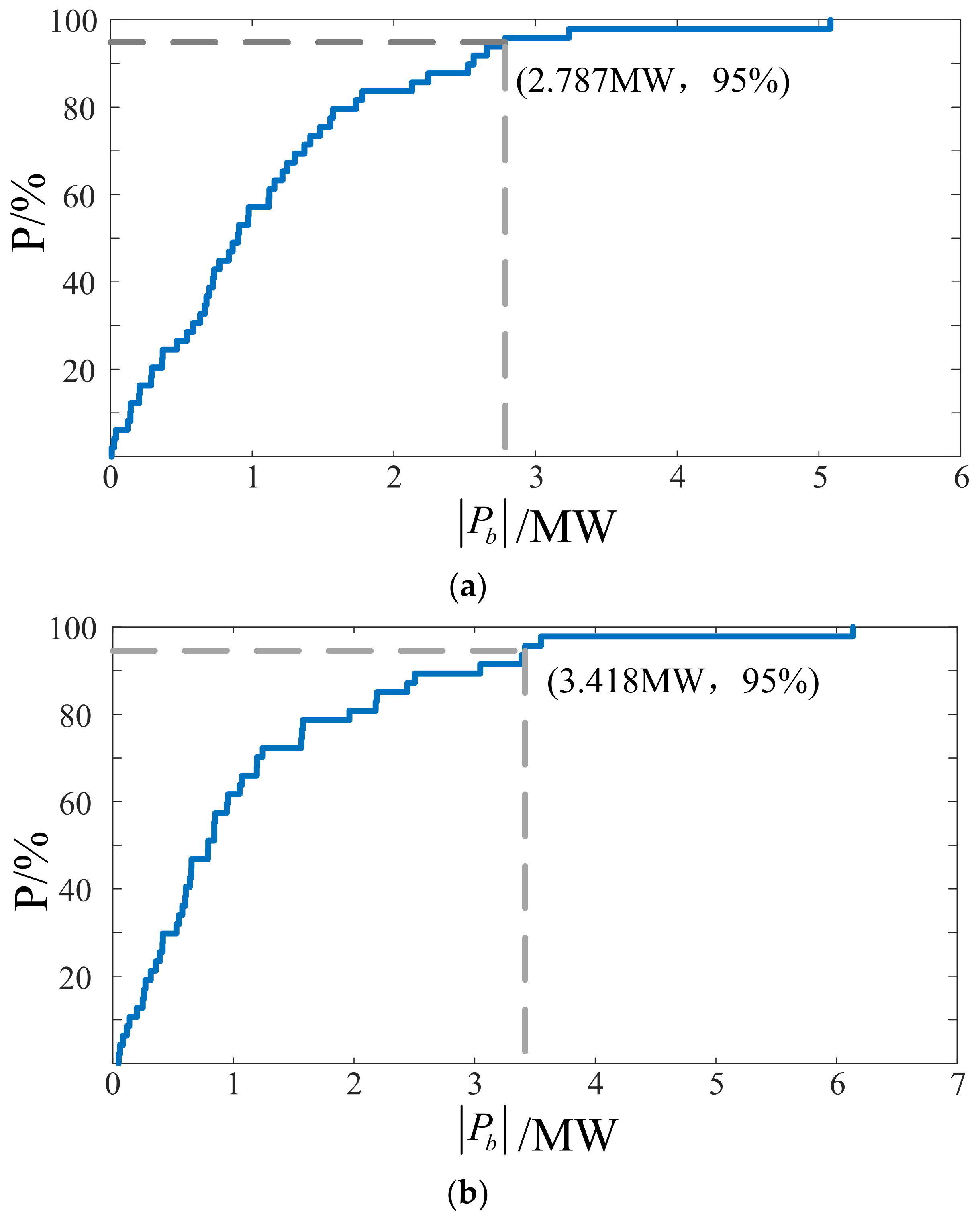
3.2. Determining Energy Storage Charging and Discharge Grouping Situation Based on Probability Distribution

The deviation between scheduling instruction and wind and solar power is taken as the power command. However, the ratio of positive and negative fluctuation probability of the power is not fixed at 1:1, which is related to the fluctuation curve of wind and solar power. Therefore, the capacities of the charging group and the discharging group are not exactly the same.
In order to determine the number of energy storage units of the charging and the discharging group, the trend of wind and solar power output is considered, and the wind and solar power curves of the previous day are predicted. According to the scheduling instruction generation principle, the power command of the previous day is predicted, and the grouping situation is determined according to the power fluctuation probability of the power command. Because prediction is not the focus of this paper, in order to simplify the processing, the actual collected data is used instead of the predicted data.
Under the condition that the capacity of the battery energy storage power station is fixed, in order to reduce the conversion times, it is required that the energy storage unit will not conduct temporary switching of charging and discharging in most cases; that is, the ratio δ of the charging group and discharging group will be determined according to the following formula:
δ = F b c 1 β F b d 1 β
where the functions F b c 1 β and F b d 1 β are the inverse functions of the cumulative probability distribution function of the predicted charging and discharging power fluctuation amplitude, respectively; β is a relatively large probability level specified in advance.
On this basis, according to Formula (10), the number of units contained in the charging group N b = N b c and the number of units contained in the discharging group N b = N b d are determined:
N b c = δ N N b d = N N b c
where [ · ] means rounding.
Each energy storage unit is numbered fixedly, and all energy storage units are arranged in ascending order of SOC. Combined with the number of energy storage units, N b c units arranged in the front are selected as the charging group, and the remaining N b d units arranged in the back are selected as the discharging group.

3.3. Energy Storage Output Strategy Considering the Degradation Characteristics of Battery Life

In order to improve the overall available power of the energy storage system when the energy storage power station operates in the grouping mode, the following coordination strategies are used to reduce the conversion times and delay the aging of the energy storage units. The power distribution process is shown in Figure 2.
According to Section 3.2, the rated power of the charging group is P N = P b c = N b c P m , and the rated power of the discharging group is P N = P b d = N b d P m . We can calculate the total power command P b according to Formula (1).
(1)
When the power station is in a non-discharge state ( P b t 0 )
① When P b t P b c
The rated power of the charging group can meet the power demand, and the energy storage units of the discharging group do not need to be temporarily converted into the charging state. The state transition identifiers W i of all energy storage units are all 0. When P b t = 0 , all energy storage units are in the standby state, and d i is set to 0; when 0 < P b t P m , an energy storage unit is started and charged by the unit with the lowest SOC in the charging group; when 0 < P b t 2 P m , the two energy storage units are started and charged by the two units with the lowest SOC in the charging group; and so on, until all the energy storage units in the group are started. All selected units d i are set to 1, and the rest are set to 0.
② When P b t > P b c
If the rated power of the charging group cannot meet the power demand, a short-term conversion strategy will be adopted. The energy storage units with small SOC in the discharging group will be temporarily added to the charging group, and the number of temporarily added units is determined as the same as ① in (1). The state transition identifiers W i of the units selected to temporarily undertake the charging task are set to 1, and the rest are set to 0. The starting identifiers d i of all charging group energy storage units and temporarily converted discharging group energy storage units are set to 1, and the rest are set to 0.
(2)
When the power station is in a discharge state ( P b t > 0 )
① When P b t P b d
The rated power of the discharging group can meet the power demand, and the energy storage units of the charging group do not need to be temporarily converted into the discharge state. The state transition identifiers W i of all energy storage units are all 0. When 0 < P b t P m , an energy storage unit is started and discharged by the unit with the highest SOC in the discharging group; when 0 < P b t 2 P m , the two energy storage units are started and discharged by the two units with the highest SOC in the discharging group; and so on, until all the energy storage units in the group are started. All selected units d i are set to 1, and the rest are set to 0.
② When P b t > P b d
The rated power of the discharging group cannot meet the power demand, so a short-term conversion strategy will be adopted. The energy storage units with higher SOC in the charging group will be temporarily added to the discharging group, and the number of temporarily added units is determined as the same as ① in (2). The state transition identifiers W i of the units selected to temporarily undertake the discharge task are set to 1, and the rest are set to 0. The starting identifiers d i of the discharging group energy storage units and temporarily converted charging group energy storage units are set to 1, and the rest are set to 0.
In the process of operation, when the SOC of energy storage units in any group reaches the thresholds, the charging and discharging groups will be redivided according to the SOC ordering.

4. Simulation Analysis

4.1. Scene Description and Parameter Setting

The measured data of a wind–solar energy storage microgrid system in northern Hebei were selected, for which the rated capacity of the wind generator was 20 MW and the photovoltaic power generation was 15 MW. The battery energy storage power station was composed of 20 energy storage units. The set parameters of the power station and the initial SOC of each unit are shown in Table 1 and Table 2, respectively, and the total capacity of the power station was 6 MW/24 MW∙h.
The 24 h wind and photovoltaic power data were selected for simulation verification. The data sampling interval was 15 min, and the scheduling interval was 1 h. The scheduling instruction P g was obtained according to Formula (2), and the total power generation of the photovoltaic and wind turbine and the scheduling curve are shown in Figure 3. There is a deviation between the wind–solar power curve and the scheduling instruction curve. It is necessary for the power station to make up for the deviation. The energy storage power curve obtained according to Formula (1) is shown in Figure 4. Due to the fluctuation of wind and solar power, the power command changes frequently in positive and negative directions. The power station needs frequent charging and discharging conversions to track the scheduling instruction, which is a great loss to the life of the station, so the energy storage units were divided into two groups.

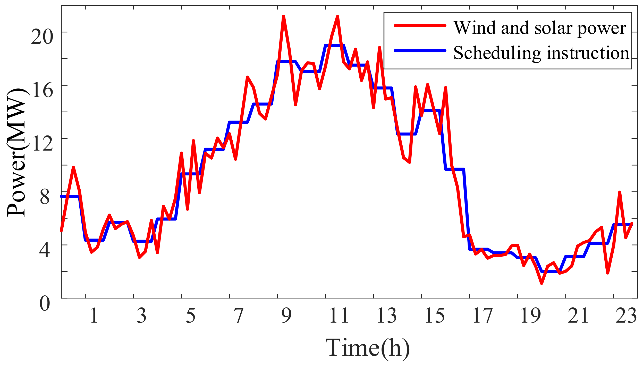
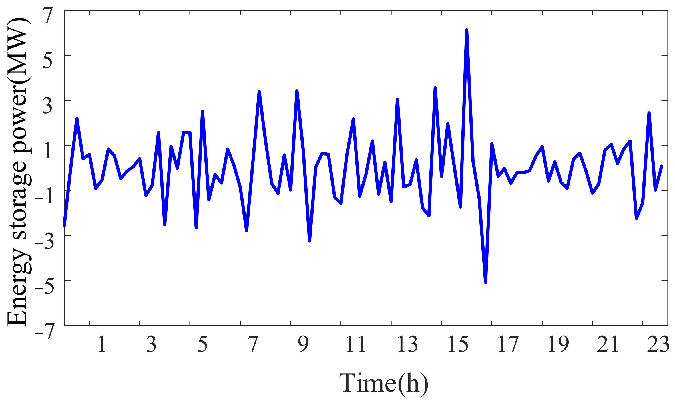
4.2. Simulation Results

The grouping situation of energy storage was determined according to the method in Section 3.2. The statistics for the fluctuation amplitude of the energy storage power curve are shown in Figure 4, and its probability distribution characteristics are shown in Figure 5. β was set to 95%. The maximum fluctuation value during charging was 5.082 MW, and 95% of the fluctuation amplitude was less than 2.787 MW. The maximum fluctuation value during discharging was 6.136 MW, and 95% of the fluctuation amplitude was less than 3.418 MW. The power ratio corresponding to the charging and discharging power amplitude when the cumulative probability was 95% was taken as the ratio of the number of units contained in the two groups. According to Formulas (8) and (9), the ratio δ of the charging group to discharging group was 1/1.226. The total number of energy storage units was 20. There were 9 units assigned to the charging group and 11 units assigned to the discharging group. All the energy storage units were arranged in ascending order of initial SOC, with 9 energy storage units arranged at the front as the charging group and 11 energy storage units at the back as the discharging group.
The control strategy was adopted for power output. The power command P b in the typical day and the actual response results P b according to the control strategy are shown in Figure 6. In order to show the working state of the two groups more intuitively, the power curves of them were separated, as shown in Figure 7.
The SOC values of the units will change in the scheduling cycle, and SOC consistency can reflect the effectiveness of the strategy. Using the grouping method proposed in this paper, the SOC variation curve under the traditional strategy of average power distribution and the multi-agent SOC consistency strategy is shown in Figure 8.
In order to compare the control effects clearly between the optimal grouping strategy and the average grouping strategy (i.e., 10 units in the charging group and 10 units in the discharging group), the rain-flow counting algorithm [28] was used to make statistics on the SOC variation curves of the energy storage units within 24 h under the two strategies, and the statistical results were converted into the equivalent number of cycles under the rated discharge depth by using the calculation method in the literature [29,30]. The results of each unit are shown in Figure 9.

4.3. Simulation Analysis

To verify the effectiveness of the proposed algorithm and control method, the following three aspects were analyzed: control effect, SOC consistency, and energy storage station life.
(1) Control effect: As shown in Figure 6, in the whole operation cycle, the energy storage power station can effectively track power command instructions under the power distribution strategy used in this study. Due to the uncertainty of wind and solar power generation, the power demand may exceed the rated power N P m of the power station, as the situation marked by the circle in Figure 6 shows. The rated power N P m was 6 MW. When the power command exceeded 6 MW, all energy storage units were started and operated at the maximum power. Figure 7 shows that the charging group undertakes the charging task, and the discharging group undertakes the discharging task. The rated power of the discharge group was 3.3 MW, and the charging group was 2.7 MW. When the charging or discharging capacity of a certain group is insufficient, the charging group will temporarily participate in the discharging process, or the discharging group will temporarily participate in the charging process, a short-term conversion strategy is adopted, and another group of energy storage units provides additional power.
(2) SOC consistency: The strategy used in this paper was that only the minimum number of battery cells work at any one time, so the SOC curves of each unit are not completely coincident. When any energy storage units reach the SOC threshold, the two groups will be redistributed. Figure 8 shows that the start-up energy storage units distribute power evenly under the strategy of average power distribution, and the SOC changes at the same speed. However, the multi-agent SOC consistency strategy takes the difference of SOC into account when the energy storage units output power. For example, in the discharge state, the units with larger SOC emit more power, the SOC drops faster, and the SOC values tend to be more consistent in the scheduling period.
(3) Energy storage station life: Considering the fluctuation amplitude of charging and discharging, the optimal grouping method reduces the number of temporary conversions, so the number of daily equivalent cycles is reduced. As can be seen from the analysis of Figure 9, if the rated cycle number of the energy storage units is 1500 times, the maximum daily equivalent cycle number under the optimal grouping strategy is 1.403, which takes about 1069 days. However, the maximum daily equivalent cycle number under the average group strategy is 1.552, which takes about 966 days. The statistics show that the optimal grouping method can extend the power station life to a certain extent compared with the average grouping.

5. Conclusions

To solve the power distribution problem of battery energy storage power stations containing multiple energy storage units, this paper proposed a grouping control strategy for the battery energy storage power station considering the trend of wind and solar power generation, and verified the effectiveness of the method through simulation experiments. The key conclusions were as follows:
(1)
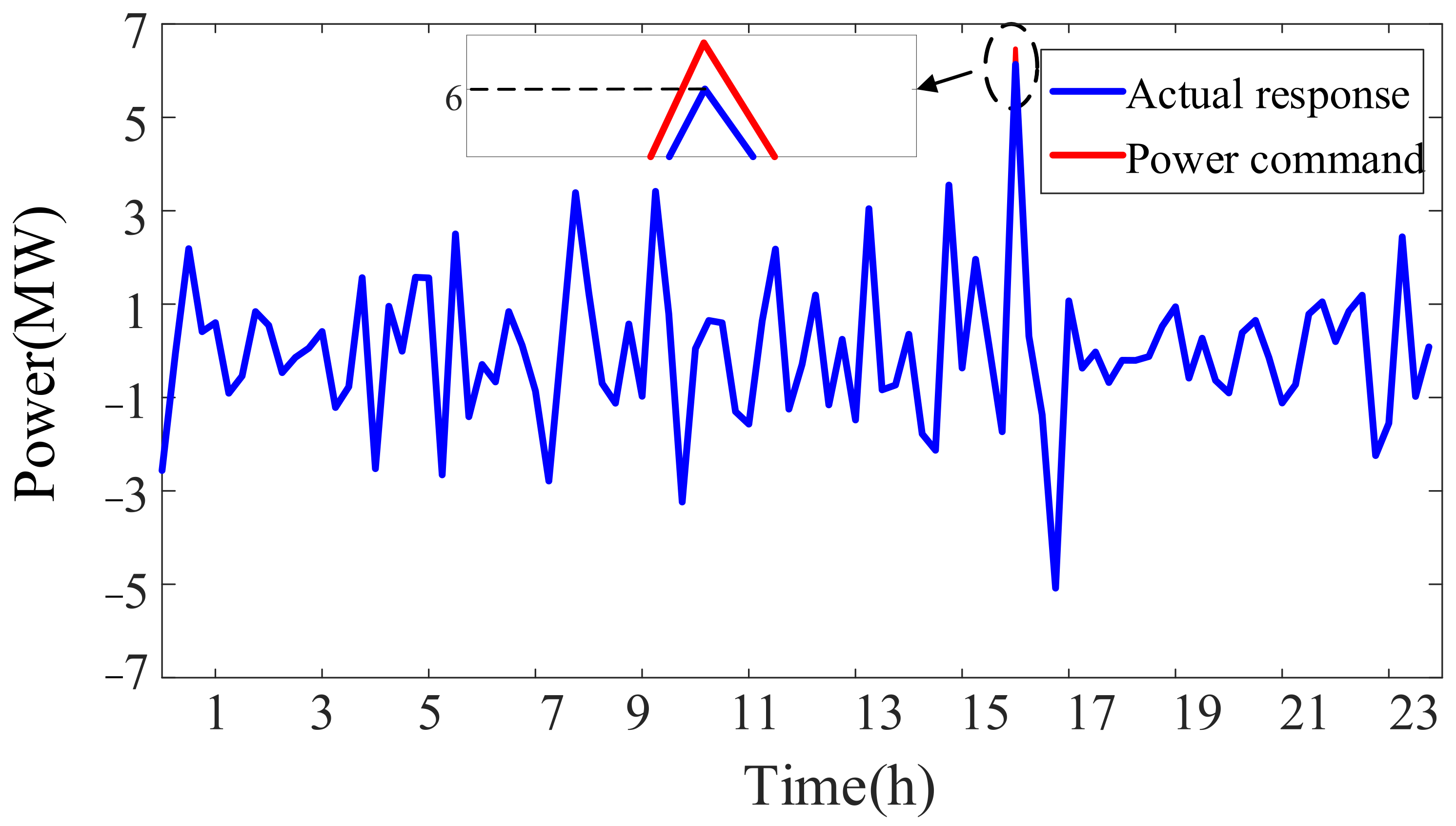
A strategy of energy storage output considering battery life was designed, in which the started energy storage units are selected first, and then the power allocated by each unit is determined. This strategy uses as few battery units as possible and ensures the accurate tracking of the scheduling plan.
(2)
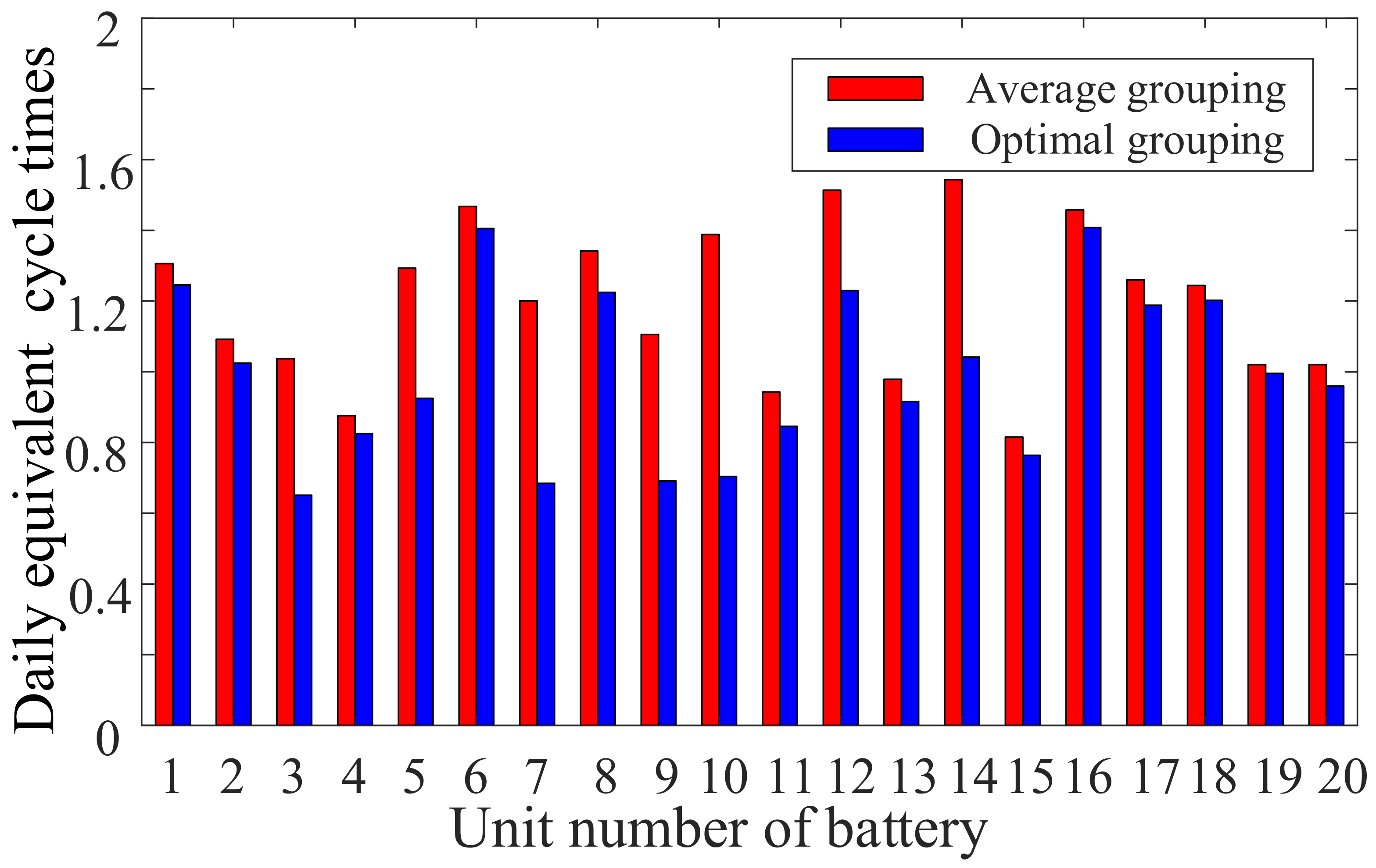
A grouping method considering the positive and negative fluctuation probability of energy storage power was proposed. Compared with the average grouping used in the existing research, it can reduce the temporary conversion times of charging and discharging and further prolong the power station operation life.
(3)
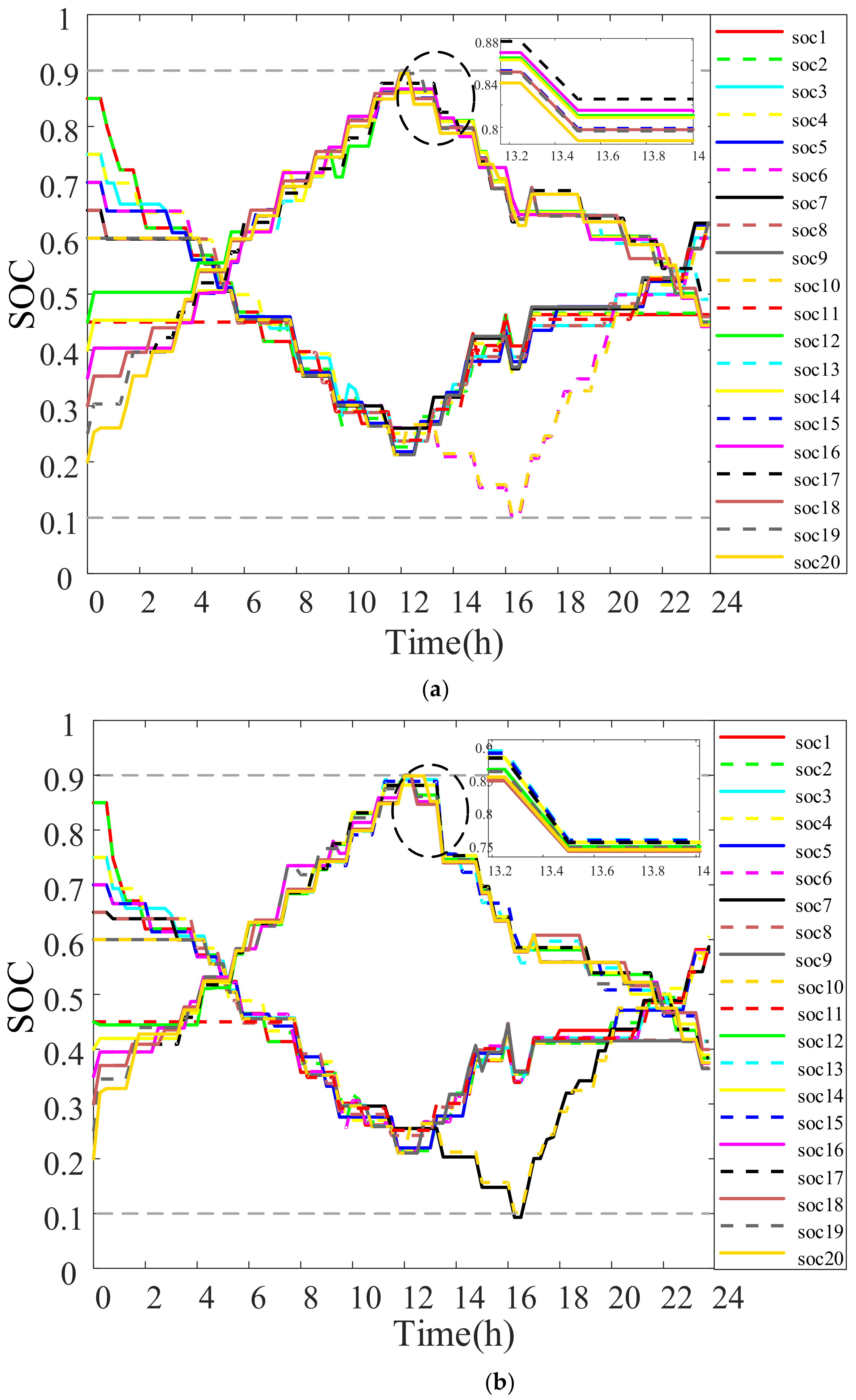
Aiming at the power distribution between the started units, an SOC consistency algorithm based on multi-agent was used. Compared with the power distribution mode of power average distribution, the SOC values among energy storage units tend to be more consistent in the scheduling period.
However, the control strategy in this paper only considered the energy storage unit’s life and the balance of SOC, and the economic benefits of the wind–solar energy storage microgrid operation were not considered. In the future, this will be improved by combining the benefits of the scheduling plan. The total operating cost, energy storage unit loss, and SOC consistency of the energy storage power station will be comprehensively considered to further promote the economy of wind–solar energy storage system operation.

Author Contributions

Methodology, W.G.; writing—original draft, X.G. and W.F.; writing—review and editing, Y.Z. and J.A.; formal analysis, C.H. and Y.Q.; data curation, L.M. and H.Z. All authors have read and agreed to the published version of the manuscript.

Funding

This work is supported by a project of the State Grid Hebei Economic Research Institute (SGHEJY00GHJS2200055).

Data Availability Statement

Not applicable.

Conflicts of Interest

The authors declare no conflict of interest.

Nomenclature

AbbreviationMeaningUnits
P b Power command of the battery energy storage power stationMW
P g Scheduling instructionMW
P w The output power of wind turbinesMW
P v The output power of photovoltaic arraysMW
P g Scheduling instructionMW
T d Scheduling intervalh
E Remaining capacity of the energy storage unit MW · h
E N Rated capacity of the energy storage unit MW · h
P b i The output power of the i th energy storage unitMW
η b c Charging efficiency of the energy storage unit-
η b d Discharging efficiency of the energy storage unit-
m The number of starting energy storage units-
μ Weight parameter-
d Starting identifier-
a i j Connection relationship between the i th energy storage unit and the j th energy storage unit-
P m Rated discharge power of the energy storage unitMW
W State transition identifier-
P N Rated discharge power of the charging and discharging groupMW
N b The number of energy storage units in the charging and discharging group-
S O C m i n The minimum SOC of a single energy storage unit-
S O C m a x The maximum SOC of a single energy storage unit-
δ The ratio of the charging group and discharging groupMW/MW
N The number of energy storage units -
i , j Battery energy storage unit number-

References

  1. Li, X.; Lyu, L.; Geng, G.; Jiang, Q.; Zhao, Y.; Ma, F.; Jin, M. Power allocation strategy for battery energy storage system based on cluster switching. IEEE Trans. Ind. Electron. 2022, 69, 3700–3710. [Google Scholar] [CrossRef]
  2. Yu, Y.; Chen, D.Y.; Wu, Y.W.; Li, J.L.; Wang, B.X. Power allocation strategy considering SOC balance and income for battery energy storage in smoothing wind power fluctuations. High Volt. Eng. 2022, 8, 86. [Google Scholar] [CrossRef]
  3. Yan, G.G.; Cai, C.X.; Duan, S.M.; Li, H.B.; Liu, Y.; Li, J.H. Operation control strategy of microgrid considering grouping optimization of battery energy storage units. Autom. Electr. Power Syst. 2020, 44, 38–46. [Google Scholar]
  4. Guo, W.; Zhao, H.S. Grouping control strategy of battery energy storage array based on DMPC weighted consensus algorithm. Electr. Power Autom. Equip. 2020, 40, 133–140. [Google Scholar]
  5. Zhao, Y.; Shi, X.W.; Wang, L.B.; Liu, H.M.; Yang, J.F. Power allocation strategy of large-scaled battery energy storage power station. Power Syst. Technol. 2022, 46, 5004–5012. [Google Scholar]
  6. Zou, J.; Shu, J.; Zhang, Z.; Luo, W. An Active power allocation method for wind-solar-batteries hybrid power system. Electr. Mach. Power Syst. 2014, 42, 1530–1540. [Google Scholar] [CrossRef]
  7. Li, X.; Ma, R.; Yan, N.; Wang, S.; Hui, D. Research on Optimal Scheduling Method of Hybrid Energy Storage System Considering Health State of Echelon-Use Lithium-Ion Battery. IEEE Trans. Appl. Supercond. 2021, 31, 0604204. [Google Scholar] [CrossRef]
  8. Li, G.; Yang, Z.; Li, B.; Bi, H. Power allocation smoothing strategy for hybrid energy storage system based on Markov decision process. Appl. Energy 2019, 241, 152–163. [Google Scholar] [CrossRef]
  9. Fu, H.; Lu, P.; Zhang, J.N. Allocation Strategy of DC Microgrid All Vanadium Redox Flow Battery Energy Storage System Based on A-SA-WOA Algorithm. Trans. China Electrotech. Soc. 2023. [Google Scholar] [CrossRef]
  10. Li, D.; Wu, Z.; Zhao, B.; Zhang, L. An Improved Droop Control for Balancing State of Charge of Battery Energy Storage Systems in AC Microgrid. IEEE Access 2020, 8, 71917–71929. [Google Scholar] [CrossRef]
  11. Wang, W.X.; Duan, J.D.; Zhang, R.S.; Guo, H. Optimal state-of-charge balancing control for paralleled battery energy storage devices in islanded microgrid. Trans. China Electrotech. Soc. 2015, 30, 126–135. [Google Scholar]
  12. Kakigana, H.; Miura, Y.; Ise, T. Distribution voltage control for DC microgrids using fuzzy control and gain scheduling technique. IEEE Trans. Power Electron. 2013, 28, 2246–2258. [Google Scholar] [CrossRef]
  13. Li, C.D.; Coelho, E.A.; Dragicevi, T.; Guerrero, J.M.; Vasquez, J.C. Multiagentbased distributed state of charge balancing control for distributed energy storage units in AC microgrids. IEEE Trans. Ind. Appl. 2017, 53, 2369–2381. [Google Scholar] [CrossRef]
  14. Jiang, Q.Y.; Gong, Y.Z.; Wang, H.J. A battery energy storage system dual-layer control strategy for mitigating wind farm fluctuations. IEEE Trans. Power Syst. 2013, 18, 3263–3273. [Google Scholar] [CrossRef]
  15. Tan, S.C.; Zhang, H.; Xiao, X.; Zhi, N. A power sharing method based on SOC unbalanced degree for energy storage. Power Electron. 2016, 50, 57–59. [Google Scholar]
  16. Nguyen, C.L.; Lee, H.H. A novel dual-battery energy storage system for wind power applications. IEEE Trans. Ind. Electron. 2016, 63, 6136–6147. [Google Scholar] [CrossRef]
  17. Lin, L.; Jia, Y.; Ma, M.; Jin, X.; Zhu, L.; Luo, H. Long-term stable operation control method of dual-battery energy storage system for smoothing wind power fluctuations. Int. J. Electr. Power Energy Syst. 2021, 129, 106878. [Google Scholar] [CrossRef]
  18. Long, B.J.; Zhang, J.; He, Y.; Cheng, R.; Fan, L.; Li, B.; Gu, T.; Fu, X.; Li, H. Grouping consistency control strategy based on DMPC and energy storage unit constraints. Power Syst. Prot. Control 2022, 50, 23–36. [Google Scholar]
  19. Yu, Y.; Chen, D.Y.; Wang, B.X.; Wu, Y.W.; Lu, W.T.; Mi, Z.Q. Control scheme to extend lifetime of BESS for assisting wind farm to track power generation plan based on wind power feature extraction. IET Power Electron. 2022, 15, 1629–1651. [Google Scholar] [CrossRef]
  20. Zhao, H.S.; Guo, W. Hierarchical Distributed Coordinated Control Strategy for Hybrid Energy Storage Array System. IEEE Access 2018, 7, 2364–2375. [Google Scholar] [CrossRef]
  21. Guo, W.; Zhao, H.S. Grouping Control Strategy of Battery Energy Storage Array System Based on an Improved Distributed Consensus Algorithm. Trans. China Electrotech. Soc. 2019, 34, 4991–5000. [Google Scholar]
  22. Yu, Y.; Chen, D.Y.; Wu, Y.W.; Wang, B.X.; Cai, X.L.; Dong, K. Grouping control strategy of battery energy storage for reducing life loss under wind power tracking scheduling plan. Electr. Power Autom. Equip. 2022, 9, 16. [Google Scholar] [CrossRef]
  23. Yang, T.; Yu, M.; Fang, F. State-of-charge balancing control for battery energy storage system based on event-triggered scheme. Appl. Phys. A Mater. Sci. Process. 2019, 125, 339. [Google Scholar] [CrossRef]
  24. Qi, D.; Hu, J.H.; Liang, X.L.; Zhang, J.Q.; Zhang, Z.H. Research on consensus of multi-agent systems with and without input saturation constraints. J. Syst. Eng. Electron. 2021, 32, 947–955. [Google Scholar]
  25. Trejo, J.; Rotondo, D.; Medina, M.A.; Trejo, J.A.V.; Beltrán, C.D.G.; Morales, J.G. Robust Observer-based Leader-Following Consensus for Multi-agent Systems. IEEE Lat. Am. Trans. 2021, 19, 1949–1958. [Google Scholar] [CrossRef]
  26. Wang, B.; Cai, G.; Yang, D. Dispatching of a Wind Farm Incorporated with Dual-Battery Energy Storage System Using Model Predictive Control. IEEE Access 2020, 8, 144442–144452. [Google Scholar] [CrossRef]
  27. Li, X.J.; Hui, D.; Lai, X.K. Battery Energy Storage Station (BESS)-Based Smoothing Control of Photovoltaic (PV) and Wind Power Generation Fluctuations. IEEE Trans. Sustain. Energy 2013, 4, 464–473. [Google Scholar] [CrossRef]
  28. Tankari, M.A.; Camara, M.B.; Dakyo, B.; Lefebvre, G. Use of ultracapacitors and batteries for efficient energy management in wind-diesel hybrid system. IEEE Trans. Sustain. Energy 2013, 4, 414–424. [Google Scholar] [CrossRef]
  29. Yan, G.G.; Zhu, X.X.; Li, J.W.; Mu, G.; Luo, W.H. Control Strategy Design for Hybrid Energy Storage System with Intrinsic Operation Life Measurement and Calculation. Autom. Electr. Power Syst. 2013, 37, 110–114. [Google Scholar]
  30. Lou, S.H.; Yi, L.; Wu, Y.W.; Hou, T. Optimizing Deployment of Battery Energy Storage Based on Lifetime Predication. Trans. China Electrotech. 2015, 30, 265–271. [Google Scholar]
Figure 1. Wind–solar energy storage system structure.
Energies 16 01857 g001
Figure 2. Flow chart of power distribution.
Energies 16 01857 g002
Figure 3. Wind–solar power and scheduling instruction curve.
Energies 16 01857 g003
Figure 4. Energy storage power curve.
Energies 16 01857 g004
Figure 5. Cumulative probability distribution of energy storage power. (a) Cumulative probability distribution of charging power of energy storage; (b) Cumulative probability distribution of discharging power of energy storage.
Energies 16 01857 g005
Figure 6. Power command and actual response curve.
Energies 16 01857 g006
Figure 7. Power curves of charge and discharge groups.
Energies 16 01857 g007
Figure 8. SOC variation curve of each energy storage unit. (a) Average power distribution; (b) Multi-agent SOC consistency.
Energies 16 01857 g008
Figure 9. Daily equivalent cycle times of each energy storage unit.
Energies 16 01857 g009
Table 1. Battery energy storage power station parameters.
ParameterValues
Number of energy storage units20
Rated capacity of energy storage unit/(MW·h)1.2
Rated power of energy storage unit/MW0.3
Efficiency of charging and discharging (%)90
S O C m a x / S O C m i n 0.9/0.1
Table 2. Initial SOC of battery energy storage unit.
Unit NumberInitial SOCUnit NumberInitial SOC
No.10.85No.110.45
No.20.85No.120.45
No.30.75No.130.4
No.40.75No.140.4
No.50.7No.150.35
No.60.7No.160.35
No.70.65No.170.3
No.80.65No.180.3
No.90.6No.190.25
No.100.6No.200.2
Disclaimer/Publisher’s Note: The statements, opinions and data contained in all publications are solely those of the individual author(s) and contributor(s) and not of MDPI and/or the editor(s). MDPI and/or the editor(s) disclaim responsibility for any injury to people or property resulting from any ideas, methods, instructions or products referred to in the content.

