Article

Analysis of Losses in Two Different Control Approaches for S-S Wireless Power Transfer Systems for Electric Vehicle

1
Department of Industrial Engineering, University of Padova, 35131 Padua, Italy
2
Tata Consultancy Services, Bangalore 560066, India
*
Authors to whom correspondence should be addressed.
Energies 2023, 16(4), 1795; https://doi.org/10.3390/en16041795
Submission received: 15 January 2023 / Revised: 7 February 2023 / Accepted: 9 February 2023 / Published: 11 February 2023

Abstract

:
This paper presents the study and detailed analysis of converter losses at different stages together with the series-series (S-S) compensating coils in wireless power transfer (WPT) systems, via two distinct approaches to control the power converters. The two approaches towards wireless DC–DC power flow control are termed as the Single Active High-Frequency Wireless Power Transfer (SAHFWPT) system and the Dual Active High-Frequency Wireless Power Transfer (DAHFWPT) system. The operation of converters in SAHFWPT and DAHFWPT are controlled by the extended phase shift (EPS) and dual phase shift method respectively. The general schematic of the SAHFWPT system consists of an active bridge and a passive bridge, while the schematic of the DAHFWPT system consists of both active bridges. The efficiency evolutions of ideal SAHFWPT and DAHFWPT are far away from the real ones. Moreover, this article analyzes the operation and losses of the uni-directional power flow of the WPT system, i.e., from the DC bus in the primary side to the battery load in the secondary side. The loss estimation includes high-frequency switching losses, conduction losses, hard turn on and turn off coil losses, etc. Moreover, the efficiency of the WPT system depends on operation of the converter. A 50 W–3600 W Power range system at a resonant frequency of 85 kHz is implemented in MATLAB/SIMULATION to demonstrate the validity of the proposed method.

1. Introduction

The typical wireless power transfer (WPT) systems have several ranges in terms of power ratings, from a few watts to kilowatts, depending on the applications, such as portable electrical devices, medical devices (Pacemaker), mechanical instruments, and transportation (electrical vehicles (EVs)) in [1,2].
In the current scenario, the energy storage system (ESS) plays an important role during the different trend of power demand as explained in [3]. As intensity of renewable energy (RE) is not constant throughout a day, the ESS plays a crucial role in the area of storage excess energy that can be generated by the RE sources [4], and that can be used to power the various loads such as a household load, industrial load, street load, etc. when we are not able to use the RE sources. The wireless DC–DC converters are becoming more pervasive due to the fact that they are compact in size, isolated power flow between the resonating coils, and have excellent efficiency. In earlier studies, there have been a lot of isolated DC–DC power converters, such as single active bridge (SAB), dual active bridge (DAB), phase shift full bridge (PSFB), and so on for high-frequency applications mentioned in [5,6,7,8].
Figure 1 shows the generalized schematic of the wireless DC–DC converter that can be used for both Single Active High-Frequency Wireless Power Transfer (SAHFWPT) and Dual Active High-Frequency Wireless Power Transfer (DAHFWPT). During the operation of the SAHFWPT system, the primary side converter operates as an active converter, i.e., high-frequency inverter, and the secondary side converter operates as a passive converter through the diode, i.e., uncontrolled rectifier. The control approach of the primary H-bridge converter takes place by the internal phase shift control method as describe in [9,10,11]. In the operation of DAHFWPT system, the primary and secondary sides H-bridge converters are operating as active bridges, but their operation is different, i.e., the primary works as the high-frequency inverter and the secondary works as the controlled rectifier [12]. Moreover, the control of the primary and secondary H-bridge converters was also takes place by the internal phase shift control method. However, in both the SAHFWPT and DAHFWPT converters, power transfer takes place via external phase shift of converter from the source voltage V S to the load which can be considered equivalent load resistance R B in place of the battery. As the H-bridge works at high frequency, the passive components (i.e., S-S coupling coil, source filters, and load filters) compatibly reduce in size so that the SAHFWPT and DAHFWPT system stand out due to the high values for the power density as well as specific power in [13,14,15,16].
As previously stated, the SAHFWPT and the DAHFWPT converters can be used in applications requiring both uni-directional and Bi-directional power flow, such as electric vehicles, household appliances, mobile phones, medical devices, and other fields [17]. The schematics for SAHFWPT and DAHFWPT in Figure 1 include two H-Bridge, besides the two H-bridges, with following elements: (1) the coupling coils L P and L S as well as the series resonating capacitors C P and C S , which keep coil current sinusoidal even when the voltage across the series compensated coil in a quasi-square or square wave; the mutual inductance M between the primary and secondary coils; (2) the capacitor C O , which filters out ripple of the voltage V O ; (3) the inductor L O , which can filter out the ripple of current that passes through R B ; (4) and the resistance R B represents the battery’s equivalent resistance [18,19,20,21,22,23,24].
The most effective optimization models are those that are based on the nonlinear equivalent model of the magnetic equivalent coupler of the WPT converters. This model considers the losses that are incurred as a result of the nonlinear operation of the converters, which include the conduction losses in MOSFETs, diodes, and body diodes, the hard-switching loss of the switches, and the reverse recovery loss of diodes. The gap between standard loss models and experimental measurements is well-known in [6]. Table 1 provides a comparison overview between a SAHFWPT and a DAHFWPT in terms of control method, losses, and selection of extra DC–DC converter. It is ideal to build a DAHFWPT battery charger with no additional DC–DC converter. Soft switching of the inverter and active rectifier circuits takes place with the help of zero voltage switching (ZVS) and zero current switching (ZCS), resulting in low circulating reactive power when the external phase shift of the converters is equal to 3π/2, and optimized overall loss is described in [14]. Depending on their application, four distinct switching modes (single phase shift (SPS) [25], extended phase shift (EPS), dual phase shift (DPS) [26], and triple phase shift (TPS) [6] may be used to optimize converters losses. Whereas, SAHFWPT is ideal to build a battery charger with an additional DC–DC converter, while SAHFWPT has no circulating current as the external phase shift angle is fixed at 3π/2, soft switching of the inverter and passive rectifier by the help of zero voltage switching (ZVS) and zero current switching (ZCS) are mention in [27], and overall loss optimization. Depending on their use, two distinct switching options are available, such as SPS and EPS. The S-S coil losses are included in both systems, but these losses are not same as they are dependent on the current and design parameters of the coil.
Many of the articles discuss the switching operation, power flow operation, and different approaches to control of the SAHFWPT and DAHFWPT converters for EV. The comparative study of power loss of converters and coils during operation of the SAHFWPT and DAHFWPT converters is discussed in this article. Apart from that, the purpose of this paper is to study the effects on the overall efficiency of the WPT of the two different control methods, i.e., EPS and DPS of the H-bridge converter for SAHFWPT and DAHFWPT, respectively. Further, we performed a comparative analysis of the power range of WPT, while keeping the battery voltage constant. For this study, we fixed the internal phase angle of the primary and secondary H-bridge, the angles to be equal in the operation of DAHFWPT, and we are aware that the secondary of SAHFWPT works as the uncontrolled rectifier. So, to maintain the same power drawn from the source as DAHFWPT, we must only change the internal phase shift angle of the primary H-bridge.
Here is how the rest of the article is put together: In Section 2, we provide a quick overview of the SAHFWPT and DAHFWPT, as well as how the switching of converter takes place at 85 kHz based on the SAE J2954 standard. Besides that, there is a comparison of secondary power. In Section 3, we briefly discuss the loss study at different stages of the converters. In Section 4, we compare the efficiency of the coupling coil of both systems. In Section 5 we report the result, the SAHFWPT and DAHFWPT are tested based on their total loss, and their maximum rated input power for a given power, the behavior of the current, and voltage in the primary and secondary the system efficiency. The paper concludes in Section 6.

2. Methods of Operation of SAHFWPT and DAHFWPT

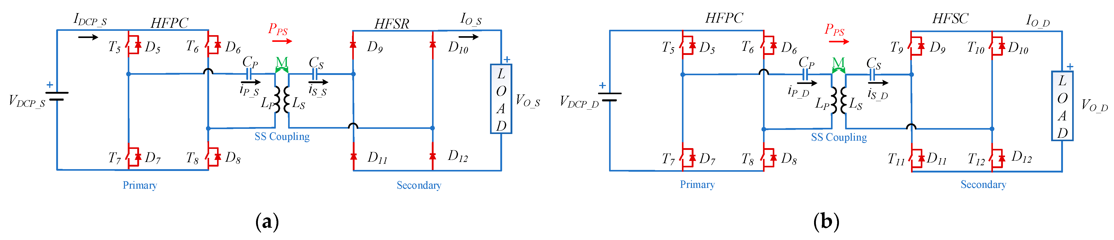
2.1. Circuit Schematic

The schematics of the SAHFWPT and DAHFWPT converters are shown in Figure 2a,b. The SAHFWPT and DAHFWPT are separated into primary and secondary sections. The primary active H-bridge is designed as the high-frequency primary converter (HFPC), which is powered by the DC source voltages V D C P _ S and V D C P _ D for both the SAHFWPT and the DAHFWPT, respectively. HFPC work as a high-frequency phase shift inverter, generating high-frequency quasi-square wave output voltages v H F P C _ S and v H F P C _ D . The output current i P _ S and i P _ D are sinusoidal due to the resonating effect of the coil. Moreover, output voltage waveform level depends on switching control method, as mentioned in Table 1. The output voltage levels of HFPC by SPS and EPS switching are two and three, whereas in the control operation the HFSC have an output voltage level of two in SAHFWPT and DAHFWPT. Aside from these two switching methods, the DPS and TPS are only useful for DAHFWPT. Since the SAHFWPT secondary is uncontrolled and the resulting voltage is always two levels. The HFPC consists of four MOSFETs ( T 5 T 8 ). Furthermore, if we look at the HFPC schematic in Figure 2a,b, we can observe the antiparallel body diodes ( D 5 D 8 ) of MOSFETs, that can be operated when the circulating current flow takes place. The coupled coils create the connection between the primary and secondary converter by wireless means. The secondary H-bridges is referred as the high-frequency secondary rectifier (HFSR) or high-frequency secondary converter (HFSC) according to their passive or active operations, respectively. The voltage v H F S R _ S and v H F S C _ D induced in the secondary coil due to variation in current i P _ S and i P _ D in the primary coil, according to the Faraday law of induction, secondary voltage serves as the input voltage source of the HFSR and HFSC and the current i S _ S and i S _ D flow through the secondary coil. The output voltage V O _ S and V O _ D of the HFSR and HFSC are applied across the equivalent load, which includes the low pass filter L O C O and R B equivalent battery resistance, where C O can be used to smooth or remove the ripple of voltage V O _ S and V O _ D , and L O can be used to smooth or remove ripple of current I O _ S and I O _ D . The output voltages V O _ S and V O _ D , as well as the currents I O _ S and I O _ D , are kept at the desire levels for charging the battery by the phase-shifted regulation of the HFPC and HFSC. The HFSR and HFSC are fabricated of four high-frequency diodes ( D 9 D 12 ) and MOSFETs ( T 9 T 12 ) with the relevant antiparallel body diodes ( D 9 D 12 ), respectively. The primary side’s input filter is a C I filter, which is not seen in Figure 2a,b.
The switching frequency of the SAHFWPT and DAHFWPT converters are in the range of 79–90 kHz. The operating frequency was fixed at 85 kHz and the resonant circuits are tuned to this frequency as in [9,10]. This frequency is selected as per the J2954 standard of the society of automotive engineering (SAE) about charging of electric vehicle through WPT. The design of self-inductor L P , L S and capacitors C P , C S of the series-series resonating coil are usually at resonating frequency ω r i.e,
ω r = 1   L P C P = 1 L S C S

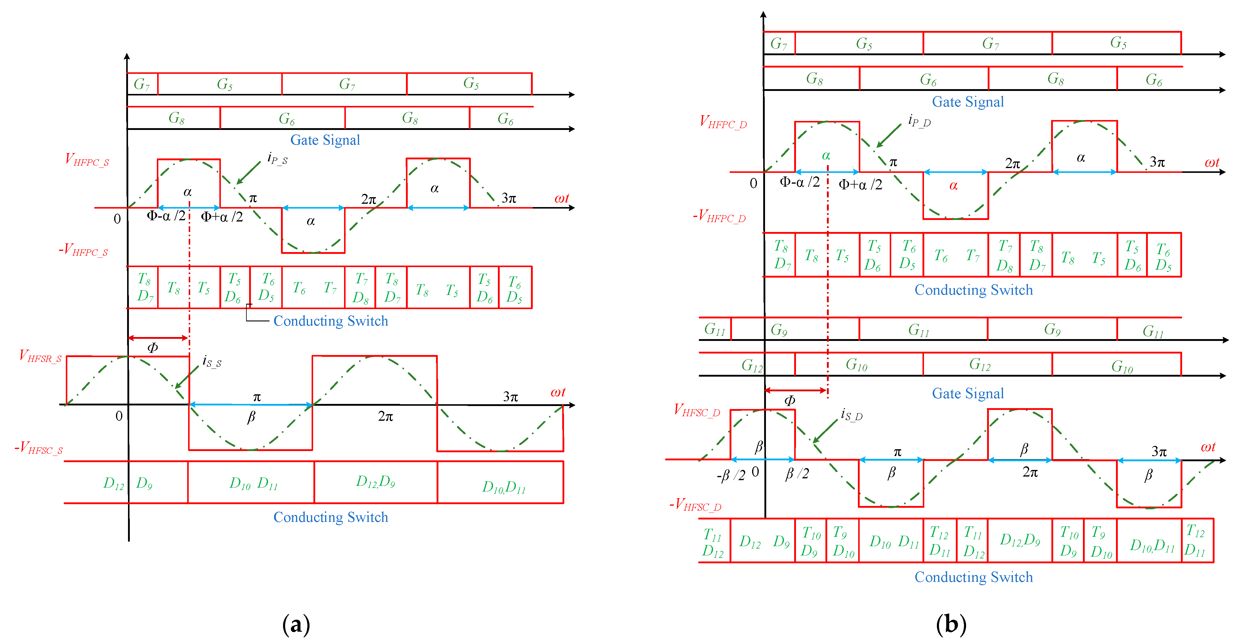
2.2. Operation and Analysis

Figure 3a,b depict the switching operation of the SAHFWPT and DAHFWPT converters at resonance frequency. The EPS and DPS switching mechanisms are used to control the converters of SAHFWPT and DAHFWPT, respectively. The plot is divided in three parts: (1) gate signals of the HFPC on the upper section of the plot, (2) waveforms of current and voltage of HFPC together with the conduction intervals of its switches, (3) and waveforms of current and voltage for HFSR together with the conduction intervals of its switches in the case of SAHFWPT (Figure 3a) and gate signals. For correlation between both the wave forms, the gate signals in the upper section are assumed same for both SAHFWPT and DAHFWPT, the HFPC switching operation takes place by the internal phase shift angle between its two legs. The middle part of Figure 3a,b, depicts the direction of current flow through the HFPC’s. During the positive half cycle of the current, three different switching periods can be recognized, namely (1) interval 1: (0 to Φ − α/2), (2) interval 2: (Φ − α/2 to Φ + α/2), and (3) interval 3: (Φ + α/2 to π). While the currents i P _ S and i P _ D circulate in the MOSFETs and body diode, the circulating current does not flow across the source voltage V D C P _ S and V D C P _ D , respectively. Indeed, the output voltage of HFPC is zero, i.e., v H F P C _ S   =   v H F P C _ D = 0 , in the intervals 1 and 3. Switches (T8, D7), and (T5, D6) are in conduction state, as the energy stored in the reactive element such as L P and C P forces the current to circulate in intervals 1 and 3. Aside from that, the amplitudes of v H F P C _ S and v H F P C _ D in interval 2 are identical to V D C P _ S and V D C P _ D . The wave forms clearly show that the output voltages v H F P C _ S and v H F P C _ D square, as well as the currents current i P _ S and i P _ D sinosuidal, are in the same phase and have half-wave symmetry, due to the resonating behavior of the coil. As per the Faraday law induction, EMF is induced in the secondary coil due to flux linkage between the primary and secondary. The average power P P S flow from primary to secondary due to induced voltage in the secondary, which can serve as voltage source for the SAHFWPT and DAHFWPT secondary.
HFSR and HFSC converters are passive and active in behavior, respectively. As shown in the lower part of the waveform in Figure 3a, HFSR conducts for a full cycle, i.e., ( D 12 , D 9 ) conducts during the positive half cycle and ( D 10 , D 11 ) conducts during the negative half cycle. As a matter of fact, the HFSR input voltage v H F S R _ S and current i S _ S are square and sin wave, respectively, thanks to the resonating behavior of the coil. On the contrary, the active rectifier HFSC operation during the positive half cycle is divided into three intervals: (1) interval 1: −π/2 to −β/2; (2) interval 2: −β/2 to β/2; and (3) interval 3: β/2 to π/2). In the intervals 1 and 3, the output voltage of HFSC is zero, i.e., v H F S C _ D   = 0, while the current i S _ D flows in the MOSFETs and body diodes of HFSC and do not reach the load. The switches T 11 , D 12 and T 10 , D 9 are in conduction state during the intervals 1 and 3 respectively. The circulation of current occurs due to the energy stored in the reactive elements such as C S and L S . Apart from this, the amplitudes of v H F S R _ S and v H F S C _ D are equal to V O _ S and V O _ D in the interval 2. From the shape of the wave form, it was easy to see that the output voltages v H F S R _ S and v H F S C _ D square and the currents i S _ S and i S _ D sinusoidal have the same phase and are half-wave symmetric, due to the resonating behavior of the coil.
The output voltages V O _ S , V O _ D and currents i S _ S , i S _ D of the HFSR, and HFSC are almost constant due to filtering effect of L O and C O . The external phase shift angle for primary and secondary converter is fixed at Φ in the case of SAHFWPT and DAHFWPT.
The equivalent circuit of SAHFWPT and DAHFWPT with S-S coupling is shown in Figure 4. As per Figure 3 the operation begins at time t = 0, and the internal phase shift angles of HFPC and HFSC are α and β, respectively (whereas in the case of SAHFWPT, β = π is fixed). The external phase shift angle Φ varying in the range [0 2π] during the operation of DAHFWPT (whereas Φ = 3π/2 is fixed in the case of SAHFWPT). The voltages v H F P C and v H F S C are expressed as a Fourier series as follows:
v H F P C t = v H F P C _ M n = 1 ,   3 , 1 n sin ω r t sin n α 2
v H F S C t = v H F S C _ M n = 1 ,   3 , 1 n sin ω r t + Φ sin n β 2
The maximum values of amplitudes for the first harmonic components of the voltages of the HFPC and HFSC of DAHFWPT are represented by v H F P C _ M and v H F S C _ M , respectively. Take into consideration that the external phase shift angle Φ ranges in the interval [0, 2π] for the Bi-directional operation DAHFWPT, whilst for the uni-directional operation, such as power flow exclusively from primary to secondary, the external phase shift angle Φ spans the interval [π, 2π]. However, for maximum power transfer it is Φ = 3π/2. Apart from Φ = 3π/2 value, the power transfer is not maximal due to the reactive current being not in the phase with the HFPC output and HFSC input voltage. This leads the circulating current flowing through the converter and coil.
Since the HFSR is a passive converter, the following conditions hold β = π and Φ = 3π/2, and from (3) the input voltage for the HFSR is expressed as:
v H F S R t = v H F S R _ M n = 1 ,   3 , 1 n sin ω r t + Φ
The harmonic and maximum harmonic input voltage of HFSR of SAHFWPT are represented by v H F S R and v H F S R _ M . From Equation (2) it is clear that primary voltage v H F P C relation is same for SAHFWPT and DAHFWPT. So from Figure 3 and Figure 4  v H F P C _ S = v H F P C _ D = v H F P C . Indeed the secondary voltage relation is not same, from the Figure 3 and Figure 4, v H F S R _ S = v H F S R and v H F S C _ D = v H F S C , respectively.
Applying Kirchhoff’s voltage law in Figure 4, we obtain
v H F P C t = R P i P t + L P d i P t d t + v P C t + v P t
v H F S C t = R S i S t + + L S d i s t d t + v s C t + v S t
where R P and R S internal resistance,   L P and L s self-impedance of coil, v P C t and v S C t voltage drop across capacitor, i P t and i S t current flow from the S-S coil, v P t = M d i S t d t and v S t = −M d i P t d t are the induced voltage of primary and secondary S-S coils, respectively, M is the mutual inductance.
At the resonance frequency, the instantaneous power absorbed by the inductor L P , L S is equal to the instantaneous power delivered by the capacitor C P , C S . The net power delivered and absorbed by the capacitor and inductor is zero in the primary and secondary S-S coils, respectively. The impedance of the S-S coils is minimum at the resonating condition. Indeed, primary and secondary coil impedances are minimum; therefore, they represent the internal resistance of the S-S coil, i.e., R P ,   R S . Therefore, Equations (5) and (6) are re-arranged at resonating frequency as
i P t = v H F P C t v P t R P
i S t = v H F S C t + v S t R S
The voltage and current relationship at fundamental resonance frequency are represented in (8) to (11) for the DAHFWPT, similarly it is represented in (12) to (15) for SAHFWPT, by using approximation ω M > > R S and ω M 2 > > R P R S for high Q-factor coil [6]. The expressions DAHFWPT and SAHFWPT are represented at fundamental harmonic approximation of the sinusoidal component in Table 2 and Table 3 [20,22], respectively.
v H F P C _ 1 _ M , v H F S C _ 1 _ M and v H F P C _ 1 , v H F S C _ 1 are the fundamental maximum amplitude and fundamental voltage of HFPC and HFSC, respectively. The secondary fundamental currents i s _ 1 , represented in Equations (11) and (15) for DAHFWPT and SAHFWPT, are the same as they only depend on α . Moreover, the primary fundamental current i P _ D _ 1 of DAHFWPT depends on β , while the primary fundamental current i P _ S _ 1 of SAHFWPT is constant, as β is fixed at π.
The uni-directional power flow was considered only in the case of battery charging, and the rated source voltages V D C P _ S = V D C P _ D = 386 V are constant for SAHFWPT and DAHFWPT; as mentioned in Table 4 the battery voltage is also same, i.e., V O _ S =   V O _ D = 120 V. The secondary absolute lossless power for SAHFWPT and DAHFWPT can be express in (16) and (17) by using the (9), (11), (13), and (15)
P S A H F W P T _ S = v H F P C _ 1 _ M v H F S C _ 1 _ M sin α 2 sin Φ 2 ω M
P D A H F W P T _ S = v H F P C _ 1 _ M v H F S C _ 1 _ M sin α 2 sin β 2 sin Φ 2 ω M
where v H F P C _ 1 _ M = 4 V D C P _ S π and v H F S R _ 1 _ M = 4 V O π are the maximum voltage at the primary and secondary coil. From the Equations (16) and (17), the secondary power can be regulated using the internal phase shift angles α = β ∈ [0, 2π], and external phase shift angle Φ ∈ [π, 2π], while in Equation (16) β = π and Φ = 3π/2. the secondary power of SAHFWPT and DAHFWPT can be related by Equation (18):
P D A H F W P T _ S = sin β 2 P S A H F W P T _ S
Figure 5 shows the comparison of power curve between DAHFWPT and SAHFWPT of secondary power, w.r.t α, where α is in radian. The power P D A H F W P T _ S plotted with the red line, and P S A H F W P T _ S plotted with the blue line are directly related with sin(α/2) as mentioned in (18), when we fixed Φ = 3π/2 for maximum power transfer condition. From the power curve, it can be proven that the power of DAHFWPT and SAHFWPT are same at α = 3.14, i.e., π. Apart from that, DAHFWPT power sinusoidal decreases and it is always less than the SAHFWPT power that decreases almost linearly. It is observed in Figure 5 that SAHFWPT and DAHFWPT have similar instantaneous power, the internal phase shift angle of secondary power of DAHFWPT is always bigger than secondary power of SAHFWPT.

3. Methods of Loss Analysis of SAHFWPT and DAHFWPT
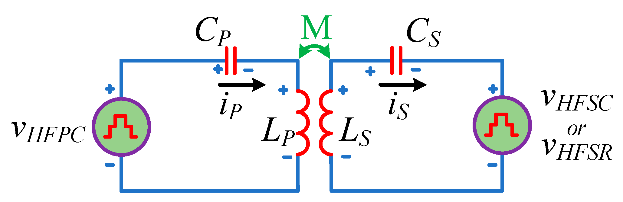
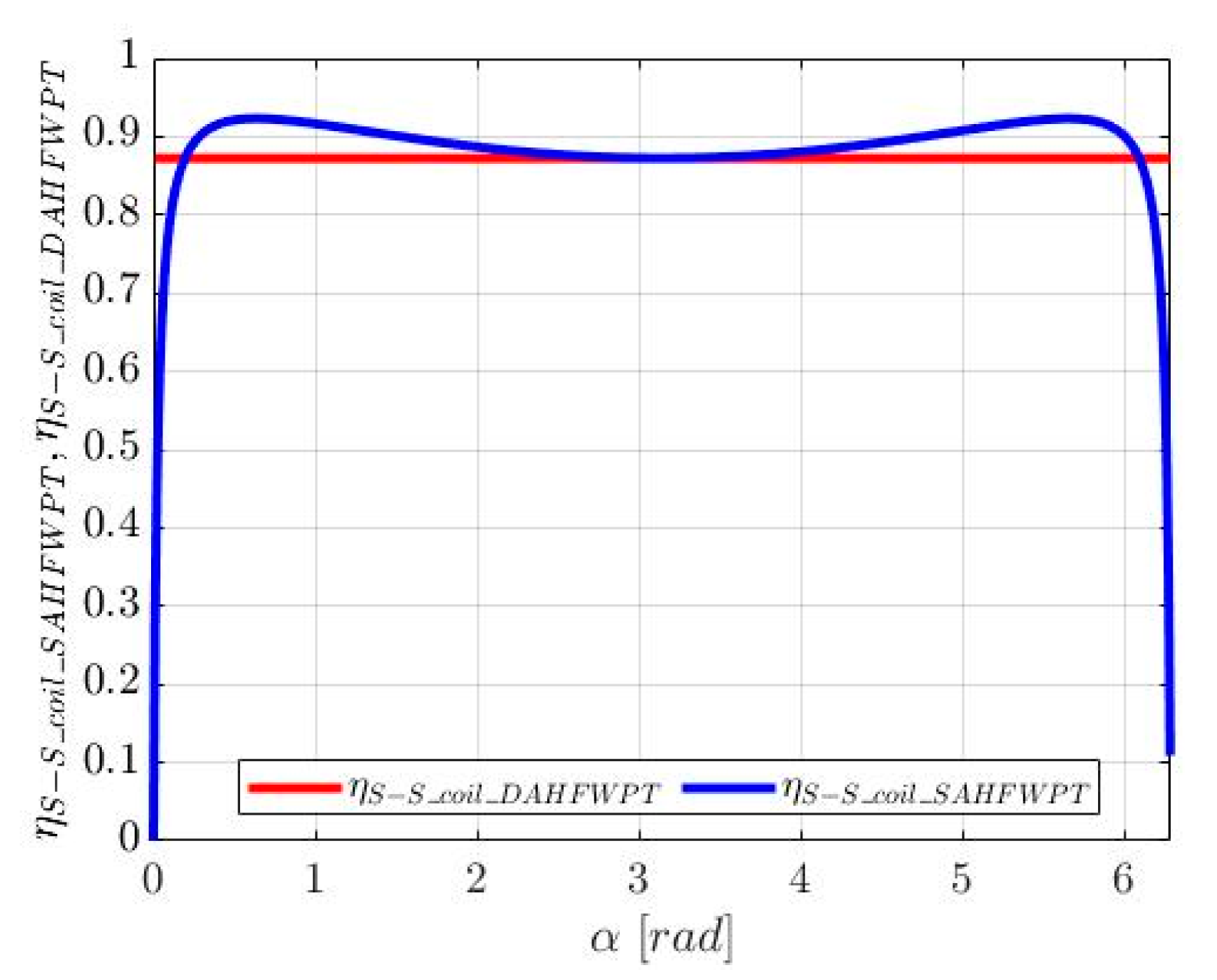
The operation of SAHFWPT and DAHFWPT are approximately same. The only difference is in the operation of the secondary side converter. The secondary HFSR of SAHFWPT is the passive converter, while the secondary HFSC of DAHFWPT is the active converter. Because HFSR and HFSC work in different ways, they are operating in the soft switching mode and the hard switching mode, respectively. Indeed, the switching losses of switches for the HFSR and HFSC are lower and higher, respectively. However, each diode of the HFSR are conducted for a π phase interval, whereas the conducting phase interval of the HFSC switches depending on β which one varies in the range of [0, 2π] so that the conduction period of HFSC switches may be π or the lesser than π period. The conduction loss of MOSFETs and body diodes depends on the amount of current flowing in the converter. As the secondary converter operation of the SAHFWPT and DAHFWPT are not the same, the power drawn from the source towards the rated load is different. Furthermore, conduction losses are only equal at the α = β = π. Apart from this loss, the few losses that depend on the converters are due to the gate charge, body diode conduction, output capacitor, body diode recovery, hard turn on, and hard turn off. In this section the comparative loss in the S-S coil is elaborated by using simulation parameter that listed in Table 4 whilst the losses in the filter capacitor and inductor are neglected.

3.1. S-S Coil Loss

Referring to the equivalent circuit shown in Figure 4, the resistive loss of the S-S coupling coil [10] can be expressed as:
P S S _ c o i l _ S A H F W P T _ l o s s =   i P _ S _ 1 _ r m s 2 R P + i S _ 1 _ r m s 2 R S
P S S _ c o i l _ D A H F W P T _ l o s s =   i P _ D _ 1 _ r m s 2 R P + i S _ 1 _ r m s 2 R S
where i P _ S _ 1 _ r m s , i P _ D _ 1 _ r m s , and i S _ 1 _ r m s are the rms values of i P _ S _ 1 , i P _ D _ 1 , and i S _ 1 , respectively. R P and R S are the primary and secondary coil resistance. Using (10), (14) and any one from (11) and (15), we obtain
i P _ S _ 1 _ r m s = v H F S R _ 1 _ M 2 M ω r
i P _ D _ 1 _ r m s = v H F S C _ 1 _ M 2 M ω r sin β 2
i S _ 1 _ r m s = v H F P C _ 1 _ M 2 M ω r sin α 2
The efficiency of the S-S coupling coil of SAHFWPT and DAHFWPT can be expressed by using (16), (17), (19), and (20) as
η S S _ c o i l _ S A H F W P T = P S A H F W P T _ S P S A H F W P T _ S + P S S _ c o i l _ S A H F W P T _ l o s s
η S S _ c o i l _ D A H F W P T = P D A H F W P T _ S P D A H F W P T _ S + P S S _ c o i l _ D A H F W P T _ l o s s
η S S _ c o i l _ S A H F W P T = η S S _ c o i l _ D A H F W P T A + B + C sin α 2 A sin α 2 + B + C sin 2 α 2
Equation (26) represents the relation between η S S _ c o i l _ S A H F W P T and η S S _ c o i l _ D A H F W P T and can be derive by using (16), (17), (19), (20), (24), and (25) and setting
A = v H F P C _ 1 _ M v H F S R _ 1 _ M 2 M ω r B = R v 2 H F S R _ 1 _ M 2 M 2 ω 2 r C = R v 2 H F P C _ 1 _ M 2 M 2 ω 2 r R = R R = R S α = β
Figure 6 shows the comparison of the S-S coil efficiency curves of SAHFWPT and DAHFWPT w.r.t α. They are computed by (24) and (25), using the parameters listed in Table 4 taken from an experimental setup. The efficiency plot of η S S _ c o i l _ S A H F W P T is drawn in a solid blue line, while the plot of η S S _ c o i l _ D A H F W P T is drawn in solid red line. At α = π the efficiency is equal in both systems. The efficiency of both systems are approximately same in the range of 2 rads to 4 rads. Further with movement left from 2 rads and right from 4 rads and up to approximate 0.3 rads and 6 rads, the efficiency of the SAHFWPT is higher than the DAHFWPT. Equation (26) complies with the graph plotted in Figure 6.

3.2. Loss of HFSR, HFSC and HFPC

According to the Figure 2a,b, the secondary and primary converters of SAHFWPT and DAHFWPT are denoted as HFSR, HFSC, and HFPC. Two MOSFETs SiHG33N60EF are turned on at a same instant of time in the HFSC and HFPC converter during the active mode. Furthermore, the diodes are used for the passive mode of the HFSR. As the converters have a different operating principle, their losses are not equal.

3.2.1. Conduction Loss of MOSFET and Diodes

The conduction loss depends on amount of current flowing through the converter switches during in operating state, i.e., i s _ 1 _ rms , i P _ s _ 1 _ rms , and i P _ D _ 1 _ rms . The current i s _ 1 _ rms depends on α, but α is not the same in both the HFSR and HFSC converters for the same instantaneous power. As shown in Figure 5, the current flowing through HFSR is less than the current following through the HFSC apart from α = π. The current i P _ s _ 1 _ rms is constant at 8.99 A whilst i P _ D _ 1 _ rms varies depending on β, and is always lower than or equal to 8.99 A. The conduction losses of the diodes, body diodes, and MOSFETs are P H F S R _ C o n d _ l o s s ,   P H F S C _ C o n d _ l o s s , P H F P C _ C o n d _ S _ l o s s , and P H F P C _ C o n d _ D _ l o s s and are represented in Equations (28)–(31), respectively [11] as
P H F S R _ C o n d _ l o s s =   2 i S _ 1 _ r m s 2 R S D _ o n + 2 V S D i S _ 1 _ a v g
P H F S C _ C o n d _ l o s s = 2 i S _ 1 _ r m s 2 R S D _ o n + 2 V S D i S _ 1 _ a v g
P H F P C _ C o n d _ S _ l o s s = 2 i P _ S _ 1 _ r m s 2 R S D _ o n
P H F P C _ C o n d _ D _ l o s s = 2 i P _ D _ 1 _ r m s 2 R S D _ o n
where i P _ D _ 1 _ a v g and i S _ 1 _ a v g are the average currents flowing in the diodes of the HFPC and HFSR in half of the switching period. From the data sheet of SiHG33N60EF, R S D _ o n results in about 0.085   Ω and the diode forward voltage V S D is about 0.9 V.

3.2.2. Hard Turn on and off Loss

The switching loss of diodes of MOSFETs for HFSR are zero, as diodes turn on and turn off at zero current, as shown in Figure 3a. However, in the HFSC the body diodes D 9 and D 12 have hard turn on and turn off at β 2 and β 2 as shown in Figure 3b. The power P H F S C _ o n _ _ o f f _ l o s s corresponds to the switching loss of switches for the HFSC and is given by (32) in [12,13], the power P H F P C _ o n _ _ o f f _ S _ l o s s , and P H F P C _ o n _ _ o f f _ D _ l o s s are the switching loss of switches for the HFPC for SAHFWPT and DAHFWPT, respectively, and they are provided by (33) and (34), respectively as
P H F S C _ o n _ _ o f f _ l o s s = 1 2 f r V O _ D I o n t o n + 1 2 f r V O _ D I o f f t o f f
P H F P C _ o n _ _ o f f _ S _ l o s s = 1 2 f r V D C P _ S I o n t o n + 1 2 f r V D C P _ S I o f f t o f f
P H F P C _ o n _ _ o f f _ D _ l o s s = 1 2 f r V D C P _ D I o n t o n + 1 2 f r V D C P _ D I o f f t o f f
From the data sheet of SiHG33N60EF, t o n and t o f f are 28ns and 161ns, respectively. I o n and I o f f are on the and off current of i S _ 1 _ r m s at β 2 and β 2 in the HFSC shown in Figure 3b. I o n and I o f f are the on and off current of i P _ S _ 1 _ r m s ; I o n and I o f f are on and off current of i P _ D _ 1 _ r m s current at Φ α 2 and Φ + α 2 in the HFPC for the SAHFWPT and DAHFWPT shown in Figure 3a,b, respectively.

3.2.3. Other Switching Losses in the MOSFET

Apart from the above losses of the MOSFET, the overall switching loss estimation depends on some other losses. Such as, output capacitance C O S S and body diode reverse recovery losses. When MOSFETs turn off, the energy stored in the C O S S discharges through the body diode and originates the turn on loss provided in [22]. The P C o s s _ l o s s in C O S S is expressed in Equation (35) as
P C o s s _ l o s s = 1 2 f r C o s s V D S 2  
From the data sheet of SiHG33N60EF C o s s = 154   p F , the switching frequency is same as resonating frequency f r = 85   kHz and the drain to source voltage V D S is the same as the voltage applied across the converter.
The body diode reverse recovery takes place [10], therefore the diode turns off while carrying a positive forward current due to the large reverse time t r r . The relation for body diode reverse recovery loss P b o d y _ l o s s is as follows
P b o d y _ l o s s = f r Q r r V o f f  
where V o f f is the forward voltage drop of the diode during the conduction. Q r r = 2 μ C is the reverse recovery charge.

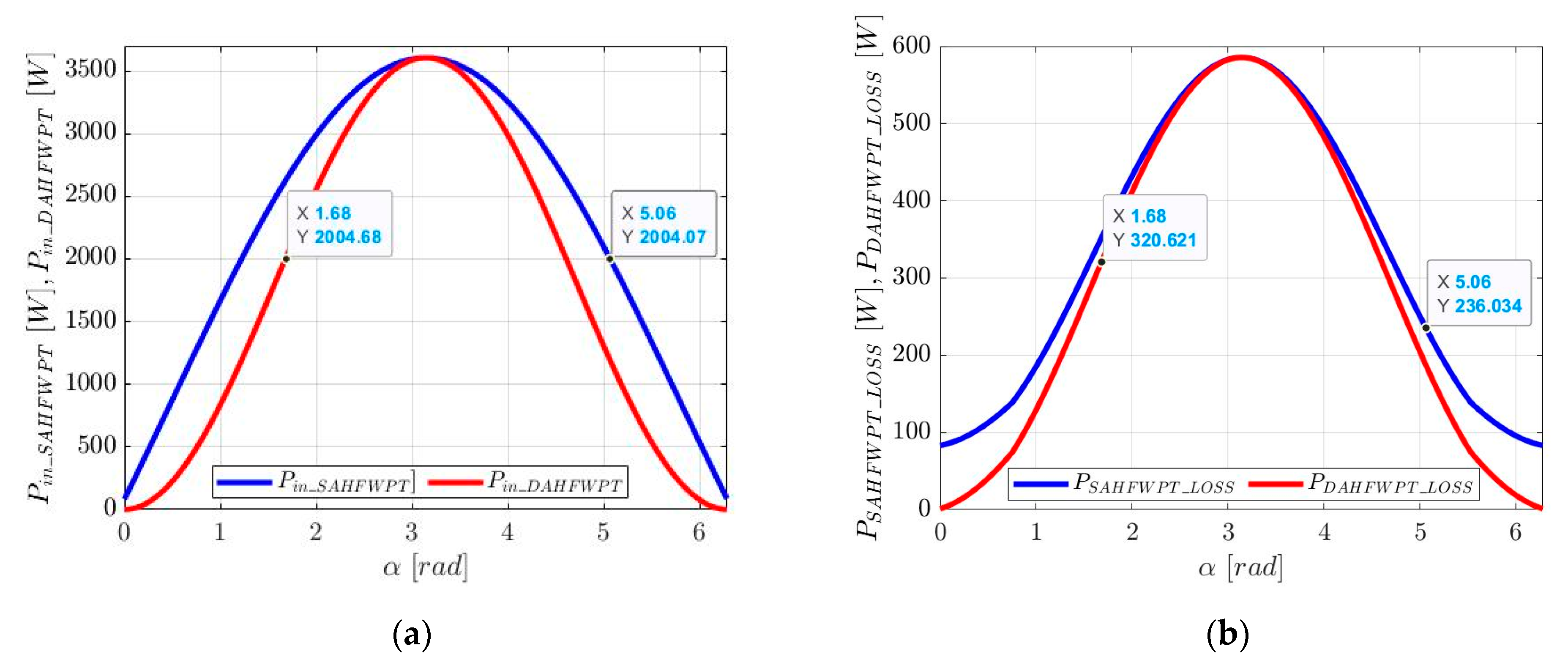
4. Efficiency of SAHFWPT and DAHFWPT

The efficiency is the ratio of the output power to the input power of any system. The general expression for efficiency is
η = P O P i n  
whereas P i n = P O + P l o s s with P l o s s denoting the overall losses of the system, P i n represents the input power and P O represents the output power. Equation (37) express the overall efficiency of the system. However, overall efficiency expression for SAHFWPT and DAHFWPT follow Equation (37). and are represented as η S A H F W P T and η D A H F W P T and formulated in Equations (38) and (39), respectively.
η S A H F W P T = P B P B + P S A H F W P T _ l o s s
η D A H F W P T = P B P B + P D A H F W P T _ l o s s
where P B represents the power at the battery end. P S A H F W P T _ l o s s and P D A H F W P T _ l o s s represent the overall loss of the SAHFWPT and DAHFWPT, respectively. They can be subdivided into the contributions provided by
P S A H F W P T _ l o s s = P S S _ c o i l _ S A H F W P T _ l o s s + P H F S R _ C o n d _ l o s s + P H F P C _ C o n d _ S _ l o s s + P C o s s _ l o s s + P b o d y _ l o s s + P H F P C _ o n _ _ o f f _ S _ l o s s
P D A H F W P T _ l o s s = P S S _ c o i l _ D A H F W P T _ l o s s + P H F S C _ C o n d _ l o s s + P H F P C _ C o n d _ D _ l o s s + P C o s s _ l o s s + P b o d y _ l o s s + P H F P C _ o n _ _ o f f _ D _ l o s s + P H F S C _ o n _ _ o f f _ l o s s
The Equations (40) and (41) represent the overall loss of the WPT system. That includes coil loss, conduction loss of switch, output capacitor of MOSFET discharging time loss, diode, body diode reverse recovery loss, and converter on and off losses are included for both the SAHFWPT and DAHFWPT system.

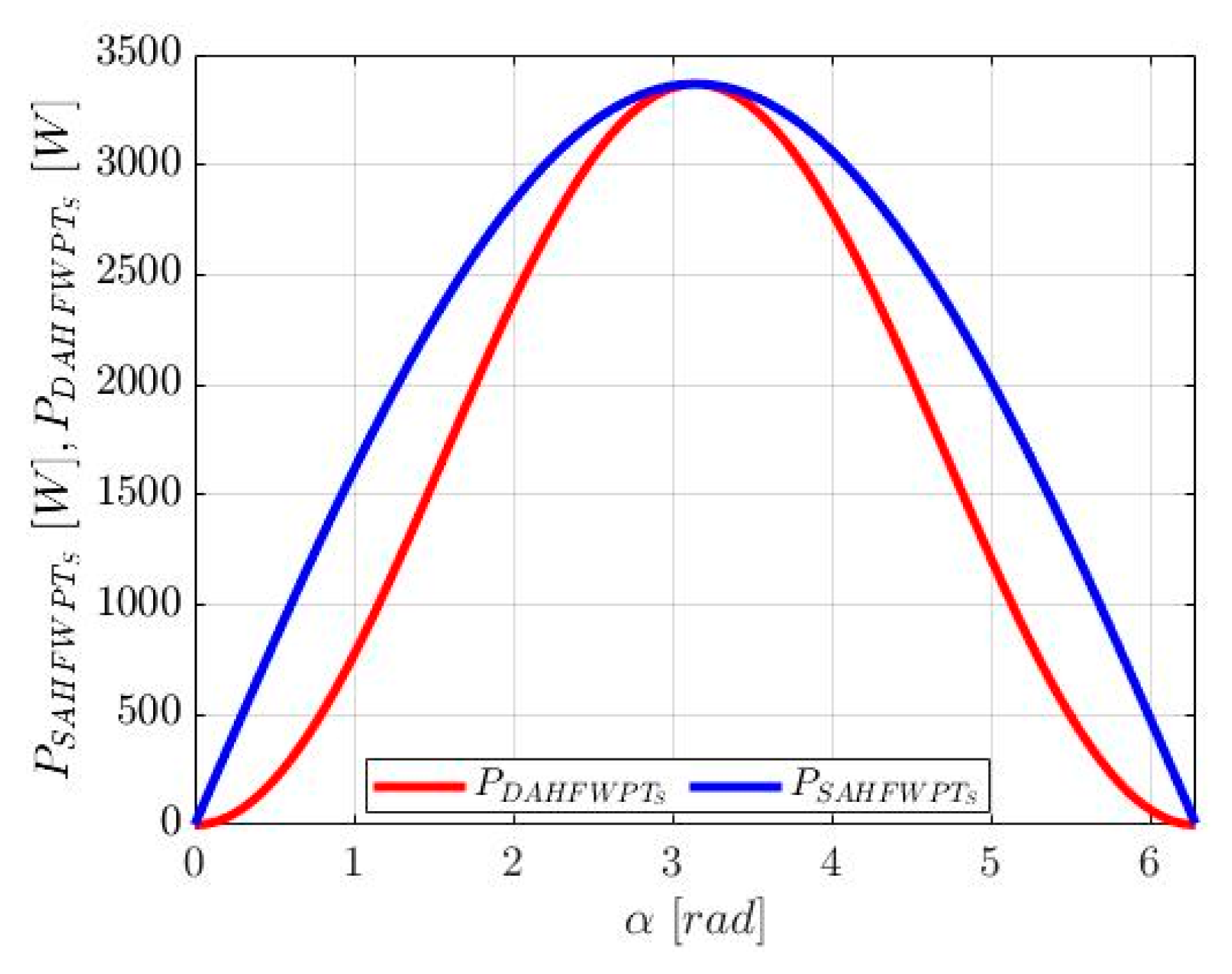
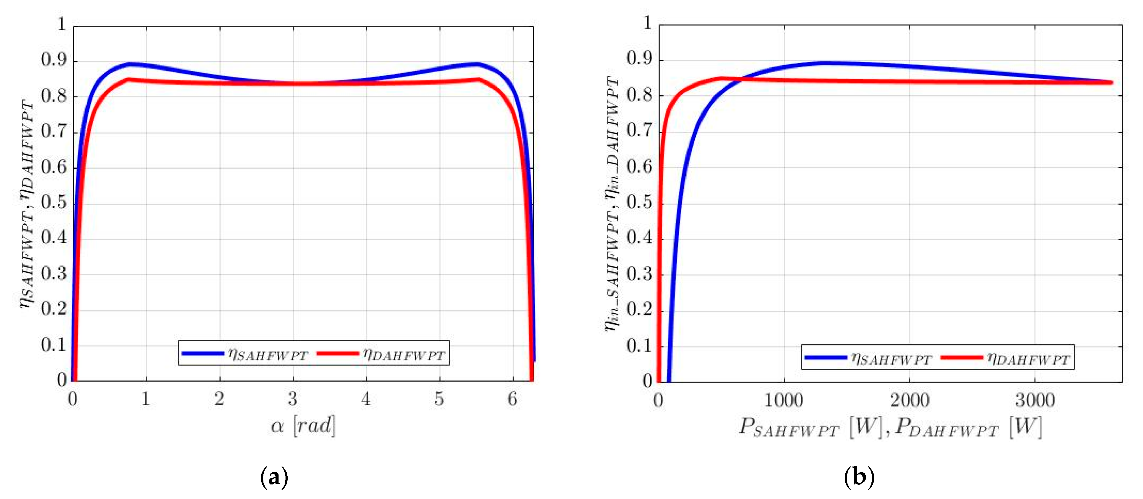
5. Simulation Results

The SAHFWPT and DAHFWPT in Figure 2a,b were simulated in MATLAB with the parameters specified in Table 4. This section presents the discussion about the overall losses and the efficiency of the system, described by the loss characteristics and efficiency curve. Voltage and current plots in Figure 7a refer to SAHFWPT, the solid blue line represent the output voltage of HFPC and the input voltage of HFSR in steady state and the corresponding currents using the solid red lines. Voltage and current plots in Figure 7b refer to DAHFWPS, the solid blue line the output voltage of HFPC and input voltage of HFSC in steady state, and the corresponding currents using the solid red lines. For a clear viewing of the current, the primary current and the secondary current are multiplied by the factors 20 and 3, respectively. Due to resonating behavior of the S-S coupling coil, the currents of primary and secondary coils are sinusoidal in nature and the voltage are a quasi-square wave. The input power ratings are 1252 W and 472 W at α = 0.73 for SAHFWPT and DAHFWPT, respectively.
The first column of Table 5 contains the different value of α . For the analysis, we consider α equal to β as a reference value. The second column reports the input power, the third column contains the overall loss of the system, the fourth column contains the overall loss in percentage. Columns two, three, and four are further subdivided into SAHFWPT and DAHFWPT. From the analytical data reported in Table 5, the percentage losses of SAHFWPT decrease as α decreases, but near to zero value of α , percentage losses increase. On the contrary, in the case of DAHFWPT, losses percentage is almost constant as α decreases but, as it happens with SAHFWPT, near to the zero value of α loss percentage increases and losses in DAHFWPT are higher than losses in SAHFWPT. However, the instantaneous input power of SAHFWPT and DAHFWPT at α = 0.33 are 604 W and 102 W. These results are obtained at Φ = 3π/2.
Figure 8a,b show the steady state input power and the loss curves of the SAHFWPT in solid blue line and DAHFWPT in solid red line. The input power of the system is in the range of 0 to 3600 W. As per Equation (18), SAHFWPT input power is always greater than DAHFWPT at equal α apart from α = π . Both input power and loss curve are symmetric with respect to α = 3.14 . From the loss curve, it is visible that the losses in SAHFWPT are always greater than losses in DAHFWPT. Consequently, for the same instantaneous input power in both systems, the losses are not same. For example, at the input power equal to 2004 W indicated by data tip at α = 1.68 and α = 5.06 , the losses are 320 W and 236 W for the DAHFWPT and the SAHFWPT, respectively. From the above discussion and Table 5 data, it is proven that the losses of SAHFWPT are less than or equal to the DAHFWPT.
Figure 9a presents efficiency plots, i.e., η S A H F W P T in solid blue line and η D A H F W P T in solid red line as a function of the internal phase shift angle α , obtained from (38) and (39) for the SAHFWPT and DAHFWPT, respectively. Both the maximum efficiencies of the SAHFWPT and DAHFWPT, i.e., 89.2% and 84.9%, are reached at α = 0.73 , respectively. The efficiencies η S A H F W P T and η D A H F W P T have two picks at α = 0.73   and   5.55 . For α in the ranges from 0.73 to 2.3 and from 3.98 to 5.55 the efficiency η S A H F W P T is always greater than η D A H F W P T . Moreover, in these range of η D A H F W P T the results nearly constant. For α ranging in the interval from 2.3 to 3.98, the efficiency η S A H F W P T is almost equal to η D A H F W P T .
Figure 9b reports the efficiency plots as a function of the input power P S A H F W P T and P D A H F W P T , obtained from (38) and (39), respectively. The maximum efficiencies of 89.2% and 84.9% of SAHFWPT and DAHFWPT are reached at P S A H F W P T = 1325   W and P D A H F W P T = 491   W , respectively. It is visible that the operating conditions of the SAHFWPT and DAHFWPT can be divided into two zones. When power P S A H F W P T is in the interval 648   W   3606   W , efficiency η S A H F W P T is greater than efficiency η D A H F W P T . However, for the input power P D A H F W P T less than 648 W, the efficiency η D A H F W P T is greater than the efficiency η S A H F W P T .
At the end of the study and their losses comparison of SAHFWPT and DAHFWPT, we are able to decide the superiority of the DC–DC converters, in terms of efficiency and input power. As per the above discussion, the efficiency performance of the SAHFWPT is greater than that of DAHFWPT in the medium power range. Indeed, at medium power the efficiency of the SAHFWPT is 4.3% more than the efficiency of the DAHFWPT. Whilst for the low power range the efficiency of the SAHFWPT is approximately 12% less than the efficiency of the DAHFWPT.

6. Conclusions

This article presents a step-by-step comparison study of the losses at different stages of converters and S-S coupling coils together with the control approaches of primary and secondary converters of the SAHFWPT and DAHFWPT, respectively, at a domestic load, i.e., domestic load input power up to 3600 W. This includes the uni-directional power flow estimation at each stage of the WPT system, such as the HFPC, primary coil, secondary coil, HFSC, and HFSR. The power assessment includes the estimation of system losses considering the switches losses, conduction losses, hard turn on and off losses, and S-S coil losses, etc. These estimations of the power are performed according to the SAE J2954 and the domestic grid power. To analyze the comparative performance of SAHFWPT and DAHFWPT, the two different converters control approaches, i.e., EPS and DPS methods took place by varying the internal and external phase shift angle. This was further verified through MATLAB, and the respective power loss and efficiency plots were drawn. Following from the simulation result discussion reported in Section 5 about the loss and efficiency of the SAHFWPT and the DAHFWPT, the efficiency of the SAHFWPT converter was found always superior at the medium power level of domestic use, i.e., 89.2%. Indeed, it has approximately 4% higher efficiency. Whereas in the lower and higher power ranges, the DAHFWPT is more efficient than the SAHFWPT with this method of control.
The literature has reported about the use of the SAHFWPT and DAHFWPT system to control the battery current during charging. Indeed, charging through the SAHFWPT needs one more DC–DC converter to control the battery charging. Nevertheless, since the efficiency of SAHFWPT is higher than that of DAHFWPT in medium power range of domestic use, we have a new result: if we are able to design the secondary DC–DC converter (i.e., chopper) having approximately 98% efficiency, then the SAHFWPT is superior in terms of efficiency at medium power of domestic use.

Author Contributions

Conceptualization, A.K. and M.B.; methodology A.K. and M.B.; software, A.K., M.B. and R.K.J.; validation, A.K.; formal analysis, A.K.; investigation, A.K.; resources A.K., M.B., R.K.J. and A.S.; data curation, A.K., M.B., R.K.J. and A.S.; writing-original draft preparation, A.K., M.B., R.K.J. and AS.; writing-review and editing, A.K., M.B., R.K.J. and A.S.; visualization, A.K., M.B., R.K.J. and A.S.; supervision, A.K. and M.B. All authors have read and agreed to the published version of the manuscript.

Funding

This research received no external funding.

Data Availability Statement

Most of the data and the results are reported in the paper. Additional data can be requested from the corresponding author.

Conflicts of Interest

The authors declare no conflict of interest.

Nomenclature

SAHFWPTSingle Active High-Frequency wireless power transfer
DAHFWPT Dual Active High-Frequency wireless power transfer
SPSSingle Phase Shift
EPSExtended Phase Shift
DPSDual Phase Shift
TPSTriple Phase shift
EVElectrical Vehicle
RERenewable Energy
ESSEnergy Storage System
SABSingle Active Bridge
DABDual Active Bridge
PSFBPhase Shift Full Bridge
DCDirect Current
V S Source Voltage
R B Battery Equivalent Resistance
C O Output low pass filter capacitor
L O Output low pass filter inductor
ZVS Zero Voltage Switching
ZCS Zero Current Switching
HFPCHigh-frequency Primary Converter
HFSCHigh-frequency Secondary Converter
HFSRHigh-frequency Secondary Rectifier
V D C P _ S ,   V D C P _ D DC voltage source of SAHFWPT and DAHFWPT
v H F P C _ S ,   v H F P C _ D Output voltage of HFPC of SAHFWPT and DAHFWPT
i P _ S ,   i P _ D Output current of HFPC of SAHFWPT and DAHFWPT
v H F S R _ S ,   v H F S C _ S Input voltage of HFSR and HFSC of SAHFWPT and DAHFWPT
i S _ S ,   i S _ D Input current of HFSR and HFSC of SAHFWPT and DAHFWPT
V O _ S , V O _ D Output voltage of HFSR and HFSC of SAHFWPT and DAHFWPT
ω r Resonant Frequency
ΦExternal Phase shift angle
αInternal phase shift angle of HFPC
βInternal phase shift angle of HFSC
v H F P C _ M ,   v H F S C _ M Peak amplitude of output and input voltage of HFPC and HFSC of DAHFWPT
v H F S R _ M Peak amplitude of input voltage of HFSR of SAHFWPT
CP, CSPrimary and secondary resonant capacitor
LP, LSPrimary and secondary coil self-inductance
RP, RSPrimary and secondary coil resistance
Z P , Z S Impedance of primary and secondary coil
MCoils mutual inductance
v P , v S Primary and secondary coil induce voltage
i P ,   i S Primary and secondary coil circulating current
P P S Average power flow from primary to secondary
v H F P C _ 1 ,   v H F S C _ 1 Fundamental Output and Input voltage of HFPC and HFSC of DAHFWPT
v H F S R _ 1 Fundamental of Input voltage of HFSR of SAHFWPT
i P _ D _ 1 ,   i P _ S _ 1 Fundamental primary coil current of DAHFWPT and SAHFWPT
i s _ 1 Fundamental secondary coil current of DAHFWPT and SAHFWPT
P D A H F W P T _ S ,   P S A H F W P T _ S Secondary Power of DAHFWPT and SAHFWPT
P S S _ c o i l _ D A H F W P T _ l o s s ,   P S S _ c o i l _ S A H F W P T _ l o s s   Coil Loss of DAHFWPT and SAHFWPT
η S S _ c o i l _ D A H F W P T ,   η S S _ c o i l _ S A H F W P T Efficiency of coil of DAHFWPT and SAHFWPT
P H F P C _ C o n d _ S _ l o s s ,   P H F S R _ C o n d _ l o s s Conduction loss of HFPC and HFSR of SAHFWPT
P H F P C _ C o n d _ D _ l o s s ,   P H F S C _ C o n d _ l o s s Conduction loss of HFPC and HFSC of DAHFWPT
P H F S C _ o n _ _ o f f _ l o s s Switching loss of switches for HFSC
P H F P C _ o n _ _ o f f _ D _ l o s s ,   P H F P C _ o n _ _ o f f _ S _ l o s s Switching loss of switches for HFPC of DAHFWPT and SAHFWPT
P C o s s _ l o s s Output capacitor loss of MOSFET
P b o d y _ l o s s Body diode reverse recovery loss
ηEfficiency
POOutput Power
P i n Input Power
P l o s s Power Loss
P B Power of Battery
P S A H F W P T _ l o s s Overall loss Power of SAHFWPT
P D A H F W P T _ l o s s Overall loss Power of DAHFWPT
η S A H F W P T Efficiency of SAHFWPT
η D A H F W P T Efficiency of DAHFWPT
WPTWireless Power Transfer

References

  1. Chen, T.; Zhang, X.-P.; Wang, J.; Li, J.; Wu, C.; Hu, M.; Bian, H. A Review on Electric Vehicle Charging Infrastructure Development in the UK. J. Mod. Power Syst. Clean Energy 2020, 8, 193–205. [Google Scholar] [CrossRef]
  2. Far, M.F.; Paakkinen, M.; Cremers, P. A Framework for Charging Standardisation of Electric Buses in Europe. In Proceedings of the IEEE Vehicle Power and Propulsion Conference (VPPC), Gijon, Spain, 18 November–16 December 2020; pp. 1–4. [Google Scholar]
  3. Bertoluzzo, M.; Giacomuzzi, S.; Kumar, A. Design of a Bidirectional Wireless Power Transfer System for Vehicle-to-Home Applications. Vehicles 2021, 3, 406–425. [Google Scholar] [CrossRef]
  4. Fontana, C.; Forato, M.; Bertoluzzo, M.; Buja, G. Design characteristics of SAB and DAB converters. In Proceedings of the Intl Aegean Conference on Electrical Machines & Power Electronics (ACEMP) Intl Conference on Optimization of Electrical & Electronic Equipment (OPTIM) & Intl Symposium on Advanced Electromechanical Motion Systems (ELECTROMOTION), Side, Turkey, 2–4 September 2015; pp. 661–668. [Google Scholar]
  5. Jha, R.; Forato, M.; Prakash, S.; Dashora, H.; Buja, G. An Analysis-Supported Design of a Single Active Bridge (SAB) Converter. Energies 2022, 15, 666. [Google Scholar] [CrossRef]
  6. Zhao, B.; Song, Q.; Liu, W.; Sun, Y. Overview of Dual-Active-Bridge Isolated Bidirectional DC–DC Converter for High-Frequency-Link Power-Conversion System. IEEE Trans. Power Electron. 2014, 29, 4091–4106. [Google Scholar] [CrossRef]
  7. Xu, F.; Wong, S.C.; Tse, C.K. Overall Loss Compensation and Optimization Control in Single-Stage Inductive Power Transfer Converter Delivering Constant Power. IEEE Trans. Power Electron. 2022, 37, 1146–1158. [Google Scholar] [CrossRef]
  8. Di Capua, G.; Femia, N.; Petrone, G.; Lisi, G.; Du, D.; Subramonian, R. Rajaram Subramonian. Power and efficiency analysis of high-frequency Wireless Power Transfer Systems. Int. J. Electr. Power Energy Syst. 2017, 84, 124–134. [Google Scholar] [CrossRef]
  9. J2954: Wireless Power Transfer for Light-Duty Plug-In/Electric Vehicles and Alignment Methodology; SAE International: Warrendale, PA, USA, 2020.
  10. Gonzalez-Gonzalez, J.M.; Trivino-Cabrera, A.; Aguado, J.A. Assessment of the Power Losses in a SAE J2954-Compliant Wireless Charger. IEEE Access 2022, 10, 54474–54483. [Google Scholar] [CrossRef]
  11. Ravikiran, V.; Keshri, R.; Rathore, A.; Chakraborty, C. Loss Analysis of Resonant Inductive Power Transfer System for Wireless Charging of e-Rickshaw. In Proceedings of the IEEE 28th International Symposium on Industrial Electronics (ISIE), Vancouver, BC, Canada, 12–14 June 2019; pp. 2559–2564. [Google Scholar]
  12. Di Capua, G.; Femia, N.; Lisi, G. Impact of losses and mismatches on power and efficiency of Wireless Power Transfer Systems with controlled secondary-side rectifier. Integration 2016, 55, 384–392. [Google Scholar] [CrossRef]
  13. Acquaviva, A.; Rodionov, A.; Kersten, A.; Thiringer, T.; Liu, Y. Analytical Conduction Loss Calculation of a MOSFET Three-Phase Inverter Accounting for the Reverse Conduction and the Blanking Time. IEEE Trans. Ind. Electron. 2021, 68, 6682–6691. [Google Scholar] [CrossRef]
  14. Kalra, G.R.; Pearce, M.G.S.; Kim, S.; Thrimawithana, D.J.; Covic, G.A. A Power Loss Measurement Technique for Inductive Power Transfer Magnetic Couplers. IEEE J. Emerg. Sel. Topics Ind. Electron. 2020, 1, 113–122. [Google Scholar] [CrossRef]
  15. Carretero, C. Coupling Power Losses in Inductive Power Transfer Systems with Litz-Wire Coils. IEEE Trans. Ind. Electron. 2017, 64, 4474–4482. [Google Scholar] [CrossRef]
  16. Rossmanith, H.; Doebroenti, M.; Albach, M.; Exner, D. Measurement and Characterization of High Frequency Losses in Nonideal Litz Wires. IEEE Trans. Power Electron. 2011, 26, 3386–3394. [Google Scholar] [CrossRef]
  17. Ren, Y.; Xu, M.; Zhou, J.; Lee, F. Analytical loss model of power MOSFET. IEEE Trans. Power Electron. 2006, 21, 310–319. [Google Scholar]
  18. Huang, Z.; Lam, C.S.; Mak, P.I.; Martins, R.S.; Wong, S.C.; Tse, C.K. A Single-Stage Inductive-Power-Transfer Converter for Constant-Power and Maximum-Efficiency Battery Charging. IEEE Trans. on Power Electron. 2020, 35, 8973–8984. [Google Scholar] [CrossRef]
  19. Fu, M.; Tang, Z.; Liu, M.; Ma, C.; Zhu, X. Full-bridge rectifier input reactance compensation in Megahertz wireless power transfer systems. In Proceedings of the IEEE PELS Workshop on Emerging Technologies: Wireless Power, Daejeon, Republic of Korea, 5–6 June 2015; pp. 1–5. [Google Scholar]
  20. Enssle, A.; Parspour, N. Power Loss Shifted Design of Inductive Energy Transfer Systems. IEEE Open J. Power Electron. 2020, 1, 113–123. [Google Scholar] [CrossRef]
  21. Shiba, K.; Morimasa, A.; Hirano, H. Design and Development of Low-Loss Transformer for Powering Small Implantable Medical Devices. IEEE Trans. Biomed. Circuits Syst. 2010, 4, 77–85. [Google Scholar] [CrossRef] [PubMed]
  22. Di Capua, G.; Sánchez, J.A.; Cabrera, A.T.; Cabrera, D.F.; Femia, N.; Petrone, G.; Spagnuolo, G. A losses-based analysis for electric vehicle wireless chargers. In Proceedings of the International Conference on Synthesis, Modeling, Analysis and Simulation Methods and Applications to Circuit Design (SMACD), Istanbul, Turkey, 7–9 September 2015; pp. 1–4. [Google Scholar]
  23. Sagar, A.; Kumar, A.; Bertoluzzo, M.; Jha, R.K. Analysis and Design of a Two-winding Wireless Power Transfer System with Higher System Efficiency and Maximum Load Power. In Proceedings of the IECON 2022—48th Annual Conference of the IEEE Industrial Electronics Society, Brussels, Belgium, 17–20 October 2022; pp. 1–6. [Google Scholar]
  24. Van Mulders, J.; Delabie, D.; Lecluyse, C.; Buyle, C.; Callebaut, G.; Van der Perre, L.; De Strycker, L. Wireless Power Transfer: Systems, Circuits, Standards, and Use Cases. Sensors 2022, 22, 5573. [Google Scholar] [CrossRef] [PubMed]
  25. Turzyński, M.; Bachman, S.; Jasiński, M.; Piasecki, S.; Ryłko, M.; Chiu, H.-J.; Kuo, S.-H.; Chang, Y.-C. Analytical Estimation of Power Losses in a Dual Active Bridge Converter Controlled with a Single-Phase Shift Switching Scheme. Energies 2022, 15, 8262. [Google Scholar] [CrossRef]
  26. Oggier, G.G.; García, G.O.; Oliva, A.R. Switching Control Strategy to Minimize Dual Active Bridge Converter Losses. IEEE Trans. Power Electron. 2009, 24, 1826–1838. [Google Scholar] [CrossRef]
  27. Bai, H.; Mi, C. Eliminate Reactive Power and Increase System Efficiency of Isolated Bidirectional Dual-Active-Bridge DC–DC Converters Using Novel Dual-Phase-Shift Control. IEEE Trans. Power Electron. 2008, 23, 2905–2914. [Google Scholar] [CrossRef]
Figure 1. Schematic of wireless DC–DC converter.
Energies 16 01795 g001
Figure 2. Schematic of WPT converter with equivalent load (a) SAHFWPT (b) DAHFWPT.
Energies 16 01795 g002
Figure 3. Control signal and operating waveform of WPT (a) SAHFWPT (b) DAHFWPT.
Energies 16 01795 g003
Figure 4. Equivalent circuit of the SAHFWPT and DAHFWPT with S-S coupling.
Energies 16 01795 g004
Figure 5. Secondary of the S-S coupling coil power relation of SAHFWPT and DAHFWPT w.r.t. α .
Energies 16 01795 g005
Figure 6. S-S coupling coil efficiency of SAHFWPT and DAHFWPT w.r.t. α .
Energies 16 01795 g006
Figure 7. Current (red) and voltage (blue) wave input of primary coil and output of the secondary coil of (a) SAHFWPT (b) and DAHFWPT.
Energies 16 01795 g007
Figure 8. (a) Input power (b) overall losses of the system w.r.t. α .
Energies 16 01795 g008
Figure 9. Efficiency of WPT system (a) w.r.t. α (b) w.r.t. P S A H F W P T   a n d   P D A H F W P T .
Energies 16 01795 g009
Table 1. A comparison is made between a SAHFWPT and a DAHFWPT.
FeatureSAHFWPTDAHFWPT
Reference[3][5][6,7,8,9][3][5][6,7,8,9]
Switching controlSPS××
EPS×
DPS×××
TPS××××
Additional chopper×××
Hard switching of MOSFET××××
Circulating current××××
S-S coil loss
Overall loss analysis××××
Table 2. DAHFWPT current voltage expressions at fundamental harmonic.
v H F P C _ 1 t = v H F P C _ 1 _ M sin α 2 sin ω r t (8) v H F S C _ 1 t = v H F S C _ 1 _ M sin β 2 sin ω r t + Φ (9)
i P _ D _ 1 t = v H F S C _ 1 _ M M ω r sin β 2 cos ω r t + Φ (10) i s _ 1 t = v H F P C _ 1 _ M M ω r sin α 2 cos ω r t (11)
Table 3. SAHFWPT current voltage expressions at fundamental harmonic.
v H F P C _ 1 t = v H F P C _ 1 _ M sin α 2 sin ω r t (12) v H F S R _ 1 t = v H F S R _ 1 _ M sin ω r t + Φ (13)
i P _ S _ 1 t = v H F S R _ 1 _ M M ω r cos ω r t + Φ (14) i s _ 1 t = v H F P C _ 1 _ M M ω r sin α 2 cos ω r t (15)
Table 4. Simulation parameter for EV.
ParametersSymbolsValues
Source Rated Voltage V D C P _ S ,   V D C P _ D 384 V
Battery Rated voltage V O _ S , V O _ D 120 V
Resonating frequency f r 85 kHz
MOSFETs T 5 T 12 SiHG33N60EF
Self-Inductance L P L S 220 µH
Compensation Capacitors C P C S 15.9 nF
S-S coil Resistance R P R S 0.5 Ω
Mutual-InductanceM22.5 µH
Table 5. Overall loss analytical data for SAHFWPT and DAHFWPT at Φ = 3π/2 and α = β.
αInput PowerLoss into the System% Loss into the System
SAHFWPTDAHFWPTSAHFWPTDAHFWPTSAHFWPTDAHFWPT
3.123605360558658616.2516.25
2.163146280746945314.9716.15
1.822795225238836113.8716.05
1.442312157429025012.5415.88
1.141881105721716511.5115.65
0.7312454671367110.9415.23
0.33605102992316.3422.43
Disclaimer/Publisher’s Note: The statements, opinions and data contained in all publications are solely those of the individual author(s) and contributor(s) and not of MDPI and/or the editor(s). MDPI and/or the editor(s) disclaim responsibility for any injury to people or property resulting from any ideas, methods, instructions or products referred to in the content.

